

Page 1

GP50 GRADIENT PUMP
OPERATOR'S MANUAL
© 2001 Dionex Corporation
Document No. 031377
Revision 03
July 2001
Page 2

©2001 by Dionex Corporation
All rights reserved worldwide.
Printed in the United States of Amer ica.
This publication is protected by federal copyright law. No part of this publication
may be copied or distributed, transm itted, tr anscri bed , stored in a retrieval system, or
transmitted into any human or computer language, in any form or by any means,
electronic, mechanical, magnetic, manual, or otherwise, or disclosed to third parties
without the express written permission of Dionex Corporation, 1228 Titan Way,
Sunnyvale, California 94088-3603 U.S.A.
DISCLAIMER OF WARRANTY AND LIMITED WARRANTY
THIS PUBLICATION IS PROVIDED “AS IS” WITHOUT WARRANT Y OF
ANY KIND. DIONEX CORPORATION DOES NOT WARRANT,
GUARANTEE, OR MAKE ANY EXPRESS OR IMPLIED
REPRESENTATI ONS RE GARD ING THE U SE, O R TH E RES ULTS OF THE
USE, OF THIS PUBLICATION IN TERMS OF CORRECTNESS, ACCURACY,
RELIABILITY, CURRENTNESS, OR OTHERWISE. FURTHER, DIONEX
CORPORATION RESERVES THE RIGHT TO REVISE THIS PUBLICATION
AND TO MAKE CHANGES FROM TIME TO TIME IN THE CONTENT
HEREINOF WITHOUT OBLIGATION OF DIONEX CORPORATION TO
NOTIFY ANY PERSON OR ORGANIZATION OF SUCH REVI SION OR
CHANGES.
TRADEMARKS
DX-LAN™ is a trademark, and PeakNet®, Self-Regenerating Suppressor®, and
SRS® are registered trademarks of Dionex Corporation
Tefzel® is a registered trademark of E.I. duPont de Nemours & Co.
PRINTING HISTORY
Revision 01, May 1998
Revision 02, October 2000
Revision 03, July 2001
Page 3

Contents
1 • Introduction
1.1 Overview . . . . . . . . . . . . . . . . . . . . . . . . . . . . . . . . . . . . . . . . . . . . . . . .1-1
1.2 About This Manual . . . . . . . . . . . . . . . . . . . . . . . . . . . . . . . . . . . . . . . .1-2
1.2.1 Safety Messages and Notes . . . . . . . . . . . . . . . . . . . . . . . . . . .1-3
1.2.2 Safety Labels . . . . . . . . . . . . . . . . . . . . . . . . . . . . . . . . . . . . . .1-4
2 • Description
2.1 Front Control Panel . . . . . . . . . . . . . . . . . . . . . . . . . . . . . . . . . . . . . . . .2-2
2.1.1 Control Panel Keypad . . . . . . . . . . . . . . . . . . . . . . . . . . . . . . .2-3
2.1.2 Display Screens . . . . . . . . . . . . . . . . . . . . . . . . . . . . . . . . . . . .2-7
2.2 Electronics Chassis . . . . . . . . . . . . . . . . . . . . . . . . . . . . . . . . . . . . . . . .2-8
2.3 Mechanical Chassis . . . . . . . . . . . . . . . . . . . . . . . . . . . . . . . . . . . . . . .2-11
2.4 Mechanical Components . . . . . . . . . . . . . . . . . . . . . . . . . . . . . . . . . . .2-12
2.5 Vacuum Degas Pump Assembly (Optional) . . . . . . . . . . . . . . . . . . . .2-16
2.6 Piston Seal Wash (Optional) . . . . . . . . . . . . . . . . . . . . . . . . . . . . . . . .2-16
2.7 Eluent Reservoirs . . . . . . . . . . . . . . . . . . . . . . . . . . . . . . . . . . . . . . . . .2-17
Doc. 031377-03 7/01
2.4.1 Pump Eluent Manifold . . . . . . . . . . . . . . . . . . . . . . . . . . . . . .2-13
2.4.2 Pump Heads . . . . . . . . . . . . . . . . . . . . . . . . . . . . . . . . . . . . . .2-14
2.4.3 Pump Mixers . . . . . . . . . . . . . . . . . . . . . . . . . . . . . . . . . . . . .2-14
2.4.4 Pump Priming Block . . . . . . . . . . . . . . . . . . . . . . . . . . . . . . .2-15
2.4.5 Pressure Transducer . . . . . . . . . . . . . . . . . . . . . . . . . . . . . . . .2-15
i
Page 4

GP50 Gradient Pump
2.8 Rear Panel . . . . . . . . . . . . . . . . . . . . . . . . . . . . . . . . . . . . . . . . . . . . . . 2-18
2.9 Functional Description . . . . . . . . . . . . . . . . . . . . . . . . . . . . . . . . . . . . 2-18
2.9.1 Operating and Control Modes . . . . . . . . . . . . . . . . . . . . . . . . 2-18
2.9.2 Local and Remote Modes . . . . . . . . . . . . . . . . . . . . . . . . . . . 2-19
2.9.3 Method Control . . . . . . . . . . . . . . . . . . . . . . . . . . . . . . . . . . . 2-20
2.9.4 Eluent Delivery . . . . . . . . . . . . . . . . . . . . . . . . . . . . . . . . . . . 2-22
3 • Operation and Maintenance
3.1 Getting Ready to Run . . . . . . . . . . . . . . . . . . . . . . . . . . . . . . . . . . . . . . 3-1
3.1.1 Degas Eluents . . . . . . . . . . . . . . . . . . . . . . . . . . . . . . . . . . . . . 3-1
3.1.2 Filter Eluents . . . . . . . . . . . . . . . . . . . . . . . . . . . . . . . . . . . . . . 3-2
3.1.3 Pressurize Eluent Reservoirs . . . . . . . . . . . . . . . . . . . . . . . . . . 3-2
3.1.4 Start-Up . . . . . . . . . . . . . . . . . . . . . . . . . . . . . . . . . . . . . . . . . . 3-3
3.1.5 Selecting the Pressure Limits . . . . . . . . . . . . . . . . . . . . . . . . . 3-4
3.1.6 Selecting the Operating and Control Modes . . . . . . . . . . . . . . 3-5
3.2 Running Under Direct Control (Local Mode) . . . . . . . . . . . . . . . . . . . 3-6
3.3 Running Under Method Control (Local Mode) . . . . . . . . . . . . . . . . . . 3-7
3.3.1 Creating a New Method . . . . . . . . . . . . . . . . . . . . . . . . . . . . . . 3-8
3.3.2 Running a Method . . . . . . . . . . . . . . . . . . . . . . . . . . . . . . . . .3-10
3.3.3 Editing a Method . . . . . . . . . . . . . . . . . . . . . . . . . . . . . . . . . . 3-11
3.3.4 Deleting a Method . . . . . . . . . . . . . . . . . . . . . . . . . . . . . . . . . 3-12
3.3.5 Changing the Running Method . . . . . . . . . . . . . . . . . . . . . . . 3 -12
3.3.6 Controlling the Method Clock . . . . . . . . . . . . . . . . . . . . . . . .3-12
ii
Doc. 031377 -03 7/01
Page 5

3.4 Example Methods . . . . . . . . . . . . . . . . . . . . . . . . . . . . . . . . . . . . . . . .3-13
3.4.1 Isocratic Method Example . . . . . . . . . . . . . . . . . . . . . . . . . . .3-13
3.4.2 Linear Gradient Method Example . . . . . . . . . . . . . . . . . . . . .3-14
3.4.3 Curved Gradient Method Example . . . . . . . . . . . . . . . . . . . . .3-19
3.4.4 Editing a Running Method Example . . . . . . . . . . . . . . . . . . .3-23
3.5 Routine Maintenance . . . . . . . . . . . . . . . . . . . . . . . . . . . . . . . . . . . . . .3-25
3.5.1 Daily Maintenance . . . . . . . . . . . . . . . . . . . . . . . . . . . . . . . . .3-25
3.5.2 Periodic Maintenance . . . . . . . . . . . . . . . . . . . . . . . . . . . . . . .3-27
3.6 Shutdown . . . . . . . . . . . . . . . . . . . . . . . . . . . . . . . . . . . . . . . . . . . . . . .3-27
4 • Troubleshooting
4.1 Left-Right Pump Head Pressure Fluctuations . . . . . . . . . . . . . . . . . . . .4-1
Contents
4.2 Pump Will Not Start . . . . . . . . . . . . . . . . . . . . . . . . . . . . . . . . . . . . . . .4-3
4.3 Pump Stops . . . . . . . . . . . . . . . . . . . . . . . . . . . . . . . . . . . . . . . . . . . . . .4-3
4.4 Liquid Leaks/Leak Alarm . . . . . . . . . . . . . . . . . . . . . . . . . . . . . . . . . . .4-7
4.5 Noisy Pump Motor . . . . . . . . . . . . . . . . . . . . . . . . . . . . . . . . . . . . . . . .4-8
4.6 Vacuum Degas Pump Does Not Run . . . . . . . . . . . . . . . . . . . . . . . . . .4-9
4.7 Vacuum Degas Pump Calibration Fails . . . . . . . . . . . . . . . . . . . . . . .4-10
4.8 Vacuum Degas Pump Low Vacuum . . . . . . . . . . . . . . . . . . . . . . . . . .4-11
4.9 Relays or TTLs Inoperative . . . . . . . . . . . . . . . . . . . . . . . . . . . . . . . . .4-11
4.10 Poor Chromatographic Reproducibility . . . . . . . . . . . . . . . . . . . . . . .4-12
Doc. 031377-03 7/01
iii
Page 6

GP50 Gradient Pump
5•Service
5.1 Cleaning and Replacing the Check Valves . . . . . . . . . . . . . . . . . . . . . . 5-1
5.2 Piston Seal Replacement . . . . . . . . . . . . . . . . . . . . . . . . . . . . . . . . . . . 5-4
5.3 Pump Piston Replacement . . . . . . . . . . . . . . . . . . . . . . . . . . . . . . . . . . 5-8
5.4 Pressure Transducer Waste Valve O-Ring Replacement . . . . . . . . . . 5-10
5.5 Proportioning Valve Replacement . . . . . . . . . . . . . . . . . . . . . . . . . . .5-11
5.6 Changing Main Power Fuses . . . . . . . . . . . . . . . . . . . . . . . . . . . . . . . 5-13
A • Specifications
A.1 Electrical . . . . . . . . . . . . . . . . . . . . . . . . . . . . . . . . . . . . . . . . . . . . . . . .A-1
A.2 Environmental . . . . . . . . . . . . . . . . . . . . . . . . . . . . . . . . . . . . . . . . . . .A-1
A.3 Physical . . . . . . . . . . . . . . . . . . . . . . . . . . . . . . . . . . . . . . . . . . . . . . . . .A-1
A.4 Display and Keypad . . . . . . . . . . . . . . . . . . . . . . . . . . . . . . . . . . . . . . .A-1
A.5 Hydraulics . . . . . . . . . . . . . . . . . . . . . . . . . . . . . . . . . . . . . . . . . . . . . . .A-2
A.6 Control . . . . . . . . . . . . . . . . . . . . . . . . . . . . . . . . . . . . . . . . . . . . . . . . .A-3
A.7 Vacuum Degas Pump Assembly (Optional) . . . . . . . . . . . . . . . . . . . . .A-3
B • Installation
B.1 Facility Requirements . . . . . . . . . . . . . . . . . . . . . . . . . . . . . . . . . . . . . .B-1
B.2 Installation Instructions . . . . . . . . . . . . . . . . . . . . . . . . . . . . . . . . . . . .B-2
B.2.1 Power Connection . . . . . . . . . . . . . . . . . . . . . . . . . . . . . . . . . .B-2
B.2.2 Electronics Chassis Connections . . . . . . . . . . . . . . . . . . . . . . .B-4
B.2.3 DX-L AN Interface: 10B ASE-T Connections (Optional). . . . .B-6
iv
Doc. 031377 -03 7/01
Page 7

B.2.4 DX-LAN Interface: BNC Connections (Optional) . . . . . . . . . B-9
B.2.5 Waste Lines. . . . . . . . . . . . . . . . . . . . . . . . . . . . . . . . . . . . . . B-13
B.2.6 Eluent Inlet Line Connections. . . . . . . . . . . . . . . . . . . . . . . . B-14
B.2.7 Eluent Outlet Line Connections . . . . . . . . . . . . . . . . . . . . . . B-14
B.2.8 Piston Seal Wash Connections (Optional) . . . . . . . . . . . . . . B-15
B.2.9 Priming the Pump . . . . . . . . . . . . . . . . . . . . . . . . . . . . . . . . . B-17
B.3 Automatic SRS Power Control (Optional) . . . . . . . . . . . . . . . . . . . . B-20
C • Display Screens
C.1 Operational Screens . . . . . . . . . . . . . . . . . . . . . . . . . . . . . . . . . . . . . . . C-2
C.1.1 Menu of Screens . . . . . . . . . . . . . . . . . . . . . . . . . . . . . . . . . . . C-2
C.1.2 Main Screen. . . . . . . . . . . . . . . . . . . . . . . . . . . . . . . . . . . . . . . C-3
Contents
C.2 Diagnostic Screens . . . . . . . . . . . . . . . . . . . . . . . . . . . . . . . . . . . . . . C-14
Doc. 031377-03 7/01
C.1.3 Detail Screen. . . . . . . . . . . . . . . . . . . . . . . . . . . . . . . . . . . . . . C-5
C.1.4 Method Screen. . . . . . . . . . . . . . . . . . . . . . . . . . . . . . . . . . . . . C-6
C.1.5 Method Extension Screen . . . . . . . . . . . . . . . . . . . . . . . . . . . . C-8
C.1.6 Degas Options. . . . . . . . . . . . . . . . . . . . . . . . . . . . . . . . . . . . . C-9
C.1.7 Module Setup . . . . . . . . . . . . . . . . . . . . . . . . . . . . . . . . . . . . C-11
C.1.8 Pump Options . . . . . . . . . . . . . . . . . . . . . . . . . . . . . . . . . . . . C-12
C.1.9 Time Function In. . . . . . . . . . . . . . . . . . . . . . . . . . . . . . . . . . C-13
C.2.1 Diagnostic Menu. . . . . . . . . . . . . . . . . . . . . . . . . . . . . . . . . . C-14
C.2.2 Power-Up Screen. . . . . . . . . . . . . . . . . . . . . . . . . . . . . . . . . . C-15
C.2.3 Elapsed Time. . . . . . . . . . . . . . . . . . . . . . . . . . . . . . . . . . . . . C-16
C.2.4 DSP Status. . . . . . . . . . . . . . . . . . . . . . . . . . . . . . . . . . . . . . . C-17
v
Page 8

GP50 Gradient Pump
C.2.5 DX-LAN Status . . . . . . . . . . . . . . . . . . . . . . . . . . . . . . . . . . .C-18
C.2.6 Keyboard Test . . . . . . . . . . . . . . . . . . . . . . . . . . . . . . . . . . . .C-20
C.2.7 Diagnostic Test. . . . . . . . . . . . . . . . . . . . . . . . . . . . . . . . . . . .C-21
C.2.8 Pressure Statistics. . . . . . . . . . . . . . . . . . . . . . . . . . . . . . . . . .C-23
C.2.9 DSP Code Version . . . . . . . . . . . . . . . . . . . . . . . . . . . . . . . . .C-24
C.3 Calibration Screens . . . . . . . . . . . . . . . . . . . . . . . . . . . . . . . . . . . . . . .C-25
C.3.1 Calibration Menu . . . . . . . . . . . . . . . . . . . . . . . . . . . . . . . . . .C-25
C.3.2 Calibration Status. . . . . . . . . . . . . . . . . . . . . . . . . . . . . . . . . .C-26
C.3.3 Leak Sensor Calibration and Status . . . . . . . . . . . . . . . . . . . .C-27
C.3.4 Degas Status. . . . . . . . . . . . . . . . . . . . . . . . . . . . . . . . . . . . . .C-28
C.3.5 Flow Calibration. . . . . . . . . . . . . . . . . . . . . . . . . . . . . . . . . . .C-29
C.3.6 Pressure Calibration . . . . . . . . . . . . . . . . . . . . . . . . . . . . . . . .C-30
C.3.7 Degas Pump Calibration. . . . . . . . . . . . . . . . . . . . . . . . . . . . .C-34
D • TTL and Relay Control
D.1 TTL and Relay Output Operation . . . . . . . . . . . . . . . . . . . . . . . . . . . . .D-2
D.2 TTL Input Operation . . . . . . . . . . . . . . . . . . . . . . . . . . . . . . . . . . . . . .D-3
D.2.1 TTL Input Signal Modes . . . . . . . . . . . . . . . . . . . . . . . . . . . . .D-3
D.3 TTL and Relay Connections . . . . . . . . . . . . . . . . . . . . . . . . . . . . . . . . .D-5
D.3.1 Example Connections. . . . . . . . . . . . . . . . . . . . . . . . . . . . . . . .D-6
vi
Doc. 031377 -03 7/01
Page 9

1.1 Overview
The GP50 Gradient Pump is an integral part of a Dione x chr omat ogr aphy system.
It is a microprocess or -based, dua l-pisto n, v ariable -speed, gr adient de li ver y system
designed to blend and pump mixtures of up to four different eluents at precisely
controlled flow rates. The pump can deliver the selected eluent composition
isocratically, or as a multistep linear or curved gradient. A Digital Signal
Processor (DSP) provides high speed control of pump flow and pressure.
The pump can operate as a stand-alone product or with other Dionex modules as
part of a complete chromatography system. It can also be used with non-Dionex
modules that meet interface requirements for software, TTL, or relay control.
The GP50 can be controlled locally, using the front panel keypad and display, or
from a remote host computer with a Dionex DX-LAN™ interface installed and
®
PeakNet
ava ilabl e from an y de vi ce capabl e of pro v iding compati ble TTL signa ls to contr ol
the pump.
The pump's two basic mode s of control, Dire ct control and Method control, e nable
it to operat e with or without reference to time-based events.
software installed on t he hos t comput er. Limited remote control is also
1 • Introduction
The GP50 is available in four versions. An optional vacuum degas pump is
available for all versions:
GP50 Gradient Pump V e r sio n With Degas Pump Without Degas Pump
Standard bore with PEEK
components
Standard bore with stainless steel
components
Microbore with PEEK components P/N 054045 P/N 054429
Microbore with stainless steel
components
Doc. 031377-03 7/01
P/N 054426 P/N 054427
P/N 054419 P/N 054420
P/N 054425 P/N 054424
1-1
Page 10

GP50 Gradient Pump
1.2 About This Manual
Chapter 1
Introduction
Chapter 2
Description
Chapter 3
Operation and
Maintenance
Chapter 4
Troubleshooting
Chapter 5
Service
Appendix A
Specifications
Appendix B
Installation
Appendix C
Display Screens
Appendix D
TTL and Relay
Control
Gives an overview of the GP50 Gradient Pump, and
explains conventions used in this manual, including
safety-related information.
Describes the GP50 front panel controls, electronic and
mechanical components, and operating modes.
Provides an overview of GP50 opera tion, including how to
create, edit, and run methods from the GP50 front panel.
Lists routine preventive maintenance procedures.
Lists problems and presents step-by-step procedures for
how to isolate and eliminat e them.
Provides step-by-step instructions for routine service and
parts replacement procedures.
Lists the GP50 specifications and installation site
requirements.
Describes how to install the GP50.
Illustrates and describes all of the screens that can be
displayed on the GP50 front panel.
Describes relay and TTL input and output functions and
provides installation instructions
.
1-2
Doc. 031377 -03 7/01
Page 11
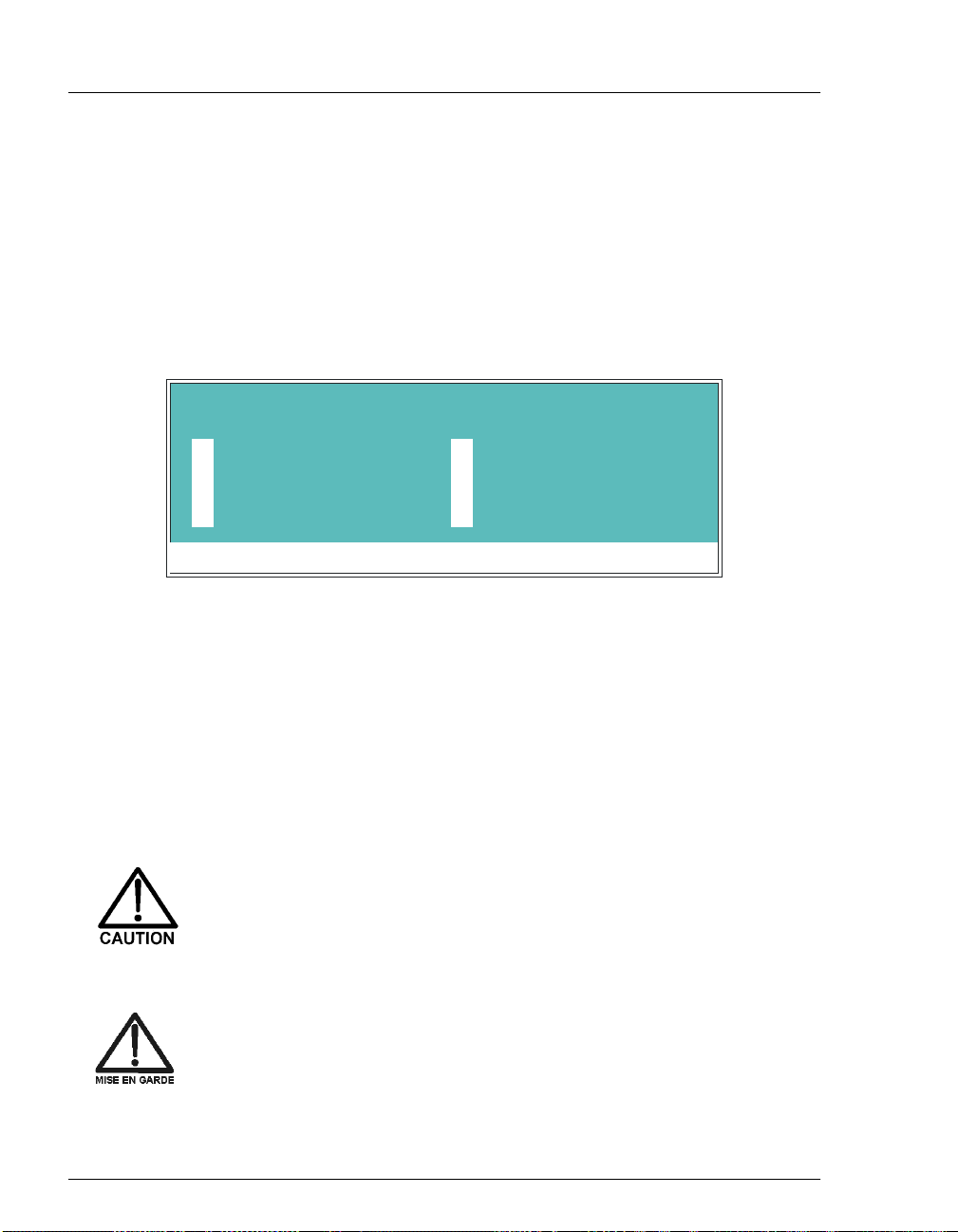
1.2.1 Saf et y Me ss a ges and Note s
This manual contains warnings and precautionary statements that, when
properly followed, can prevent personal injury and/or damage to the
GP50. Safety messages appear in bold type and are accompanied by
icons, as shown below.
Indicates an imminently hazardous situation which, if not
avoided, will result in death or serious injury.
Indicates a potentially hazardous situation which, if not
avoided, could result in death or serious injury.
Indicates a potentially hazardous situation which, if not
avoided, may result in minor or moderate injury.
1 • Introduction
Doc. 031377-03 7/01
Indicates that the function or process of the instrument may be
impaired. Operation does not constitute a hazard.
Informational messages also appear throughout this manual. These are
labeled NOTE and are in bold type:
NOTE NOTES call attention to certain information. They alert
you to an unexpected result of an action, suggest how to
optimize instrument performance, etc.
1-3
Page 12

GP50 Gradient Pump
1.2.2 Saf et y Label s
The TUV GS, C, US Mark safety label and the CE Mark label on the
GP50 indicate that the GP50 is in compliance with the following
standards: EN 61010-1:1993 (safety), CAN/CSA-C22.2 No. 1010.1-92
(safety), UL 3101-1/10.93 (safety), EN 50082-1:1992 (susceptibility),
and EN 55011:1991 (emissions).
The symbols below appear on the GP50, or on GP50 labels.
Alternating current
Protective conductor terminal
Power supply is on
Power supply is off
1-4
Doc. 031377 -03 7/01
Page 13
2 • Description
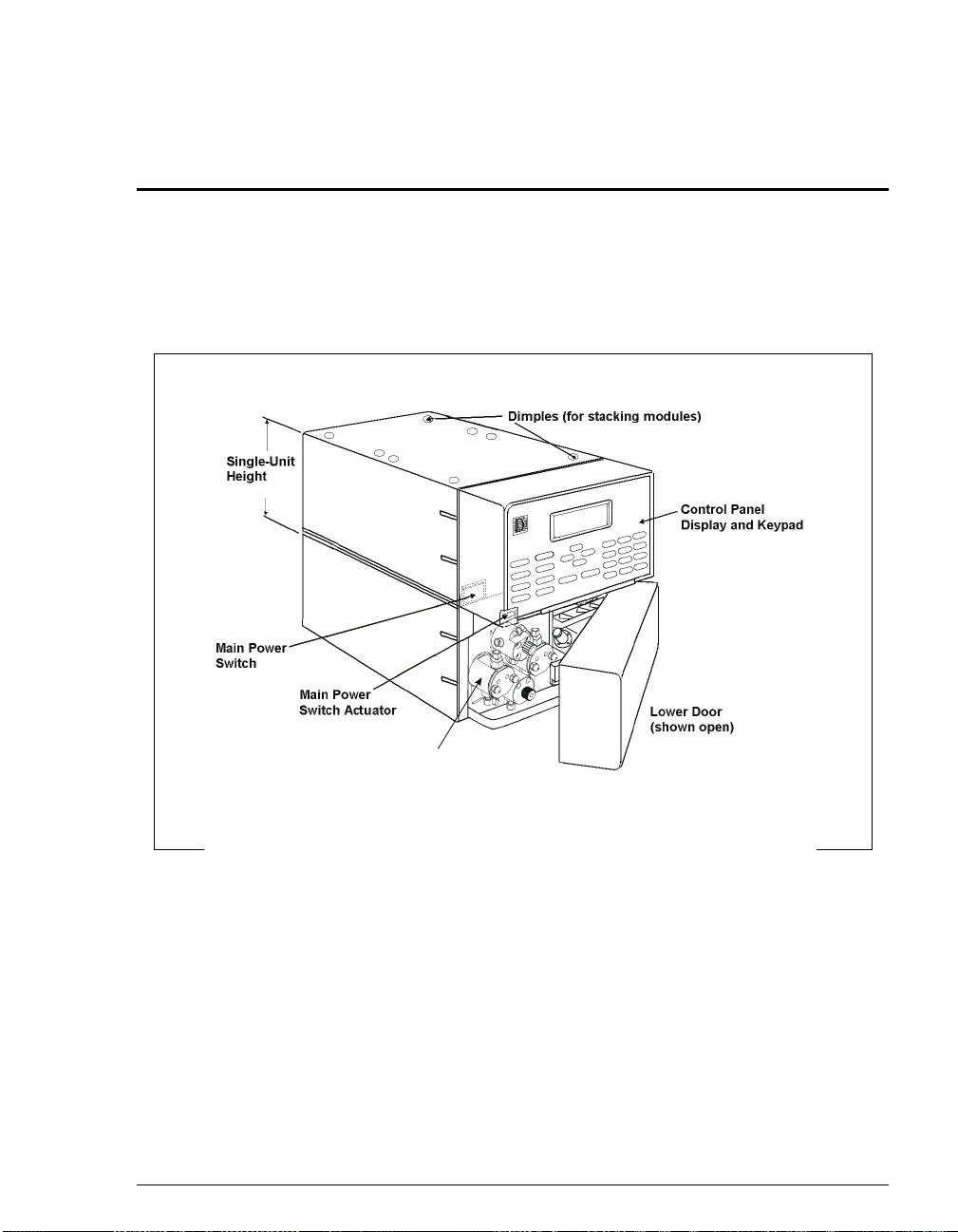
The GP50 Gradient Pump consists of two units (see Figure 2-1). The upper unit
houses the electronics components and the lower unit houses the pump heads and
other mechanical pump assemblies.
Doc. 031377-03 7/01
Pump
Heads
Figure 2-1. GP50 Enclosure
2-1
Page 14

GP50 Gradient Pump
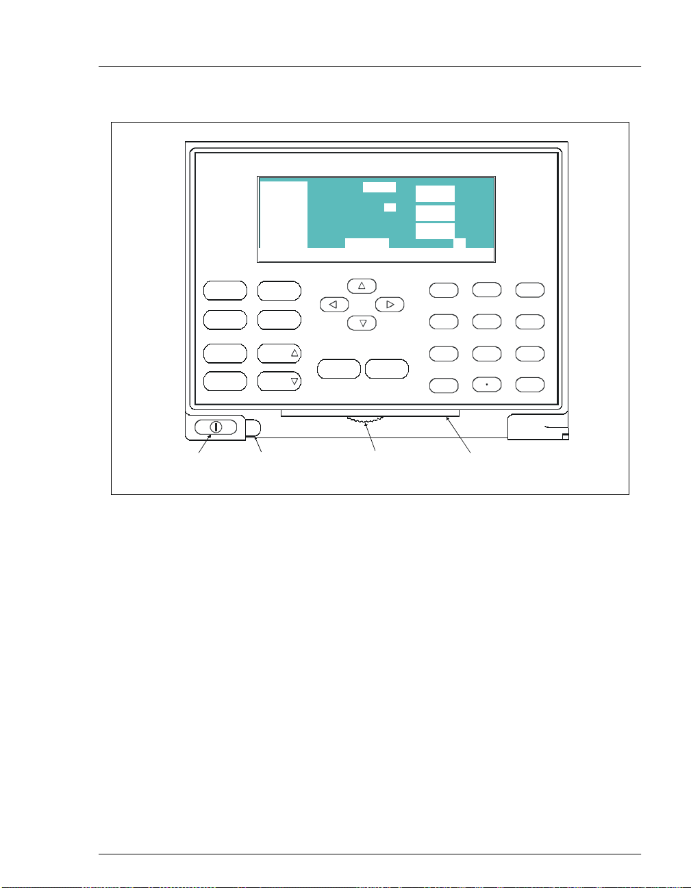
2.1 Front Control Panel
The control panel on the upper door of the pump enclosure contains a liquid
crystal display (LCD), a membrane keypad, and the actuator for the main power
switch (see Figure 2-2). The door opens to provide access to the electronics
chassis (see Section 2.2).
NOTE If no keypad buttons are pressed within a two-hour
period, the front panel backlight will automatically turn
off. To restore the backlight, press any button.
Screen Contrast
Information is displayed on the LCD, also called the
contrast, use the knurled knob in the recess below the keypad (see Figure 2-2).
Tilt Panel
To maximize visibility, the front control panel can be tilted to four different
positions. To tilt the panel, support the door at the left side (to prevent it from
opening) and lift firmly on the tab in the middle of the recess below the keypad
(see Figure 2 -2). Push on the tab t o return the panel to its vertical position.
. To adjust the screen
screen
2-2
Power Switches
The main powe r swit ch is on the bulkhead behind the uppe r door (see Figur e 2-1).
An actuator for the main power switch is on the outside of the front door, at the
lower left corner (see Figure 2-2).
The actuator functio ns only when the door is fully clos ed. Whe n the door is open,
press the main power switch on the bulkhead to turn the module off and on.
To prevent damage to the pump circuitry and components,
always wait at least 15 seconds after powering down before
turning on the power again.
Doc. 031377 -03 7/01
Page 15
GP50 G radient Pump
100.0 %A
0.0 %B
0.0 %C
0.0 %D
Help Message
LOAD
COLUMN A
2000
2.00
LOCAL 2
10.27
METHOD
2•Description
PSI
m L /MIN
MIN
Off/O n
Prime Reset
Insert
Delete
Ma in P o wer
Sw itc h A c tu a to r
Hold/Run
Select
Select
Tab
(for opening
the door)
Help Menu
Figure 2-2. GP50 Display and Keypad Layout
2.1.1 Control Panel Keypad
Use the keypad to directly control pump operation, as well as to create
and modify programmed series of timed events, called
summary:
Press
_
_
To go from a menu to a screen, press the numeric button that
corresponds to the screen’s number on the menu, or move the cursor
to the desired screen name and press
to display a list of available screens.
Menu
Knob
(for adjusting
the contrast)
7
4
1
0
Enter
8
5
23
Tab
(for tilting
the panel)
9
6
Enter
methods
.
. In
Doc. 031377-03 7/01
Only fields shown in reverse video on a screen can be edited. Other
_
fields display information only.
To edit a value in a reverse video field, use the four directional arrow
_
buttons to move the cursor to the field. Use the numeric buttons to
2-3
Page 16
GP50 Gradient Pump
enter variable values, or use the
choose from among predetermined options.
Select
∆
and
Select
buttons to
∇
Keypad
Buttons
To confirm the selected value, press
_
some screens or screen fields, pressing
NOTE A high-pitched beep sounds when you press a
button. When an error occurs, this beep is lower in
frequency. The beeps can be disabled from the
MODULE SET-UP
Function
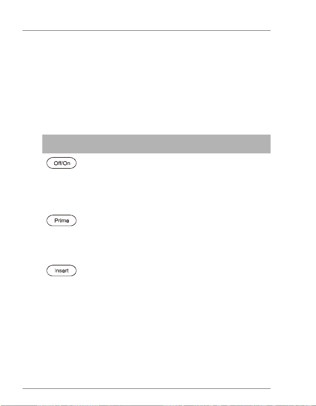
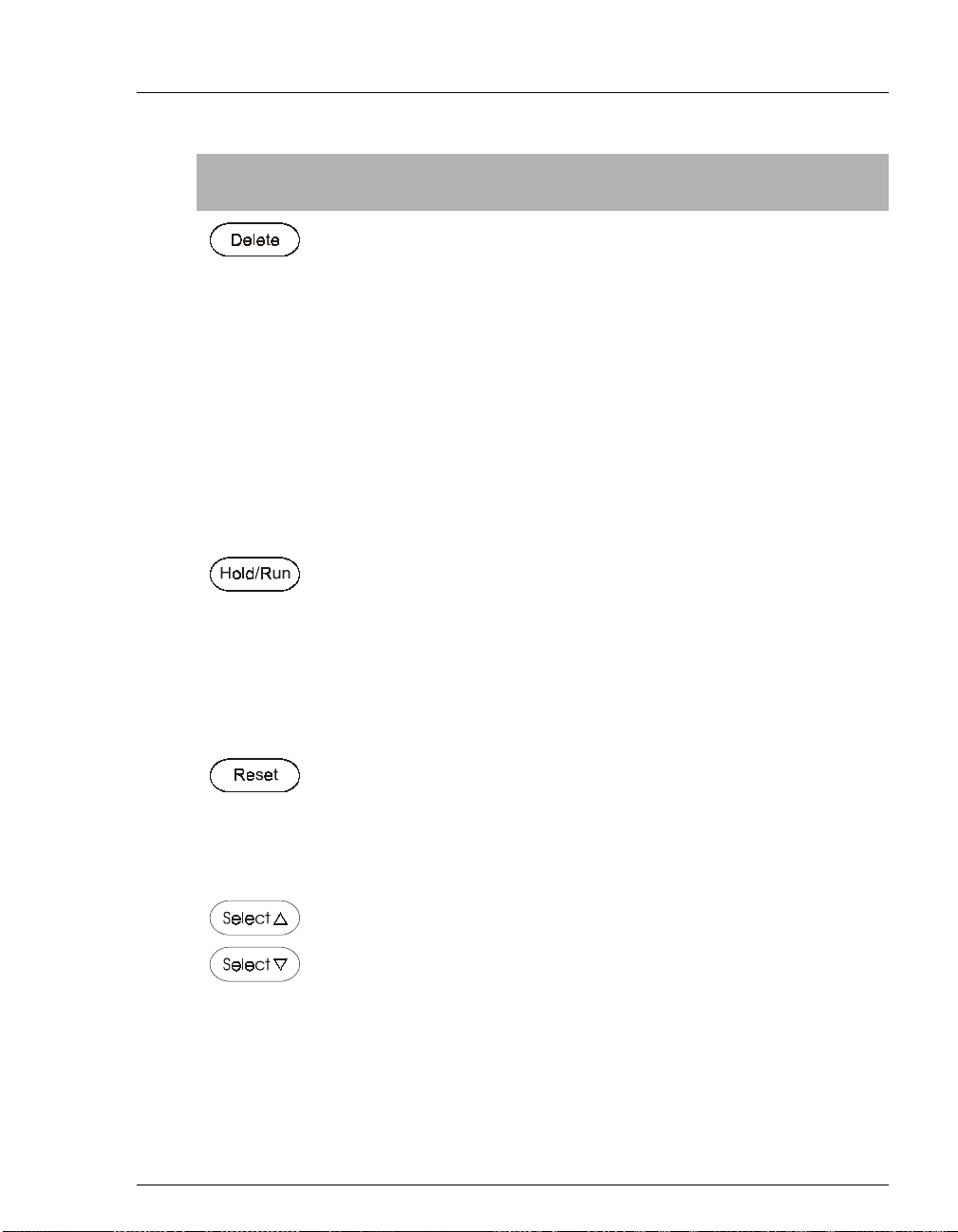
Turns the pump motor off and on.
In Direct control (see Section 2.9), turnin g on the m otor cause s it to
pump isocratically using the displayed eluent percentages and flow rate.
In Method control (see Section 2.9.3), turning on the moto r causes it to
pump at the eluent percentages and flow rate for the elapsed time of the
selected method, or at the initial conditions (when the method clock is at
).
INIT
This button is used when priming the pump heads.
pump to run at maximum vo lume (2.5 mL/min, microb ore; 10.0 mL/min,
standard bore). If the pump motor is off when
pump automatically turns on. To exit priming and return to the normal
flow rate, press
See Section B.2.8 for detailed priming in str uctions.
Prime
screen (see Section C.1.7).
again or press
or an arrow button. In
Enter
is required.
Enter
Prime
is pressed, the
Prime
Off/On
to turn off the pump motor.
causes the
2-4
Inserts a new step into a method. This button functions only when the
cursor is in a
1. Move the cursor to the
added below the cursor position. Parameter values in the new step
are blank.
2. Fill in the time value and press
Note:
time value, the inserted step is not saved because it is incomplete.
3. Insert steps in any order. When you press
automatically reorganized in the correct chronological order.
TIME
field on the
If you move the cur sor out of the
Table 2-1. GP50 Front Panel Buttons
METHOD
field and press
TIME
METHOD
or
or a cursor arrow button.
Enter
TIME
Enter
extension screen.
. The new step is
Insert
field before entering a
, they will be
Doc. 031377 -03 7/01
Page 17
2•Description
Keypad
Buttons
Function
Removes the value from the current entry field. To restore the previous
value, move the cursor from the field before entering a new value.
Pressing
screen “blanks” the step parameter value. Moving the cursor to another
field does not restore the previo us v alue; ins tead, the step remains blank,
indicating no change from the previous step.
To delete an entire method step:
1. Position the cursor in the method’s time field and press
2. Press
Turns the method clock off (
only when the pump is under Method control (see Section 2.9.3).
When the method clock is in Hold, pressing
at either the initial step of a new method or, if resuming an interrupted
method, at the time at which the clock was put in Hold.
When the method clock is in Run, pressing
this “holds” the method and freezes the current conditions.
Delete
time is removed and the help line prompts you to press
again to delete the step.
parameters, press any button except
when the cursor is in a step entry field o n the
Delete
again. Or, to restore the original time and step
.
Delete
) and on
Hold
(Run)
Hold/Run
Hold/Run
METHOD
. The
Delete
Delete
. This button functions
starts the clock
stops the clock;
Doc. 031377-03 7/01
Changes the method clock time to
specified by the method to occur. This button functions only when the
GP50 is under Method control (see Section 2.9.3).
If the method is running, it continues running. If the method is in Hold,
the method clock executes the initial conditions and holds.
When the cursor is positioned at a field with predetermined parameters,
these buttons cycle through the options. In fields with predetermined
numeric values, pressing
pressing
Select
Enter
button increases (or decreases) the value continuously. Press
or a cursor arrow button to confirm the selected value.
Table 2-1. GP50 Front Panel Buttons (Continued)
∇ decreases the value by one unit. Holding down a
Select
Select
, causing the initial conditions
INIT
∆
increases the value by one unit;
2-5
Page 18
GP50 Gradient Pump
Keypad
Buttons
Function
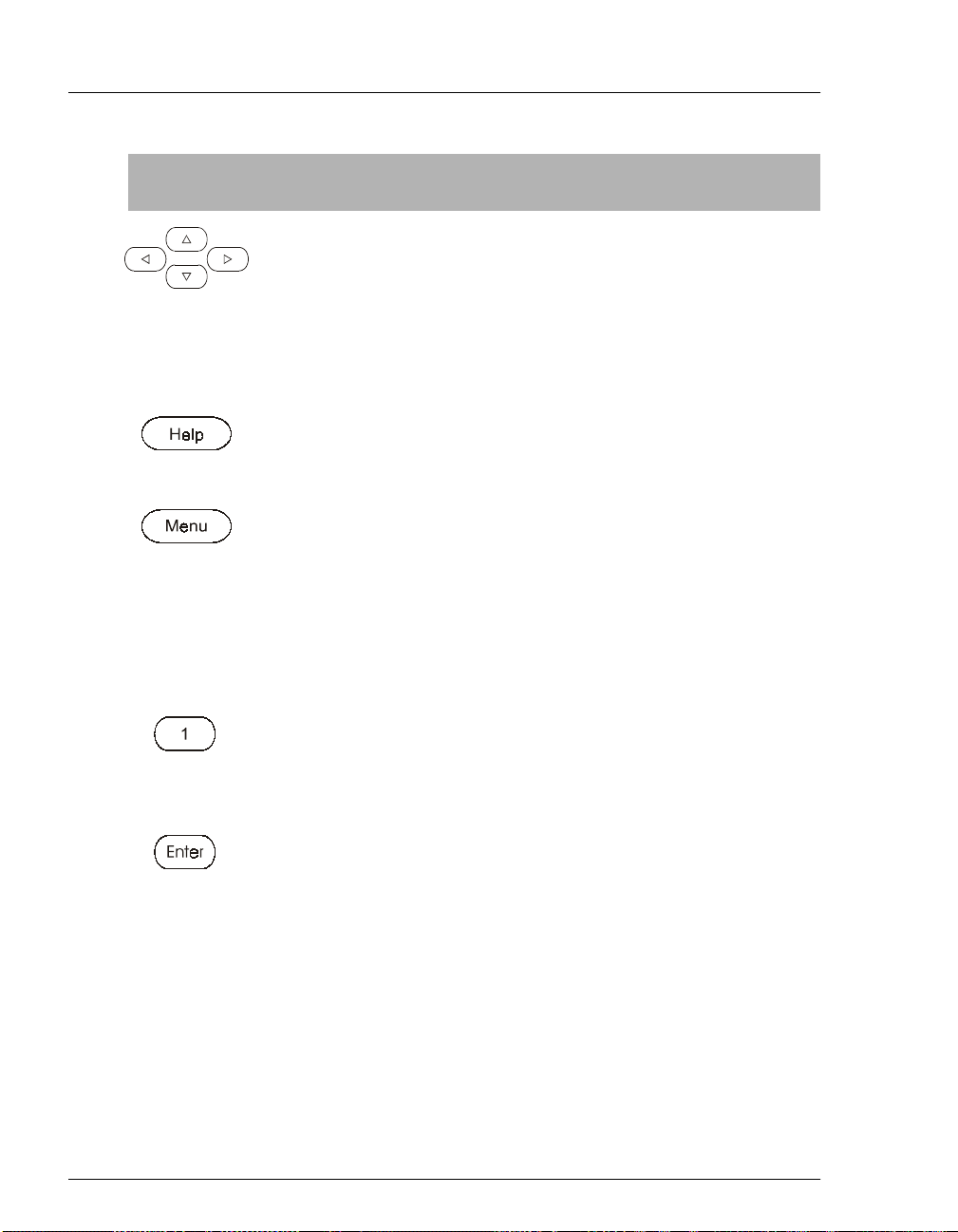
The four cursor buttons move the cursor, in the direction of the arrow, to
the next entry field. If there is no changeable field in that direction, the
cursor moves diagonally or remains in its current location.
In most cases, after entering a new value in an entry field, pressing an
arrow button saves and/or executes the change. The exceptions are the
field, the
METHOD SAVE TO
command, the
Displays a help screen with information pertaining to the current entry
field.
Displays one of three menus, depending on the current screen:
_
From an operational screen, pressing
SCREENS
_
From a diagnostic screen, pressing
DIAGNOSTIC MENU
From a calibration screen, pressing
_
CALIBRATION MENU
Enters numeric values into the current entry field. The numeric buttons
are 0 through 9 and the decimal.
DIAGNOSTIC TESTS
.
METHOD RUN
.
.
screen, and all menu screens.
Menu
Menu
Menu
any calibration
field,
displays the
displays the
displays the
MENU of
2-6
From a menu screen, press ing a nu meri c b utt on open s t he co rres pon ding
screen.
Saves and/or executes changes made in entry fields. If a menu screen is
displayed, pressing
Table 2-1. GP50 Front Panel Buttons (Continued)
opens the highlighed screen.
Enter
Doc. 031377 -03 7/01
Page 19

2.1.2 Display Screens
When the pump has successfully powered-up and passed all diagnostic
tests, the
the
power-up, the
screen. See Section C.2.7 if this occurs.
POWER-UP
screen (see Figure 2-4). If one of the diagnostic tests fails at
MAIN
DIAGNOSTIC TEST
2•Description
screen (see Figure 2-3) displays briefly, followed by
screen displays instead of the
MAIN
NOTE
Help Message
The
selecting the screen from the
(see Section C.2.1).
GP50 GRADIENT PUMP
Figure 2-3. Power-Up Screen
100.0 %A
0.0 %B
0.0 %C
0.0 %D
Help Message
POWER-UP
screen can be viewed at any time by
PUM P H EA D VO LUM E 100 uL
MODULEWARE REV n.nn
B IO S R E V n.n n
LOAD
2000
COLUMN A
2.00
10.27
LOCAL 2
METHOD
DIAGNOSTIC MENU
PSI
mL /MIN
MIN
Doc. 031377-03 7/01
Figure 2-4. Main Screen
The
allow viewing from a d istance. Use the
parameters, such as the flow rate and the percentages of eluents to run.
T o access oth er GP50 screens, pre ss the
of SCREENS
screen displays status information in enlarged char acters to
MAIN
screen to select operating
MAIN
button to displ ay th e
Menu
(see Figure 2-5).
MENU
2-7
Page 20
GP50 Gradient Pump
There are two ways to select a screen from a menu:
Press the numeric button on the front panel keypad that corresponds
_
to the screen number on the menu. For example, p re ss 3 to di splay th e
METHOD
Move the cursor to the field containing the screen number and press
_
Enter
See Appendix C for a description of each screen.
screen.
.
MENU of SCREENS
1
M AIN S CR E EN
2
DETAIL SCREEN
3
METHOD
4
DEGAS OPTIONS
Help Message
Figure 2-5. Menu of Screens
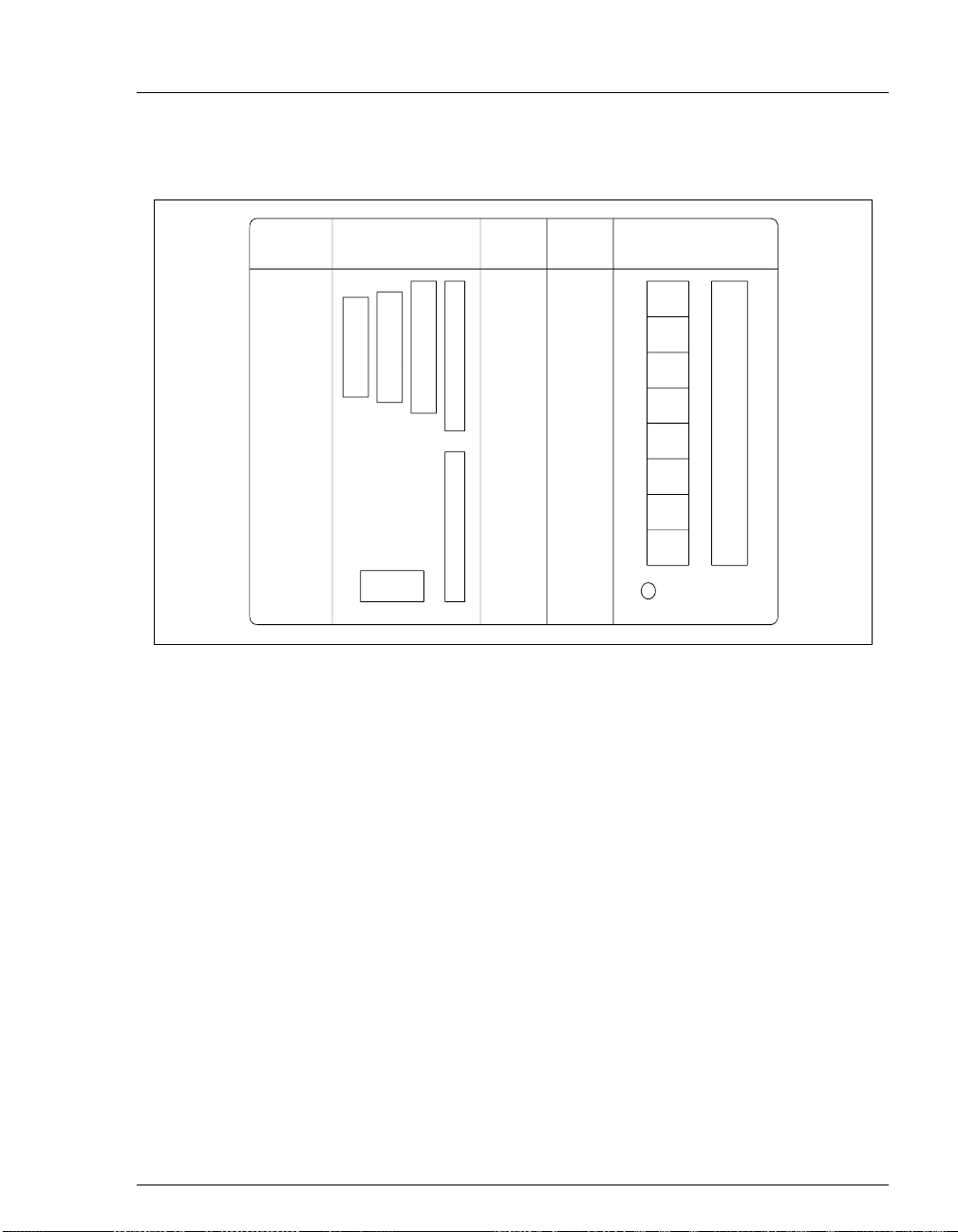
2.2 Electronics Chassis
The electronics chassis is located behind the upper door of the pump enclosure.
The chassis includes se v eral ele ctronics car ds (printed ci rcuit boards) that are used
to control the pump. Connectors on the cards also allow communication between
the pump and other Dionex chromatography modules. Figure 2-6 shows the
electronics components with the upper door open. To open the door, pull on the
tab located to the right of the main power actuator (see Figure 2-2).
Do not remove any of the electronics cards from the pump.
There are no user-serviceable components on the cards. If
servicing is required, it must be performed by qualified
personnel and appropriate electrostatic discharge (ESD)
handling procedures must be followed.
5
MOD ULE SET-UP
PUMP OPTIONS
6
7
TIME FUNCTION IN
8
DIAGNOSTIC MENU
2-8
Ne retirez aucune des cartes électroniques de la pompe. Auc un
des composants sur les cartes ne peut être réparé par
l'utilisateur. Toute réparation doit être effectuée par un
personnel qualifié utilisant des procédures correctes de
décharge électrostatique.
Doc. 031377 -03 7/01
Page 21
2•Description
PWR SPY
L
C
L
E
A
K
GP50/IP25-DSP130W
DIST
MOTOR
SLOT 2SLOT 1
BLANK
D
L
C
C
O
M
M
P6
I
L
S
C
T
A
1
I
3
R
P
I
N
P7
D
I
S
T
1
2
P
I
N
P8
SLOT 3
BLANK
SLOT 4
LAN-000K
RLY-1
OUT
RLY-2
OUT
+
TTL-1
-
OUT
+
TTL-2
-
OUT
+
TTL-1
-
IN
+
TTL-2
-
IN
+
TTL-3
-
IN
+
TTL-4
-
IN
POWER SUPPLY
GREEN - OK
RED - FAULT
SLOT 5
CPU/RLY
F
R
O
N
T
P
A
N
E
L
Figure 2-6. GP50 Electronics Chassis
(Located behind pump door)
LC LEAK
The leak control cable from the LC10 Chromatography Organizer or
LC20 Chromatography Enclosure, connects t o the
LC LEAK
connector in
slot 1. When a leak occurs i n the LC10 or LC2 0 it is re ported to t he GP50.
Doc. 031377-03 7/01
NOTE The LC25 Chromatography Oven and LC30
Chromatography Oven do not connect to the GP50
LEAK
connector. These ovens contain internal leak
LC
control electronics.
LC COMM
The LC30 Chromatography Oven's RJ-11 serial cable connects to the
connector in slot 1. When connected, the LC30 can be remotely
COMM
controlled by the PeakNet workstation.
LC
2-9
Page 22

GP50 Gradient Pump
LC AIR
The cable from the ai r soleno id v alv es in t he LC10, LC20, L C25, or LC3 0
chromatography module conne cts to the
connected, the GP50 can electrically actuate the solenoid valves that
control the position of the injection valve and the optional column
switching valve in the chromatography module.
LC AIR
connector in slot 1. When
To select the valve positions, go to either the
Section C.1.2) or the
TTL/RELAY
METHOD
screen (see Section C.1.4).
MAIN
screen (see
A strip of eight relay and TTL connectors is located in slot 4. These
connectors interface with Dionex and non-Dionex modules for relay and
TTL control of the pump. Appendix D describes the relay and TTL
functions and the connections between the GP50 and other modules.
CPU
Control Moduleware for the pump resides on the CPU/Relay cards.
The CPU logic and Relay I/O cards occupy slot 5. The Relay I/O card
rides piggybac k o n t he CPU card and exten ds over the f ro nt of slot 4. The
card is short enough to allow the optional DX-LAN pump interface card
(P/N 044195) to mount behi nd it in slot 4. A 60- pin ri bbon cab le lin ks the
CPU logic to the display and keypad. The logic monitors the internal
power supply outputs, and reports the status on the multicolored LED at
the bottom of slot 4.
Green indicates normal operation.
_
Red indicates a power fault. The GP50 will enter its diagnostic state
_
and inhibit all other cont rols unti l the f ault is corr ected . If this occurs,
turn off the power for a few seconds and then turn it back on.
2-10
Doc. 031377 -03 7/01
Page 23

2.3 Mechanical Chassis
The mechanical chassis is housed in a pull-out drawer located behind the lower
door of the pump enclosure. The front of the chassis contains the components
described in Section2.4. Other mechanical assemblies are located inside the
chassis drawer. The drawer should be pulled out only for service procedures. For
routine operation, push in the drawer and tighten the lock located on the lower
right corner of the chassis.
Observe the warning label on the inside of the lower door. The
arrows on the label indicate moving mechanical parts that
present pinch hazards when the pump is on and the
mechanical drawer is open. Do not operate the pump with the
mechanical chassis drawer pulled out.
Respectez l'étiquette d'avertissement apposée à l'intérieur de
la porte inférieure. Les flèches sur l'étiquette indiquent des
pièces mécaniques mobiles qui posent un danger de
pincement lorsque le GP50 est sous tension et le tiroir
mécanique est ouvert. N'ut ilisez jamais le GP50 avec le tiroir
du châssis mécanique ouvert.
2•Description
Doc. 031377-03 7/01
2-11
Page 24
GP50 Gradient Pump
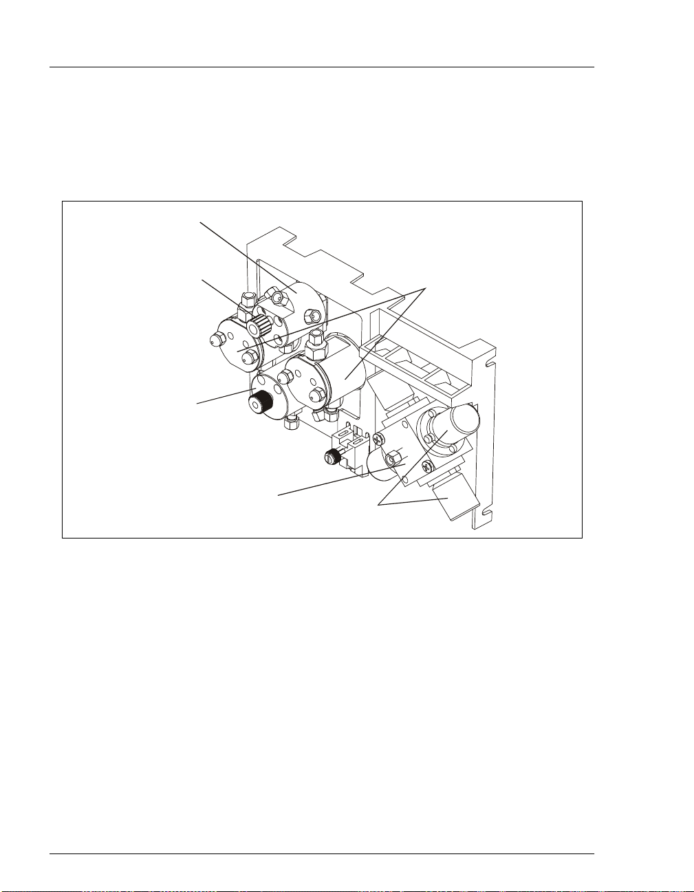
2.4 Mechanical Components
Figure 2-7 shows the mechanical componen ts located behi nd the lo wer door of the
enclosure.
Pressure
Transducer
Pressure
Transducer
Waste Valve
Pr im ing
Block
Pump
Heads
2-12
Eluent
Manifold
Proportioning
Figure 2-7. GP50 Mechanical Components
Doc. 031377 -03 7/01
Page 25
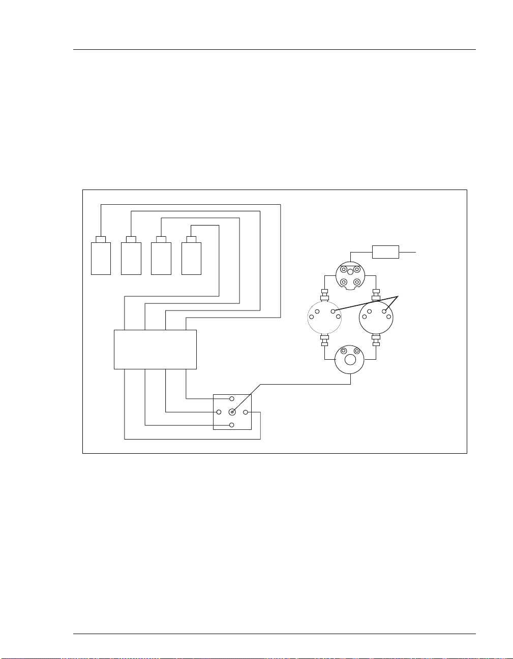
2.4.1 Pump Eluent Manifold
Eluent lines A through D are routed through the rear of the GP50 to the
vacuum de g as pump ( if ins ta ll ed) (see Sec ti on 2.5) and then to the rear of
the proportioning valve. If the vacuum degas pump is not installed, the
eluent lines are connected directly to the proportioning valve. The proper
proportion of eluent exits the front of the valve and is directed to the
priming block. Figure 2-8 shows the eluent flow path through the system.
2•Description
Eluent Reservoirs
VAC Chamber IN
VAC Chamber OUT
ABCD
Pump H eads
OUT
D
Proportioning Valve/
A
C
Manifold Assembly
B
Pressure
Transducer
Figure 2-8. Eluent Flow Schematic
Mixer To Column
Rinse Ports
Priming Block
Doc. 031377-03 7/01
2-13
Page 26

GP50 Gradient Pump
2.4.2 Pump Heads
There are two types of pump heads: standard bore and microbore. The
table below summarizes the features and operating conditions for each
type.
Pump Head
Type
Standard
Bore
Microbore 25µL Isocratic and
*Flow rates are adjustable in increments of 0.01 mL/min.
NOTE Although there is some overlap in flow rates
Piston
Volume
100µL Isocratic 0.04–10.0 35 MPa
between the two pump configurations, continuous
operation of the microbore pump at flow rates
above 2.0 mL/min will decrease seal and pump life.
For the best extended operation at 2.0 mL/min or
above, use a standard bore pump. To achieve
optimum performance at flow rates below
0.4 mL/min, use a microbore pump.
Pump
Operation
Gradient 0.4–10.0 35 MPa
Gradient
Flow Rate
(mL/min)*
0.0–2.50 35 MPa
Maximum
Operating
Pressure
(5000 psi)
(5000 psi)
(5000 psi)
2.4.3 Pump Mixers
A pump mixer ensures complet e mixi ng of the proportioned eluents prior
to injection. The mixer is installed between the pump outlet and the
injection valve. Three types of mixers are available:
_
_
_
2-14
In standard bore PEEK pumps, a GM-5 Mixer (P/N 054044) is used.
In microbore PEEK pumps, a GM-4 Mixer (P/N 049136) is used.
In stainless ste el pumps , a Sta inles s Ste el Mi x er (P /N 0 54043) is use d.
Doc. 031377 -03 7/01
Page 27

2.4.4 Pump Priming Block
The priming block “tee” directs the flow of eluent fr om the manifo ld i nto
the pump heads. The priming block is also used for rapid removal of air
from the system.
Refer to Section B. 2.8 for instructions on priming the pump heads.
2.4.5 Pressure Transducer
From the priming block, the liquid stream is directed to the inlet check
valves on the pump heads, through the pump heads, and finally through
the outlet check valves to the pressure transducer.
Flow from the outlet check valves on the pump heads is combined in the
pressure transducer. The pressure transducer measures the system
pressure at this point. The interactive constant-flow/constant-p ressure
control program on the DSP precisely controls the pump motor speed to
assure flow rate accuracy.
A waste line exits the bottom of the pressure transducer. Opening the
valve on the pressure transducer diverts flow to the waste line and relieves
system pressure, forcing air out of the system.
2•Description
Doc. 031377-03 7/01
Flow output from the pressure transducer is directed out of the pump
module, through the gradient mixer, and on to the rest of the
chromato graphy system (inj ection valve, column, detector).
See Section B.2.6 for eluent outlet line connections.
2-15
Page 28

GP50 Gradient Pump
2.5 Vacuum Degas Pump Assembly (Optional)
The Dionex vacuum degas pump provides continuous on-line vacuum degassing
of up to four eluents. The assembly, which must be installed at the factory,
consists of :
A 4-channel degas chamber (with degas membranes) with 17 mL internal
_
capacity p er channel
A dual-stage diaphragm vacuum pump
_
A solenoid valve
_
An on-board vacuum sensor
_
The electronics required to operate the vacuum pump
_
Fittings, tubing, and other accessories
_
By default, the de gas pump tur ns on f or 2 minu tes when th e GP50 power is turned
on. Thereafter, the pump turns on for 30 seconds at 10-minute intervals. The
DEGAS OPTIONS
Section C.1.6). You can check the vacuum chamber pressure from the
STATUS
screen (see Section C.3.4).
screen allows you to change the cycle time and duration (see
DEGAS
NOTE All components of the vacuum degas assembly are made
of inert materials or corrosion-resistant materials.
However, Dionex recommends thoroughly flushing any
chemicals out of the tubing with deionized water after
each use to avoid crystallization in the membrane pores.
2.6 Piston Seal Wash (Optional)
When using highly concentrated buffer solutions, Dionex recommends
continuously rinsing the piston seal with a piston seal wash. Rinsing removes salt
crystals that may abrade the piston, thereby causing the seal to wear out
prematurely and allow leaks.
Dionex offers a continuous seal wash kit (P/N 059187) for the GP50. For
installation instructions, see Section B.2.8 or the instructions included with the
kit.
2-16
Doc. 031377 -03 7/01
Page 29
2.7 Eluent Reservoirs
NOTE Dionex strongly recommends degassing all eluents and
storing them in reservoirs pressurized with helium. This
helps prevent bubbles (resulting from eluent outgassing)
from forming in the el uent proportionin g valves, pump
heads, and the detector cell.
Degassed eluents and pressurized reservoirs are
especially important when combining aqueous and nonaqueous components (e.g., water and methanol).
Pressurizable reservoirs allow eluents to be stored under
a specific atmosphere.
The following pressurizable reservoirs are available from Dionex:
1-liter glass reservoirs with shatterproof plastic coating (P/N 044126)
_
2-liter glass reservoirs with shatterproof plastic coating (P/N 044127)
_
1-liter plastic reservoirs (P/N 044128)
_
2•Description
2-liter plastic reservoirs (P/N 044129)
_
Do not use the 2-liter plastic reser voir (P/N 044129) for off-line
vacuum degassing of eluents. The reservoir was not designed
for this purpose.
N'utilisez pas le réservoir en plastique de 2 litres (N /P 044129)
pour le dégazage à vide hors ligne d'éluants. Le réservoir n'a
pas été conçu à cette fin.
Refer to the
Pressurizable Reservoir Installation Instructions
(Document No.
034581) for installation details.
EO1 Eluent Organizer (Optional)
The Dionex EO1 Eluent Organizer (P/ N 044 125) holds eluent reservoirs in a liner
that contains spills and leaks. The EO1 can also be used to pressurize reservoirs.
Up to two optional E01 Eluent Organizers can be places on top of the system
Doc. 031377-03 7/01
2-17
Page 30

GP50 Gradient Pump
enclosure. Each organizer can accommodate one or two reservoirs, depending on
the type of reservoir used (see the table below).
No. of
Reservoirs
2 1-Liter glass or plastic 2 L
2 2-Liter plastic 4 L
1 2-Liter glass 2 L
Description Total Volume
2.8 Rear Panel
The rear panel contains the main power receptacle and fuses. It also includes a
DX-LAN connector for interfacing the GP50 with the PeakNet workstation. The
rear panel is illustrated in Figure B-1.
2.9 Functional Description
2.9.1 Operating and Control Modes
The operating mode determines
commands:
_
In Local mode, the GP50 receives commands from the front control
panel buttons and screens.
in Liters
how
the GP50 receives operating
2-18
In Remote mode, PeakNet 5 software sends commands from the host
_
computer via the DX-LAN int erfac e. Limited o perating changes fr om
the front panel are allowed.
_
In Locked Remote mode, PeakNet 5 or PeakNet 6 software sends
commands from the host computer via the DX-LAN interface. All
operating changes from the f ront pane l are disab led. When PeakNet 6
software is controlling the GP50, the pump is always in Locked
Remote mode.
The control mode determines
_
In Direct control, the GP50 exe cutes commands immediately.
when
operating commands are executed.
Because there is no time-ba sed program, th e method clock i s not used
and the
Hold/Run
and
buttons do not operate.
Reset
Doc. 031377 -03 7/01
Page 31

2•Description
_
In Method control, the GP50 executes commands according to the
timed steps in a method. The method is programmed from the GP50
front panel or from PeakNet 5 software. See Section 2.9.3 for details
about Method control from the front panel.
using PeakNet 5 to program and run methods, refer to the onli ne Help
or user’s guide.
The table below summarizes the various operating and control mode
configurations. Select the modes from the
Section C.1.2),
DETAIL
screen (see Section C.1.3), or chromatography
software.
Operating/Control Mode Pump Operat ion
Local/Direct Control Commands are entered from the GP50 front control
panel and executed immediately after being entered.
Local/Method Commands are entered from the GP50 front control
panel and executed by running a method programmed
from the front panel.
Remote/Direct Control Commands are sent from PeakNet 5 and executed
immediately when received.
For information about
screen (see
MAIN
Locked Remote/Direct
Control
Remote/Method Commands are sent from PeakNet 5 and executed by
2.9.2 Local and Remote Modes
Local Mode
When the GP50 power is turned on, the pump is in Local mode. In Local
mode the pump accepts operating commands from two sources:
_
Direct input from the front panel keypad and screens. With direct
input, all GP50 operating functions are available.
_
TTL inputs from a remote controller (for example, a Dionex detector
module or autosampler). TTL signals can be used to turn the pump
motor on and off, turn the method clock on and off, and increment or
decrement the method number.
Doc. 031377-03 7/01
Commands are sent from PeakNet 5 or PeakNet 6 and
executed immediately when received.
running a method programmed in PeakNet 5.
2-19
Page 32

GP50 Gradient Pump
Remote Mode
In Remote mode, PeakNet 5 software sends operatin g commands fr om the
host computer via the DX-LAN interface. In Remote mode, operating
parameters can be changed from the front panel, provided they do not
interfere with a running method.
Locked Remote Mode
In Locked Remote mode, PeakNet 5 or PeakNet 6 software sends
operating commands from the host computer via the DX-LAN interface.
In Locked Remote mode, all operating changes from the front panel are
disabled.
When the GP50 is controlled by PeakNet 5, select the Locked Remote
Start option from the PeakNet 5 Run program to operate in the Locked
Remote mode. To return the GP50 to Local mode, clear the Start opt ion or
turn the GP50 power off and then on.
When the GP50 is controlled by PeakNet 6, connecting to the PeakNet 6
timebase automatically selects the Locked Remote mode. To return the
GP50 to Local mode, either clea r the Connect check box on the PeakNet 6
control panel or turn the GP50 power off and then on.
2.9.3 Method Control
In Method control, commands are executed according to the time-based
steps programmed in a method. Each step specifies the eluent
composition and flow rate to be delivered by the pump at a given time.
The selected eluent mixture is delivered either isocratically, or as a
multistep linear or curved gradi ent. As the method runs, the GP50
calculates the changes i n eluent compositio n require d to deli v er a gradient
from one method step to the next or to match the selected curve.
2-20
Doc. 031377 -03 7/01
Page 33

2•Description
Methods are programmed, saved, and edited from the
METHOD
(see Figure 2-9). See Section 3.3 for programming instructions.
M E TH OD E DIT
SAVE TO RUN 100605
LIMITs 0 - 5000
TIME % A
IN IT
0.00
123.45
345.67
25.0
100.0
10.0
17.2
25.0
0.0
22.2
19.6
25.0
0.0
32.3
33.2
25.0
0.0
35.5
30.0
V
C%B %C %D
L1.00
0
I
L
5
FLOW
2.00
Help Message
Figure 2-9. Method Screen
NOTE For information about using PeakN et 5 to program and
run methods, refer to the online Help or user’s guide.
Here is a summary of basic information about using methods.
Each method can contain up to 50 time-based steps. Step 1 always
_
starts at
The GP50 can store up to 100 separate methods (0 through 99) in
_
(initial condition). Step 2 always starts at
INIT
memory. Methods are retained in memory even after the pump is
powered down.
PSI
>
>
>
>
TIME = 0.0
screen
.
Doc. 031377-03 7/01
The total number of methods that can be stored in memory
depends on the length of each method and the amount of
available memory; thus, the actual total may be less than 100.
The pump can run under method control while you are entering or
_
editing any method.
When you save changes to the currently running method or switch to
_
a different method, the method clock continues running unaffected.
Only those parameter changes which affect the method
after
the
current time will be implemented in the current run.
2-21
Page 34
GP50 Gradient Pump
2.9.4 Eluent Delivery
Isocratic Eluent Run
The simplest use of the GP50 is for the delivery of an isocratic
(unchanging) mixture of one or more eluents. If more than one eluent is
selected, the pump d elivers a proport ional mixt ure of the el uents based on
the percentage of each eluent selected. The combined percentages of all
eluents selected must total 100% or the pump will not run.
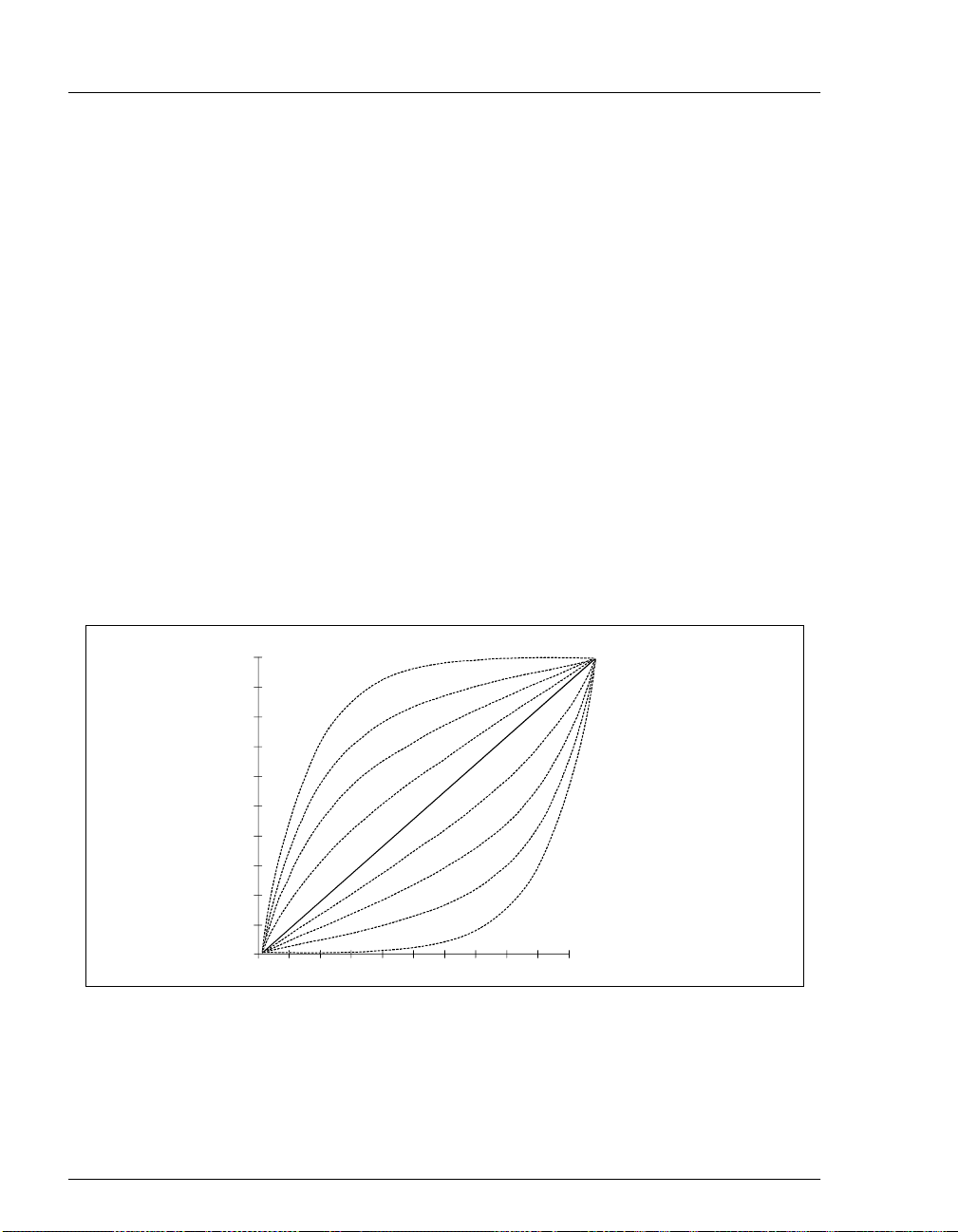
Gradient Eluent Run
The GP50 can produce step, linear, concave, or convex curves in eluent
concentration over a specified time period. The slope of the gradient is
determined by the selected gradient curve (see Figure 2-10) and the time
between the starting and end ing points of a grad ient step. It is important to
note the following points:
The curve number p arameter determines whethe r the pump deliver s a
_
linear or curved gradient.
2-22
1.0
.9
.8
.7
.6
.5
.4
.3
.2
.1
0
1
0
1
2
3
4
5
6
7
8
9
2
45678
3
910
Figure 2-10. Eluent Composition Profile for Curves 1 - 9
Doc. 031377 -03 7/01
Page 35

2•Description
Curve numbers are defined as follows:
Curve Number Gradient Type
1, 2, 3, 4 Convex
5 Linear (power-up default)
6, 7, 8, 9 Concave
NOTE A curve number in a step instructs the pump to use
the selected curve number when moving from the
previous step to that step. Because there are no
previous steps for
cannot be entered for these steps.
The gradient slope does not change during a step if curve 5 (the
_
INIT
default setting) is selected, because curve 5 represents a linear
gradient.
Convex curves cause rapid changes in eluent composition at the
_
beginning of the curve and slower changes at the end. Concave curves
cause slower changes at the beginning and rapid changes at the end.
TIME=0.0
or
, curve numbers
Slope changes o ver time become mor e ex treme as c urves go from 6 t o
_
9 (more concave) and from 4 to 1 (more convex). Figure 2-10 shows
the eluent composition profiles corresponding to curves 1 through 9,
normalized for 0–100% for 10 minutes.
Any consecutive method steps specifying identical eluent
_
compositions will generate an isocratic segment, regardless of the
curve number selecte d.
A step change is a steep linear gradient in which the eluent
_
composition changes from one eluent to another within 6 seconds.
Doc. 031377-03 7/01
2-23
Page 36

GP50 Gradient Pump
2-24
Doc. 031377 -03 7/01
Page 37

3 • Operation and Maintenance
3.1 Getting Ready to Run
NOTE The GP50 Gradient Pump is designed to perform ion
chromatography and BioLC applications only and
should not be used for any other purpose. If there is a
question regarding appropriate usage, contact Dionex.
3.1.1 Degas Eluents
Dionex strongly recommends degassing all eluents and storing them in
reservoirs pressurized with filtered inert gas (see Sect ion 3.1. 3). This
helps prevent bubbles caused by eluent outgassing from forming in the
eluent proportioning valves, pump heads, and the detector cell. Degassed
eluents and pressurized reservoirs are especially important when
combining aqueous and nonaqueous components (e.g., water and
acetonitrile).
The GP50 with the optional vacuum degas pump assembly provides
continuous on-line vacuum degassing of up to four eluents.
Doc. 031377-03 7/01
If the GP50 is not equipped with the vacuum degas assembly, manually
vacuum-degas eluents daily, as described below, and store them in
pressurized reservoirs.
Degassing Eluents Manually
1. Prepare the eluent required for your applicat ion. Pour it into a v acuu m
flask and attach the flask to a vacuum pump or water aspirator.
2. Vacuum degas the eluent for 5-10 minutes by shaking or sonication.
3. Remove the flask from the vacuum.
the aspirator back into the flask.
4. Pour the degassed eluent into a press uriza ble res ervoir . Be car eful not
to shake the e luent.
5. Install end-line filters and press urize the re servoi rs (see Sectio ns 3.1.2
and 3.1.3).
Do not allow water to flo w fr om
3-1
Page 38

GP50 Gradient Pump
3.1.2 Filter Eluents
Always f il t er e lue nt s bef or e beginning operation. Fil ter in g re moves small
particulates that may contaminate the eluent proportioning valves or the
pump check valves and cause erratic flow rates or loss of prime. The
pressurizable reservoir Ship Kits supply end-line filters (P/N 045987) for
this purpose.
Install an end-li ne f il ter on the end of each elu ent li ne insi de the re se rv oir.
To prevent air from being drawn through the lines, mak e sure that the end
of each filter r eaches the bot tom of the el uent reser voi r and that eac h fi lter
is submerged in eluent.
3.1.3 Pressurize Eluent Reservoirs
The GP50 Gradient Pump is capable of operation with or without head
pressure on the eluent. Pressurization of the eluent reservoirs, if used,
should be with filtered inert gas (preferably helium). Refer to the
Pressurizable Reservoir Installation Instructions
1. V erify that a re gu lator (P/ N 046594) is install ed on the g as supp ly line
to the reservoirs.
for details.
3-2
2. Turn on the gas supply and adjust the pressure to 55 KPa (8 psi).
Never pressurize the reservoirs above 69 KPa (10 psi).
Ne mettez jamais les réservoirs d'éluants sous une pression
supérieure à 69 kPa (10 lb/po²) .
Doc. 031377 -03 7/01
Page 39

3.1.4 Start-Up
1. Turn on the main pump switch.
3 • Operation and Maintenance
The
POWER-UP
screen displays (see Figure 2-4). A series of diagnostics tests is
MAIN
run at power -up. If one of the test s fail s, the
screen displays briefly (see Figure 2-3) and then the
DIAGNOSTIC TEST
displays instead. See Section C .2.7 if this occurs.
When the GP50 powe r is turned on, the injection v alv e is initia lized to
the Load position.
2. Press
Off/On
3. Check the pressure reading on the
to start the pump flow.
screen. The GP50 display
MAIN
updates the pressure readout once pe r piston str oke. The rea ding from
one stroke to the next should be within 3%.
A variation of more than 3% indicate s that the pump is out of prime.
Refer to Section B.2.8 for priming instructions, or see Section 4.1 for
other conditions which can cause the pump to lose prime.
NOTE After starting the pump or changing the flow
rate, wait at least 5 minutes (up to 20 minutes
for low flow rates in a standard bore pump)
before beginning an analysis. This allows the
pump's real-time electronic pulse damping
circuitry to stabilize the flow rate.
screen
Doc. 031377-03 7/01
3-3
Page 40

GP50 Gradient Pump
3.1.5 Selecting the Pressure Limits
The high and low pres sur e li mit s aut omat ic all y st op the pump if a sy stem
malfunction occurs, such as overpressurization caused by a blockage or
low pressure caused by a leak downstream from the pump.
When PeakNet is controlling the pump, select the pressure limits
_
from the software.
When the pump is running under Local mode, Direct control, enter
_
the pressur e limits on the
When the pump is running under Local mode, Method control, enter
_
the pressure limits on the
are set in the
When a limit trip stops t he pump, the method c lock immediate ly stops
and goes to Hold. The current status of the program that was running
at the time is displayed on the front panel.
To select the pressure limits from the front panel:
step and remain unch anged t hro ughout the ana lysis .
INIT
DETAIL
METHOD
screen (see Figure 3-1).
screen (see Figure 3-5). The limits
1. Go to the
DETAIL
or
METHOD
screen and move the cursor to the
field.
2. Enter a low pressure limit between 1.4 and 2.8 MPa (200-400 psi).
DETAIL SCREEN
100.0 %A
0.0 %B
0.0 %C
0.0 %D
LOCAL
Help Message
Figure 3-1. Detail Screen: Setting Pressure Limits
2125
2.00
IN J E C T
COLUMN
LIMIT
DIRECT CNTRL
PSI
m L/M IN
SAMPLE
A
300-2500 PSI
TTL1
TTL2
RLY1
RLY200
1
1
The setting may vary, depending on the system operating pressure.
The low pressure limit is activated after 13 pump piston strokes (i.e.,
after 1.3 mL (standard bore) or 0.325 mL (microbore) of fluid is
pumped through).
3. Enter a high pressure limit that is 2.8 to 3.4 MPa (400-50 0 psi ) above
the normal system operating pressure. The pump is equipped with a
pressure limit that prevents operation above 35 MPa (5076 psi).
LIMIT
3-4
Doc. 031377 -03 7/01
Page 41

3 • Operation and Maintenance
3.1.6 Selecting the Operating and Control Modes
1. Go to either the
displays
displays
2. To select the operating m ode:
_
_
3. To select the control mode, move the cursor to the field, press
Select
a cursor arrow button.
LOCAL, REMOTE
DIRECT CNTRL
GP50 is controlled by PeakNet 6
If the
PeakNet 6 timebase a utomatica lly select s
the GP50 to
PeakNet 6 control panel or turn the GP50 power off and then on.
GP50 is controlled by PeakNet 5
If the
on the
Select
Enter
To select
Remote Start option from t he Run program. To return the GP50 to
LOCAL
on
MAIN
or
∆
or a cursor arrow button.
LOCKED RMT
, clear the Start op tion o r turn the GP50 po wer of f and then
.
or
Select
∆
or
MAIN
LOCAL
or
Select
DETAIL
or
, either clear the Connect check box on the
DETAIL
to toggle to the desired mode, and press
∇
to toggle to the desired mode, and press
∇
screen. The operating mode field
, or
LOCKED RMT
METHOD
screen. Move the cursor to the field, press
with PeakNet 5, select the Locked
. See the example in Figure 3-2.
. The control mode field
, connecting to the
LOCKED RMT
select
,
LOCAL
. To return
or
REMOTE
or
Enter
25.0 %B
15.0 %C
0 .0 %D
Doc. 031377-03 7/01
60.0 % A
LOAD
COLUMN A
LOCA L
2000
2.00
DIRECT CNTRL
PSI
m L/MIN
Help Message
Control ModeOperating Mode
Figure 3-2. Main Screen: Operating and Control Mode Fields
3-5
Page 42

GP50 Gradient Pump
3.2 Running Under Direct Control (Local Mode)
Direct Control, Local mode is use d most often when a PeakNet workst atio n is not
configured.
Direct Control Example
Specify an isocrati c mi xture of 60% eluent A, 25% eluent B, and 15% eluent C to
be pumped at 2.0 mL/min (see Figure 3-3).
3-6
1. Go to the
control modes to
Figure 3-4 illustrates the
up.
MAIN
60.0 % A
25.0 %B
15.0 %C
0 .0 %D
Help Message
Figure 3-4. Main Screen: Running Under Direct Control
Figure 3-3. Isocratic Run Profile
or
LOCAL
DETAIL
screen and if necessary, change the operating and
and
DIRECT CNTRL
screen as it wil l appear when the e xa mple is set
MAIN
LOAD
2000
COLUMN A
LOCA L
DIRECT CNTRL
(see Section 3.1.6).
PSI
2.00
m L/MIN
Doc. 031377 -03 7/01
Page 43

3 • Operation and Maintenance
2. Move to the %A field and enter 60; move to the %B field and enter 25; move
to the
eluent percentages equa l 100).
field and press
%C
(15 is automatically filled in to ma ke the
Enter
3. Move to the
mL/MIN
4. If the pump is currently off, press
field and enter 2.
Off/On
to turn on the motor and begin the
isocratic delivery.
NOTE After starting the pump or changing the flow rate, wait
at least 5 minutes (up to 20 minutes for low flow rates in
a standard bore pump) before beginning an analysis.
This allows the flow rate to stabilize.
3.3 Running Under Method Control (Local Mode)
This section pro vi des general instructions on how to create, edit , and run methods
from the GP50 front panel. For step-by-step examples, see Section 3.4.
When entering parameters on the
After starting the pump or changing the flow rate, wait at least 5 minutes (up
_
METHOD
to 20 minutes for low flow r ates in a sta ndard bore p ump) befor e beginning an
analysis. T his allows the flow rate to stabilize.
In the %A, %B, %C, and %D columns, enter decimal percentage values from
_
0.1% through 100% for the eluent compositions. The combined percentages
for all eluents must total 100% or the pump will not run.
In the V column, select the injection valve posi tion (L for load or I for inject).
_
screen, observe these guidelines:
In the
_
increments of 0.01 mL/min. See Section 2.4.2 for the available flow rate
ranges. They vary, depending on the size of the pump head and whether the
run is isocratic or gradient.
For steps other than
_
The curve num ber determines whether the pump delivers a lin ear or curved
Doc. 031377-03 7/01
column, ent er the pump flow rate. Fl ow rates are adjustable in
FLOW
Continuous operation of the microbore pump at flow rates
above 2.0 mL/min will decrease seal and pump life. For
optimum performance above 2.0 mL/min, a standard bore
pump should be used.
INIT
and
TIME=0.0
, enter a curv e number in the C column.
3-7
Page 44

GP50 Gradient Pump
gradient when moving to the step from the one preceding it (see
Section 2.9.4). The default is curve 5 (linear).
NOTE Because there are no previous steps f or
curve numbers are not entered for them.
If a step field is “blank” (has no entry), the last selected value for the field
_
INIT
TIME=0.0
or
remains in effect.
The symbol
_
next to the bottom time ent ry indicates there are addit ional steps
∨
below. Move the cursor to the bottom time entry and press the down arrow to
see the additional step(s).
The symbol ^ next to the top time entry indicates that it is preceded by at least
_
one more step. Move the cursor to the entry and press the up arrow to see the
additional step(s).
The symbol > at the right edge of each line indicates a lateral extension to the
_
line. Move the cursor to the end of a line and press the right arrow to display
the
METHOD
extension screen (see Section C.1.5).
3.3.1 Creating a New Method
You can create a new method when the method clock is in either
.
Run
1. Go to the
MAIN
or
DETAIL
operating and control modes to
Section 3.1.6).
screen and if necessary, change the
LOCAL
and
METHOD
(see
,
Hold
or
3-8
2. Go to the
3. In the
EDIT
METHOD
field, enter the number of the method to be created. This
screen.
can be the number of an unused method or of an existi ng met hod that
you plan to edit and sa v e as a new method. If you enter the number of
an unused method, the screen will look similar to th e example screen
in Figure 3-5.
Doc. 031377 -03 7/01
Page 45

3 • Operation and Maintenance
M ETHO D E DIT
TIME %A
100.0
0.00
Help Message
Figure 3-5. Method Screen: Creating a New Method
4. In the
5
%B %C %D V
field, set the low and high pressure limi ts (see
LIMITs
SAVE TO RUN
LIMITs
5
0 - 5000
C FLOW
_
L1.00IN IT
_
0
PSI
>
>
>
>
Section 3.1.5).
5. Each method starts out with two timed steps (see Figure 3-5): an
initial conditions st ep (contai ning
zero step (containing 0.00 in the
in the
INIT
column). The parameters in
TIME
column) and a time
TIME
each of these first two steps can be changed but the steps cannot be
deleted. Enter the parameters for both steps.
6. Enter a new step using one of the following methods:
Move the cursor to the empty
_
field below the last step and
TIME
enter the elapsed time at whic h to start the new step. Press
or a cursor arrow button.
Enter
Doc. 031377-03 7/01
Move the cursor to any of the
_
fields and press
TIME
Insert
. This
adds a ne w step af ter th e curs or posit ion. Ente r the elapsed time at
which to start the new step and pres s
or a cursor arrow
Enter
button.
After entering a new step, all timed steps are automatically organized
in chronological order.
7. Continue entering parameters for the new step. When you finish,
move the cursor to the
If you are editing an exist in g metho d, ent er a new number for the
_
method and press
If you are editing an unused method, press
_
SAVE TO
Enter
field and do one of the following:
.
.
Enter
3-9
Page 46

GP50 Gradient Pump
3.3.2 Running a Method
1. If the pump motor is off, press
2. Go to the
MAIN
or
DETAIL
screen and if necessary change the
operating and control modes to
to turn on the motor.
Off/On
LOCAL
and
METHOD
(see
Section 3.1.6).
3. In the
METHOD
# field, enter the desired method number. If the
method clock is already runn ing, the method starts immediatel y . If the
clock is in Hold, press
NOTE You can also select the method number in the
METHOD
and enter the desired method number.
Hold/Run
screen. Move the cursor to the
to start the method.
RUN
fiel d
4. The elapsed time on the method clock when the method begins
determines where (at what step and parameters) the method begins
running:
If the method clock is at
_
running using the
If the method clock is greater than zero, the method begins
_
ial condition parameters.
INIT
or time zero, the method begins
INIT
running using the par ameters s pec if ie d in the s tep f or t hat e lap sed
time. To start the method at the
.
Reset
ial conditions instead, press
INIT
3-10
Doc. 031377 -03 7/01
Page 47

3.3.3 Editing a Method
Existing methods can be modified by changing, adding, or deleting steps
and parameters. Changes can be made when the method clock is stopped
or running. If the meth od you ar e editin g is curre ntly runn ing, the cha nges
are stored in memory and implemented when you save the method.
NOTE After saving changes, there is no way to recall the
original method. If you plan to make experimental
changes to a method but also want to retain the original
method, save the modified method to a new number.
To edit a method:
3 • Operation and Maintenance
1. Go to the
METHOD
screen. In the
field, enter the number of the
EDIT
method to be modified.
2. Make the required changes:
To change a parameter
_
, position the cursor in the field and enter
the new value. The previo us value is automatically deleted.
To add a method step
_
, or move the cursor to the empty
Insert
, move the cur sor to an y
TIME
field and press
TIME
field below the last
step and enter the elapsed time at which to start the new step.
When you press
or a cursor arrow button, the new step is
Enter
automatically moved to the correct chronological position.
Continue entering parameters for the new step.
To delete a method step
_
and press
Delete
3. When changes are complete, move the cursor to the
Press
to save the changes to the current method, or enter a new
Enter
method number and press
, move the cur so r to th e step to be deleted
twice.
SAVE TO
Enter.
If you save changes to the currently running method, they are
immediately incorporated in the run and execut ed at the prog rammed
time,
the method at the
method, press
the modified event has already been executed. To restart
unless
ial conditions and run all steps of the updated
INIT
.
Reset
field.
Doc. 031377-03 7/01
3-11
Page 48

GP50 Gradient Pump
3.3.4 Deleting a Method
To delete an entire me th od, move the cursor on the
step and press
INIT
Delete
twice.
3.3.5 Changing the Running Method
To change from t he method currently running t o a di fferent method, g o to
the
field, and press
MAIN
or
DETAIL
Enter
screen, enter the new method number in the
.
The new met hod will begin runnin g, u si ng the parameters speci fied in the
step for the current elapsed time. To start the method at the
conditions, press
Reset
.
3.3.6 Controlling the Method Clock
The
Hold/Run
and
DETAIL
To start and stop the method clock, press
_
To reset the clock to
_
To set the clock to a specific elapsed time, enter the time in the
_
field on the
continue) running, using the method parameters specified for that
time.
button, the
button, and the
Reset
screens control the method clock:
ial conditions, press
INIT
MAIN
or
DETAIL
screen. The method will start (or
METHOD
field s in the
MIN
Hold/Run
Reset
screen to the
INIT
.
.
METHOD
ial
MAIN
MIN
3-12
Doc. 031377 -03 7/01
Page 49

3.4 Example Methods
The examples in this section provide step-by-step instructions for creating three
types of methods: iso crati c, linea r gra dient, and cur v ed g radie nt. The l ast ex ample
demonstrates how to edit a running method.
3 • Operation and Maintenance
For all of the examples, set the pump to
LOCAL
Section 3.1.6).
3.4.1 Isocratic Method Example
Specify an isocratic mixture of 60% eluent A, 25% eluent B, and 15%
eluent C to be pumped at 2.0 mL/min. Figure 3-3 illu strates the isocratic
profile for this example. Figure 3-6 illus trates the
appears when the example is set up .
M ETHO D E DIT
TIME %A
60 .0_ 25.0 15.0
0.00
Help Message
Figure 3-6. Method Screen: Isocratic Run Example
1. Go to the
%B %C %D V
METHOD
screen and enter a method number in the
field (1, for example). The screen auto matically changes the number
in the
SAVE TO
field to the number of the method being edited.
SAVE TO
LIMITs 0 - 5000
mode,
METHOD
C FLOW
_
METHOD
RUN
L2.00IN IT
control (see
screen as it
011
PSI
>
>
>
>
EDIT
Doc. 031377-03 7/01
If Method 1 currently e xis ts and you w ant to ret ain it, e nter a ne w,
_
unused, method number in the
If Method 1 currently exists and you want to delete it, move the
_
cursor to
TIME=INIT
2. Move the cursor to the
and enter 25; move to the
and press
field and enter 60; move to the %B field
%A
field and press
%C
EDIT
Delete
field.
twice.
Enter
(15 is
automatically filled in to make the eluent percentages equal 100).
Ignore the
(Curve) an d V (Valve) fields. Mov e to the
C
FLOW
enter a flow rate of 2.00.
field and
3-13
Page 50

GP50 Gradient Pump
3. Move the cursor to
4. Move the cursor to
press
off, press
to select the programmed method. If the pump motor is
Enter
Off/On
SAVE TO
Run
to have the pump st ar t del ivering the eluen t mixt ur e.
5. If the method clock is in hold, press
and press
, enter the method number (1, in this case) and
Hold/Run
method.
3.4.2 Linear Gradient Method Example
The following summarizes the linear gradient method steps:
Create Method 2 to be gin under i socratic co nditions with 10 0% eluent
_
A at 2.0 mL/min.
After 5 minutes, begin adding eluent B and decreasi ng eluen t A until,
_
at 10 minutes, the mixture is 65% eluent A and 35% eluent B.
Begin adding eluent C to the mixture while continuing to decrease
_
eluent A and increase eluent B until, at 15 minutes, the eluent
composition is 0% eluent A, 50% eluent B, and 50% eluent C.
Continue increasing eluent C and begin decreasing eluent B until, at
_
25 minutes, the eluent composition is 100% eluent C.
Make a step change to 100% eluent D at 25.01 minutes. Pump 100%
_
eluent D for 4.99 minutes.
to save the method.
Enter
to begin running the
3-14
At 30.01 minutes, return to 100% eluent A and re-equilibrate your
_
system for the next analysis.
Figure 3-7 illustrates the gradient profile for this method.
Doc. 031377 -03 7/01
Page 51

3 • Operation and Maintenance
Figure 3-7. Linear Gradient Method Profile
1. Go to the
METHOD
screen and enter a method number in the
field (2, for example).
If Method 2 currently e xis ts and you w ant to ret ain it, e nter a ne w,
_
unused, method number in the
If Method 2 currently exists and you want to delete it, move the
_
cursor to
2. Move to the
TIME = INIT
FLOW
Figure 3-8 illustrates the
and press
field of the
METHOD
INIT
field.
EDIT
Delete
twice.
step and enter a flow rate of 2.00.
screen as it app ear s so far. You can
now begin entering the method steps that will generate the gradient
profile.
M ETHO D E DIT
2
SAVE TO RUN 0
2
LIMITs 0 - 5000
TIME %A
100.0
%B %C %D V
C FLOW
_
L2.00IN IT
_
0.00
Help Message
Figure 3-8. Linear Gradient Method Example (After Step 2)
PSI
>
>
>
>
EDIT
Doc. 031377-03 7/01
3-15
Page 52

GP50 Gradient Pump
3. Move the cursor to the %A field of the
TIME = 0
step and press
100% of eluent A is automatically filled in.
4. Move the cursor to the line below
at
TIME = 5.0
minutes. Then mo v e the cu rsor to %A and press
TIME = 0,
and enter 5 to store a step
enter 100% and defi ne a step with the same elu ent compos ition as the
previous step. Although there is no change in eluent parameters, the
100% of %A must be entered at 5.00 minutes to establish 5.00 as the
gradient start point.
This marks the end of the isocratic section of the run and the
beginning of t he el uent B concentration ramp. From this point on, t he
concentration of eluent A decreases from 100% as the concentration
of eluent B begins to increase from 0%.
5. Move the cursor to the next line. Ente r 10 in the
cursor to the
field and enter 65, followed by 35 in the %B field.
%A
field . Move the
TIME
After a total of 10 minutes (5 minutes of isocratic conditions plus 5
minutes to gradually decrease the amount of eluent A in the mixture
while increasing the amount of eluent B), the eluent composition is
65% eluent A and 35% eluent B.
This step marks the end of the second segment and the beginning of
the eluent C concentration ramp. Figure 3-9 illustrates the
METHOD
screen as it appears after Step 5.
Enter
Enter
.
to
3-16
M ETHO D E DIT
2
SAVE TO RUN 0
2
LIMITs 0 - 5000
TIME %A
100.0
0.00
5.00
10.00
100.0
100.0
65.0 35.0
%B %C %D V
C FLOW
_
L2.00IN IT
_
H e lp Mes s a ge
Figure 3-9. Linear Gradient Method Example (After Step 5)
PSI
>
>
>
>
Doc. 031377 -03 7/01
Page 53

3 • Operation and Maintenance
6. Move the cursor to the next line. Ente r 15 in the
cursor to the
field and enter 50, followed by 50 in the %C field.
%B
field. Move the
TIME
Beginning with the method step immediately preceding this one
(
TIME=10
), the pump begins adding el uent C, starting with 0%. When
the method reaches this step (after 15 minutes), eluent C is at 50%,
eluent B at 50%, and eluent A at 0%.
7. Move the cursor to the next line. Ente r 25 in the
cursor to
and enter 100.
%C
field. Move the
TIME
After a total of 25 minutes, the concentration of e luent B drops to 0%
and the concentration of eluent C increases to 100%.
8. Move the cursor to the next line. Enter 25.01 in the
the cursor to
and enter 100.
%D
field. Move
TIME
The concentration of eluent C drops to zero and the concentration of
eluent D, which the pump began adding 0.6 seconds (0.01 min)
earlier, reaches 100%. This is a
step change
in eluent composition to
100% eluent D. A step change is a v ery st eep lin ear gra dient in which
the eluent composition changes from one eluent to another in
6 seconds. Figure 3-10 illustrates the
METHOD
screen as it appears
after Step 8.
M ETHO D E DIT
Doc. 031377-03 7/01
SAVE TO RUN 022
TIME %A
10.00
>
65.0 35.0
15.00
25.00
25.01
LIMITs 0 - 5000
%B %C %D V
C FLOW
50 .0 50 .0
100.0
100.0
PSI
2.00
Help Message
Figure 3-10. Linear Gradient Method Example (After Step 8)
9. Move the cursor to the next line. Ente r 30 in the
cursor to the
field and ente r 100. The el uent co mpositi on remai ns
%D
field. Move the
TIME
unchanged at 100% eluent D for 4.99 minutes.
10. Move the cursor to the next line and enter 30.01 in the
Move the cursor to the
field and enter 100. This causes another
%A
step gradient from 100% D to 100% A.
>
>
>
>
TIME
field .
3-17
Page 54

GP50 Gradient Pump
11. Move the cursor to the
SAVE TO
field and press
method to memory. Figure 3-11 illustrates the completed method.
M ETHO D E DIT
SAVE TO RU N 022
LIMITs 0 - 5000
TIME %A
25.00
>
25.01
30.00
30.01
100.0
%B %C %D V
100.0
100.0
100.0
C FLOW
Help Message
Figure 3-11. Linear Gradient Method Example (Complete)
12. Press
METHOD
and
MENU
field. Press
Enter
Reset
to go to the
screen. Enter 2 in the
MAIN
to reset the method to the
necessary).
13. If the pump motor is off, press
14. If the method clock is in hold, press
to start the pump.
Off/On
Hold/Run
to start the method
running. When the method reaches the last step in the method
(
TIME = 30.01
), the pump will continue to pump isocratically until the
clock is reset.
Enter
2.00
to save the
PSI
>
>
>
>
step (if
INIT
3-18
Doc. 031377 -03 7/01
Page 55

3 • Operation and Maintenance
3.4.3 Curved Gradient Method Example
When attempting to optimize the separation of a single component in a
complex mixture, it is often helpful to employ paired segments of a
curved gradient. For example, if the analyte is an oligonucleotide that
elutes with 0.32 M NaCl in a linear gradient run, you can move
potentially interfering components of the sample away from the target
oligonucleotide b y fir st programming a se gment from 0% to 32% of a 1 M
NaCl solution using curve 2. Then, program a segment from 32% to
100% of 1 M NaCl using curve 8. The resulting gradient profile is shown
in Figure 3-12.
Doc. 031377-03 7/01
Figure 3-12. Gradient Curve Profile
In binary curve gradients, two elements follow curves which are mirror
images (e.g., E1 = Curve 8 and E2 = Curve 1 in Figure 3-13). See
Section 2.9.4 for details about gradient curves.
3-19
Page 56

GP50 Gradient Pump
The following summarizes the curved gradient method example steps:
Create Method 3 to be gin under i socratic co nditions with 10 0% eluent
_
A (25 mM Tris buffer, pH 8.0) at 1.5 mL/min.
After 1 minute, begin a convex addition of eluent B (25 mM Tris
_
buffer, pH 8.0, containing 1.0 M NaCl) while decreasing eluent A
until, after 2.5 minutes (elapsed time = 3.5 minutes), the mixture is
68% eluent A and 32% eluent B.
Figure 3-13. E1 and E2 Curves
3-20
Begin a 2.5-minute con cav e se gment in which t he amount of eluen t A
_
is decreased and the amount of eluent B is increase d until the mixtu re
is 100% eluent B (elapsed time = 6 minutes).
At 7 minutes, begin a 3-minute conca ve segment, r educing elue nt B to
_
0% and increasing eluent A to 100% (total elapsed time = 10
minutes).
1. Go to the
METHOD
screen and enter a method number in the
field (3, for example).
If Method 3 currently e xis ts and you w ant to ret ain it, e nter a ne w,
_
unused method number in the
If Method 3 currently exists and you want to delete it, move the
_
cursor to
2. Move to the
TIME = INIT
field of the
FLOW
and press
INIT
field.
EDIT
Delete
twice.
step and enter a flow rate of 1.50.
Doc. 031377 -03 7/01
EDIT
Page 57

3 • Operation and Maintenance
Figure 3-14 illustrates the
METHOD
screen as it appears so far. You
can now be gi n ent ering th e method step s that will gene rate the curv ed
gradient profile (see Figure 3-13).
M ETHO D E DIT
SAVE TO RUN 033
LIMITs 0 - 5000
TIME %A
100.0
%B %C %D V
C FLOW
_
L1.50IN IT
_
0.00
Help Message
Figure 3-14. Curved Gradient Method Example (After Step 2)
3. Move the cursor to the
field of the
%A
TIME = 0
step and press
100% of eluent A is automatically filled in.
4. Move the cursor down to the next line and enter 1 in the
and then move to the
field and enter 100.
%A
This marks the end of the isocratic section of the run and the
beginning of the eluent B concentration ramp. At this point, the
concentration of eluent A begins to decrease from 100% as the
concentration of eluent B begins increasing from 0%.
PSI
>
>
>
>
TIME
Enter
field,
.
Doc. 031377-03 7/01
5. Move the cursor down to the next line and enter 3.5 in the
Move the curso r to
and enter 68. Move the cursor to %B and enter
%A
TIME
32.
6. Move the cursor to the
field and enter 3 to run gradient curve 3.
C
After a total of 3.5 minutes (1 minute of isocratic conditions plus 2.5
minutes to gradually decrease the amount of eluent A in the mixture
while increasing the amount of eluent B), the eluent composition is
68% eluent A and 32% eluent B. Figure 3-15 illustrates the
screen as it appears after Step 6.
field.
METHOD
3-21
Page 58

GP50 Gradient Pump
M ETHO D E DIT
TIME %A
100.0
0.00
100.0
%B %C %D V
SAVE TO RUN 033
LIMITs 0 - 5000
C FLOW
_
L1.50IN IT
_
PSI
1.00 100.0
3.50 68.0 32.0 3
Help Message
Figure 3-15. Curved Gradient Method Example (After Step 6)
7. Move the cursor to the next line and enter 6 in the
the cursor to
8. Move the cursor to the
and enter 100.
%B
field and enter 8.
C
TIME
After a total of 6 minutes, the eluent composition is 0% eluent A and
100% eluent B.
9. Move the cursor to the next line and enter 7 in the
the cursor to
and enter 100. The eluent composition remains
%B
TIME
unchanged at 100% eluent B for 1 minute.
10. Move the cursor to the next line and enter 10 in the
the cursor to
and enter 100. After a total of 10 minutes, the
%A
TIME
concentration of eluent B drops to zero and the concentration of
eluent A increases to 100%. Figure 3-16 illustrates the completed
METHOD
screen.
>
>
>
>
field . Move
field . Move
field. Move
3-22
M ETHO D E DIT
SAVE TO RUN 033
LIMITs 0 - 5000
TIME %A
3.50 68.0 32.0 3
>
%B %C %D V
6.00 100.0
C FLOW
1.50
8
7.00 100.0
10.00 100.0
Help Message
Figure 3-16. Curved Gradient Method Example (Complete)
11. Move the cursor to the
SAVE TO
field and press
Enter
method to memory.
PSI
>
>
>
>
to save the
Doc. 031377 -03 7/01
Page 59

3 • Operation and Maintenance
3.4.4 Editing a Running Method Example
After entering a method, you can modify it by changing, adding, or
deleting steps.
The example describes how to make the following changes to Method 2,
the linear gradient example (see Section 3.4.2):
Change the eluent composition at
_
TIME = 15
from 50% eluent B and
50% eluent C to 45% eluent B and 55% eluent C.
Add a step to Method 2 at
_
TIME = 20.0
to make the eluent composition
40% eluent B and 60% eluent C.
Figure 3-17 illustrates the
METHOD
screen as it will appear when editing
is complete. Figure 3-18 illustrates the edited grad ient profile.
M ETHO D E DIT
TIME %A
10.00
15.00
20.00 40.0 60.0
25.00
Help Message
>
65.0 35.0
>
Figure 3-17. Edited Linear Gradient Method Example
%B %C %D V
45.0 55.0
SAVE TO RUN 222
LIMITs 0 - 5000
C FLOW
2.00
100.0
PSI
>
>
>
>
Doc. 031377-03 7/01
Figure 3-18. Gradient Profile After Editing
3-23
Page 60

GP50 Gradient Pump
This example assumes that the example Method 2 is currently running.
1. Go to the
METHOD
screen and enter 2 in the
EDIT
field.
2. Move the cursor down through Method 2 until you reach the
TIME = 15
to
%C
3. Move the cursor to the
time field. Move the cursor to
%C
4. Move the cursor to the
5. Press
step. Move the cursor to %B and enter 45. Move the cursor
and enter 55.
field and press
TIME
%B
and enter 4 0. Move the cursor to
. Enter 20 in the
Insert
and enter 60.
and select either the
Menu
SAVE TO
field and press
screen or
MAIN
.
Enter
DETAIL
screen. Check
the status of the method clock:
If the elapsed time is less than 15 minutes (the time for the first
_
change made to the method), the changes will be incorporated into
this run and executed at the programmed time.
If the elapsed time is gr ea te r th an 15 minutes, the changes will not be
_
incorpora ted into this run. To put the changes into effect, either press
to set the method clock to the
Reset
elapsed time in the
MIN
field that is less than 15 (10, for example).
ial conditions, or enter an
INIT
The method will restart, using the parameters programmed for
TIME = 10
, and the method changes will be incorporated at the
programmed time.
3-24
Doc. 031377 -03 7/01
Page 61

3.5 Routine Maintenance
This section describes routine maintenance procedures to be performed by the
user. Any other maintenance procedures must be performed by qualified Dionex
personnel.
3.5.1 Daily Maintenance
When using a combination of eluents which contain both salt or base
_
and solvent, rinse the piston seals frequently or continuously. Eluent
tends to crystallize as the solvent e vaporates; these crystals can abrade
the pistons and cause the piston seals to leak. Rinse the piston seals
before and after operation each day as described in the following
steps, or install a continuous seal wash kit (P/N 059187), to rinse the
piston seals continuously (see Section B.2.8).
1. Open the lower pump door and locate the two rinse ports on the
front of each of t he pump heads. Figure 3-19 shows the rinse port
connections.
2. Install a rinse waste tube (P/N 054418), provided in the GP50
Ship Kit, onto each head (see Figure 3-19).
3 • Operation and Maintenance
Rinse Waste
Doc. 031377-03 7/01
Tu bes
Figure 3-19. Rinsing the Piston Seals
Rinse Ports
wi th F ema le
Luer Adapters
Syringe
(P/N 054578)
3-25
Page 62

GP50 Gradient Pump
3. Place the end of each rinse waste tube into a waste receptacle.
Attach a small syringe (P/N 054578) containing 5 to 10 mL of
deionized water to the rinse inle t female luer adapt er on one of
the pump heads.
4. Inject deionized water into the fitting to rinse the pump heads.
5. Repeat Steps 3–4 for the other pump head.
6. Dispose of the waste water and close the door to the mechanical
chassis.
Check the entire mechanical chassis for leaks from the rinse ports, the
_
eluent manifold connectio ns and valves, the vac uum deg a s chambers ,
and the eluent reservoirs (see Figure 3-20). Tighten or replace any
leaking fittings. Wipe up liquid spills and rinse dried reagents off the
pump components with deionized water.
Dionex recommends th oro ughly flu shing t he vacuum degas assembl y
_
with deionized water after each use. Flushing chemicals out of the
degas chambers and tubing avoids crystallization in the membrane
pores.
3-26
Eluent Reservoirs
VAC Chamber IN
VAC Chamber OUT
ABCD
D
Proportioning Valve/
A
C
Manifold Assembly
B
Pressure
Transducer
Pump Heads
OUT
Figure 3-20. Eluent Flow Schematic
Mixer To Column
Rinse Ports
Priming Block
Doc. 031377 -03 7/01
Page 63

3.5.2 Periodic Maintenance
Replace both the primary and rinse seals in each pump head
_
approximately every 6 months. The seals may need to be replaced
more often if you rout inely run high pr essur es or h igh fl ow rates, or if
you operate the pump continuously.
3.6 Shutdown
Rinse the pump piston seals before and after daily operation to prevent build-
_
up of salt crystals or oth er cont aminants that can damage the piston seal s (s ee
Section 3.5.1).
Before a shutdown of three days or more, flush the system with deionized
_
water to prevent contaminants from building up. Or, if this is not possible,
maintain a continuous rinse through the system until you resume normal
operation. Select a fl ow rate of 0.04 mL/min for stand ar d bor e pump he ads or
0.01 mL/min for microbore pump heads, and set all four valves in the eluent
manifold to 25% so that the valves are also flushed.
Flushing the eluent manifold is extremely important if your
eluents have a combination of salt or base and solvent. If salt
precipitates in the valves, the valve diaphragms may be
seriously damaged. If this happens, you will have to replace
the entire valve assembly.
3 • Operation and Maintenance
Before a shutdown of more than three days, reduce the pressure on the eluent
_
reservoir(s) to approximately 21 KPa (3 psi).
Shut down the pump by turning off the main power on the GP50.
_
Doc. 031377-03 7/01
3-27
Page 64

GP50 Gradient Pump
3-28
Doc. 031377 -03 7/01
Page 65

4 • Troubleshooting
This chapter is a guide to troubleshooting minor problems that may occur while
operating the GP50 Gradient Pump. To use this gu ide , t urn to the section that b est
describes the operating problem. There, possible causes of the problem are listed
in order of probability.
If you are unable to resolve a problem, contact Dionex Technical Support. In the
U.S., call 1-800-346-6390. Outside the U.S., call the nearest Dionex office.
4.1 Left-Right Pump Head Pressure Fluctuations
The GP50 display updates the pressure readout once per piston stroke. A
variation of more than 3% from one stroke to the next indicates a problem.
_
Pump out of prime; there is no eluent
1. Refill the eluent reservoirs. Also make sure that each eluent line extends
to the botto m of the reservoir.
2. Reprime the pump (see Section B.2.8).
_
Pump out of prime; eluents are improperly degassed
1. If the GP50 is not equipped with the optional vacuum degas pump
2. If the GP50 is equipped with the optional vacuum degas pump assembly,
_
Pump out of prime; end-line filter is dirty or clogged
1. Replace the filter (P/N 045987).
2. Reprime the pump (see Section B.2.8).
Doc. 031377-03 7/01
assembly, degas the eluents manually (see Section 3.1 .1). Reprime the
pump (see Section B.2.8).
test the degas p ump:
a. Open the
Select
b. The degas pump should turn on and run for about 2 minutes. If it does
not run (see Section 4 .6).
DEGAS STATUS
button to toggle the
screen (press
field to
TEST
Menu, 8, 8
RUN
, and 3). Press a
and press
Enter
.
4-1
Page 66

GP50 Gradient Pump
_
Pump out of prime; blockages in inlet tubing
Kinked or clogge d tubin g cause s the pu mp to be “st arv ed ” for e luent . Replac e
the tubing and fittings. Reprime the pump (see Section B.2.8).
_
If priming the pump does not eliminate excessive pressure fluctuations,
the piston seals or check valves may be dirty or defective
1. Follow these steps to isolate the cause:
a. If leaks ar e seen from the piston rinse tubes, replace the piston seals
(see Section 5.2).
b. If no leaks are seen, replace the check valves (see Section 5.1).
Impurities in the eluents can cause dirty or defective check valves.
Install end line filters (P/N 045987) to help prevent this (see
Section 3.1.2).
c. Using a 7-mm open-end wrench or your fingers, loosen the lock on
the mechanical chassis drawer. The lock is on the lower right side of
the chassis, between valves 3 and 4 (see the label on the inside of the
lower door). Pull out the mechanical chassis drawer a few inches.
d. If a piston does not move when there is pump flow, examine it for
breakage and replace if necessary. If a piston moves, examine the
pump head for scratches and replace if necessary (see Section 5.3). If
a piston moves slightly and then breaks contact with the rocker arm
follower, replace the piston seal (see Section 5.2).
e. Push the mechanical chassis drawer back in place, making sure the
cables are not pinched. Tighten the drawer lock.
Observe the warning label on the inside of the lower door. The
arrows on the label indicate moving mechanical parts that
present pinch hazards when the pump is on and the
mechanical drawer is open. Do not touch any parts within the
mechanical chassis while the pump is on.
Respectez l'étiquette d'avertissement apposée à l'intérieur de
la porte inférieure. Les flèches sur l'étiquette indiquent des
pièces mécaniques mobiles qui posent un danger de
pincement lorsque le GP50 est sous tension et le tiroir
mécanique est ouvert. N'ut ilisez jamais le GP50 avec le tiroir
du châssis mécanique ouvert.
4-2
Doc. 031377 -03 7/01
Page 67

4.2 Pump Will Not Start
_
Flow rate is set to zero
Reset the flow rate (see Section 2.4.2).
_
Pump starts briefly during priming, but then stops because of high
pressur e li mi t
Open the pressure transduce r waste valve (see Figure B-5) by turning the
knob counterclockwise two turns.
4.3 Pump Stops
_
Method or other remote input instructed the pump to stop
Check the display screen for error messages. If none are displayed, the pump
was probably instructed to stop by the method, computer, or other remote
signal source.
_
Electrical cables improperly installed
4 • Troubleshooting
1. Set the pump to
the pump.
2. If a non-zero flow rate is displayed and the keypad LED is on, verify that
the electrical cables in the mechanical chassis are properly installed.
a. Turn off the GP50 power.
b. Using a 7-mm open-end wrench or your fingers, loosen the lock on
the mechanical chassis drawer. The lock is on the lower right side of
the chassis, between valves 3 and 4 (see the label on the inside of the
lower door).
c. Pull out t he mechanical cha ssis drawer a few inches.
d. Locate the distribution card on the top of the mechanical chassis.
Check that all cables are seated correctly in the connectors on the
card.
e. Push the mechanical chassis drawer back in place, making sure the
cables are not pinched. Retighten the drawer lock. Turn on the power.
LOCAL
mode,
DIRECT CONTROL
. Press
Off/On
to start
Doc. 031377-03 7/01
4-3
Page 68

GP50 Gradient Pump
_
Low pressure limit was tripped. The following message is displayed:
1. Verify that eluent is present in the channel selected. If the eluent reservoir
is empty, refill it or select a ch annel which does have eluent. Prime the
pump (see Section B.2.8) before resuming operation.
2. Make sure the waste valve on the pressure transducer (see Figure B-5) is
closed by turning the knob on the pressure transducer housing clockwise.
Overtightening the pressure transducer waste valve may
damage the valve and the pressure transducer housing.
3. Make sure there are no liquid leaks in the flow system.
Low Pressure Limit Violation
4. Set the pump to
LOCAL
mode,
DIRECT CONTROL
. Press
Off/On
to start the
pump. Verify that the pistons are moving and that you can hear the pump.
If there is no sound from the pump, check the LED on the CPU card
inside the door to t h e ele ct ronics chassis. A red LED ind icates a defective
power supply. To have the power supply (P/N 046440) replaced, contact
Dionex Technical Support.
With the pump running, open the
and
). and note whether the left-right pressure varies by more than 3%
3
DSP STATUS
screen (press
Menu, 8, 8
between strokes. If it does, refer to Section 4.1. If it does not, either
increase the flo w rate or reduce the lo w pre ssure limit s etting and cont inue
operation.
,
4-4
Doc. 031377 -03 7/01
Page 69

4 • Troubleshooting
_
High pressure limit was tripped. The following message is displayed:
High Pressure Limit Violation
1. Isolate segments of the flow path to determine the source of the high
backpressure.
a. Remove the pump inlet tubing from the injection valve.
b. Turn on the pump and record the backpressure.
c. One at a time, add each segment of the remainder of the flow path to
determine the source of the backpressure. If reconnecting a
component causes a sharp increase in backpressure, preplace the
component. Replace tubing, fittings, or components as necessary to
resume operation at the standard operating backpressure.
d. If the source of the high backpressure is the column, refer to the
column manual for cleanup procedures. The column may need
replacement.
2. Verify that the pressure transducer is calibrated correctly.
a. Open the pressur e tr ansducer waste v al ve (see Figure B-5) by turning
the knob counterclockwise about two turns.
b. Check the pressure reading; if it is above 97 KPa (14 psi), recalibrate
the pressu re transducer (see Section C.3.6).
_
A DSP-related error message is displayed
Several error messages are related to Digital Signal Processor (DSP) errors:
DSP communication fails, DSP does not acknowledge
, etc. If one of these
messages is displayed, follow the procedure below:
1. Turn off the GP50 power.
2. Verify that the DSP card is present and correctly installed in slot 1 of the
electronics chassis (see Figure 2-6).
3. Turn on the GP50 power.
Doc. 031377-03 7/01
4-5
Page 70

GP50 Gradient Pump
4. If the DSP error message reappears, notify Dionex Technical Support.
The power supply (P/N 046440), DSP card (P/N 045369), or CPU card
(P/N 046340) may need to be replaced.
Do not remove any of the electronic cards from the pump.
There are no user-serviceable components on the cards. If
servicing is required, it must be performed by qualified
personnel and appropriate electrostatic discharge (ESD)
handling procedures must be followed.
Ne retirez aucune des cartes électroniques de la pompe. Auc un
des composants sur les cartes ne peut être réparé par
l'utilisateur. Toute réparation doit être effectuée par un
personnel qualifié utilisant des procédures correctes de
décharge électrostatique.
_
The following error message displays:
Motor Drive Fails
4-6
If the pump motor is in a runaway condition, the motor automatically shuts off
and the above error message is displayed. Contact Dionex Technical Support.
_
The following error message displays:
Encoder index not found
1. Turn off the GP50 power.
2. V eri fy tha t th e cable s connect ed to the DSP car d in the elect ronic s chassi s
(see Figure 2-6) are seated properly.
3. Turn on the GP50 power. If the error message reappears, notify Dionex
Technical Support.
Doc. 031377 -03 7/01
Page 71

4.4 Liquid Leaks/Leak Alarm
_
Leaks from the fr ont rinse po rts or r e ar of the pump hea d may indi cate a
defective piston seal
1. Replace the piston seal and the rinse seal (see Section 5.2).
2. Check all connections between the eluent reservoirs and the pump heads.
Tighten the fitting connections just enough to stop the leak.
_
Proportioni ng valve leaks
Tighten loose fittings. If there are no loose fittings, replace the valve (see
Section 5.5).
Overtightening the fitting connections may strip the threads in
the valve block. If this happens, replace the entire manifold
assembly (P/N 046203).
_
Pressure transducer leaks
Inspect the pressure transducer. If the waste valve is the source of the leak,
replace the waste valve O-ring (see Section 5.4). If the leak is from the rear of
the transducer, contact Dionex Technical Support.
4 • Troubleshooting
_
Priming valve
Tighten any leaking fittings just enough to stop the leak. If this does not stop
the leak, replace th e fittings and/or tubi ng maki ng the connection. If this does
not stop the leak, replace the priming block assembly (P/N 054086). Contact
Dionex Technical Support.
Doc. 031377-03 7/01
4-7
Page 72

GP50 Gradient Pump
_
Interior mechanical chassis leaks
Inspect the chassis for leaks. Tighten any leaking fittings. Replace any
damaged parts.
4.5 Noisy Pump Motor
_
DSP (digital signal processing) card curr ent limit ha s been exc eeded. The
card includes a built-in current limiter to protect the motor and motor
drive.
Check the three small LEDs in the upper left corner of the DSP card bulkhead,
which is in the electronics chassis behind the pump upper door. If the LEDs
are flashing in time with the pump strokes, the current limiter is being
activated. As the pump motor ages, it becomes less efficient and the current
limit is acti v at ed more frequent ly. Activating the current limit is har mle ss, b ut
if it occurs frequently, even at low speeds and/or pressures, the bottom plate
assembly (P/N 045670) needs to be replaced. Call Dionex Technical Support
for assistance.
_
Pressure servo oscillation
Check the
correct pump head volume and head material are selected. If the settings are
correct but the problem persists, notify Dionex.
_
Out of prim e
Reprime the pump (see Section B.2.8).
DSP STATUS
screen (pre ss
Menu, 8, 8
, and 3) to verify that the
4-8
Doc. 031377 -03 7/01
Page 73

4.6 Vacuum Degas Pump Does Not Run
4 • Troubleshooting
_ DEGAS OPTIONS
Go to the
field is set to
DEGAS OPTIONS
screen settings incorrect
screen (pre ss
ALWAYS OFF
, select
Menu
BY SETTING
and 4). If the
DEGAS PUMP
and then enter the cycle
duration and frequency times (see SectionC.1.6).
_
Electrical cables improperly installed
Follow the steps below to manually test the degas pump.
1. Go to the
DEGAS STATUS
button to toggle the
screen (press
field to
TEST
RUN
Menu, 8, 8
and press
, and 3). Press a
.
Enter
2. The pump should turn on and run for the cycle duration time specified in
the
DEGAS OPTIONS
screen (2 minutes by default). If it does not run,
verify tha t the ca bles conne cted to the pump in the e lectron ics chas sis (see
Figure 2-6) and in the mechanical chassis are properly connected.
To check the mechanical chassis connections:
a. Turn off the GP50 power.
b. Using a 7-mm open-end wrench or your fingers, loosen the lock on
the mechanical chassis drawer. The lock is on the lower right side of
the chassis, between valves 3 and 4 (see the label on the inside of the
lower door). Pull the drawer out a few inches.
c. Locate the distribution card on the top of the mechanical chassis.
Check that all cables are seated correctly in the connectors on the
card.
Select
Doc. 031377-03 7/01
d. If the connections are correct, the distribution card may need to be
replaced. Call Dionex Technical Support.
e. Push the mechanical chassis drawer back in place, making sure the
cables are not pinched. Retighten the drawer lock.
4-9
Page 74

GP50 Gradient Pump
4.7 Vacuum Degas Pump Calibration Fails
At the end of the degas calibration, the
DEGAS READING
value is less than
13000 counts and one of the following error messages appears:
Degas vacuum pump is not present or degas
circuitry is malfunctioning.
Vacuum Degas Fails
Verify that the cable to the vacuum degas pump is connected to the
distribution card in the mechanical chassis.
1. Turn off the GP50 power.
2. Using a 7-mm open-end wrench or your fingers, loosen the lock on the
mechanical chassis drawer. The lock is on the lower right side of the
chassis, between valves 3 and 4. Pull out the drawer a few inches.
3. The distribution card is on the top of the mechanical chassis. Labels
printed on the card identify the various cables plugged into it. Locate the
connector for the vacuum degas pump (labeled
VAC PUMP
) near the right
rear corner of the card. Make sure th e cable is fully seated in the
connector.
4. Push the mechanical chassis drawer bac k in pla ce, mak ing sur e the ca bles
are not pinched. Retighten the drawer lock.
4-10
5. Turn on the power.
6. Retry the calibration. If the message reappears, contact Dionex Technical
Support.
Doc. 031377 -03 7/01
Page 75

4.8 Vacuum Degas Pump Low Vacuum
The GP50 monitors the degas vacuum reading every 1 min. If the degas
vacuum is lower than the monitoring value, the degas pump turns on. When
the pump turns off, if the vacuum reading is 2000 counts or more lower than
the monitor ing value, the following message displays:
LOW VACUUM ALARM!!
Check DEGAS OPTIONS settings or refer to
service manual
4 • Troubleshooting
Open the
DURATION
DEGAS OPTIONS
time and/or decreasing the
screen (press
TIME BETWEEN CYCLES
resolve the problem, contact Dionex Technical Support.
4.9 Relays or TTLs Inoperative
_
Incorrectly installed cables
Make sure the cable(s) between the GP50 relay or TTL connector(s) and the
connector(s) on the other instrument(s) are connected properly (see
Section D.3).
_
Method programming error
For Local control, make sure the parameter to turn on or off the relay/TTL is
set correctly on the
Remote control, make sure the command for turning the relay/TTL on or off
is entered correctly into the PeakNet 6 program file or the PeakNet 5 Method.
For TTL inputs, make sure the controlling device is programmed correctly.
_
When attempting to set TTL2, the following message displays:
TTL2 is set to indicate FLOW/NO FLOW.
METHOD EXTENSION
and 4). Try increasing the
Menu
. If this does not
screen (see Section C.1.5). For
CYCLE
The
to signal when pump flow stops (
power to a Self-Regenerating Suppressor
function, open the
OUTPUT USAGE
Doc. 031377-03 7/01
TTL2 OUTPUT USAGE
PUMP OPTIONS
field to
field on the
0 FLOW
NORMAL
.
PUMP OPTIONS
screen is currently set
). This setting is used to control the
®
(SRS®). To use TTL2 for another
screen (press
and 6) and set the
Menu
TTL2
4-11
Page 76

GP50 Gradient Pump
4.10 Poor Chromatographic Reproducibility
_
Liquid lines incompletely flushed after an eluent change
Attach a syringe to the prim ing block v al v e (see Fig ure B-5) and draw at least
2.5 mL (20 mL if the vacuum degas pump is installed) of the new eluent
through the liquid lines before beginning operation.
_
Leaking piston seal
Check for liquid leaks at the rinse ports in the front of the pump heads.
Replace the piston seal on any head with a leak (see Section 5.2).
_
Malfunctioning proportioning valve
Test the valves (see Section C.2.7). If a test fails, the prop ortioning valve
assembly may need to be replaced (see Section 5.5).
4-12
Doc. 031377 -03 7/01
Page 77

5•Service
This chapter describes service and repair procedures that the user may perform.
Any procedures not included here, including electronics-related service
procedures, must be performed by Dionex personnel. For assistance, contact
Dionex Technical Support. In the U.S., call 1-800-346-63 90. Outside the U.S., call
the nearest Dionex office.
Before replacing an y par t, ref er to t he tr oublesh ooting infor mation i n Chapte r 4 to
isolate the cause of the problem.
Substituting non-Dionex parts may impair performance,
thereby voiding the product warranty. Refer to the warranty
statement in the Dionex Terms and Conditions for more
information.
The CPU card contains a lithium battery. If the CPU card is
displaced, dispose of the used battery according to the
manufacturer's instructions.
5.1 Cleaning and Replacing the Check Valves
A dirty check valve causes erratic flow rates and pressures and may cause the
pump to lose prime and/or be difficult to reprime.
1. Turn off the main power switch, to ensure you do not unintentionall y st ar t t he
pump.
2. Disconnect the tube fittings from the inlet and outlet check valve housings
(see Figures 5-1 and 5-2).
3. Use a 1/2-inch wrench to loosen both check valve housings. Remove the
check valve housings and cartridges from the pump head. Carefully remove
the check valve cartridges from the housings.
4. Place the check valve housings and cartridges in a beaker with methanol, and
sonicate or agitate for several minutes.
Doc. 031377-03 7/01
5-1
Page 78

GP50 Gradient Pump
Outlet
Check
Pressure
Transducer
Valv e
To Column
Pump
Head
Inle t
Check
Valv e
Figure 5-1. Pump Heads and Liquid Lines (PEEK)
Pressure
Transducer
To C o lu mn
To Waste
5-2
Outlet
Check
Valve
Inle t
Check
Valve
Figure 5-2. Pump Heads and Liquid Lines (SST)
Pump
Head
To Waste
To Eluent
Manifold
Doc. 031377 -03 7/01
Page 79

5•Service
5. Rinse each check valve housing and cartridge thoroughly with filtered
deionized water.
6. The
check val v e assembly housing has a 1/4-28 port (PEEK pumps) or a
inlet
10-32 port (stainless steel pumps). Replace the cartridge in the inlet check
valve housing, making sure the double-hole end of the cartridge is visible.
The
check valve assembly housing has a 10-32 port (PEEK and
outlet
stainless steel pumps ). Replace the ca rtridge in th e outlet check va lve housi ng,
making sure the single-hole end of the cartridge is visible. Liquid flows
through the check valve in the large single hole and out the small double
holes.
NOTE The pump will not operate properly unless the cartridge
is installed in the housing in the correct orientation.
7. Reinstall the check valves. Be sure to install the inlet check valve on the
bottom of the head and the outlet check valve on the top of the head. Tighten
only enough to seat (25 in-lb. torque). Tighten a little more only if it leaks.
Overtightening may damage the pump head and check valve
housing and crush the check valve seats.
8. Reconnect the liquid lines.
9. Turn on the GP50 power.
10. Prime the pump (see Section B.2.8). If the pump will not prime and you have
eliminated all other possible causes of the problem, replace the check valve
cartridge.
After replacing the check valve cartridge, go to the
(press
Enter
Doc. 031377-03 7/01
Check Valve Cartridge Type Part Number
Standard Bore PEEK 047747
Standard Bore Stainless Steel 047755
Microbore PEEK 047748
Microbore Stainless Steel 048279
Menu, 8
, and 2). Move the cursor to the
VALVES IN USE
to reset the field to 0 cycles.
ELAPSED TIME
field and press
screen
5-3
Page 80

GP50 Gradient Pump
5.2 Piston Seal Replacement
A damaged seal allows leakage past the piston and then through the rinse
ports in the front of the pump heads. The pump may be difficult to prime,
flow rates will be unstable, and baseline noise may be observed.
1. Turn off the main power switch, to ensure you do not unintentionall y st ar t t he
GP50.
2. Disconnect the tube fittings from the pressure transducer and the inlet check
valve (see Figures 5-1 and 5-2).
3. Remove the two nuts from the pump head.
4. Carefully disengage the head from the piston by pulling the head straight off
and away from its mounting guides.
Lateral motion while disengaging the head fr om the piston ma y
break the piston.
Un mouvement latéral pendant la séparation de la tête et du
piston peut casser le piston.
5. Place the head (front end down) on a clean work surface and lift off the
backup washer to expose the piston guide (see Figures 5-3 and 5-4).
6. The pistons are captured by a magnetic retention system and do not come off
as part of the pump head assembly. After removing the pump head, hold the
shaft of the piston and apply just enough lateral force to overcome the
magnetic field and remove the piston.
5-4
Doc. 031377 -03 7/01
Page 81

Piston Seal
Outlet Check
Valve Assembly
Head
5•Service
Rinse Seal
O-Ring
Support Washer
Backup Was her
Piston
Piston Guide
Inlet Check
Valve Assembly
Figure 5-3. Pump Head Assembly
Component Standard
Bore/PEEK
Standard
Bore/SST
Microbore/
PEEK
Microbore/
SST
Pump Head Assembly 054087 054096 054094 054095
Pump Head 054051 054050 054098 054099
Outlet Check Valve 047661 047665 047657 047663
Inlet Check Valve 047660 047665 047656 047663
Piston Seal 054400 054402 054401 054401
Piston Guide 045633 045633 045632 045632
Rinse Seal 048722 048722 048721 048721
Support Washer 050745 050745 050744 050744
O-Ring 014895 014895 014895 014895
Backup Washer 045630 045630 045631 045631
Piston 052840 052840 053584 053584
Doc. 031377-03 7/01
Table 5-1. Pump Head Assembly Part Numbers
5-5
Page 82

GP50 Gradient Pump
7. To remove the piston guide and seal:
a. Fill the head cavity with deionized water by injecting through either the
piston opening or the inlet check valve.
b. Reinsert the piston approximately 1/8-in into the seal (see Figure 5-4).
c. Install a 10-32 fitting plug (P/N 042772) on the outlet check valve.
Tighten the plug.
d. Push the piston into the head. This should hydraulically unseat the seal
and piston guide from the head. Remove the piston and pull off the guide
and seal.
NOTE If the piston guide an d seal do no t come out, m ake sure
the 10-32 plugs are tight. Then, add more water and
repeat Steps b and d.
e. Remove the 10-32 fitting plug.
10-32 Fitting Plug
Outlet
Check
Valv e
Pump
Head
(P/N 042772)
Piston
Push in to
unseat the seal
and piston guide.
Piston
Seal
Remove the pisto n from
the h e a d and pu ll off the
seal and piston guide.
Guide
5-6
Inlet Ch e c k
Valv e
Fitting P lug
(Optional)
Backup Washer
(Remove)
Figure 5-4. Removing the Piston Seal
Doc. 031377 -03 7/01
Page 83

5•Service
8. To install the new seal and reinstall the piston guide:
a. Push the pisto n through the pist on guide an d the new seal. Then, inser t the
piston, piston guide, and seal into the pump head until the seal contacts
the bottom of the counterbore (see Figure 5-5, View A).
b. Hold the piston guide and seal in place and remove the piston from the
head (see Figure 5-5, View B).
c. Seat the seal by pu shing the pist on guide i nto the he ad unt il it is flush wit h
the head.
View A
Seal
Piston
Guide
Piston
Pump
Head
Push the piston through the seal
an d g u ide and pa r tially ins e r t in to
the head, just until the seal contacts
the coun terbore.
Counterbore
View B
Remove the piston and push the
pis to n guid e in to the h ead t o fin ish
seating the seal.
Figure 5-5. Installing the Piston Seal
Doc. 031377-03 7/01
5-7
Page 84

GP50 Gradient Pump
9. Dionex recommends reinstalling the head and piston as a single assembly so
that the piston centers itself. To do this:
a. Press the backup washer into the head until it is flush with the indented
surface of the head.
b. Insert the piston
halfway
into the head. This ensures that the magnet in th e
follower picks up the piston. (The follower is the cylinder that holds the
piston in place as it moves in and out of the pump head assembly.)
c. Reinstall the he ad and p iston assembl y, using a wrench to tighten the nuts
evenly (12 in-lb torque).
10. Reconnect the liquid line to the inlet check valve.
11. Reconnect the tube fittings to the pressure transducer.
12. Turn on the GP50 power.
13. Go to the
the
SEALS IN USE
ELAPSED TIME
field to 0 cycles. The pump is ready for normal operation.
screen (press
5.3 Pump Piston Replacement
Continued leaking through the rinse ports after replacing the piston seal
(assuming the head is tight) indicates a dirty, scratched, or broken piston.
1. Turn off the main power switch, to ensure you do not unintentionall y st ar t t he
GP50.
2. Disconnect the tube fittings from the pressure transducer and the inlet check
valve (see Figures 5-1 and 5-2).
Menu, 8
, and 2). Press
Enter
to reset
5-8
3. Remove the two acorn nuts from the pump head.
Lateral motion while disengaging the head fr om the piston ma y
break the piston.
Un mouvement latéral pendant la séparation de la tête et du
piston peut casser le piston.
Doc. 031377 -03 7/01
Page 85

5•Service
4. Slowly pull the head and allow it to separate from the housing. Carefully
disengage the head from the piston by pulling the head straight off and away
from the mounting guides.
5. The pistons are captured by a magnetic retention system and do not come off
as part of the pump head assembly. After removing the pump head, hold the
shaft of the piston and apply just enough lateral force to overcome the
magnetic field and remove the piston.
6. Replace the piston and the piston seal. Broken or scratched pistons can
damage the piston seal.
7. Dionex recommends reinstalling the head and piston as a single assembly so
that the piston centers itself. To do this:
a. Press the backup washer into the head until it is flush with the indented
surface of the head.
b. Insert the piston
halfway
into the head. This ensures that the magnet in th e
follower picks up the piston. (The follower is the cylinder that holds the
piston in place as it moves in and out of the pump head assembly.)
c. Reinstall the he ad and p iston assembl y, using a wrench to tighten the nuts
evenly (12 in-lb torque).
8. Reconnect the liquid line to the inlet chec k valve.
9. Reconnect the tube fittings to the pressure transducer.
10. Turn on the main power switch and prime the pump (see Section B.2.8).
Doc. 031377-03 7/01
5-9
Page 86

GP50 Gradient Pump
5.4 Pressure Transducer Waste Valve O-Ring Replacement
A damaged O-ring causes leakage aro und the bas e of the pre ssur e transdu cer
waste valve knob.
1. Turn off the main power switch, to ensure you do not unintentionall y st ar t t he
GP50.
2. Remove the valve from the pressure transducer housing by turning the knob
counterclockwise until it comes loose from the housing.
3. Remove the O-ring (P/N 046434) (see Figure 5-6).
4. Carefully slide a new O-ring (P/ N 046434) over the end of the valv e and push
it into the groove.
5. Reinstall the valve in the housing, turning the knob clockwise until the valve
is seated.
Do not overtighten the waste valve.
5-10
O-Ring
(P/N 046434)
Needle Valve
(P/N 042625)
Screw (4)
(P/N 053988)
Transducer Cable Assembly
Gasket Support
(P/N 054065)
Transducer Housing
(P/N 054052)
Washer (4)
(P/N 045689)
(P/N 054064)
Gasket
(P/N 054417)
Figure 5-6. Pressure Transducer Assembly
Transducer Sleeve
(P/N 054053)
Doc. 031377 -03 7/01
Page 87

5.5 Proportioning Valve Replacement
A defective propor tioning valve can cause the following problems: leak s,
nonrepr oducible eluent co mpositions (whic h may cause r etention time shi fts),
and flow restrictions (which may cause high backpressure).
1. Turn off the main power switch, to ensure you do not unintentionall y st ar t t he
GP50.
2. Turn off the pressure on the eluent reservoirs and allow them to vent.
3. Follow these steps to disconnect the proportioning valve electrical connector
from the distribution card.
a. Using a 7-mm open-end wrench or your fingers, loosen the lock on the
mechanical chassis drawer. The lock is on the lower right side of the
chassis, between valves 3 and 4 (see the label on the inside of the lower
door). Pull out the drawer a few inches.
b. The distribution card is on the top of the mechanical chassis. Labels
printed on the card identify the various cables plugged into it. Locate the
proportioning valve electrical connector, labeled
the card. Dis connect it from the card.
VALVES
5•Service
, at the front of
4. Disconnect the liquid line from the manifold outlet (see Figure 5-7).
Figure 5-7. Location of Proportioning Valve/Manifold Assembly
Doc. 031377-03 7/01
Manifold
Outlet
1
Proportioning Valve/
4
2
3
M a n ifold A s sem bly
(P/N 046203)
5-11
Page 88

GP50 Gradient Pump
5. Loosen the screws securing the proporti oning valve/ manif ol d assembly to the
bulkhead (see Figure 5-7). Pull the valve/manifold assembly forward and
disconnect the eluent lines on the manifold inlet. Remove the valve/manifold
assembly completely from the bulkhead.
6. Thread the bundle of electrical lines from the new valve/manifold assembly
through the bulkhead and up to the distribution card. Connect the valve
electrical connector to the
7. Connect the eluent lines to the new valve/manifold assembly. Make sure
eluent lines A through D are in the appropriate valve ports. Connect eluent
line A to the valve marked #1, eluent B to the valve marked #2, and so on.
Tighten liquid connections to the valve no more than
fingertight plus one-quarter turn. Overtightening or
crossthreading the valve fittings may strip the threads in the
manifold block. If this happens, replace the valve/manifold
assembly.
8. Align the new assembly as shown in Figure 5-7 and mount it to the bulkhead.
Tighten the screws.
VALVES
connector on the distribution card.
9. Push the mechanical chassis drawer back in plac e, maki ng sur e th e cabl es are
not pinched. Retighten the drawer lock.
10. Attach the liquid line from the priming block to the manifold outlet.
11. To verify that each valve is functioning properly, connect a syringe to the
priming valve. One at a time, select 100% of each eluent valve and draw
liquid through the valve. After successfully drawing liquid through each
valve, turn off the pump.
12. Next, veri fy that no liquid passes through the valve when th e pump is off. Do
not turn on the pump. One at a time, select 100% of each eluent. No liquid
should flow through the valve.
13. Turn on the main power switch. The pump is ready for normal operation.
5-12
Doc. 031377 -03 7/01
Page 89
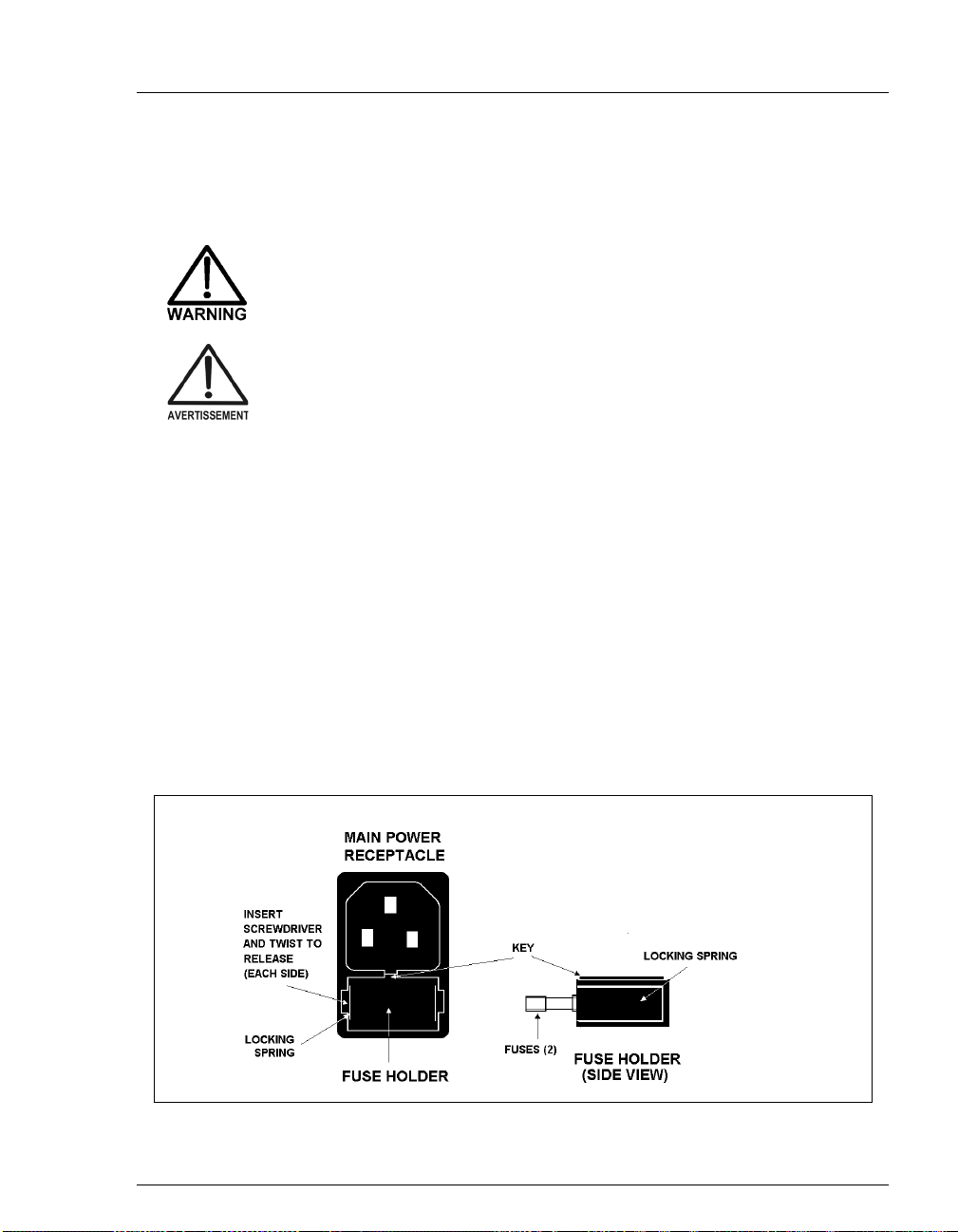
5.6 Changing Main Power Fuses
1. Turn off the main power.
HIGH VOLTAGE—Disconnect the main power cord from its
source and also from the rear panel of the GP50.
HAUTE TENSION—Débranchez le cordon d'alimentation
principal de sa source et du panneau arrière du GP50.
2. The fuse holder is part of the main power receptacle on the rear panel (see
Figure 5-8). Note the recessed lock located on each side of the fuse holder.
Using a small screwdriver, push each lock toward the center to release it.
When both locks are released and the fuse holder pops out slightly, pull the
fuse holder straight out of its compartment.
3. Replace the two fuses in the holder with new IEC127 fast-blow fuses rated
3.15 amps (P/N 054745). Dionex recommends always replacing both fuses.
5•Service
4. Reinsert the fuse holder into its compartment. The fuse holder is keyed to fit
only in its proper orientation. Apply enough pressure evenly against the
holder to engage the two locks. When both locks are engaged, the holder is
flush against the panel.
5. Reconnect the main power cord and turn on the power.
Figure 5-8. Main Power Fuse Holder
Doc. 031377-03 7/01
5-13
Page 90

GP50 Gradient Pump
5-14
Doc. 031377 -03 7/01
Page 91

A.1 Electrical
A • Specifications
Main Power
Requirements
Fuse
Requirements
A.2 Environmental
Operating
Temperature
Operating
Humidity
A.3 Physical
Dimensions
Weight
Decibel Level
100 Vac to 240 Vac, 50/60 Hz; 2.5 amps. The GP50 power
supply is main voltage auto-sensing and requires no manual
adjustment.
Two 3.15 amp fast-blow IEC127 fuses (P/N 954745)
10 °C to 50 °C (50 °F to 104 °F)
5 to 95% relative humidity (non-condensing)
33.5 cm high x 22.5 cm wide x 42 cm deep
(13.1 in x 8.9 in x 16.8 in)
6 cm (2.5 in) clearance required behind the module
19 kg (42 lb)
60 db (“A WEIGHING” setting)
A.4 Display and Keypad
Display
Keypad
Doc. 031377-03 7/01
Liquid crystal with adjustable backlighting.
26-button pad for entering commands and numeric values for
screen parameters.
A-1
Page 92

GP50 Gradient Pump
A.5 Hydraulics
Eluent
Selection
Pump
Flow Rate
Operating
Pressure
Pressure
Resolution
High Pressure
Limit
Low Pressure
Limit
Delay Volume
(No Mixer)
Four differ ent eluent componen ts; each can be pr oportioned from
0 to 100%
Dual-piston, variable speed, 100 µL (standar d bore), 25 µL
(microbore) stroke, user-selectable constant pressure or constant
flow feedback control
Standard bore pump head: 0.04 to 10.0 mL/min linearly variable
in increments of 0.01 mL/min
Microbore pump head: 0.01 to 2.50 mL/min linearly variable in
increments of 0.01 mL/min
35 MPa (5000 psi) maximum
0.07 MPa (10 psi)
0 to 35 MPa (0 to 5000 psi) in increments of 0.05 MPa (7.2 5 psi);
trips instantaneously
0. to 35 MPa (0 to 5000 psi) in increments of 0.05 MPa
(7.25 psi); trips after a time -ou t of 0.4 mL fo r the stan dard bore
GP50 or 0.1 mL for the microbore GP50
Standard bore pump head: <700 µL
Microbore pump head: <300 µL
A-2
Doc. 031377 -03 7/01
Page 93

A.6 Control
A • Specifications
Remote
Local (Front Panel)
Limited remote operation via TTL-input logic level, and TTLoutput and relay contact closures, or full remote programming
and control via the DX-LAN interface.
Methods:
The actual number of stored methods depends on available
memory. Each method may contain up to 50 separate steps.
Storage:
programs during power-down or in the event of a power failure.
Stores up to 100 separate methods (00 through 99),
Nonvolatile memory protects against the loss of
A.7 Vacuum Degas Pump Assembly (Optional)
Channels
Materials
4-channel membrane vacuum degas
Wetted materials, PEEK, PTFE
Doc. 031377-03 7/01
A-3
Page 94

GP50 Gradient Pump
A-4
Doc. 031377 -03 7/01
Page 95

B.1 Facility Requirements
Make sure the GP50 installation site meets the electrical and environmental
_
requirements in Appendix A.
Install the GP50 on a sturdy workbench at a height that ensures convenient
_
viewing of the front panel display and access to the interior.
Lift the GP50 only from the bottom or side surfaces of the
module. Lifting by the front doors will dama ge the door hinges.
Use caution when lifting the module, which weighs 19 kg
(42 lb).
Ne soulevez le GP50 que par le fond ou les côtés. Son
soulèvement par la porte du panneau avant endommagera les
charnières de la porte. Soyez prudent lorsque vous soulevez le
GP50: il pèse 19 kg (42 lb).
Allow at least 6 cm (2.5 in) free space behind the GP50 for connections and
_
ventilation.
B • Installation
The GP50 Gradient Pump is capable of operation with or without head
_
pressure on the eluent . If pre ssurization is used, provide a source of helium to
pressurize the eluent and regenerant reservoirs (if used).
House eluents at least 3 cm (8 in) above the pump i n an EO1 Eluent Org anizer
_
(P/N 044125) or in built-in eluent containment (such as the LC25
Chromatography Oven reservoir container).
Always filter eluents to remove small particulates that may contaminate the
_
pump. Install an end-line filter (P/N 045987) on the end of each eluent
reservoir line. Filters are supplied in the pressurizable reservoir Ship Kits.
Refer to the
Dionex strongly recommends degassing eluents. If the vacuum degas
_
assembly is not installed, re fer to Section 3.1.1 for manual degassing
instructions.
Doc. 031377-03 7/01
Pressurizable Reservoir Installation Instructions
for details.
B-1
Page 96

GP50 Gradient Pump
B.2 Installation Instructions
The GP50 Ship Kit contains items necessary for completing the installation.
GP50 Gradient Pump Version Ship Kit
Standard bore/microbore with PEEK components P/N 054621
Standard bore/microbore with stainless steel components P/N 054627
B.2.1 Power Connection
SHOCK HAZARD—To avoid electrical shock, a grounded
receptacle must be used. Do not operate or connect to AC
power mains without an earthed ground connection.
DANGER D'ÉLECTROCUTION - Pour éviter toute électrocution,
il faut utiliser une prise de courant avec prise de terre. Ne
l'utilisez pas et ne le branchez pas au secteur C.A. sans utiliser
de branchement mis à la terre.
The power supply cord is used as the main disconnect device.
Make sure the socket-outlet is located near the GP50 and is
easily accessible.
Le cordon d'alimentation principal est utilisé comme dispositif
principal de débranchement. Veillez à ce que la prise de base
soit située/installée près du module et facilement accessible.
Operation at AC input levels outside of the specified operating
voltage range may damage the GP50.
B-2
Doc. 031377 -03 7/01
Page 97

B • Installation
The GP50 power supply is auto-sensing, so no adjustment is required to
select the line voltage. There are two ways to control power to the GP50.
Control from the GP50
_
To implement:
Connect a modular power cord (IEC 320 C13) from
the GP50 main power receptacle (see Figure B-1) to a grounded,
single-phase power source. Use the GP50 power switch to turn the
pump power on and off.
Control from the LC30 Chromatography Oven
_
To implement:
Locate one of the IEC jumper cables (P/N 960748)
provided in the LC30 Ship Kit. Connect the jumper cable from the
GP50 main power receptacle to an IEC auxiliary receptacle on the
LC30 rear panel. Leave the GP50 power switch on continuously and
use the LC30 main power switch to turn the pump power on and off.
Doc. 031377-03 7/01
Figure B-1. GP50 Rear Panel
B-3
Page 98

GP50 Gradient Pump
B.2.2 Electronics Chassis Connections
The electronics chassis connections vary, depending on which
chromatography module is installed with the pump. Refer to the
appropriate section below.
LC10 or LC20 Connections
1. Route the leak sensor cable from the rear of the LC10
Chromatography Organizer or the LC20 Chromatography Enclosure
through the GP50 upper chase (see Figure B-1). Connect the cable to
the
LC LEAK
Figure B-2).
2. Route the solenoid valve cable from the rear of the LC10 or LC20
through the GP50 upper chase. Connect the cable to the
connector in slot 1 of the pump electronics chassis (see Figure B-2).
NOTE Refer to Appendix D for TTL and relay installation
instructions.
connector in slot 1 of the pump electronics chassis (see
LC AIR
Connect the leak
sensor cable from
the LC10 or LC20
here
Connect the serial
interface cable from
the LC30 here
Connect the
solenoid valve cable
from the LC10,
LC20, LC25, or LC30
here
B-4
PWR SPY
L
C
L
E
A
K
GP50/IP25-DSP130W
MOTOR
L
C
C
O
M
M
DIST
P6
L
C
A
I
R
SLOT 2SLOT 1
BLANK
D
I
S
T
1
3
P
I
N
P7
D
I
S
T
1
2
P
I
N
P8
SLOT 3
Figure B-2. GP50 Electronics Chassis
(Located behind pump upper door)
BLANK
SLOT 4
LAN-000K
RLY-1
OUT
RLY-2
OUT
+
TTL-1
-
OUT
+
TTL-2
-
OUT
+
TTL-1
-
IN
+
TTL-2
-
IN
+
TTL-3
-
IN
+
TTL-4
-
IN
POWER SUPPLY
GREEN - OK
RED - FAULT
Doc. 031377 -03 7/01
SLOT 5
CPU/RLY
F
R
O
N
T
P
A
N
E
L
Page 99

B • Installation
LC25 Connections
Route the electronics injection valve cable from the rear of the LC25
Chromatography Oven through the GP50 upper chase(see Figure B-1).
Connect the cable to the
electronics chassis (see Figure B-2).
connector in slot 1 of the pump
LC AIR
NOTE Do not connect the LC25 to the
in slot 1; the oven contains internal leak control
electronics.
LC30 Connections
LC LEAK
connector
1. Route the RJ-11 serial cable from the rear of the LC30
Chromatography Oven through the GP50 upper chase (see
Figure B-1). Connect the cable to the
LC COMM
connector in slot 1 of
the pump electronics chassis (see Figure B-2).
2. Route the solenoid valve cable from the rear of the LC30 through the
GP50 upper chase. Conne ct the c able to t he
connector in slot 1
LC AIR
(see Figure B-2).
NOTE Do not connect the LC30 to the
in slot 1; the oven contains internal leak control
electronics.
LC LEAK
connector
Doc. 031377-03 7/01
B-5
Page 100

GP50 Gradient Pump
B.2.3 DX-LAN Interface: 10BASE-T Connections (Optional)
NOTE Check the DX-LAN connector on the GP50 rear
panel. If a 10BASE-T RJ-45 (telephone-style)
connector is installed, follow the instructions in
Section B.2.3. However, if a BNC connector is
installed, follow the instructions in Section B.2.4.
In order to communicate with a host computer running Dionex
chromatography software, the GP50 must contain a pump interface card
(P/N 056800) and an unshielded twisted-pair 10BASE-T DX-LAN cable
(P/N 960281) must be connected from the 10BASE- T RJ-45 connector on
the rear panel to a “combo” 10BASE-T Ethernet hub (P/N 056909).
Installing or Replacing the Pump Interface Card
NOTE If the DX-LAN option was not installed at the
factory, order the pump interface card kit
(P/N 057005). The kit includes all the components
required for DX-LAN communication.
B-6
STATIC— The GP50 electronics cannot be serviced by the user.
The pump interface card must be installed by qualified
personnel. Standard anti-static procedures must be observed
when installing the interface card or handling the CPU card.
To prevent damage to the GP50, turn off the main power before
installing the pump interface card. After confirming that the
LED on the CPU card is off (not green or red), unplug the
power. Do not rely on the front panel power switch.
Pour éviter d'endommager le GP50, coupez l'alimentation
électrique principale avant d'installer la carte interface du
pompe. Après avoir confirmé que la DEL de la carte d'unité
central est étein te (ni ver te ni rouge), débranchez le courant.
Ne vous fiez pas à la position de l'interrupteur d'alimentation
du panneau avant.
Doc. 031377 -03 7/01
 Loading...