

Page 1

GP40 GRADIENT PUMP
OPERATOR’S MANUAL
© Dionex Corporation 1995
Document No. 034856
Revision 03
May 1995
Page 2

©1995 by Dionex Corporation
All rights reserved worldwide.
Printed i n the Uni ted State s of Ameri ca.
This publication is protected by federal copyright law. No part of this publication
may be copied or distributed, transmitted, transcribed, stored in a retrieval system,
or transmitted into any human or computer language, in any form or by any means,
electron ic, mecha nical, m agnetic, m anual, or othe rwise, or discl osed t o third
parties without the express written permi ssion of Dionex Corporation, 1228 Ti tan
Way, Sunnyvale, California 94088-3603 U.S.A.
DISCLAIM ER OF WARRANTY AND LIMITE D WARRANTY
THIS PUBLICATION IS PROVIDED “AS IS” WITHOUT WARRANTY OF
ANY KIND. DIONEX CORPORATION DOES NOT WARRANT,
GUARANTE E, OR MAKE ANY EXPRESS OR IMPLIED
REPRESENTATIONS REGARDI NG THE USE, OR THE RESULTS OF THE
USE, OF THIS PUBLICATION IN TERMS OF CORRECTNESS,
ACCURACY, RE LIABILITY, CURRENTNESS, OR OTHERWISE.
FURTHER, DIONEX CORPORATION RESERVES TH E RIGHT TO REVISE
THIS PUBLICATION AND TO MAKE CHANGES FROM TIME TO TIME
IN THE CONTENT HEREINOF WITHOUT OBLIGATION OF DIONEX
CORPORATION TO NOTIFY ANY PE RSON OR ORGANIZATION OF
SUCH REVISION OR CHANGES.
TRADEMARKS
DX LAN and SRS a re trademarks of Dionex Corporation.
Tefzel® is a regist ered tr ademar k of E.I . du Po nt de Ne mours & Co.
PRINTING HISTORY
Revisi on 01 , Au gust 1993
Revision 02, September 1993
Revisi on 0 3, M ay 19 95
Page 3

1 • Introduction
1.1 Ov erview . . . . . . . . . . . . . . . . . . . . . . 1-3
1.2 Ab out This Manual . . . . . . . . . . . . . . . . 1-4
1.2. 1 Typefaces . . . . . . . . . . . . . . . . . 1-5
1.2. 2 Safety Messages and Notes . . . . . . . 1-5
1.2.3 Symbols . . . . . . . . . . . . . . . . . . 1-6
1.3 Related Manual s . . . . . . . . . . . . . . . . . . 1-7
2 • Description
2.1 Front Control Panel . . . . . . . . . . . . . . . . 2-4
2.1.1 Control Panel Keypad . . . . . . . . . . 2-5
Contents
Doc. 034856 -0 3 5/95
2.1. 2 Displ a y Screens . . . . . . . . . . . . . 2-1 0
2.2 Electronics Ch assis . . . . . . . . . . . . . . . . 2-11
2.3 Mecha nica l Chas sis . . . . . . . . . . . . . . . . 2-1 4
2.4 Inter ior Components . . . . . . . . . . . . . . . . 2-14
2.4.1 Pump Eluent Manifold . . . . . . . . . . 2-15
2.4. 2 Pump Heads . . . . . . . . . . . . . . . 2-16
2.4. 3 Pump Mixer s . . . . . . . . . . . . . . . 2-17
2.4.4 Pump Pr iming Block . . . . . . . . . . . 2-17
2.4. 5 Pres sure Transducer . . . . . . . . . . . 2-17
2.5 Vacuum Degas Pump Assembly (Optional) . . . 2-18
2.6 E luent Reservoirs . . . . . . . . . . . . . . . . . 2-19
iii
Page 4

Contents
3 • Operation a nd Maintenance
2.7 Rear Panel . . . . . . . . . . . . . . . . . . . . . 2-20
2.8 Functional Descri pti on . . . . . . . . . . . . . . 2 -21
2.8. 1 Oper a t i n g M o d es . . . . . . . . . . . . . 2-23
2.8. 2 Method Control . . . . . . . . . . . . . 2-2 4
2.8.3 Eluent Delivery . . . . . . . . . . . . . . 2- 25
3.1 Getting Ready to Run . . . . . . . . . . . . . . . 3-3
3.1.1 De gas El uents . . . . . . . . . . . . . . 3-3
3.1.2 Filter E luents . . . . . . . . . . . . . . . 3-4
3.1.3 Pressurize Eluent Reservoirs . . . . . . 3-4
3.1.4 Start -Up . . . . . . . . . . . . . . . . . . 3-5
3.1.5 Selecting the Pressure Limits . . . . . . 3-5
3.2 Running Under Direct Control . . . . . . . . . . 3-6
3.3 Running Under Method Control . . . . . . . . . 3-9
3.3. 1 Creat ing a New Metho d . . . . . . . . . 3-10
3.3.2 Running a Me thod . . . . . . . . . . . . 3- 12
3.3.3 Editing a Method . . . . . . . . . . . . . 3-12
3.3.4 Delet ing a Metho d . . . . . . . . . . . . 3-14
3.3.5 Changing the Runn ing Method . . . . . 3-14
3.3.6 Controlling the Method C lock . . . . . 3-14
3.4 E x ample Method s . . . . . . . . . . . . . . . . . 3 -14
3.4.1 Isocratic M ethod Example . . . . . . . . 3-15
3.4.2 Linear Gradient Method Example . . . 3-16
3.4.3 Curved Grad ient Method Example . . . 3-22
iv
Doc. 034856 -0 3 5/95
Page 5

3.4.4 Editing a Running Method E xample . . 3-26
3.5 Routine Maint en ance . . . . . . . . . . . . . . . 3-29
3.5.1 Da ily Maint enance . . . . . . . . . . . . 3-29
3.5.2 Pe riodic Maint enance . . . . . . . . . . 3-31
3.6 Sh utd o wn . . . . . . . . . . . . . . . . . . . . . . 3-31
4 • Troubleshoot ing
4.1 Left-Right Pump Head Pressure Fluctua tions . . 4-3
4.2 Pump Will Not Start . . . . . . . . . . . . . . . . 4-6
4.3 Pu mp Stops . . . . . . . . . . . . . . . . . . . . 4-6
4.4 L iquid L e aks/Leak Alarm . . . . . . . . . . . . . 4- 9
4.5 No isy Pump Mo tor . . . . . . . . . . . . . . . . 4-11
Contents
4.6 Vacuum Degas Pump Does Not Run . . . . . . . 4-12
4.7 Vacuum Degas Pump Calibration Fails . . . . . 4-13
4.8 Inoperative Relay Control Function . . . . . . . 4-14
4.9 Poor Chromatographic Reproducibility . . . . . 4-14
5 • Service
5.1 Cleaning the Check Valve s . . . . . . . . . . . . 5 -3
5.2 P i ston S eal Replacemen t . . . . . . . . . . . . . 5-6
5.3 Pu mp Piston Repl acement . . . . . . . . . . . . 5-10
5.4 Pressu re Transducer Pad and O- Ring
Replacement . . . . . . . . . . . . . . . . . . . . 5-11
5.5 Pressure Transducer Waste Valve O-Ring
Replacement . . . . . . . . . . . . . . . . . . . . 5-13
Doc. 034856 -0 3 5/95
v
Page 6

Contents
5.6 Proportioning Valve Replacement . . . . . . . . . 5-14
5.7 Active Mixer Filter Replacement . . . . . . . . . 5-16
5.8 Changing Main Power Fuses . . . . . . . . . . . . 5-19
vi
Doc. 034856 -0 3 5/95
Page 7

A • Specifications
A.1 Electrica l . . . . . . . . . . . . . . . . . . . . . . A- 3
A.2 E nvir o n mental . . . . . . . . . . . . . . . . . . . A-3
A.3 Ph ysical . . . . . . . . . . . . . . . . . . . . . . A-3
A.4 Di splay and Keypad . . . . . . . . . . . . . . . . A- 3
A.5 Hy draulics . . . . . . . . . . . . . . . . . . . . . A-4
A.6 Gr adient Contr ol . . . . . . . . . . . . . . . . . . A-5
A.7 Vacuum Degas Pump As sembly . . . . . . . . . A-5
B • Installation
B.1 Facility Requirements . . . . . . . . . . . . . . . B-3
B. 2 Install atio n Ins tructions . . . . . . . . . . . . . . B- 4
Contents
Doc. 034856 -0 3 5/95
B. 2.1 P o wer Co nnection . . . . . . . . . . . . B-4
B.2.2 Electronic Chassis Connections . . . . . B-5
B.2.3 DX LAN Network Connec tion (Optional) B-7
B. 2.4 Waste Lines . . . . . . . . . . . . . . . . B- 9
B.2.5 Eluent Outlet Line Connection . . . . . B-10
B.2.6 E luent Inlet Line Con nectio ns . . . . . B-10
B. 2.7 P riming the Pump . . . . . . . . . . . . B- 11
B. 3 Automat ic SRS Power Co ntrol . . . . . . . . . . B- 15
B.4 Stacki n g Modules . . . . . . . . . . . . . . . . . B-17
B.5 Securing Modules (Opti o nal) . . . . . . . . . . . B-18
B.5.1 I n stalling a Shoe . . . . . . . . . . . . . B-1 8
B. 5.2 I nstalling a Tie . . . . . . . . . . . . . . B-19
vii
Page 8

Contents
C • User Interface
C.1 Operational Screens . . . . . . . . . . . . . . . . . C-5
C.1.1 Main Screen . . . . . . . . . . . . . . . . C-5
C.1.2 Detail Screen . . . . . . . . . . . . . . . . C-7
C.1.3 Method Screen . . . . . . . . . . . . . . . C-8
C.1.4 Method Extension Screen . . . . . . . . . C-10
C.1.5 Module Setup . . . . . . . . . . . . . . . . C-11
C.1.6 Pump Options . . . . . . . . . . . . . . . C-12
C.1.7 Time Function In . . . . . . . . . . . . . . C-13
C.2 Diagnostic Screens . . . . . . . . . . . . . . . . . C-14
C.2.1 Hexadecimal Entry Fields . . . . . . . . . C-14
C.2.2 Diagnostic Menu . . . . . . . . . . . . . . C-14
C.2.3 Power-Up Screen . . . . . . . . . . . . . . C-15
C.2.4 Elapsed T ime . . . . . . . . . . . . . . . . C-16
C.2.5 DSP Status . . . . . . . . . . . . . . . . . C-17
C.2.6 DX LAN Status . . . . . . . . . . . . . . C-18
C.2.7 Keyboard Test . . . . . . . . . . . . . . . C-20
C.2.8 Diagnostic Test . . . . . . . . . . . . . . . C-21
C.2.9 Pressure Statistics . . . . . . . . . . . . . C-23
C.2.10 DSP Code Version . . . . . . . . . . . . . C-24
C.3 Calibration Screens . . . . . . . . . . . . . . . . . C-25
C.3.1 Calibration Menu . . . . . . . . . . . . . C-25
C.3.2 Calibration Status . . . . . . . . . . . . . C-26
C.3.3 Leak Sensor Calibration and Status . . . C-27
C.3.4 Degas Status . . . . . . . . . . . . . . . . C-28
C.3.5 Flow Calibration . . . . . . . . . . . . . . C-29
viii
Doc. 034856 -0 3 5/95
Page 9

1 • Introduction
1.1 Overview . . . . . . . . . . . . . . . . . . . . . . . 1-3
1.2 About This Manual . . . . . . . . . . . . . . . . . 1-4
1.2.1 Typefaces . . . . . . . . . . . . . . . . . . 1-5
1.2.2 Safety Messages and Notes . . . . . . . . 1-5
1.2.3 Symbols . . . . . . . . . . . . . . . . . . . 1-6
1.3 Related Manuals . . . . . . . . . . . . . . . . . . . 1-7
Doc. 034856 -0 3 5/95
1-1
Page 10

GP40 Gr adi ent Pu mp
1-2
Doc. 034856 -0 3 5/95
Page 11

1 • Introduction
1.1 Overview
The GP40 Gradient Pump is an integral part of a DX 500
chromatography syste m. It is a microp rocessor-based, dual-pis ton,
variable-speed, gradient de livery system designed to blend and pump
mixtures of up to four different mobile phas es at precisely controlled
flow rates. The pump can deliver the selected mobile phase
composition isocratically, or as a multistep linear or curved gradient.
A Digital Signal Proce ssor (DSP) provides high speed control of
pump flow and press ure.
The GP40 can op erate as a stand -alone produc t or with other Dionex
modules as part of a complete chromatography syste m. It can also
be used with non-Dionex mod ules that meet interface requirements
for so ftwar e, TT L, or r elay contr ol.
The GP40 can be controlled locally, using the front panel keypad
and display, or from a remote host computer with a Dionex
DX LAN interface installed and PeakNet software installed on the
host computer. Limited remote control is also available from any
device capable of providing compatible TTL signals to control the
pump.
The pump’s two basic modes o f control, Direct co ntrol and Metho d
control, enable it to operate with or without reference to time-based
even ts.
The GP40 is available in four versions. An optional vacuum degas
pump is available for all versions :
GP40 Gradient Pump Version With Degas Pump Without Degas
Standar d bore wi th PEEK co mponent s P/N 0441 17 P/N 04416 5
Standar d bore wi th stai nless st eel compo nents P/N 044081 P/N 044 085
Microb ore with PEEK comp onents P/N 0440 86 P/N 044 082
Microb ore with stainles s steel com ponent s P/N 0440 83 P/N 04408 7
Doc. 034856 -0 3 5/95
1-3
Page 12

GP40 Gr adi ent Pu mp
1.2 About This Manual
This manual describes the installation, operation, and maintenance
of the GP40 Gradient Pump.
Chapter 1, Introduction, introduces the product and conventions
used in the manual, and provides safety information.
Chapter 2, Descri ption, is a descri ption of the phys ical aspec ts of the
pump, followed by a des cription of the operating featur es.
Chapter 3, Operation and Maintenance, discusses th e operating
features and meth ods, and pres ents several examples of how to run
methods. Routine preventive maintenance requirements are included
in this chapter.
Chapter 4, Troubleshooting, lists p ossible causes of prob lems and
provides step-by-step procedures to isolate an d eliminate their sources.
Chapter 5, Service, presents step-by-step instructions for service and
parts replacem ent routines.
1-4
Appendix A, Specifications , contai ns the GP40 s pecifications and
installation site specifications.
Appendix B, Installation, des cribes the installation steps necessary
to place the GP40 Gradient Pu mp into operation.
Appendix C, User Inte rface, illustrates and describes a ll front panel
menus and screens .
Appendix D, Pump Head Replacement, explains how to ch ange the
pump heads from 100 µL standard bor e to 25 µL microbore, or vice
vers a.
Appendix E, Relay and TTL Control, describes the relay and T TL
input and outpu t functions and provides setup examples.
Doc. 034856 -0 3 5/95
Page 13
1.2 .1 Typefaces
Typefaces are used in this manual as follows:
•
Capitalized bold type indicates a front pan el button:
1 • Introduction
Press
•
Upper-case bold type indic ates the name of a screen, the
to begin running the metho d.
Enter
name of a m enu, or an on- screen entry:
Go to the
Move the cursor to the
METHOD
screen.
EDIT
1.2. 2 Safety Messages and Notes
This instrument is designed to comply with the requirements
for safety set forth in I EC 1010, Safety Requirements for
Electrical Equipmen t for Measurement, Control, and
Laboratory Use.
This manual contains warnings and precautionary statem ents
that can prevent personal injury and/or damage to th e
instrument when properly followed. Safety mess ages appear
in bold typ e and are acco mpanied by icons.
Indicates a potential ha zard which could result in serious
injury or loss of life. Any hazard of this type will be located
behind a barrier and will be accessible only by use of a
tool. Access may be required during installation,
maintenance, or service.
field .
Doc. 034856 -0 3 5/95
Indicates a pot ent ial haza rd to th e oper ator, or damage to
the instrument or other property.
Indicates that the function or process of the instrument
may be impaired. Oper ation does not constitute a hazard.
1-5
Page 14

GP40 Gr adi ent Pu mp
Informational messages also appear throughout this manual.
These are labeled NOTE and are in bold ty pe:
NOTES call attention to certain information. They alert
you to an unexpected result of an action, suggest how to
optimize t he performan ce of the instrum ent, e tc.
1.2.3 Symbols
The symbols below appear on the pump, or on pump lab els.
NOTE
~
Alternating current
Protective conductor terminal
Power supply is on
Power supply is off
1-6
Doc. 034856 -0 3 5/95
Page 15

1.3 Related Manuals
During installation and operation of the GP40, you may need to
refer to one or mo re of the following manuals ( depending on your
system) for information about other modules and components
included in a DX 500 sys tem.
The following m anuals are included wit h their resp ective modules or
components:
1 • Introduction
• AS3500 Autosampler Editor Manual
• AS40 Automated Sampler Operator’s Manual
(Document No. 03 4913)
(Document
No. 034970)
• CD20 Conductivity Detect or Operator’s Manual
(Document
No. 034854)
• ED40 Electrochemical Detector Operator’s Manual
(Document
No. 034855)
• E01 Eluent Organizer Installation Instructions
(Document
No. 034582)
• Pressurizable Reservoir Installation Instructions
(Document
No. 034851)
• LC10 Chromatography Organizer Operator’s Manual
No. 034858)
• LC20 Chromatography Enclosure Operator’s Manual
No. 034859)
•
LC30 Chromatography Oven Operator’s Manual
(Document
No. 034860 )
(Document
(Document
The following manual is included in the GP40 Ship Kit:
• Installation of Dionex Fe rrule Fittings
Doc. 034856 -0 3 5/95
(Document No. 034213)
1-7
Page 16

GP40 Gr adi ent Pu mp
1-8
Doc. 034856 -0 3 5/95
Page 17

2 • Description
2.1 Front Control Panel . . . . . . . . . . . . . . . . . 2-4
2.1.1 Control Panel Keypad . . . . . . . . . . . 2-5
2.1.2 Display Screens . . . . . . . . . . . . . . 2-10
2.2 Electronics Chassis . . . . . . . . . . . . . . . . . 2-11
LC Leak . . . . . . . . . . . . . . . . . 2-12
LC30 Communication . . . . . . . . . 2-12
LC Air Valves . . . . . . . . . . . . . . 2-13
TTL/Relay . . . . . . . . . . . . . . . . 2-13
CPU . . . . . . . . . . . . . . . . . . . 2-13
2.3 Mechanical Chassis . . . . . . . . . . . . . . . . . 2-14
2.4 Interior Components . . . . . . . . . . . . . . . . 2-14
2.4.1 Pump Eluent Manifold . . . . . . . . . . 2-15
2.4.2 Pump Heads . . . . . . . . . . . . . . . . 2-16
2.4.3 Pump Mixers . . . . . . . . . . . . . . . . 2-17
2.5 Vacuum Degas Pump Assembly (Optional) . . . . 2-18
2.6 Eluent Reservoirs . . . . . . . . . . . . . . . . . . 2-19
2.7 Rear Panel . . . . . . . . . . . . . . . . . . . . . . 2-20
2.8 Functional Description . . . . . . . . . . . . . . . 2-21
Doc. 034856 -0 4 10/95
2.4.4 Pump Priming Block . . . . . . . . . . . 2-17
2.4.5 Pressure Transducer . . . . . . . . . . . . 2-17
2.8.1 Operating Modes . . . . . . . . . . . . . . 2-23
Local Mode . . . . . . . . . . . . . . . 2-23
Remote Mode . . . . . . . . . . . . . . 2-23
2.8.2 Method Control . . . . . . . . . . . . . . 2-24
2.8.3 Eluent Delivery . . . . . . . . . . . . . . 2-25
Isocratic Eluent Run . . . . . . . . . . 2-25
Gradient Eluent Run . . . . . . . . . . 2-25
2-1
Page 18

GP40 Gr adi ent Pu mp
2-2
Doc. 034 856-04 10/95
Page 19
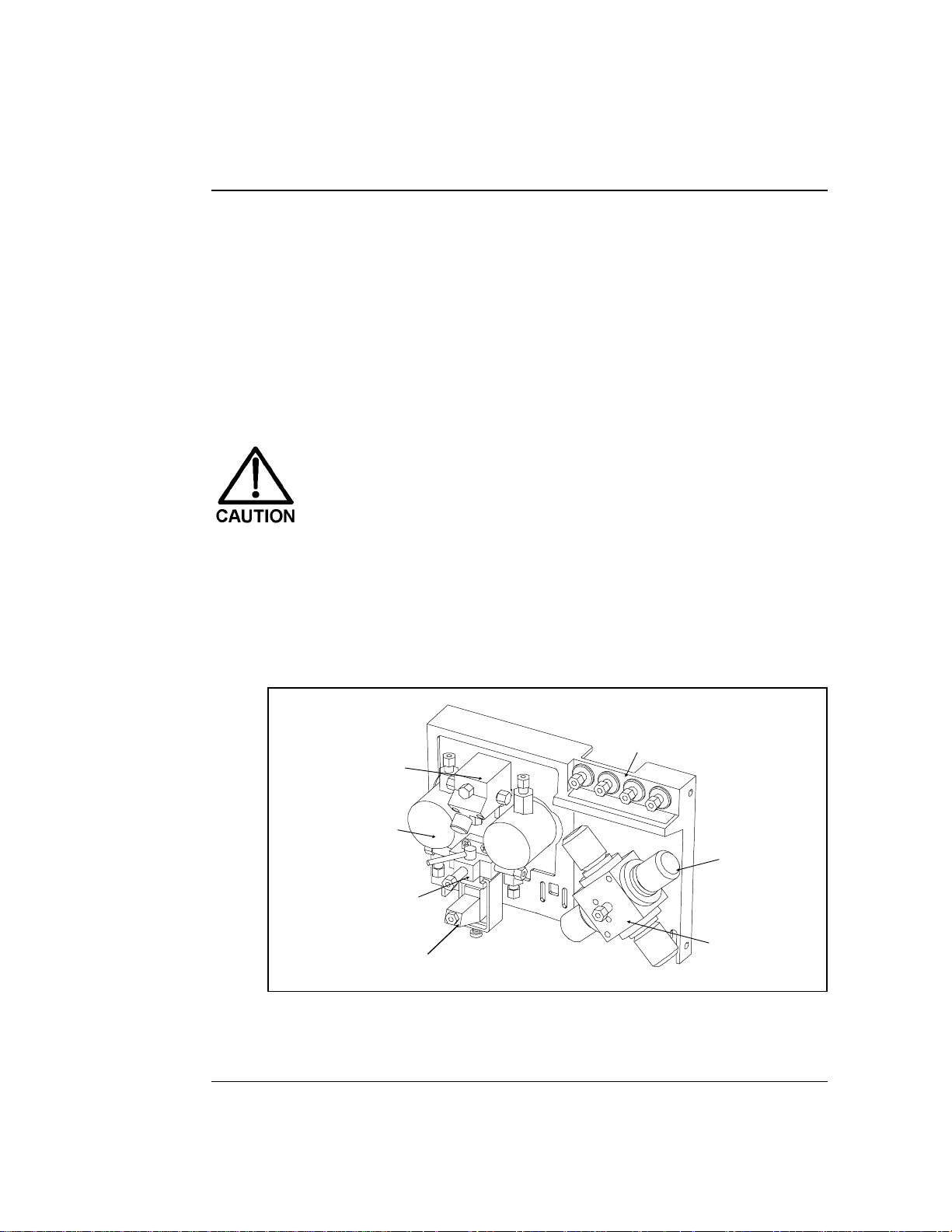
2 • Description
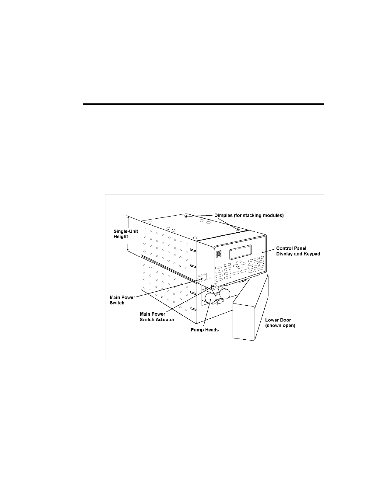
The GP40 Gradient Pump co nsists of two single-unit DX 500
encl o su re s (s ee Figure 2-1). The up per unit hous es the electronic
components, an d the lower unit ho uses the pump heads and other
mechanical pump as semblies.
The GP40 is de signed to have other single- or dual-unit modules
stacked on top of it, to a max imum of four units. See Section B.4
for the recommended s tacking configuration for DX 500 systems .
Doc. 034856 -0 4 10/95
Figure 2-1. GP40 Enclosure
2-3
Page 20

GP40 Gr adi ent Pu mp
2.1 Front Control Panel
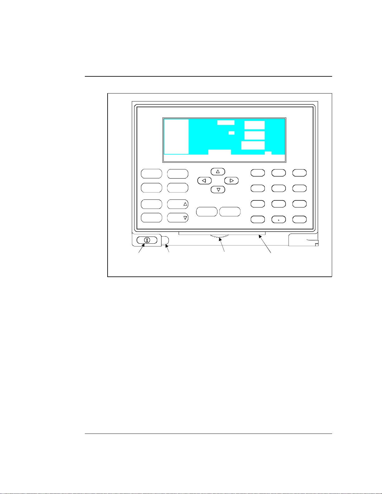
The control pa nel on the upper door of the GP40 enclosure cont ains
the liquid crystal display (LCD), the membrane keypad, and the
actuator for the main power switch (see Figu re 2-2). The doo r opens
to provide acce ss to the el ectronics cha ssis, describe d in Section 2.2.
Screen Contras t
Information is displayed on the LCD, also called the
screen
. To
adjust the screen contrast, u se the knurled kno b in the recess below
the keypad (see Figure 2- 2).
Tilt Panel
To maximize visibility, the front control panel can be tilted to four
different positions. To tilt the panel, support the door at the left side
(to prevent it from opening) and lift firmly on the tab in the middle
of the recess below the keypad (see Figure 2- 2). Push on th e tab to
return the panel to its vertical position.
Power Switc hes
The main power switch is on the bulkhead beh ind the upper door
(see Figure 2-1). An actuator for the main power switch is on the
outside of the front door, at the lower left cor ner (see Figure 2-2) .
The actuator f unctions on ly when the d oor is fully closed.
When the door is open, press th e main power switch o n the
bulkhead, instead of the actuator, to turn the module off and on.
To prevent damage to the pump circuitry and components,
always wait at least 15 seconds after powering down before
turning on the power again.
2-4
Doc. 034 856-04 10/95
Page 21
GP40 Gradient Pump
100.0 %A
0.0 %B
0.0 %C
0.0 %D
Help Message
INJECT
COLUMN A
LOCAL
2.00
PSI
mL/MIN
MIN
1000
10.25
METHOD 05
2 • Description
Off/On
Prime
Insert Select
Delete
Main Power
Switch Actuator
Hold/Run
Reset
Help Menu
Select
Tab
(for opening
the door)
Figure 2-2. GP40 Display and Keypad Layout
2. 1 . 1 Control Panel Keyp ad
The keypad is used to directly control pump operation, as
well as to create and modify programme d series of timed
events, called
•
Press
methods
Menu
to display a list of available screens.
. In summary:
Knob
(for adjusting
the contrast)
7
45
1
0
8
23
Tab
(for tilting
the panel)
9
6
Enter
•
•
Doc. 034856 -0 4 10/95
In the screens, only the fields shown in r everse video can
be edited. Oth er fields display informatio n only.
To edit a field, use the four dire ctional arrow buttons to
position the cu rsor in the reverse vid eo fields. Use the
numerical buttons to enter variable values. Use the
Select
∆
and
Select
buttons to choose between
∇
2-5
Page 22

GP40 Gr adi ent Pu mp
predetermi ned options . Pressin g a
Select
button increas es
(or decreas es) a numerica l value by one, w hile holding
down a
Select
button increa ses (or decreases) a numerical
value continuously.
•
To execute the selected value, press
Enter
, or press an
arrow button to move the cursor to the next field and
automatically enter the value.
A high-pitched be ep sounds whe n you press a button. When
an error occurs, this beep is lower in frequency. The beeps
can be disabled from the
MODULE SET-UP
screen ( see
Section C.1.6).
Off/On
Turns the pump motor off and on.
In Direct control (see Section 2.8), turnin g on the motor
causes it to pump isocratic ally using the displayed e luent
percentages a nd flow rate.
In Method control (see Section 2 .8.2), turning on the motor
causes it to pu mp at the eluent per centages and flow ra te for
the elapsed time of th e selected method, o r at the initial
conditions (when the method clock is a t
INIT
).
2-6
Prime
This button is used when priming the pump heads.
Prime
causes the pump to run at maximum volume (2.5 mL/min,
microbore; 10.0 mL/min standard bore). If the pump motor is
off when you press
Prime
, the pump automatically turns on.
To exit priming and return to the normal flow rate, press
Prime
again or press
Off/On
to turn the pump moto r off. See
Section B.2.7 for detailed priming instructions.
Doc. 034 856-04 10/95
Page 23

2 • Description
Insert
Inserts a new timed step into a method. This button functions
only when the cursor is in a
METHOD
extension s creen.
TIME
field in the
METHOD
or
1. Move th e cursor to the
TIME
field and press
Insert
. The
new step is added after the cursor positio n. Parameter
values in the new s tep are blank.
2. Fill in the time value and press
Enter
or a cursor arrow
button. If you move the cu rsor to a di fferent field before
entering the time value, the inserted step will be
incomplete and will disappear. You can insert timed steps
in any order. After you press
Enter
, they will be
automatically organized in correct chron ological order.
Delete
Removes the value from the current entry field, allowing
entry of a new value. To restore the previous value, move the
cursor from the field before entering the new value.
In th e
METHOD
screen, pressing
Delete
when the cursor is in a
step ent ry field “blank s” the step p arameter value. When the
cursor is moved from the field, the field remains blank (the
previous value is not restor ed as in other s creens). Blank step
fields indicate there is no change from the previous step.
To us e
1. Position the cursor in the method’s time field and press
2. Press
Doc. 034856 -0 4 10/95
Delete
Delete
to delete the step, press any button exce pt
to delete an entire method step:
. The time is removed and the help line dis plays:
TO DELETE THIS STEP, PRESS DELETE AGAIN
Delete
again to delete the step. If you do not want
Delete
or the
decimal point and the origin al time and step parameters
are then resto red.
2-7
Page 24

GP40 Gr adi ent Pu mp
Hold/Run
Turns the method clock off (
Hold
) and on (
Run
). This button
functions only when the pump is under Method control (see
Section 2.8.2).
When the method clock is in Hold, pressing
Hold/Run
, starts
the clock. The clock s tarts either at the initial step of a new
method, or if resuming an interrupted method, at the time at
which the clock was put in Hold.
When the m ethod clock is in Run, pr essing
Hold/Run
, stops
the clock, thereby “holding” the method and freezing the
current conditions.
Reset
Changes the method clock time to
INIT
and causes the initial
conditions specified by the method to occur. This button
functions only when the pump is in Method control.
If the method is running, it continues running. If the method
is on hold, the metho d clock executes the initial conditions
and holds.
2-8
Select
and
∆
Select
∇
When the cursor is positioned a t a field that has
predetermined parameters, these buttons cycle through the
choices. In fields which have predeter mined numeric values,
Select
∆ increases the value by one unit and
decreases the value by one un it. Holding down the
Select
∇
Select
button increa ses (or decreases) the value cont inuously. Press
Enter
or a cursor ar row button to execute the new value.
,
, and
→
←, ↑
↓
The four cursor directional buttons move the cursor, in the
direction of the arrow, to the next entry field. If there is no
Doc. 034 856-04 10/95
Page 25

2 • Description
changeable field in that directio n, the curs or moves
diagonally or remains where it is.
After entering or selecting a new value in an entry field,
pressing an arrow button to move to another field als o saves
and/or executes the change. This performs the same function
as pressing
Enter
followed by an arrow.
In a few fields the cur sor arrow does not perform the enter
function. You must pres s
Enter
after entering or selecting
values in the following fields:
•
DIA GNOSTIC TEST
•
SA VE T O
•
Calibration screen fields
•
Menu fields
Help
and
screen fields
RUN
fields on the
METHOD
screen
Displays a help screen specific to the current entr y field.
Displays one o f three menus, dep ending on the current screen:
•
•
•
Doc. 034856 -0 4 10/95
Menu
From any operational s creen, pressing
MENU of SCREENS
.
From any diagnostic screen, pressing
DIAGNOSTIC MENU.
MENU of SCREENS
Pressing
.
Menu
again returns you to the
From any calibration scre en, pressing
CALIBRATION MENU
DIAGNOSTIC MENU
the
. Pressing
and then to the
Menu
Menu
displays the
Menu
displays the
Menu
displays the
again returns yo u to
MENU of SCREENS.
See Figure C-1 for the GP40 scree ns and menu s tructure.
2-9
Page 26

GP40 Gr adi ent Pu mp
Numeric Buttons
Enters numeric values into the current entry field. The
numeric buttons are 0 through 9 and th e decimal.
Enter
Saves and/or executes changes made in entry fields. After
pressing
the same field. It does not automa tically move to the next
entry field. In menu screens, press ing
highlighted screen.
Enter
, the cursor moves back to the left margin of
Enter
opens the
In th e
METHOD
screen, pressing
copy only. To save the editing change s to a permanent
method, move the cursor to the
method number, and press
2.1.2 Display Screens
When the pump has successfully powered-up and passe d all
diagnostic tests, the
Figure 2-3 ) and after a few se conds, th e
(see Figure 2-5) . If one of the d iagnostic tests fails at
power-up, the
MAIN
screen. See Section C.2.8 if this occurs.
Help Message
DIAGNOSTIC TEST
GP40 GRADIENT PUMP
Enter
saves entries to an edit
Enter
POWER-UP
SAVE T O
.
screen displays briefly (see
field, enter the
MAIN
screen displays
screen displays instead of the
PUMP HEAD VOLUME 100 uL
MODULEWARE REV n.nn
BIOS REV n.nn
2-10
Figure 2-3. Power- Up Screen
Doc. 034 856-04 10/95
Page 27

2 • Description
100.0 %A
0.0 %B
LOAD
COLUMN A
2000
2.00
PSI
mL/MIN
0.0 %C
10.27
0.0 %D
Help Message
POWER-UP
The
DIAGNOSTIC MENU
later time.
MAIN
The
screen displays status information in enlarged
characters to make viewing easier from a distance. From the
MAIN
screen you can set p ump operating parameters such as
the percentage of eluents to run, th e flow rate, or the method
number to run.
To access the remaining GP4 0 screens, press the
to display the
menu, you can sele ct individual operational scr eens, or the
DIAGNOSTIC MENU
number and press
screen name and press
description of ea ch GP40 screen.
screen can also be op ened from the
MENU of SCREENS
LOCAL 2
Figure 2-5. Main Screen
METHOD
, if you wish to view the information at a
(see Figure 2-4). From the
screen. To open a screen, en ter the screen
Enter
, or move the cursor to the desired
Enter
. See Appendix C for a
MIN
Menu
button
Doc. 034856 -0 4 10/95
MAIN SCREEN
1
DETAIL SCREEN
2
METHOD
3
DEGAS OPTIONS
4
Help Message
Figure 2-4. Menu of Screens
MENU of SCREENS
MODULE SET-UP
5
PUMP OPTIONS
6
TIME FUNCTION IN
7
DIAGNOSTIC MENU
8
2-11
Page 28
GP40 Gr adi ent Pu mp
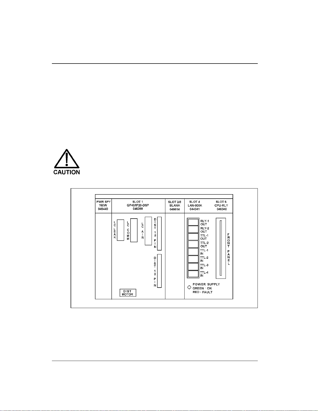
2.2 Electronics Chassis
The electronics c hassis is locate d behind the upper door of the GP4 0
enclosure . The chas sis include s several electro nic cards (pr inted
circuit boards) that are used to contr ol the GP40. Connec tors on the
cards also allow communic ation between the GP4 0 and other
DX 500 modules. Figure 2-6 shows the e lectronics components with
the upper door op en. To open the door, pull on the tab loca ted to the
right of the main power actuator (see Figure 2-2) .
Do not remove any of the electronics cards fro m the pump.
There are no user-serviceable components on t he cards.
If serv icing i s requir ed, it must be p erformed by qual ified
personnel and appropriate electrostatic discharge (ESD)
handling proc edures must be followed .
2-12
Figure 2-6. Electronics Chassis
(Located behind pump upper door)
Doc. 034 856-04 10/95
Page 29

2 • Description
LC Leak
The leak control cable from the LC20 C hromatography
Enclosure or the LC10 Chromato graphy Organizer connects
to the
LC LEAK
connector in slot 1.
When a leak occurs in the LC10 o r LC20, it is reported to the
GP40. The LC30 Chromatography Oven does not connect to
the GP40
LC LEAK
connector; it has its own internal leak
control electron ics.
LC30 Communication
The LC30 Chr omatography Oven’s RJ-11 serial cable
connects to the
LC COMM
connector in sl ot 1. When
connected, the L C30 can be remotely co ntrolled by the
PeakNet workstation.
LC Air Val ves
The cable from th e air solenoid valves on the LC1 0, LC20, or
LC30 connects to the
LC AIR
connector in s lot 1. When
connected, the GP40 can e lectrically act uate the s olenoid
valves which control the position of the injection valve and
the optional column switch ing valve in the LC10, LC20, and
LC30. Use the
MAIN
or
METHOD
screen to select the valve
positions. See Appen dix C for a description of the screens.
TTL/Relay
A strip of eight rela y and TTL conn ectors is located in slot 4 .
These connec tors interface with Dion ex and non-Dionex
modules for relay and TTL control of the pump. Appendix E
describes the r elay and TTL func tions and the connec tions
between the GP40 an d other modules .
CPU
Control Moduleware for the GP40 resides on the CPU/Relay
cards.
Doc. 034856 -0 4 10/95
2-13
Page 30

GP40 Gr adi ent Pu mp
The CPU log ic and Relay I/O cards occupy slo t 5 in the car d
cage. The R elay I/O card rid es piggyback on th e CPU card
and extends over the front o f slot 4. The card is short enough
to allow the optional DX LAN p ump interface card
(P/N 044195) to mou nt behind it in slot 4. A 60-p in ribbon
cable links the CPU log ic to the display and keypad. The
logic monitors the inter nal power supply outpu ts, and reports
the status on the multic olored LED at the bottom of s lot 4.
•
Green indicates normal operation.
•
Red indicates a power fault. The module will enter its
diagnostic state a nd inhibit all other controls u ntil the
fault is corrected. If this occurs, turn the power off for a
few seconds and then turn it back on. If the problem
persists, call Dionex.
2-14
Doc. 034 856-04 10/95
Page 31
2.3 Mechanical Chassis
The mechanic al chassis is housed in a pull-out drawer located
behind the lower door of the GP40 en closure. The front of the
chassis cont ains the interior compon ents described in Section 2.4.
Other mechan ical assemb lies are lo cated insi de the chas sis drawer.
For routine op eration, the drawer must be pu shed in and the drawer
lock, located on the lower right corner of the chassis, tight ened. The
drawer is pulled out only for service procedures.
Observe the warning label on the inside of the lower doo r.
The arrows on the label indicate moving mechanical par ts
that present pinch hazards when the pump i s on and the
mechanical drawer is open. Do not o perate the p ump wi th
the mechanical chassis drawer pulled out.
2.4 Interior Components
2 • Description
Figure 2-7 shows the interior compon ents located behind the lower
door.
Bulkhead
Pressure
Transducer
Pump Heads
Priming Block
Active Mixer
(standard bore
pumps only)
Figure 2-7. Interior Components
Fittings
Proportioning
Valves
Eluent Manifold
Doc. 034856 -0 4 10/95
2-15
Page 32

p
p
(
y)
(
y)
GP40 Gr adi ent Pu mp
To Column
Mixer
microbore onl
Pressure
Transducer
Pum
Heads
Priming Block
Mixer
standard bore onl
Figure 2-8. Eluent Flow Sc hematic
2. 4. 1 Pump Elue nt Manifol d
Front panel bulkhead fittings A through D are connected to
the chemically-inert proportioning soleno id valves that
control eluent selection. The proportioning valves gener ate
the gradient mixture by cycling ope n and closed to deliver the
desired percent age of each selected eluent t o the manifol d.
The output from the four proportionin g valves is combined in
the manifold. Figure 2-8 shows the eluent flow path through
the components.
Eluent
A In
A
Eluent
Eluent
B In
C In
B C D
D
C
A
B
Eluent
D In
Bulkhead
Fittings
Manifold and
Pro
ortioning
Valves
2-16
Doc. 034 856-04 10/95
Page 33

2.4.2 Pump Heads
There are two GP40 pump head co nfigurations: standard bore
and microbore. T he table below summarizes the features of
each type and the operating co nditions for each configuration.
2 • Description
Pump
Head Ty pe
Standard
Bore
Microbore
*Flow rates are a djusta ble in increm ents of 0 .01 mL /min.
Piston
Volume
100 µL
25 µL
Although t here is some over lap in flow rat es between the
two pum p ve rsions, continuous ope r ation of the micr ob ore
pump heads at flow rates above 2.0 mL/min will decrease
seal and pump life. For the best extended operation at
2.0 mL/min or above, repl ace the mic robore pump heads
with standard bore pump heads. Similarly, whe n running
gradients, the standard bore pump heads should not be
used below 0.4 mL/min.
Pump
Operation
Isocratic 0.04 – 10.0 4-mm and
Grad ient 0.4 – 10. 0 4-mm and
Isocratic and
Gradient
NOTE
Flow R ate
(mL/min)*
0.01 – 2.5 0 1-mm –
Instructions for replacing the pump h ead assembly are
shipped wit h the replaceme nt head and in cluded in
Appendix D of th is manual. Contact y our Dionex office to
order the conversion pump head kits. Refer to Appendix D
for kit part numbers.
Column
Sizes
9-mm I D
9-mm I D
4-mm I D
Maximum
Operating
Pressure
35 MPa
(5000 psi)
35 MPa
(5000 psi)
35 MPa
(5000 psi)
See Figures 5-1 and 5-2 for an illus tration of the pump heads
and interconnecting lines.
Doc. 034856 -0 4 10/95
2-17
Page 34

GP40 Gr adi ent Pu mp
2.4.3 Pump Mixers
A pump mixer ensures complete mixing of the proportioned
eluents prior to injection. Two types of mixers are available:
•
In standard bore GP40 pumps (10 0 µL piston volume), a
Dionex active mixer (P/N 04898 8) is installed betw een the
eluent manifold and the priming block. The active mixer
contains an electromagnetic stir bar to mix the
proportioned elu ents.
•
In microbore GP40 pumps (25 µL piston volume), a
GM-4 gradien t mixer (P/N 049135) is in stalled between
the pump outlet an d the injection valve.
2. 4. 4 Pump Pr iming Block
The priming block “tee” directs the flow of eluent from the
manifold into the pump he ads. The priming block is also used
for ra pid r emoval o f air f rom th e syst em.
2-18
Refer to Section B.2.7 for instructions on priming the pump
heads.
2.4 .5 Pressure Transducer
From the priming block, the liqu id stream is directed to the
inlet check valves on the pump heads, through the pump
heads, and finally through th e outlet check valves to the
pressure transducer.
Flow from the outlet check valves on the pump heads is
combined in the pres sure trans ducer. The press ure transd ucer
measures the system press ure at this point . The interactive
constant-flow/constant-press ure control program on the DSP
precisely controls the pump moto r speed to assure flow rate
accuracy. A Kel-F disk an d PTFE O-ring isolate the eluent from
the metal pressure transducer.
The press ure transd ucer include s a press ure waste valve for
use during priming of the pump . Open this valve for a few
Doc. 034 856-04 10/95
Page 35

2 • Description
seconds to relieve the pres sure and force air out of the
system, then cl ose it to resume analysis (see Figur e B-5).
Flow output from th e pressure tr ansducer is directed out o f
the pump module to the rest of the chromatography system
(injection valve, column, detector). On microbore pumps,
flow passes through the GM-4 mixer be fore entering the
injection valve.
See Section B.2.5 in A ppendix B for outlet line connections .
Refer also to the manual for the module being us ed for
specific int erconnect info rmation.
2.5 Vacuum Degas Pump Assembly (Optional)
The Dionex vacuum degas pu mp (P/N 047263) provides continuous
on-line vacuum degassin g of one to four eluents (see Fig ure 2-9). If
ordered, the assembly is installed in the pump at the factory. This
assembly consists of:
•
A 4-channel degas cha mber (with degas membrane s) with 17 mL
internal capacity per chan nel
•
A dual-stage d iaphragm vacuum pump
•
A solenoid valve
•
An on-board vacuum sensor
•
The electronics required to operate the vacuum pump
•
Fittings, tubing, and other accessories
Doc. 034856 -0 4 10/95
2-19
Page 36

GP40 Gr adi ent Pu mp
Figure 2-9. Vacuum Degas Component Schematic
By default, at power-up, the degas pump turns on for 2 minutes.
Thereafter, the pump turns on for 30 sec onds at 10-minute inte rvals.
You can check the vacuum chamber pressure from the
screen (s ee Section C. 3.4). The
change the cycle time and duration (see Section C.1.5).
DEGAS OPTIONS
DEGAS STATUS
screen allows you to
All components of the vacuum degas assembly are made of inert
materials or corrosion-resistant materials. However, Dionex
recommends that you thoroughly flush any chemicals out of the
tubing with deionized water after each use to avoid crystallization in
the membrane pores.
2.6 Eluent Reservoirs
Dionex strongly reco mmends degassing all eluents and st oring them
in reservoirs pressurized with helium. This help s prevent bubbles
(resulting from eluent outgassing) from forming in the eluent
proportioning valves, pu mp heads, and the detector cell. D egassed
eluents and pressurized reservoirs a re especially imp ortant when
combining aqueo us and non-aqueo us component s (e.g., water and
methanol). Pressur izable reservoirs allow eluents to be stored under
2-20
Doc. 034 856-04 10/95
Page 37

2 • Description
a specific atmosphere. The following reservoirs are available from
Dionex:
•
1-liter glass reservoirs with shatterproof plastic coating
(P/N 044126)
•
2-liter glass reservoirs with shatterproof plastic coating
(P/N 044127)
•
1-liter plastic reservoirs (P/N 044128)
•
2-liter plastic reservoirs (P/N 044129)
Do not use the 2-liter plastic reservoir (P/N 044129) for
off-line vacuum degassing of eluents. The reservoir was
not designed for this purpose.
Refer to the
Pressurizable Reserv oir Installation Instructions
(Document No. 0345 81) for installation d etails.
Two optional E01 Eluent Organizers (P/N 044125) fit on top of the
system encl osure. Each organizer can accommodate up to two
reservoirs with the volume listed below. Contact your Dionex office
for ordering information.
No. of
Reservoirs
2
2
1
Description
1 Liter glas s or plas tic
2 Liter plastic
2 Liter glas s
Total Volume
in Liters
2 L
4 L
2 L
2.7 Rear Panel
The rear p anel contains t he main power rece ptacle with fuses, a nd a
BNC connector for interfacing the GP40 with the PeakNet
workstation through the DX LAN. The r ear panel is illustrated in
Figure B-1 in Appendix B.
Doc. 034856 -0 4 10/95
2-21
Page 38

GP40 Gr adi ent Pu mp
2.8 Functional Description
There are t hree ways to op erate the GP4 0 pump:
•
In Local mode, y ou use the fron t control panel buttons an d
screens to set operating parameters. See Section 2.8.1 f or a
description of Local mode.
•
In Remote mode, you us e PeakNet to send operating commands
from th e host compu ter via the D X LAN. See S ection 2.8 .1 for a
description of Remote mode.
•
With TTL input, a controlling device, such as an integrator or
another DX 5 00 module, sends TTL si gnals to the pump. T he
TTL input signals can be used to turn the pump motor off and
on, set the method clo ck to hold or run, or incremen t and
decrement the meth od number. All other GP40 operating
parameters must be set locally with th e control panel. See
Appendix E for a description of TTL control.
To select the ope rating mode:
1. Open either the
displays either
2. To chang e the mode, move the cursor to this field; press
Select
or
cursor arrow button. (For TTL input control, set the GP40 to
Local mode. )
∇
MAIN
LOCAL
to toggle to the d esired mode and press
100.0 %A
0.0 %B
DETAIL
or
REMOTE
or
COLUMN A
screen. The o perating m ode field
(see Figur e 2-10)
LOAD
2000
2.00
.
Enter
PSI
mL/MIN
0.0 %C
MIN
0.0 %D
Help Message
Figure 2-10. Main Screen
10.27
LOCAL 2
METHOD
Select
or a
∆
2-22
Doc. 034 856-04 10/95
Page 39

2 • Description
In addition to the operatin g modes, two pump cont rol modes are
availab le:
•
In Direct control, commands are executed immediately when
entered. Because there is no time-based program, the method
clock is not u sed and
•
In Method con trol, comman ds are executed accor ding to the
Hold/Run
and
Reset
do not operate.
timed steps in a pro grammed method. See Section 2.8.2 for
details about M ethod control.
To select the con trol mode:
1. Open either the
displays either
MAIN
DIRECT CN TRL
2. To chang e the mode, move the cursor to this field; press
Select
or
to toggle to the d esired mode and press
∇
or
DETAIL
or
screen. The c ontrol mode field
METHOD
(see Figure 2-10).
Select
Enter
or a
cursor arrow button.
NOTE
If the GP 40 is connected to a host c omp ut er, PeakNet commands
can also be used to change the operating and control modes.
Both Direct and Method control are available in either the Local
mode or the Remote mode. T he combination of available operating
modes and control modes provides flexibility in the way the pump
can be oper ated. The tab le below summarizes the different oper ating
and control mode configurations:
Operating/Control Mode Pump Oper ation
Local/Direct
Local/ Met hod
Commands entered from the control panel and
executed imme diately af ter bein g enter ed
Commands entered from the control panel and
executed by r unning a p rogram med meth od
∆
Remote/Direct
Remote/Method
Doc. 034856 -0 4 10/95
Commands sen t from PeakN et and execu ted
immediately wh en received
Commands sen t from PeakN et and execu ted by
running a programmed method
2-23
Page 40

GP40 Gr adi ent Pu mp
2.8.1 Operating Modes
Local Mode
When the pump is powered up, it is in Local mode (see
Figure 2-1 0). In Local mode, the pu mp accepts o perating
commands from two sources:
•
Direct input from th e front panel keypad
•
TTL inputs from a remote controller, such as an integrator
or another DX 500 module
Remote Mode
In Remote mode, the pump acc epts operating commands from
the host comp uter, which are se nt via the DX LAN using
PeakNet software.
Remote control can be set to either n ormal Remote or Locked
Remote:
2-24
•
In normal Remote mode, all front pane l buttons function
except
Hold/Run
. Operating parameters can be ch anged,
providing they do not interfere with a method while it is
running in remote contro l.
•
In the Locked R emote mode, al l operating chan ges from
the GP40 front panel ar e disabled. Lo cked Remote mo de
can be sel ected only fr om the host computer. It can be
cleared eit her from the co mputer or by p owering the
GP40 down. The GP40 always powers up in the L ocal
mode.
If the pump is running a method when you c hange to the
Remote mode, the computer will n ot interrupt the method
unless you s end an abort command from the compu ter.
Doc. 034 856-04 10/95
Page 41

2.8.2 Method Control
In Method con trol, comman ds are executed accor ding to the
time-based steps programmed in a method. Each step
specifies the eluent co mposition and flow rate to be delivered
by the pump at a given time. The s elected eluent mixture is
delivered either isocratically, or as a mu ltistep linear or
curved gradient. As the method runs, the GP40 calculates the
changes in eluent composition req uired to deliver a gradient
from one method step to the next or to match the selected
curve.
2 • Description
Methods are programme d, saved, and edited from the
METHOD
screen (see Figure 2-11). See Section 3.3 for programming
instructions.
METHOD EDIT
TIME %A
INIT
25.0
0.00
123.45
345.67 v
Help Message
100.0
10.0
17.2
%B %C %D V
25.0
0.0
22.2
19.6
Figure 2-11. Method Screen
SAVE TO RUN 100605
LIMITs 0 - 5000
C FLOW
25.0
0.0
32.3
33.2
25.0
0.0
35.5
30.0
0
5
L 1.00
I
L
2.00
PSI
>
>
>
>
The following summarizes basic information about using
methods.
•
The pump can run under method con trol while you are
entering or editin g any method, even the one th at is
currently running.
•
When saving changes to the currently ru nning method, or
switching to a different method, the method clock
continues runnin g unaffected. Only tho se parameter
changes which affect the method after the c urrent time
will be implemented in the current run.
Doc. 034856 -0 4 10/95
2-25
Page 42

GP40 Gr adi ent Pu mp
•
The GP40 can s tore up to 100 separate methods
(0 through 99) in memory. The actual number is
memory-dependen t, i.e, depends on the size of e ach
method and the amount of available memory. Typica lly,
less than 1 00 can be stored.
•
Methods are retaine d in memory even after the pump is
powered-down.
•
Each method can have a maximum of 50 time-based steps.
Eac h method step specifies a time, an eluent co mposition, a
gradient curve number, an injection valve position (Load or
Inject), and a flow rate . Step 1 always star ts at
condition). Step 2 always starts at
•
After PeakNet downloads a method to the GP40 , the
computer sends a command to activate the method number
and execute the
running when the compu ter activates the new method, the
old method is in terrupted and the method clock is r eset to
INIT
conditions.
TIME = 0.0
INIT
conditions step. If a method is
INIT
.
(initial
2-26
2.8 .3 Eluent Delivery
Isocrati c Eluent R un
The simplest use of the GP40 Gradient Pump is for the
delivery of an isocratic (uncha nging) mixture of one or more
eluents. If more than one eluen t is selected, the pump delivers
a proportional mixtur e of the eluents b ased on the percentage
of each eluent s elected. The combined percent ages of all
eluents selected must tota l 100% or the pump will no t run.
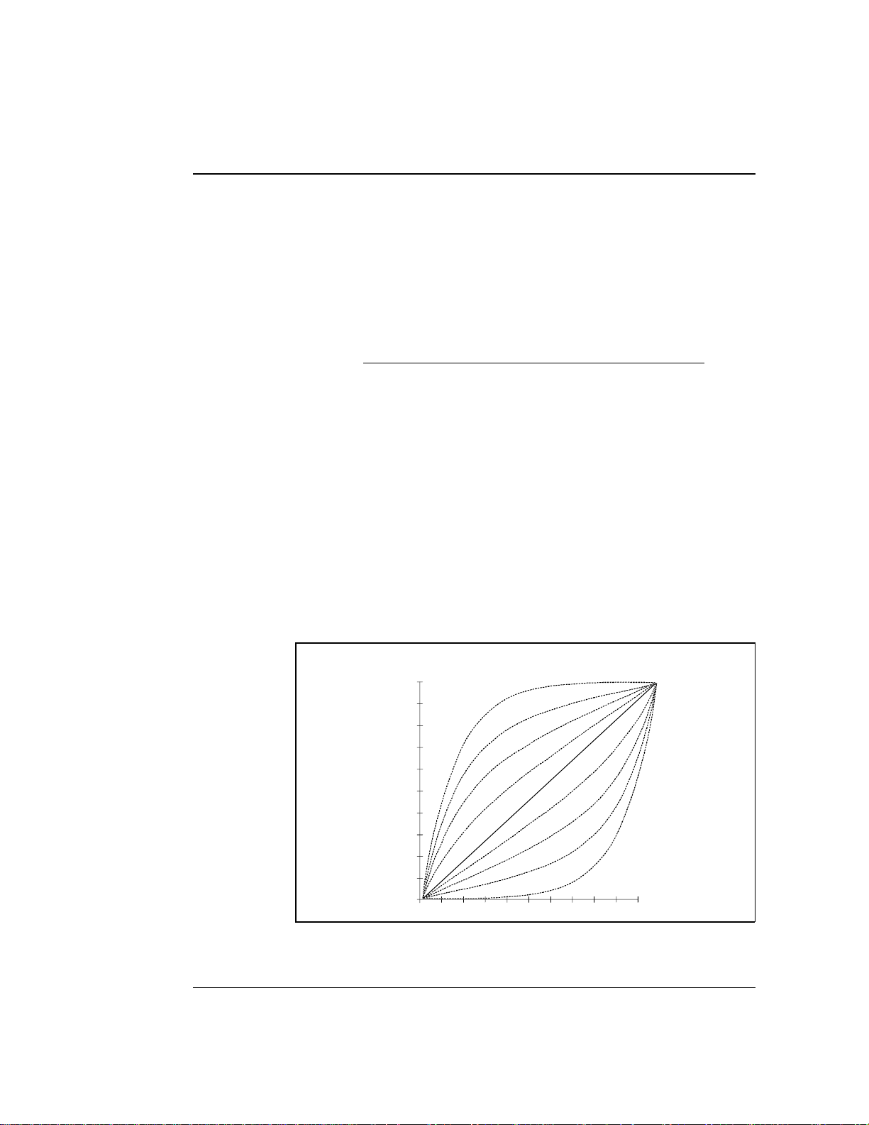
Gradient El uent Run
The pump ca n produce ste p, linear, concave, or convex curves
in eluent concentration over a specified time period. The
slope of the gradient is determine d by the selected gradient
curve (see Figure 2-12) and the time between th e starting and
Doc. 034 856-04 10/95
Page 43
2 • Description
ending points of a gradient s tep. It is important to note the
following points:
•
The curve number parameter determines whether the
pump delivers a linear or curved gr adient.
Curve numbers are defined as follows:
Curve No. Gradient Type
1, 2, 3, 4 Convex
5 Linear ( powe r-up defa ult )
6, 7, 8, 9 Concave
•
Convex curves cause rapid changes in eluent composition
at the beginni ng of the curve an d slower changes at the
end. Concave cur ves cause slower changes at the
beginning and rapid changes at th e end.
•
Slope changes over time become more extreme as curves
go from 6 to 9 (more concave) and from 4 to 1 (more
convex). Figure 2-12 shows the eluent co mposition
profiles correspond ing to curves 1 thro ugh 9, normalized
for 0-100% for 10 minutes.
Doc. 034856 -0 4 10/95
1.0
.9
.8
.7
.6
.5
.4
.3
.2
.1
0
0
1
2
3
4
5
6
7
8
9
1
2
45678910
3
Figure 2-12. Eluent Compositi on Profile for Curves 1-9
2-27
Page 44

GP40 Gr adi ent Pu mp
A curve numb er in a step inst ructs the pump to use
the selected curve number when moving from the
previous step to that step. Because there are no
previous ste ps for
camnot be e ntered for thes e steps .
•
The gradient slop e does not change during a step if curve
5 (the d efault setting) is selected, b ecause cur ve 5
represen ts a linear gr adient.
•
Any consecutive method steps specifying identic al eluent
compositions will ge nerate an isocratic segment,
regardless of the curve number selected.
•
A step gradien t change is a steep linea r change from o ne
eluent to another. A step change occurs automatically if
the following three conditions occur: the time interval
between two steps is less than 0.1 minute; at the
beginning of the step, one eluent is at 0%; and at the en d
of the step , none of the eluents is at 0%.
INIT
NOTE
or
TIME = 0 .0
, curve numbers
2-28
Doc. 034 856-04 10/95
Page 45

3 • Operation and Maintenance
3.1 Getting Ready to Run . . . . . . . . . . . . . . . . 3-3
3.1.1 Degas Eluents . . . . . . . . . . . . . . . 3-3
Degassing Eluents Manually . . . . . . 3-3
3.1.2 Filter Eluents . . . . . . . . . . . . . . . . 3-4
3.1.3 Pressurize Eluent Reservoirs . . . . . . . 3-4
3.1.4 Start-Up . . . . . . . . . . . . . . . . . . . 3-5
3.1.5 Selecting the Pressure Limits . . . . . . . 3-5
3.2 Running Under Direct Control . . . . . . . . . . . 3-6
3.3 Running Under Method Control . . . . . . . . . . 3-9
3.3.1 Creating a New Method . . . . . . . . . . 3-10
3.3.2 Running a Method . . . . . . . . . . . . . 3-12
3.3.3 Editing a Method . . . . . . . . . . . . . . 3-12
3.3.4 Deleting a Method . . . . . . . . . . . . . 3-14
3.3.5 Changing the Running Method . . . . . . 3-14
Doc. 034856 -0 3 5/95
3.3.6 Controlling the Method Clock . . . . . . 3-14
3.4 Example Methods . . . . . . . . . . . . . . . . . . 3-14
3.4.1 Isocratic Method E xample . . . . . . . . 3-15
3.4.2 Linear Gradient Method Example . . . . 3-16
3.4.3 Curved Gradient Method Example . . . . 3-22
3.4.4 Editing a Running Method Exa mple . . . 3-26
3.5 Routine Maintenance . . . . . . . . . . . . . . . . 3-29
3.5.1 Daily Maintenance . . . . . . . . . . . . . 3-29
3.5.2 Periodic Maintenance . . . . . . . . . . . 3-31
3.6 Shutdown . . . . . . . . . . . . . . . . . . . . . . . 3-31
3-1
Page 46

GP40 Gr adi ent Pu mp
3-2
Doc. 034856 -0 3 5/95
Page 47

3 • Operation and Maintenance
3.1 Getting Ready to Run
3.1.1 Degas Eluents
Dionex strongly reco mmends degassing all eluents and
storing them in reservoirs pressurized with filtered inert gas
(see Section 3.1.3) . This helps prevent bubbles (resulting
from eluent outgassing) from forming in the eluent
proportioning valves, pump he ads, and the detector cell.
Degassed elue nts and press urized rese rvoirs are espe cially
important when comb ining aqueous an d non-aqueous
components (e.g., water and methanol).
The GP40 with the option al vacuum degas pump assembly
provides continuou s on-line vacuum degassin g of eluents and
reagents (four maximum).
If the GP40 is not equ ipped with the vacuum degas assembly,
manually vacuum-degas eluents daily, as described below,
and store them in pressurized reservoirs.
Doc. 034856 -0 3 5/95
Degassing Eluents Manually
1. Prep are the eluent requ ired for your application . Pour it
into a vacuu m flask and atta ch the flask to a vacuum
pump or water aspirator.
2. Vacuum degas the eluen t for 5 minutes by shaking or
sonication.
3. R emove the flask from the vacuum. Do not allow water
to flow from the aspirator back into the flask.
4. Po ur the degassed elue nt into a pressuriza ble reservoir. Be
careful not to shake the eluent.
3-3
Page 48

GP40 Gr adi ent Pu mp
5. Install end-line filters and pressurize the reservoirs (see
Sections 3.1 .2 and 3.1.3).
3.1.2 Filter Eluents
Always filter eluents before operation to remove small
particulates that may contaminate the prop ortioning valves or
the pump c heck valves and cau se erratic fl ow rates or loss of
prime. End-line filters (P/N 045987) are su pplied in the
pressurizable rese rvoir ship kits for this pur pose.
Install an end-line filter on the end of each eluent line inside
the reservoir. To prevent air from being drawn through th e
lines, make sure that the end of th e filter reaches the bottom
of the eluent r eservoir.
3.1. 3 Pressuriz e Eluent Reservoirs
Pressurize eluent reservoirs with filtered inert gas (preferably
helium). If helium is not available, argon or nitrogen can be
used. Refer to the Pressurizable Reservoir Installation
Instructions for details.
3-4
1. Verify that a regulator (P/N 04659 4) is installed on the
gas supply line to the reservoirs.
2. Turn on the gas supply and adjus t the pressure to 55 KPa
(8 psi).
Never pressurize the reservoirs above 69 KPa (10 psi).
Doc. 034856 -0 3 5/95
Page 49

3.1.4 Start-Up
3 • Operation and Maintenance
1. Turn on the main pump power. The
displays brief ly (see Figure 2 -3) and after a f ew seconds,
MAIN
the
screen d isplays (see Fig ure 2-5). A series of
diagnostics tests is run at power-up. If one of the tests
fails, the
DIAGNOSTIC TEST
screen displays instead. See
Section C.2.8 if this o ccurs.
2. Press
Off/On
to start the pump flow.
3. C heck the pres sure readin g on the
display updates the pressure rea dout once per pisto n
stroke. The rea ding from one str oke to the next should be
within 3%.
A variation of more than 3% , indicates the pump is out of
prime. The pump can lose prime if it h as been shut down
for an extended period of time. (Overnight shutdown
generally does not cause loss of prime.) Refer to
Section B.2.7 fo r priming instructions, or see Section 4. 1
for other conditions whic h can cause the pump to lo se
prime.
3.1. 5 Selecting the Pr essure Limits
POWER-UP
MAIN
screen. The GP40
screen
Doc. 034856 -0 3 5/95
The high and low pressure limits automatically stop the pump
in the event of a system malfunction (e.g., overpressurizing
because of a bloc kage, or low pressur e caused by a lea k
downstream from the pump).
When running un der Direct control, enter the pressur e limits
from t he
DETAIL
screen (see Figu re 3-1).
When running un der Method contr ol, enter the limits from
METHOD
the
in the
scr een as a par t of e ach method. The limits are se t
INIT
step and remain unchange d throughou t the analy sis.
When a limit trip s tops the pump , the method clock immediately
stops and goe s to Hold. T he current status of the program tha t
was running at the time is displayed on the front panel.
3-5
Page 50

GP40 Gr adi ent Pu mp
To select the limits:
1. Go to the
LIMIT
field.
DETAIL
or
METHOD
screen and move the cursor t o the
2. Enter a low pressure limit that is 1.4 to 2 MPa (200-300 psi)
below the norm al system o perating pres sure, as ind icated by the
pressure display on the front panel. The low pressure limit is
activated after 13 pump pist on strokes, i.e. , after 1.3 mL
(standard) or 0 .325 mL (microbore) of fluid is pumped throu gh.
3. Enter a hi gh pressure limit that is 2 to 2.75 MPa (300-40 0 psi)
above the normal system oper ating pressu re. The pump is
equipped with a pressure limiter that prevents operation above
35 MPa (5076 psi) .
DETAIL SCREEN
100.0 %A
0.0 %B
0.0 %C
0.0 %D
LOCAL
Help Message
2125
2.00
INJECT
COLUMN
LIMIT
DIRECT CNTRL
PSI
mL/MIN
SAMPLE
A
1200-1900 PSI
TTL1
TTL2
RLY1
RLY200
1
1
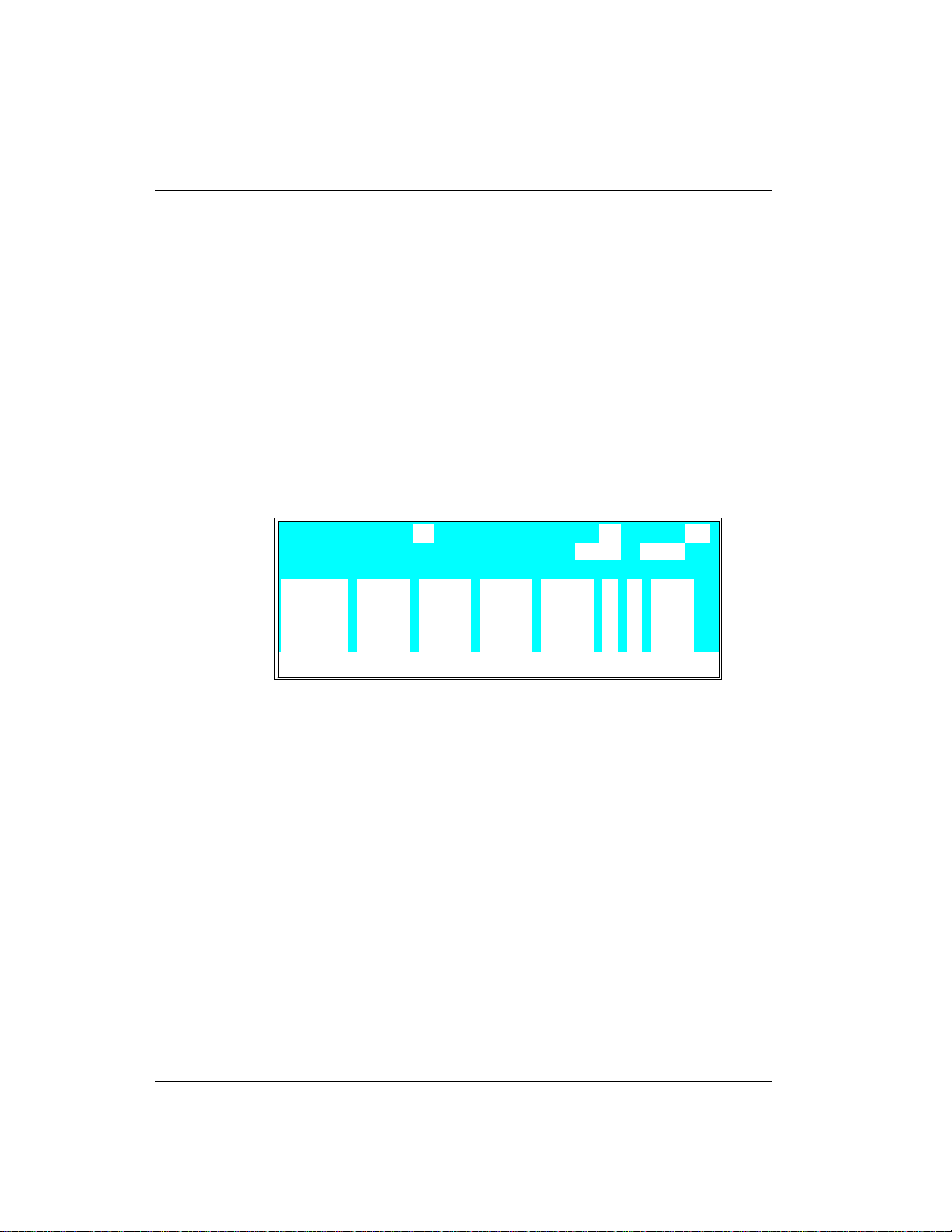
Figure 3-1. Detail Screen: Setting Pressure Limits
3.2 Running Under Direct Control
Direct control is most often used for s imple runs, such as the
delivery of an isocratic (uncha nging) mixture of one or more eluents.
Direct Control Example:
Specify an isocratic mix ture of 60% eluent A, 25% eluent B , and
15% eluent C to be pumped at 2.0 mL/min. Figure 3-2 illustrates th e
isocratic profile for this example. Figure 3-3 illustrates the
screen as it will appear when the example is set up.
3-6
MAIN
Doc. 034856 -0 3 5/95
Page 51

3 • Operation and Maintenance
Figure 3-2. Isocratic Run Profile
60.0 %A
25.0 %B
LOAD
COLUMN A
2000
2.00
PSI
mL/MIN
15.0 %C
0.0 %D
Help Message
Figure 3-3. Main Screen: Running Under Direct Control
1. Go to the
MAIN
or
DETAIL
LOCAL
screen.
2. Check that the operating fields are set to
CNTRL
(see Figure 3-3). If
REMOTE
set, move the cursor to the appropriate field; press
Select
to toggle the value, and press
∇
button.
3. Move to the %A field and enter 60; move to the %B field and
enter 25; move to the %C field and press
automatically filled in to make the e luent percentages equal 100).
4. Move to the
mL/MIN
field and enter 2.
DIRECT CNTRL
LOCAL
Enter
METHOD
Enter
and/or
DIRECT
and
are currentl y
Select
or
∆
or a cursor arrow
(15 is
5. If the pump is cu rrently off, press
and begin the isocratic delivery.
Doc. 034856 -0 3 5/95
Off/On
to turn on the motor
3-7
Page 52

GP40 Gr adi ent Pu mp
Wait at least 10 minutes after starting the pump or changin g the flow
rate before beginning an analysis. This allows the pump’s real-time
electronic pulse damping circuitry to stabilize the flow rate.
3.3 Running Under Method Control
This section provides general instructions on how to create, edit, and
run methods. Sectio n 3.4 provides s tep-by-step examples for
creating linea r gradient and curved gradient methods, and f or
modifying an existing method.
Use the following guidelines when entering time-based parameters
in the
•
•
METHOD
screen :
When setting method times, allow at least 10 minutes after
starting the pump or changing the flow rate before beginning a n
analysis. This allows the pump ’s real-time electronic pulse
damping circuitry to stabilize the flow rate.
In th e %A, %B, %C, and %D columns, enter decimal percentage
values from 0.1% th rough 100% for the eluen t compositions. The
combined percentages for all eluents mu st total 100% or the
pump will not ru n.
3-8
•
In th e V column, select the position o f the injection valve (either
L
for load or I for inject).
•
In th e
FLOW
column, enter the pump flow rate. Flow rates are
adjustable in increments o f 0.01 mL/min. See Section 2.4 .2 for
the available flow rate ranges. They vary, depending on the size
of the pump head and whether the run is isocratic or grad ient.
Continuous operation of the micr obore pump heads at flow
rates above 2.0 mL/min will decrease seal and pump l ife.
For the best extended operation at 2.0 mL/min or above,
replace the microbore pump heads with standard bore
pump heads. Similarly, when running gradients, the
standard bore pump heads should not be used below
0.4 mL/min.
Doc. 034856 -0 3 5/95
Page 53

3 • Operation and Maintenance
•
For steps other than
INIT
and time zero, enter a curve number in
the C column. The curve number determines whe ther the pump
delivers a linear o r curved gradi ent (see Section 2.8.3). The
default is curve 5 (linear).
NOTE
A curve numb er in a st ep inst ructs the pump t o use the s electe d
curve number when moving f rom the p revious s tep to t hat st ep.
Because th ere are no previ ous steps for
numbers are not entered for these steps.
•
If a step field is blank, the value set in the previous step is used.
•
If a method contains more steps than ca n be displayed o n one
INIT
TIME = 0 .0
or
, curve
screen, they are scrolled off the screen. A small arrow down (∨)
next to the time entry at the b ottom of the screen indicates there
are additional steps below. A small arrow up (^) adjacent to the
top time entry indicates there a re additional steps above (see
Figure 3-16). Move the cursor to the bottom or top of the screen
and then move one more line to view the additional steps.
3.3. 1 Creating a New Method
Doc. 034856 -0 3 5/95
You can create a new method when th e method cl ock is in
either
Hold
1. Go to the
2. Check that the pump is set to
currently set, move the cursor to the field; press
Select
or
Run
or
∇
.
MAIN
or
DETAIL
screen .
LOCAL
to toggle the value, and press
. If
REMOTE
Enter
is
Select
or a cur sor
arrow button.
3. Go to the
4. In th e
METHOD
EDIT
field, enter the number of the method to be
screen.
created. You can enter the nu mber of an unused method or
the number of an existing meth od that you want to edit
and save as a new method . If you enter the number of an
unused method, the screen will lo ok similar to the
example screen in Figu re 3-4.
∆
3-9
Page 54

GP40 Gr adi ent Pu mp
5. In th e
LIMITs
field, set the low and high pressu re limits
(see Section 3. 1.5).
METHOD EDIT
TIME %A
100.0
0.00
Help Message
Figure 3-4. Method Screen: Creating a New Method
%B %C %D V
SAVE TO RU N 055
LIMITs 0 - 5000
C FLOW
_
L 1.00INIT
_
PSI
6. Each method starts out with two timed steps (see
Figure 3-4). The first step is an initial condition s step
INIT
with
in the
zero step w ith
TIME
column. The second step is a time
0.00
in the
TIME
column. The parameters in
each of t hese first two steps can be ch anged but the ste ps
cannot be d eleted. Enter the parameters for thes e two
steps as required for the method.
>
>
>
>
3-10
7. To enter a new step, use one of the following method s:
Move the cursor to the emp ty
•
TIME
field below the last
step and enter the elapsed time at whic h to start the
new step.
Move the cursor to a ny of the
•
Insert
. This adds a new step after the cursor position.
TIME
fields and press
Enter the elapsed time at whic h to start the new step.
After you pres s
Enter
or a cursor arrow button, timed
steps are automatic ally organized in chronolo gical order.
8. Enter the remainder of th e parameters for the new step.
Doc. 034856 -0 3 5/95
Page 55

9. After entering the time-based parameters, move the cursor
to the
SAVE T O
field. If you ar e editing an existing method,
enter a new number for the method and press
save the method to a new number. If not, press
save the current method.
3. 3 . 2 Runni ng a Meth od
3 • Operation and Maintenance
Enter
to
Enter
to
1. If the pump motor is off, pres s
Off/On
to turn the motor
on.
2. Go to the
from
LOCAL.
3. In th e
MAIN
DIRECT CN TRL
METHOD
You can also select the method numb er in the
screen. Move th e cursor to
DETAIL
or
screen and, if necessary, toggle
to
METHOD
and from
REMOTE
to
field, enter the des ired method number.
METHOD
RUN
and enter the desired
method number.
If the method clock is already runnin g when you enter the
method number, the method sta rts immediately.
If the clock is in Hold, press
Hold/Run
to start the method.
4. The elapsed time on the method clo ck when the method
begins determines where (at what step an d parameters)
the method begins run ning:
If the method clock is at
•
begins running using the
INIT
or time zero, the method
INIT
ial condition parameters.
3. 3 . 3 Editing a Method
Doc. 034856 -0 3 5/95
If the method clock is greater than zero, the method
•
begins running using the parameters spe cified in the
step for that elapsed time. Press
method at the
INIT
ial conditions.
Reset
to start the
After entering a method, you can modify it by changing,
adding, or de leting steps and par ameters. These ch anges can
3-11
Page 56

GP40 Gr adi ent Pu mp
be made when the me thod clock is s topped, or while it is
running. If the method y ou are editing is curren tly running,
the changes are stored in me mory and implemented when yo u
save the method.
After you save changes, there is no way to recall the original
method. Theref ore, if you plan to make experimental changes
to a method but want to retain the original meth od in its
unmodified form, save a copy of the or iginal to a different
number.
Use the following basic steps to e dit a method:
1. Go to the
METHOD
screen. In the
EDIT
field, enter the
number of the meth od to be modified.
2. M ake changes as ne eded:
To change a field’s value
•
, position the cursor in the
field and enter th e new value. The previous value is
automatically deleted.
To add a method step
•
TIME
fields and press
empty
TIME
field below the last step and enter the
, move the cursor to any of the
Insert
, or move the cursor to the
elapsed time at which to start the new step. After you
press
Enter
or a cursor arr ow button, the new step is
automatically moved to the correct chronological
position. Continue e ntering parameters for the new
step.
To de lete a meth od s tep
•
to be deleted and p ress
, move the cursor to the step
Delete
twice.
3. When c hanges are complete, move the cursor to the
SA VE TO
field . Pre ss
Enter
to save the changes to the
current method, or enter a new method number a nd press
Enter.
3-12
If you save changes to th e currently running me thod, they
are immediately incorporated in the run and executed at
the programmed time. If, however, a change is made to an
Doc. 034856 -0 3 5/95
Page 57

event that has already been executed, it will not be
incorporated a s part of th e current run. To run the
changed version of the method, press
method at the
INIT
3.3.4 Deleting a Method
3 • Operation and Maintenance
Reset
to restart the
ial conditions.
To delete an entire method, move the cursor on the
screen to the
INIT
step, then p ress
3. 3 .5 C hang ing t he Ru nni ng Met hod
To change from the metho d currently running to a different
method, enter the new method number in the
METHOD
screen, and press
Enter
. The new method begins
running using the p arameters specified in the step for the
current elapsed time. Press
INIT
ial conditions.
Reset
3. 3. 6 Control ling the Method Cl ock
Hold/Run
The
MAIN
the
•
To start a nd stop the method clock, press
•
To reset the clock to
•
To set the clock to a specific e lapsed time, enter the time
into the
button, the
DETAIL
and
MIN
field in the
Reset
button, and the
screens control the metho d clock:
INIT
, press
MAIN
or
method will star t (or continue) running using the method
parameters specified for that time.
METHOD
Delete
twice.
RUN
field on the
to start the method at the
MIN
fie ld s in
Reset
DETA IL
Hold/Run
.
screen. The
.
3.4 Example Methods
The examples in this s ection provide step-by-s tep instructions for
creating three types of methods: isocratic, line ar gradient, and
curved gradient. The last example demonstrate s how to edit a
running method.
Doc. 034856 -0 3 5/95
3-13
Page 58
GP40 Gr adi ent Pu mp
For all of the method examples, set the pump to Local mode,
Method control. To do this, go to the
necessary, toggle from
LOCAL.
3.4. 1 Isocratic Method Example
Specify an isocratic mix ture of 60% eluent A, 25% elu ent B,
and 15% eluent C to be p umped at 2.0 mL/min. Figure 3-2
illustrates the isocratic profile for this example.
DIRECT CN TRL
MAIN
to
DETA IL
or
METHOD
screen, and if
and from
REMOTE
to
Figure 3-5 illustrates the
METHOD
screen as it will a ppear
when the example i s set up.
METHOD EDIT
TIME %A
60.0
0.00
Help Message
Figure 3-5. Method Screen: Isocratic Run Example
1. Go to the
EDIT
the
METHOD
field (1, fo r example). The screen aut omatically
%B %C %D V
25.0 15.0
screen and enter a method number in
changes the number i n the
SAVE TO RU N 011
LIMITs 0 - 5000
SA VE T O
field to the number of
the method being e dited.
If Method 1 currently exists and you wan t to delete it,
•
move the cursor to
TIME = INIT
and press
delete the entire Method 1.
PSI
C FLOW
_
L 2.00INIT
_
Delete
twice to
>
>
>
>
3-14
If you want to retain the origina l Method 1, enter a
•
new, unused , method number in th e
EDIT
field .
Doc. 034856 -0 3 5/95
Page 59

3 • Operation and Maintenance
2. Move th e cursor to the %A field and enter 60; move to the
%B
field and enter 25; move to the %C field and pres s
Enter
(15 is automatically filled in to make the eluent
percentages equal 100). Skip th e C (Curve) and V (Valve)
fields. Move to the
FLOW
field and ente r a flow rate of
2.00.
3. Move th e cursor to
SA VE TO
and press
method.
4. Move th e cursor to
this case) and press
Run
, enter the method number (1, in
Enter
to select the programmed
method. If the pump motor is off, press
pump delivering the eluent mixture.
5. If the method clock is in hold, press
method running.
3.4 .2 Linear Gradient Method Example
The following summarize s the linear grad ient method steps :
•
Create Method 2 to begin u nder isocratic conditions with
100% eluent A at 2.0 mL/min.
•
After 5 minutes, begin a dding eluent B and decreasing
eluent A until, at 10 minutes, the mixture is 65% eluent A
and 35% elue nt B.
•
Begin adding eluent C to th e mixture while con tinuing to
decrease eluent A and increase elu ent B until, at 15
minutes, the elu ent composition is 0% eluen t A, 50%
eluent B, an d 50% eluent C.
Enter
to save the
Off/On
Hold/Run
to start the
to start the
Doc. 034856 -0 3 5/95
•
Continue in creasing elue nt C and begin decr easing elue nt
B until, at 25 minute s, the eluent composition is 100%
eluent C.
•
Make a step cha nge to 100% elue nt D at 25.01 minu tes.
Pump 100% elue nt D for 4.99 min utes.
3-15
Page 60

GP40 Gr adi ent Pu mp
•
At 30.01 minutes, r eturn to 100% eluent A and
re-equilibrate your system for the next analysis.
Figure 3-6 illustrates the gradient profile for this method.
Figure 3-6. Linear Gradient Method Profile
1. Go to the
EDIT
the
If Method 2 currently exists and you wan t to delete it,
•
move the cursor to
METHOD
screen and enter a method number in
field (2 , for examp le).
TIME = INIT
and press
Delete
twice to
delete the entire Method 2.
If you want to retain the origina l Method 2, enter a
•
new, unused , method number in th e
2. Move to the
FLOW
field of t he
INIT
step and enter a f low rate
EDIT
field .
of 2.00.
Figure 3-7 illustrates the
METHOD
screen as it appears so
far. You can now begin entering th e method s teps tha t will
generate the gradie nt profile.
3-16
Doc. 034856 -0 3 5/95
Page 61

3 • Operation and Maintenance
METHOD EDIT
TIME %A
100.0
0.00
Help Message
Figure 3-7. Linear Gradient Method Example
(After Step 2)
%B %C %D V
3. Move th e cursor to the %A field of th e
press
Enter
. 100% of eluent A is automatically filled in.
4. Move the cursor to the line below
store a step at
%A
and press
TIME = 5.0
Enter
to enter 100% a nd define a step with
SAVE TO RU N 022
LIMITs 0 - 5000
C FLOW
_
L 2.00INIT
_
TIME = 0
TIME = 0,
PSI
step and
and enter 5 to
minutes. Then move the cursor to
the same eluent compo sition as the previous step.
Although there is no change in eluent parameters, th e
100% of %A mu st be entered at 5.00 minutes to estab lish
5.00 as the gradient start point.
This marks the end of the is ocratic section of the run and
the beginning of the eluent B concentratio n ramp. From
this point on, the c oncentration of eluent A decrea ses
from 100% as the concentration of elu ent B begins to
increase from 0%.
>
>
>
>
Doc. 034856 -0 3 5/95
5. Move the cursor to the next line. Enter 10 in the
TIME
field. Move the cursor to the %A field and enter 65,
followed by 35 in the %B fie ld .
After a total of 10 minutes (5 min utes of isocratic
conditions plus 5 minutes to gradua lly decrease the
amount of eluent A in the mixture while increasing the
amount of eluent B), the eluent comp osition is 65% elue nt
A and 35% elue nt B.
3-17
Page 62
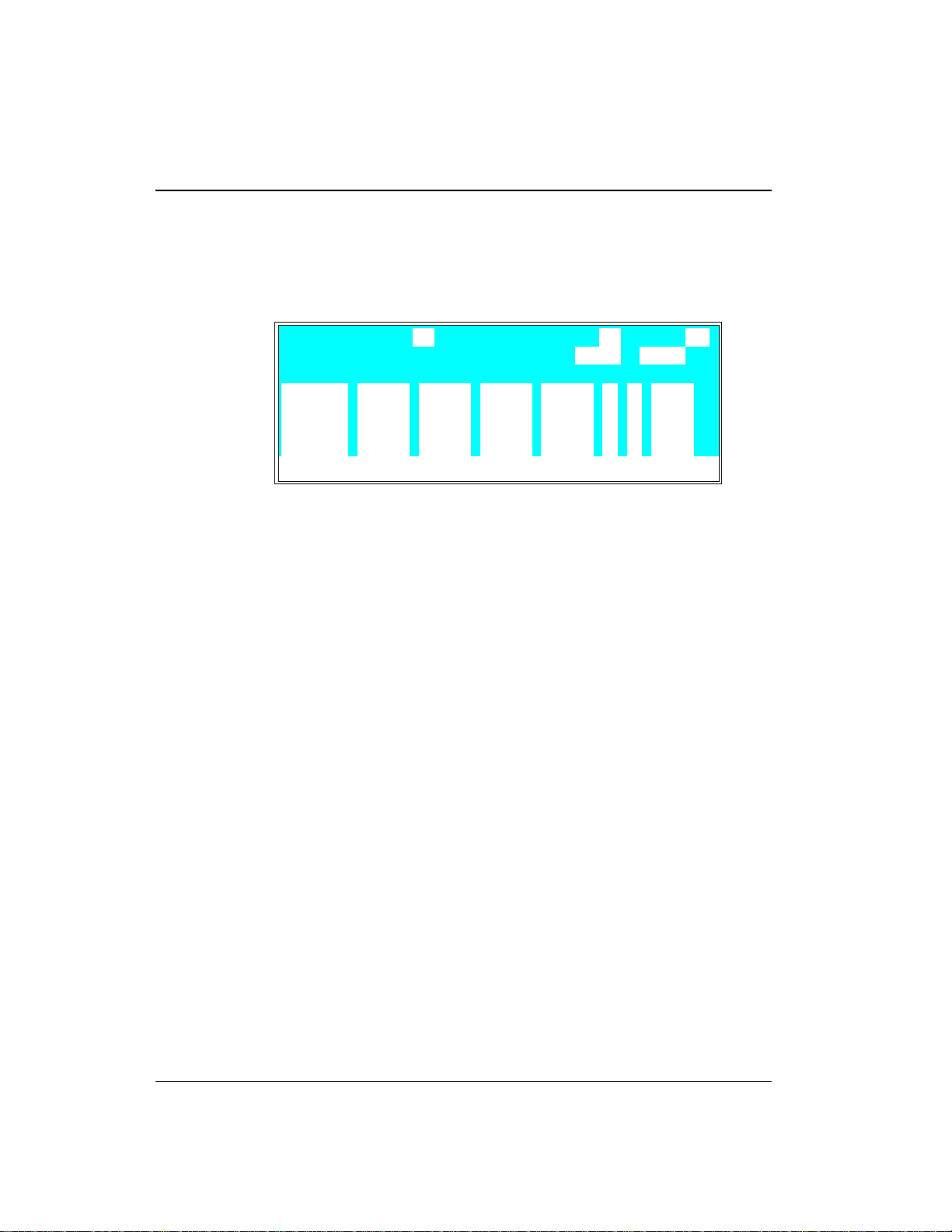
GP40 Gr adi ent Pu mp
This step mark s the end of the sec ond segment and the
beginning of the elu ent C concentration r amp. Figure 3-8
illustrates the
METHOD
screen a s it appear s after Step 5.
METHOD EDIT
TIME %A
100.0
0.00
5.00
10.00
Help Message
(After Step 5)
100.0
100.0
65.0 35.0
Figure 3-8. Linear Gradient Method Example
%B %C %D V
SAVE TO RU N 022
LIMITs 0 - 5000
C FLOW
_
L 2.00INIT
_
6. Move the cursor to the next line. Enter 15 in the
field. Move the cursor to the %B field and enter 50,
followed by 50 in the %C fie ld .
Beginning with the method s tep immediately preceding
this one (
TIME = 10
), the pump begins adding eluent C,
starting with 0%. Whe n the method reaches this s tep
(after 15 minutes ), eluent C is at 5 0%, eluent B at 50%,
and eluent A at 0%.
7. Move the cursor to the next line. Enter 25 in the
field. Move the cursor to %C and enter 100.
PSI
>
>
>
>
TIME
TIME
3-18
After a total of 25 minutes, the concentration of eluent B
drops to 0% an d the concentratio n of eluent C in creases
to 100%.
8. Move the cursor to the next line. Enter 25.01 in the
field. Move the cursor to %D and enter 100.
The concentration of eluent C drops to zero and the
concentration of e luent D, which the pump began adding
0.6 seconds (0. 01 min) earlier, reaches 100%. This is a
step change
in eluent composition to 10 0% eluent D. A
Doc. 034856 -0 3 5/95
TIME
Page 63
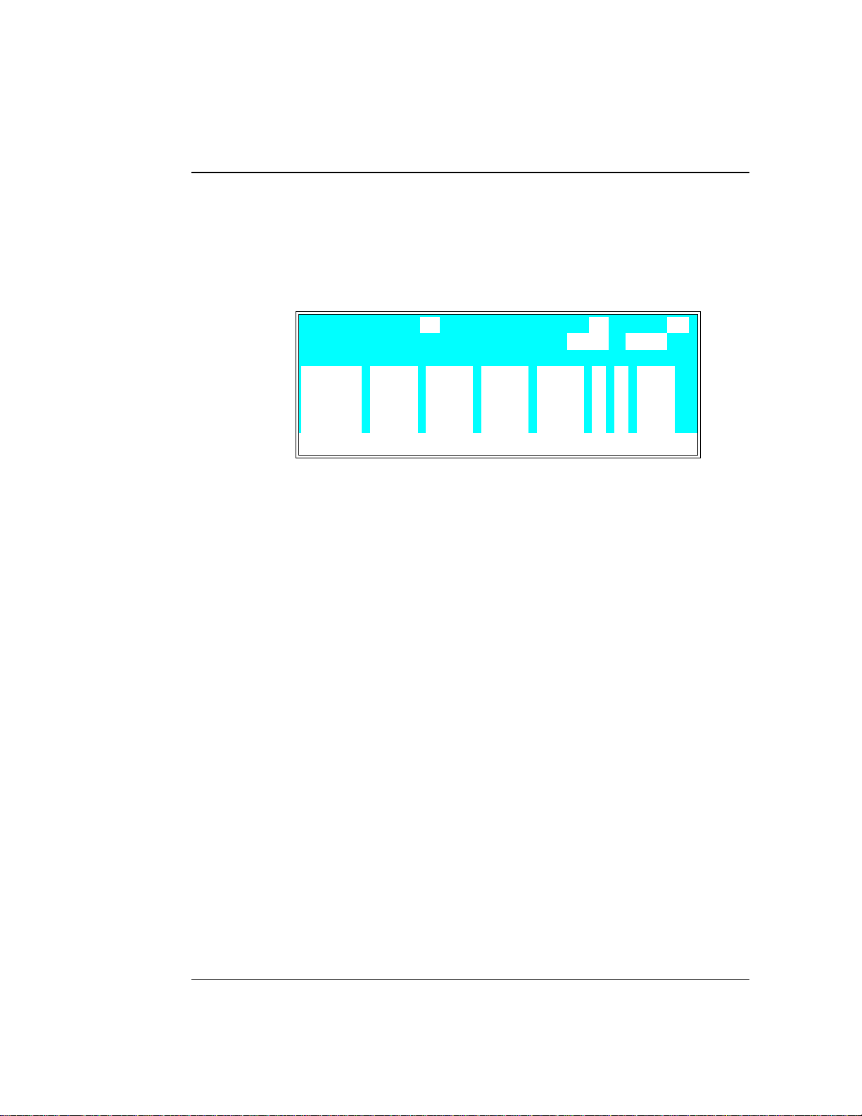
3 • Operation and Maintenance
step change is a very steep linear gradient in which the
eluent composition changes from on e eluent to another in
6 seconds. Figu re 3-9 illustrates the
METHOD
screen as it
appears af ter Step 8.
METHOD EDIT
TIME %A
10.00
15.00
25.00
25.01
Help Message
(After Step 8)
>
65.0 35.0
Figure 3-9. Linear Gradient Method Example
%B %C %D V
50.0 50.0
9. Move the cursor to the next line. Enter 30 in the
SAVE TO RU N 022
LIMITs 0 - 5000
C FLOW
100.0
100.0
2.00
PSI
>
>
>
>
TIME
field. Move the cursor to the %D field and enter 10 0. The
eluent composition remains u nchanged at 100% eluent D
for 4.99 minutes.
10. Move the curso r to the next line and enter 30. 01 in the
TIME
field. Move the cu rsor to the %A field and enter 100.
This causes an other step gradie nt from 100% D to 100%
A.
11. Move the cursor to the
SA VE TO
field and press
Enter
to
save the method to memory. Figure 3-10 illustrates the
completed method.
Doc. 034856 -0 3 5/95
3-19
Page 64

GP40 Gr adi ent Pu mp
METHOD EDIT
TIME %A
25.00
25.01
30.00
30.01
Help Message
(Complete)
12. Pres s
the
INIT
>
100.0
Figure 3-10. Linear Gradient Method Example
MENU
and
METHOD
step (if necessary).
%B %C %D V
Enter
field. Press
13. If the pump motor is off, press
14. If the metho d clock is in hold, pres s
SAVE TO RU N 022
LIMITs 0 - 5000
100.0
100.0
100.0
to go to the
Reset
MAIN
to reset the method to th e
Off/On
Hold/Run
C FLOW
2.00
screen. Enter 2 in
to start the pump.
to start the
method running . When the method rea ches the last step in
the method (
TIME = 30.01
), the pump will continue to pump
isocratically until the clock is reset.
PSI
>
>
>
>
3-20
Doc. 034856 -0 3 5/95
Page 65

3 • Operation and Maintenance
3.4. 3 Curved Gradient Method Example
When attempting to optimize the s eparation of a single
component in a complex mixture, it is often helpful to
employ paired segm ents of a cu rved gradient. For example , if
the analyte is an oligon ucleotide that elutes with
0.32 M NaCl in a linear gradient run, you can move
potentially interferin g components of the sample away from
the target oligonucleotide by first programming a segment
from 0% to 32% of a 1 M NaCl solu tion using curve 2. Then,
program a segment from 32 % to 100% of 1 M NaCl using
curve 8. The resulting gradient profile is shown in
Figure 3-11.
Doc. 034856 -0 3 5/95
Figure 3-11. Gradient Curve Profile
In binary curve gr adients, two ele ments follow curves which
are mirror i mages (e.g ., E1 = Cur ve 8 and E2 = cur ve 1 in
Figure 3-12). See Se ction 2.8.3 for de tails about gradient
curves.
3-21
Page 66

GP40 Gr adi ent Pu mp
The following summarizes the curved gradient method
example step s:
•
Create Method 3 to begin u nder isocratic conditions with
100% eluent A (25 mM Tris buffer, pH 8.0) at
1.5 mL/min.
Figure 3-12. E1 and E2 Curves
3-22
•
After 1 minute, begin a convex addition of eluent B
(25 mM Tris buffer, pH 8.0, con taining 1.0 M NaCl)
while decreasing eluent A until, after 2.5 minutes (total
elapsed time = 3.5 minutes), the mixture is 68% eluent A
and 32% elue nt B.
•
At that point, begin a 2.5-minute concave segment in
which the amou nt of eluent A is decrease d and the
amount of elue nt B is increased un til the mixture is 100%
eluent B (
•
Hold this for 1 minute (
TIME = 6.0
).
TIME = 7
), then begin a 3- minute
concave segment, reducing elu ent B to 0% and increasin g
eluent A to 100%.
Doc. 034856 -0 3 5/95
Page 67
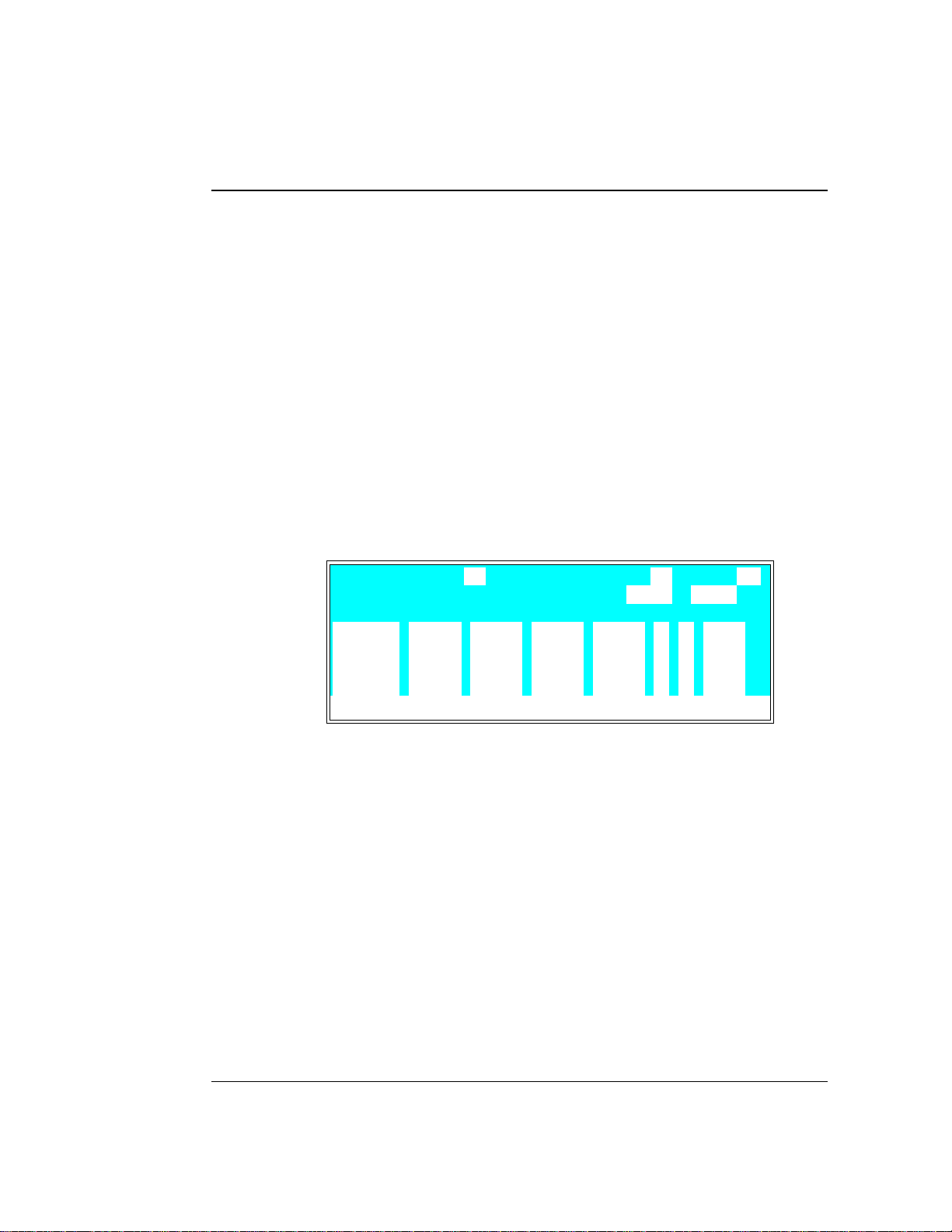
3 • Operation and Maintenance
1. Go to the
EDIT
the
If Method 3 currently exists and you wan t to delete it,
•
move the cursor to
METHOD
screen and enter a method number in
field (3 , for examp le).
TIME = INIT
and press
Delete
twice to
delete the entire Method 3.
If you want to retain the origina l Method 3, enter a
•
new, unused , method number in th e
2. Move to the
FLOW
field of t he
INIT
step and enter a f low rate
EDIT
field .
of 1.50.
Figure 3-13 illustrates the
METHOD
screen as it appears s o
far. You can now begin entering th e method s teps tha t will
generate the curved g radient profile (see Fig ure 3-12).
METHOD EDIT
TIME %A
100.0
0.00
Help Message
%B %C %D V
SAVE TO RU N 033
LIMITs 0 - 5000
C FLOW
_
L 1.50INIT
_
PSI
>
>
>
>
Doc. 034856 -0 3 5/95
Figure 3-13. Curved Gradient Method Example
(After Step 2)
3. Move th e cursor to the %A field of th e
press
Enter
. 100% of eluent A is automatically filled in.
TIME = 0
step and
4. Move the cursor d own to the next line and enter 1 in th e
TIME
field, then move to the %A field and enter 100.
This marks the end of the is ocratic section of the run and
the b egi nn ing of th e eluent B concentration ramp. At this
point, the concentr ation of eluent A begins to decrease from
100% as the concentration of eluent B begins increasing
from 0%.
3-23
Page 68

GP40 Gr adi ent Pu mp
5. Move the cursor d own to the next line and enter 3.5 in th e
TIME
cursor to %B and enter 32.
6. Move th e cursor to the C field and enter 3 to run gradient
curve 3.
After a total of 3.5 minutes (1 minu te of isocratic
conditions plus 2.5 minutes to gr adually decrease th e
amount of eluent A in the mixture while increasing the
amount of eluent B), the eluent comp osition is 68% elue nt
A and 32% eluent B. Figure 3-14 illustrates the
screen as it appears aft er Step 6.
field. Move the cursor to %A and enter 68 . Move the
METHOD
METHOD EDIT
TIME %A
100.0
0.00
1.00 100.0
3.50 68.0 32.0 3
Help Message
(After Completing Step 6)
100.0
Figure 3-14. Curved Gradient Method Example:
%B %C %D V
SAVE TO RU N 033
LIMITs 0 - 5000
C FLOW
_
L 1.50INIT
_
PSI
7. Move the cursor to the next line and enter 6 in the
field. Move the cursor to %B and enter 100.
8. Move th e cursor to the C field and enter 8 .
Aft er a tot al o f 6 m inu tes , the eluent composition is 0%
eluent A and 100% eluent B .
9. Move the cursor to the next line and enter 7 in th e
TIME
field. Move the cursor to %B and enter 100. The eluent
composition remains unchanged at 10 0% eluent B for
1 minute.
>
>
>
>
TIME
3-24
Doc. 034856 -0 3 5/95
Page 69

3 • Operation and Maintenance
10. Move the curso r to the next line and enter 10 in the
field. Move the cursor to %A and enter 100. After a total
of 10 minutes , the concentration of eluent B drops to zero
and the concentr ation of eluent A increas es to 100%.
Figure 3-15 illustrates the completed
11. Move the cursor to the
SA VE TO
field and press
save the method to memory.
METHOD EDIT
TIME %A
3.50 68.0 32.0 3
6.00 100.0
7.00 100.0
10.00 100.0
Help Message
(Complete)
>
Figure 3-15. Curved Gradient Method Example
%B %C %D V
SAVE TO RU N 033
LIMITs 0 - 5000
3. 4. 4 Editin g a Runnin g Method Ex ample
METHOD
C FLOW
8
screen.
Enter
PSI
1.50
TIME
to
>
>
>
>
Doc. 034856 -0 3 5/95
After you enter a method, you can mod ify it by changing ,
adding, or deleting ste ps. If the method you a re editing is
currently running, the changes are n ot executed until you
move the cursor to the
SAVE T O
field and press
Enter
.
The example describe s how to make the following ch anges to
Method 2, the linear gradient example (see Section 3.4.2):
•
Change the eluent compositio n for the
TIME = 15
from 50%
eluent B and 5 0% eluent C to 45% eluent B and 55%
eluent C.
•
Add a step to Method 2 at
TIME = 20.0
to make the eluent
composition 40% e luent B and 60% eluent C.
Figure 3-16 illustrates the
METHOD
screen as it will appear
when editing is complete. Fig ure 3-17 illustrates the edited
gradient profile.
3-25
Page 70

GP40 Gr adi ent Pu mp
METHOD EDIT
TIME %A
10.00
15.00
20.00 40.0 60.0
25.00
Help Message
Figure 3-16. Edited Linear Gradient Method Example:
>
65.0 35.0
>
Figure 3-17. Gradient Profile After Editing
%B %C %D V
45.0 55.0
SAVE TO RU N 222
LIMITs 0 - 5000
C FLOW
2.00
100.0
PSI
>
>
>
>
3-26
This example assumes that the example Method 2 is currently
running.
1. Go to the
METHOD
screen and enter 2 in the
EDIT
field .
2. Move the cu rsor down through Me thod 2 until you r each
TIME = 15
the
step. Move the cursor to %B and enter 45.
Move the cursor t o %C and enter 55.
3. Move th e cursor to the
TIME
field and press
Insert
. Enter
20 in the time field. Move the cursor to %B and enter 40 .
Move the cursor t o %C and enter 60.
4. Move th e cursor to the
5. Press
SCREEN
Menu
and se lect either th e
. Check the status of the method clock :
SA VE T O
field and press
MAIN
screen or
Enter
.
DETA IL
Doc. 034856 -0 3 5/95
Page 71

3 • Operation and Maintenance
If the elapsed time is less than 15 minutes (the time for
•
the first change made to the method), the c hanges will
be incorporated into this run and executed at the
programmed time.
If the elapsed time is greater than 15 minutes, the
•
changes will not be inc orporated into this run. To put
the changes into effect, either press
method clock to the
elapsed time in the
INIT
ial conditions, or enter an
MIN
field that is less than 15 (10,
Reset
to set the
for example). The method w ill restart, using the
parameters programmed for
TIME=10
, and the method
changes will be incorporated at the p rogrammed time.
Doc. 034856 -0 3 5/95
3-27
Page 72

GP40 Gr adi ent Pu mp
3.5 Routine Maintenance
3.5.1 Daily Maintenance
•
When using a co mbination of eluents which contain bo th
salt or base and solvent, rinse the piston frequently or
continuously. Eluent tends to crystallize as the solvent
evaporates; thes e crystals can a brade the p iston and ca use
the main seal to leak . Rinse the pisto n before and after
operation every day as described in the following steps.
1. O pen the low er pump door and locate the two rinse
ports on the front o f each of the pump heads. Eith er
port can be used for rinsing . Figure 3-18 s hows the
typical rinse port connections.
2. Pla ce the end of the rinse wast e tubing into a waste
receptacle. Attach a small syringe containing 5 to
10 mL of deionized water to the rinse inlet female luer
adapter.
3-28
Figure 3-18. Rinsing the Pump Heads
Doc. 034856 -0 3 5/95
Page 73

3 • Operation and Maintenance
3. Inje ct deionized water into the fitting to rinse the
pump heads. The water flows through the first head,
then through the short connecting tubing to rinse the
second head, and out to waste.
4. D ispose of the was te water and close th e door to the
mechani cal chassi s.
•
All components of the vacuum degas assembly are made
of inert materials or corrosion-resistant materials. Dionex
recommends that y ou thoroughly fl ush any chemicals out
of the chambe rs and tubing with d eionized water after
each use to avoid crystallization in the membrane pores.
•
Check the entire mechanical chassis for leaks from the
rinse ports, the eluent manifold connection s and valve s,
the vacuum degas chamber, the bulkhead fittings, and the
eluent rese rvoirs (see Figure 3-19). Tighten or repl ace any
leaking fittings. Wipe up liquid spills and rinse d ried
reagents off the pump components with d eionized water.
Doc. 034856 -0 3 5/95
Figure 3-19. Eluent Flow Sc hematic
3-29
Page 74

GP40 Gr adi ent Pu mp
3.5.2 Periodic Maintenance
•
Replace both the primary and back-up p iston seal s in each
pump head every 6 months, or sooner if you suspect a
leak, op erate the pump co ntinuously, or routinely run at
high pressur e or high flow rates (see Section 5.2) . A drop
of solvent trapped in the end of the drain tub es is normal,
but solvent flowing from the tubing indicates a leak.
Normal friction and wear will gradually cause small leaks
around the piston seals. If the piston seals are not replaced
regularly, these leaks can eventually damage the pump
mechanism, impair operation, and irreversibly damage the
pump.
•
For standard bore ( 100 µL) pumps, replace the filter (P/N
048277) in th e active mixer every 6 months (see
Section 5.7). Particles generated by the mixer can accumulate in the filter, causing erratic or reduced pump output.
3.6 Shutdown
•
Stop the pump by turning off the main power either on the GP40
or at the power source. Omit this step if you are goin g to
maintain a co ntinuous rinse on the pump head s.
•
Rinse the pump p istons before and after daily ope ration to
prevent build-up of salt crystals or other contaminants th at can
damage the pis ton seal (see Section 3 .5.1).
3-30
Doc. 034856 -0 3 5/95
Page 75

3 • Operation and Maintenance
•
If the pump will not b e used for three days or more, flush the
system with deioniz ed water to prevent contaminants from
building up. Or, if this is not p ossible, maintain a continuous
rinse through the system until you resume normal operation.
Select a flow rate of 0.04 mL/min for standard pump heads or
0.01 mL/min for microbore p ump heads, and set all four valves
in the eluent manifold to 2 5% so that the valves are also flushed.
Flushing the eluent manifold is extremely important if your
eluents have a combination of salt or base and solvent. I f
salt precipitates in the valves, the valve diaphragms may
be seriously damaged. If this happens, you will have to
replace the entire valve assembly.
•
If the shutd own is for more than three days, reduce the pr essure
on the eluent r eservoir(s) to approximately 21 KPa (3 psi).
Doc. 034856 -0 3 5/95
3-31
Page 76

GP40 Gr adi ent Pu mp
3-32
Doc. 034856 -0 3 5/95
Page 77

4 • Troubleshooting
4.1 Left-Right Pump Head Pressure Fluctuations . . 4- 3
4.2 Pump Will Not Start . . . . . . . . . . . . . . . . 4-6
4.3 Pump Stops . . . . . . . . . . . . . . . . . . . . . 4-6
4.4 Liquid Leaks/Leak Alarm . . . . . . . . . . . . . 4-9
4.5 Noisy Pump Motor . . . . . . . . . . . . . . . . . 4-11
4.6 Vacuum Degas Pump Does Not Run . . . . . . . 4-12
4.7 Vacuum Degas Pump Calibration F ails . . . . . . 4-13
4.8 Inoperative Relay Control Function . . . . . . . . 4-14
4.9 Poor Chromatographic Reproducibility . . . . . . 4-14
Doc. 034856 -0 3 5/95
4-1
Page 78

GP40 Gr adi ent Pu mp
4-2
Doc. 034856 -0 3 5/95
Page 79

4 • Troubleshooting
This chapter is a guide to troub leshooting common problems tha t
may occur while operating the GP40 Gradient Pump. To use this
guide, turn to the s ection that best des cribes the oper ating problem.
There, you will find the pos sible causes of the problem lis ted in
order of probability. If you cannot eliminate a prob lem on your own,
notify your Dionex office.
If you cannot locate the problem here, refer to Appe ndix C for
instructions on r unning the GP40 dia gnostics program.
4.1 Left-Right Pump Head Pressure Fluctuations
The GP40 display updates the pressure readout once per piston
stroke. A variation of more than 3% from one stroke to the next
indicates a problem.
•
Pump out of prime; there is no eluent
1. Refill the eluent reservoirs. Also make sure that each eluent
line extends to the botto m of the reservoir.
2. Reprime the pump (see Section B.2.7).
•
Pump out of prime; eluents are improperly degassed
1. If the pump is not equip ped with the op tional degas pump
2. If the pump is equipped with the optiona l degas pump
Doc. 034856 -0 3 5/95
assembly, degas the eluents manually (see Section 3.1.1).
Reprime the pump (see Section B.2. 7).
assembly, test the degas pump:
a. O pen the
toggle the
DEGAS STATUS
TEST
field to
scree n. Press a
RUN
and press
Select
Enter
key to
.
b. The pump s hould turn on and r un for approximately 2
minutes. If it does not run, see Section 4.6.
4-3
Page 80

GP40 Gr adi ent Pu mp
• Pump out of prime; eluent bottles are not pressurized
1. Pressurize the bottles (see Section 3.1.3).
2. Reprime the pump (see Section B.2.7).
• Pump o ut of prime; end-line filter is dirty or cl ogged
1. R eplace the filter (P/N 04598 7).
2. Reprime the pump (see Section B.2.7).
• Pump out of prime; air leaks or bloc kages in inlet tubing
1. Chec k and replace any damaged fitting or tubing.
2. Reprime the pump (see Section B.2.7).
• If priming the pump does not eliminate excessive pressure
fluctuations, the piston seal or check valves may be dirty or
defective.
1. Se lect the
compare
DSP STATUS
PISTON PRESSURIZATI ON POINT
screen from the
DIAGNOSTIC MENU
readings; the defective
piston is the one with the higher pressuriza tion point number.
2. Fol low these steps t o isolate the cause:
a. C heck for leaks f rom the piston rins e tubing. If th ere are
no leaks , clean and /or replace the check valves (see
Section 5.1). Dirty check valve s are ca used by impurities
in the eluent. To prevent this in future, install an end-line
filter (P/N 045987) on the end of eac h eluent line in the
reservoirs.
b. If the piston rinse tubing leaks , or if you replace the
check valves but the problem persists, replace the piston
seals (see Sectio n 5.2).
and
4-4
Doc. 034856 -0 3 5/95
Page 81

4 • Troubleshooting
c. Turn off the pump power. Us ing a 7-mm open -end
wrench, lo osen the loc k on the mecha nical chassis
drawer. The lock is on th e lower right side of the
chassis, between valves 3 and 4 (see the label on the
inside of the lower door). Pull the drawer out abo ut
four inches. Turn on the pump and observe the
pistons. Both pistons should move. If they do n ot, the
rocker arm spring is broken. Notify your Dionex office.
Observe the warning label on the inside of the lower doo r.
The arrows on the label indicate moving mechanical par ts
that present pinch hazards when the pump i s on and the
mechanical drawer i s open. Do not touch any parts within
the mechanical chassis while the pump is on.
d. If the pistons move, then one or both may be b roken
or scratched. In this ca se, turn off the power, remove
the pump head and examine the piston. If it is broken,
replace i t (see Section 5 .3).
Doc. 034856 -0 3 5/95
e. If a piston moves slightly and th en breaks contact with
the rocker a rm follower, replace the piston se al (see
Section 5.2); it is too tight. (The rocker arm follower
is the cylinder that holds the piston in place a s it
moves in and out of the pump head ass embly. I t has a
magnet, which holds the piston .)
f. Push the mec hanical chas sis drawer b ack in place,
making sure th e cables are not p inched. Retighten the
drawer lock. Turn on the power.
4-5
Page 82

GP40 Gr adi ent Pu mp
4.2 Pump Will Not Start
• Flow rate is set to zero
Reset the flow rate (see Se ction 2.4.2).
• While being primed, pump starts briefly; then s tops because
of high pressure limit
Open the pr essure trans ducer waste valve b y turning the knob
counterclockwis e two turns (see Figure B-5).
4.3 Pump Stops
• Method or other remote input instructed the pump to stop
Check the display screen for error messages. If none are
displayed, the pump was probably instr ucted to stop by the
method, comput er, or other remote signal sour ce.
• Electrical cables improperly installed
4-6
1. Pla ce the pump in
Off/On
to start the pump.
LOCAL
mode,
DIRECT C ONTROL
. Press
2. If a non-zero flow rate is displayed and the keypad LED is
ON, verify that the ele ctrical cables i n the mecha nical chassi s
are properly ins talled.
a. To access the mechanical chass is, first turn off the pump
power.
b. Using a 7-mm open-end wrench or your fingers, loosen
the lock on the mechani cal chassis drawer. The lock is on
the lower right side of the chassis, between valves 3 and 4
(see the label on the ins ide of the lower door).
c. Pull the drawer out a few inches.
d. C heck that all cables a re seated prope rly in the connec tors
on the distribution card located on the top of the
mechani cal chassi s.
Doc. 034856 -0 3 5/95
Page 83
4 • Troubleshooting
e. Pu sh the mechanical chas sis drawer bac k in place, making
sure the cables are not pinched. R etighten the drawer
lock. Turn on the power.
• Low pressure limit was tripped. The following message is
displayed:
Low Pressure Limit Violation
1. Verify that eluent is present in the channel se lected. If th e
eluent reservoir is empty, refill it or select a channel which
does have eluent. Prime the pump (see Sectio ns B.2.7
and B.2.7) before resuming oper ation.
2. M ake sure th e waste valve on t he pressu re transducer is
closed (i.e. , turn the knob o n the pressu re transducer ho using
clockwise as shown in Figure B-5).
Overtightening the pressure transducer waste valve may
damage the valve and the pressure transducer housi ng.
3. M ake sure th ere are no l iquid leaks in the fl ow system.
4. Pla ce the pump in
LOCAL, DIRECT C ONTROL
. Press
Off/On
start th e pump and ver ify that the p istons ar e moving and that
you can h ear the pump. If y ou hear the pump but the pistons
are not moving, the main spring on the pump is bro ken. If
there is no sound from the pump, check the LED on the CPU
card insi de the door to the electronics ch assis. A r ed LED
indicate s a defective power supply. Replace the power supply
(P/N 046440) (see Figure 2-6) . Contact your Dionex office
for help.
to
Doc. 034856 -0 3 5/95
4-7
Page 84

GP40 Gr adi ent Pu mp
5. With the pump r unning, open the
DSP STATUS
screen and no te
whether the left-right pressure varies by more th an 3%
between strokes . If it does, refer to Section 4.1. If it does not,
either increase the flow rate or reduce the low pressure limit
setting and continue operation.
• High pressure limit was tripped. The following message is
displayed:
High Pressure Limit Violation
1. Repla ce any crimped or bloc ked tubing downstream from th e
pressure trans ducer. If there is none, go on to Step 2.
2. O pen the pressure transducer waste valve by tur ning the knob
counterclockwise about two turns as shown in Figure B-5.
Check the pr essure reading; if it is above 97 KPa (14 ps i),
recalibrate the pressure transducer (see Section C.3.6).
3. Select a lower flow rate or, if it is safe to do so, increase the
high pressure limit.
• An error message beginning with “DSP” displays:
4-8
There are several messag es related to Digital Signal Pr ocessor
(DSP) errors, for example, “DSP communication fails” and “DSP
does not acknowledge.” These are all treated s imilarly:
1. Power down by pres sing the power switch. Verify that the
DSP card is present and is properly installed in slot 1 of the
electronic s chassis card cage (see Figu re 2-6).
Doc. 034856 -0 3 5/95
Page 85

4 • Troubleshooting
2. Power up by pressing the power switch. The DSP error
message shou ld not reappear; if it does, notify your Dionex
office. The power supply (P/N 0 46440), DSP card
(P/N 045369) , or CPU card (P/N 046340) may n eed replacing.
Do not remove any of the electronic cards from the detector.
There are no user-serviceable components on t he cards.
If serv icing i s requir ed, it must be p erformed by qual ified
personnel and appropriate electrostatic discharge (ESD)
handling proc edures must be followed .
• The following error mes sage displays:
Motor Drive Fails
If the pump motor is in a runaway condition, the motor
automatically shuts off and the above error message is displa yed.
Contact your Dionex office.
• The following error mes sage displays:
Encoder index not found
1. Power down by pres sing the power switch. Verify that the
cables connected to the DSP card in the electronics chass is
(see Fi gure 2-6) are s eated prop erly.
2. Power up by pressing the power switch. The erro r message
should not reappear; if it does, notify you r Dionex office.
4.4 Liquid Leaks/Leak Alarm
• Leaks from the front or rear of the piston head indicate a
defective pis ton seal
Replace th e piston s eal (see Secti on 5.2). I f liquid is leaking
from the rear of the piston, also replace the piston b ackup seal
(see Section 5.2).
Doc. 034856 -0 3 5/95
4-9
Page 86

GP40 Gr adi ent Pu mp
• Leaks from any connection between the eluent reservoir and
the pump heads indicates an eluent leak (s ee Figure 3-19)
Tighten the fitting connections just enough to s top the leak.
Overtightening the fitting connections may strip the threads
in the valve block. If this happens, replace the entire
manifold assembly (P/N 046203).
• Proportioning valve lea ks
Tighten loose fittings, or if there are no loose fitting s, replace the
valve (see Section 5.6).
• Pressure t ransducer lea ks
Inspect th e pressur e transd ucer. If the wast e valve is the s ource
of the leak, replace the was te valve O-ring (s ee Section 5.5). If
the leak is from the r ear of the tr ansducer, repla ce the press ure
pad and O-rin g (see Section 5. 4).
4-10
• Priming valve and/or tee manifold leaks
Tighten any leaking fittings just enough to stop the leak. Also,
verify that the small lever on the priming block is pushed all the
way to the right (se e Figure B-5). If this do es not stop the leak,
replace the priming b lock assembly (P/N 045730).
• Interior mechanical chas sis leaks
1. To access the mechanical chass is, first turn off the pump
power. Using an 7-mm open-end w rench or your fingers,
loosen th e lock on the mechanical chas sis drawer. The lock is
on the lower right side of the chassis, between valves 3 and 4
(see the label on the ins ide of the lower door). Pull the
drawer out a few inches.
2. Ins pect for leaks and tighten any leaking fittings just enough
to stop the lea k. If the leak is c aused by a damaged part,
replace the par t.
Doc. 034856 -0 3 5/95
Page 87

4 • Troubleshooting
3. Pus h the mechan ical chass is drawer back in place, ma king sure
the cables are not pin ched. Retig hten the drawer l ock.
4.5 No isy Pump Motor
• DSP (digital signal processing) card current limit has been
exceeded . The card includes a built -in current limit er to
protect the motor and motor drive.
Check the three small LEDs in th e upper left corner of the DSP
card bulkhead. The DSP card is located be hind the pump upper
door in the electr onics chassis . If the LEDs ar e flashing in time
with the pump strokes, the current limiter is b eing activa ted. As
the pump motor ages, it beco mes less efficient and the current
limit is activated more frequently. Activating the current limit is
harmless, but if it occurs frequently, even at low speeds and /or
pressures, the bo ttom plate assembly (P/N 045670) need s to be
replaced. Ca ll your Dionex o ffice for assistan ce.
• Hardware p ressure limit has been exceede d. This ind icates
excessive pressure transduc er offset .
The DSP hand les offset corr ection but the h ardware has no
correction. Replace the pre ssure transducer (P/N 045731). Call
your Dionex office for assistanc e. After replacing the transducer,
recalibrate t he pressu re slope and offset (see Secti on C.3.6).
• Pressure servo oscillation
Check th e
DSP STATUS
screen t o verify th at the correc t pump
head volume and head material are selected. If the setting s are
correct but the problem per sists, notify yo ur Dionex office.
• Out of prime
Check th e
DSP STATUS
screen and verify that there is less than
3% variation between the left and right pressurization po ints. If
not, prime the pump (see Section B.2.7).
Doc. 034856 -0 3 5/95
4-11
Page 88

GP40 Gr adi ent Pu mp
4.6 Vacuum Degas Pump Does Not Run
DEGAS OPTIONS
•
screen sett ings inco rrect
Open the
DEGAS OPTIONS
sure that the
select
BY SETTING
screen (press
DEGAS PUMP
field is not set to
and then en ter the desir ed cycle duration an d
Menu
, and 4) and make
ALWAYS OFF
. If it is,
frequency times (see Section C.1 .5). By default, the pump run s 2
min at sta rt-up, and t hereafter, every 10 min for 3 0 sec.
• Electrical cables improperly installed
Manually test the degas pump.
1. O pen the
Press a
Enter
Select
.
DEGAS STATUS
key to toggle the
screen (press
TEST
Menu, 8, 8
field to
, and 3).
RUN
and press
2. The pump should turn o n and run fo r the cycle duration time
specified in the
DEGAS OPTIONS
screen (2 minutes by default).
If it does no t run, verify that the c ables connected to the
pump in the electroni cs chassis (s ee Figure 2-6) and in the
mechanical chassis are properly co nnected.
a. To access the mechanical chass is, first turn off the pump
power.
b. Using a 7-mm open-end wrench or your fingers, loosen
the lock on the mechani cal chassis drawer. The lock is on
the lower right side of the chassis, between valves 3 and 4
(see the label on the ins ide of the lower door). Pull the
drawer out a few inches.
4-12
c. C heck that all c ables are seated properly in th e connector s
on the distribution card located on the top of the
mechani cal chassi s.
d. If the connectio ns are corre ct, the distribution card
(P/N 045714) may need to be r eplaced. Call your Dionex
office for assistan ce.
e. Pu sh the mechanical chas sis drawer bac k in place, making
sure the cables are not pinch ed. Retighten the drawer lock .
Doc. 034856 -0 3 5/95
Page 89

4 • Troubleshooting
4.7 Vacuum Degas Pump Calibration Fa ils
At the end of the degas cali bration, th e
DEGAS READIN G
value is
less than 130 00 and one of the following error messag es appears:
Degas vacuum pump is not present or degas
circuitry is malfunctioning.
Vacuum Degas Fails
Verify that the cable to the vacuum degas pump is conne cted to
the distr ibution card in the mechan ical chass is.
1. Turn off the power.
2. U se a 7-mm open-end w rench or your fingers to loosen the
lock on th e mechanical cha ssis drawer. The lock is on th e
lower right side of the chassis, between valves 3 and 4. Pull
the drawer ou t a few inches.
3. The distribution card is on the top of the mechanical chassis.
Labels printed on the card identify the various cables plugge d
into it. The connector for th e vacuum degas pump, labeled
VAC PU M P
, is near th e right rear corner of the card. Check the
connection.
4. Pu sh the mechanical chas sis drawer bac k in place, making
5. Retr y the calibration. If the message reappear s, notify your
Doc. 034856 -0 3 5/95
sure the cables are not pinch ed. Retighten the drawer lock .
Turn on the power.
Dionex office.
4-13
Page 90

GP40 Gr adi ent Pu mp
4.8 Vacuum Degas Pump Low Vacuum
The GP40 monitors t he degas vacuum reading every 1 min. I f
the degas vacuum is lower than the monitoring value, the degas
pump turns on. When the pump turns off, if the vac uum reading
is 2000 or mo re lower than the monitoring value, the following
message displays:
LOW VACUUM ALARM!!
Check DEGAS OPTIONS settings or refer to
service manual
Open the
CYCLE DURATION
the
CYCLES
DEGAS OPTIONS
. If adjusting these settings does not solve the problem,
screen (press
time and/or decreasing the
Menu
, and 4). Try increasing
TIME BETWEEN
contact your Dion ex offi ce.
4.9 Inoperative Relay Control Function
• Incorrectly installed cables
Make sure the cables between the appropriate relay function and
the input or output unit a re properly connected (s ee Appendix E).
• Method programming error
Refer to Chapter 2 and Appendix C.
• When attempting to set TTL2, the following message displays:
TTL2 is set to indicate FLOW/NO FLOW.
TTL2 OUTPUT USAGE
The
field on the
currently set to signal when p ump flow stops (
setting is used to control the power to a Self-Regenerating
Suppressor (SRS). To use TTL2 f or another function, open the
PUMP OPTIONS
NORMAL
.
screen and set the
PUMP OP TION S
TTL2 OUTPUT USAGE
screen i s
0 FLOW
). Th is
field to
4-14
Doc. 034856 -0 3 5/95
Page 91

4 • Troubleshooting
4.10 Poor Chromatographic Reproducibility
• Liquid lines incompletely flushed after an eluent change
Attach a syringe to the p riming block and draw at least 2 .5 mL
(10 mL if the vacuum degas assembly is not installed) of the new
eluent through the liquid lines befor e beginning operation.
• Leaking piston s eal
Check for liquid leaks at the rinse ports in the front of the pump
heads. Repl ace the pist on seal on any h ead with a leak (see
Section 5.2).
• Malfunctioning proportioning valve
Test the valves (see Section C.2.8). If a test fails, the
proportioning valve asse mbly may need to be replaced (see
Section 5.6).
Doc. 034856 -0 3 5/95
4-15
Page 92

GP40 Gr adi ent Pu mp
4-16
Doc. 034856 -0 3 5/95
Page 93

5 • Service
5.1 Cleaning the Check Valves . . . . . . . . . . . . . 5-3
5.2 Piston Seal Replacement . . . . . . . . . . . . . . 5-6
5.3 Pump Piston Replacement . . . . . . . . . . . . . 5-10
5.4 Pressur e Transducer Pad and O-Ring
Replacement . . . . . . . . . . . . . . . . . . . . . 5-11
5.5 Pressur e Transducer Waste Valve O-Ring
Replacement . . . . . . . . . . . . . . . . . . . . . 5-13
5.6 Proportioning Valve Replacement . . . . . . . . . 5-14
5.7 Active Mixer Filter Replacement . . . . . . . . . 5-16
5.8 Changing Main Power Fuses . . . . . . . . . . . . 5-19
Doc. 034856 -0 3 5/95
5-1
Page 94

GP40 Gr adi ent Pu mp
5-2
Doc. 034856 -0 3 5/95
Page 95

5 • Service
This chapter des cribes service a nd repair procedur es for the
mechanical com ponents of the GP40. Each procedure spe cifies the
problem it is intended to eliminate. Before replacing any part, refer
to the troubleshooting information in Chap ter 4 to isolate the cause
of the problem. W hen ordering replacemen t parts, pleas e include the
model and serial numb er of the pump.
Substituting non-Dionex pa rts may impair detector performance,
thereby voiding the product warranty. Refer to the warranty
statement in the Dionex Terms and Conditions for more information .
NOTE
The pump’s elect ronic components are no t cu s t o mer-serv iceable.
Repair of electro nic components mus t be performed by Dionex.
5.1 Cleaning the Check Valves
A dirty check valve causes a n erratic f low rate and may cause
the pump to lose prime and/or be difficult to reprime.
1. Turn off the main power switch, to prevent the pump from
starting inadvertently.
2. Disco nnect the tube fittings from the inlet a nd outlet check valve
housings (s ee Figures 5-1 and 5 -2).
3.
Use a 12-mm (
housings. Carefully remove the check valve cartridges from the
housings.
4. Plac e the check valve housings and cartridges in a beaker with
methanol, and sonicate or agita te for several minutes.
5. R inse each check valve housing and cartridge th oroughly with
filtered deionized water.
Doc. 034856 -0 3 5/95
1
⁄
-inch) wrench to loosen b oth check valve
2
5-3
Page 96

GP40 Gr adi ent Pu mp
Pressure Transducer
Outlet Check Valve
Pump Head
To Column
To Eluent Manifold
Inlet Check
Valve
To Wast e
Figure 5-1. Pump Heads and Liquid Lines (PEEK)
Pressure T ransducer
To Column
Outlet Check Valve
Pump Head
To Eluent
Manifold
Inlet Check
Valve
To Wast e
5-4
Figure 5-2. Pump Heads and Liquid Lines (SST)
Doc. 034856 -0 3 5/95
Page 97

5 • Service
6. The inlet check valve assembly housing has a 1/4-28 port.
Replace the cartridge in the inlet check valve hous ing; the
double-hole en d of the cartridg e should be vi sible. The outlet
check valve assembly housing has a 10- 32 port. Replac e the
cartridge in the outlet check valve housing; the single-hole end
of the cartridg e visible. Liq uid flows through the c heck valve in
the large single hole and o ut the small double holes.
7. Reins tall the check valves. Make su re that the in let check valve
is installed on the bottom of the head and that the outlet check
valve is installed on the top of the head. Tighten only eno ugh to
seat (25 in-lb torque). Tighten a little more only if it leaks.
Overtightening may damage the pump head and t he check
valve housing and crush the check valve seats.
8. Recon nect the liquid lines. Turn on the main power.
9. Prime the pu mp (see Section B.2.7). If the pump w ill not prime
and all other p ossible causes of the problem have been
eliminated, rep lace the cartridge c ontaining the ch eck valve.
Check Valv e Cartridge Type Part Number
Standa rd B o re PEEK 047747
Stand ard Bor e Stai nless Steel 047755
Microbor e PEEK 047748
Microbore Stainless Steel 048279
10. A fter replacin g check valve cartri dges, open the
screen (choice 2 of the
VALVES IN USE
the
field and press
DIAGNOSTIC MENU
Enter
to reset the field to 0
). Move the cursor to
ELAPSED TIME
cycles.
Doc. 034856 -0 3 5/95
5-5
Page 98

GP40 Gr adi ent Pu mp
5.2 Piston Seal Replacement
A damaged seal allows leakage past the piston and then through
the rinse ports in the front of the pump heads. Flow rates will be
low and erratic, producing chromatograms with longer than
normal retenti on times.
1. Turn off the main power switch.
2. Disco nnect the tube fittings from the pres sure transducer and the
inlet check valve (s ee Figures 5 -1 and 5-2).
3. R emove the two nuts from the pump head.
4. C arefully disengage the head from the piston by pulling th e head
straight off and away from its mo unting guides.
Lateral motion while disenga ging the head from the piston
may break the piston. If the piston is broken, be very careful
when removing it; broken pistons have sharp edges and
can cause cuts.
5-6
5. Plac e the head (f ront end down) on a clean work su rface and lift
off the backup washe r to expose the p iston guide (see
Figures 5-3 an d 5-4).
6. The pistons are captured by a magnetic retention system a nd do
not come off as part of the pump head assembly. After removing
the pump head, apply just enoug h lateral force to overcome the
magnetic field and release the pistons.
Doc. 034856 -0 3 5/95
Page 99

Outlet Check Valve
Pump Head
O-Ring
Back-up Seal
Piston Seal
Inlet Check Valve
Piston Guide
Figure 5-3. Pump Head Assembly
5 • Service
Piston
Backup Washer
Component Standard
Bore/PEEK
Standard
Bore/SST
Microbore/
PEEK
Microbore/
SST
Pump Head Assembly 045668 046313 045784 046342
Pump Head 047406 047409 047423 047414
Outlet Check Valve 047661 047665 047657 047663
Inlet Chec k Valve 047660 047664 047656 047662
Piston Seal 04758 3 04 7583 048526 048526
Piston Guide 04563 3 04 5633 045632 045632
Backup Sea l 04872 2 04 8722 048721 048721
O-Ring 01489 5 01 4895 014895 014895
Backup Washer 045630 045630 045631 045631
Piston 045386 045386 045 387 045387
Table 5-1. Pum p Head Assembly Par t Numbers
Doc. 034856 -0 3 5/95
5-7
Page 100

GP40 Gr adi ent Pu mp
7. To remove the piston guide an d seal:
a. Fill the head cavity with deionized water by injecting through
either the piston opening or the inlet check valve.
b. Reinsert the piston appro ximately 1/8-in into the seal (see
Figure 5-4).
c. Ins tall 10-32 fitting plugs (P/N 042772) on th e inlet and
outlet check valves. Tighten the plugs.
d. Pu sh the piston into the head. This action will hydraulic ally
unseat the seal and pis ton guide from the head. Remove the
pisto n and pull off the g uide and seal.
e. If the piston guide and seal do not come out, make sure the
10-32 plugs are tight. Then , add more water and repeat Steps
b and d.
f. Remove the 10-32 fitting plugs .
5-8
Pump
Head
Inlet C he ck
Valve
Outlet Check
Valve
1/4-28 Fitting Plug
(P/N 037628)
Figure 5-4. Removing the Piston Seal
10-32 Fitting Plug
(P/N 042772)
Push in to
unseat the seal
and piston guide.
Backup Wash er
(Rem ove)
Piston
Piston
Seal
Remove the piston from the
head and p ull of the seal
and piston guide.
Guide
Doc. 034856 -0 3 5/95
 Loading...