

Page 1

DX-120 ION CHROMATOGRAPH
OPERATOR’S MANUAL
© 1998 Dionex Corporatio n
Document No . 031183
Revision 03
September 1998
Page 2

©1998 by Dionex Corpor ation
All rights reserved worldwide.
Printed in the United States of America.
This publication is protected by federal copyright law. No part of this publication
may be copied or distributed, transmitted, transcribed, stored in a retrieval system,
or transmitted into any human or computer language, in any form or by any means,
electronic, mechanical, magnetic, manual, or otherwise, or disclosed to third parties
without the express written permission of Dionex Corporation, 1228 Titan Way,
Sunnyvale, California 94088-36 03 U.S.A.
DISCLAIMER OF WARRANTY AND LIMITED WARRANTY
THIS PUBLICATION IS PROVIDED “AS IS” WITHOUT WARRANTY OF
ANY KIND. DIONEX CORPORATION DOES NOT WARRANT,
GUARANTEE, OR MAKE ANY EXPRESS OR IMPLIED
REPRESENTATIONS REGARDING THE USE, OR THE RESULTS OF THE
USE, OF THIS PUBLICATION IN TERMS OF CORRECTNESS,
ACCURACY, RELIABILITY, CURRENTNESS, OR OTHERWISE.
FURTHER, DIONEX CORPORATION RESERVES THE RIGHT TO REVISE
THIS PUBLICATION AND TO MAKE CHANGES FROM TIME TO TIME
IN THE CONTENT HEREINOF WITHOUT OBLIGATION OF DIONEX
CORPORATION TO NOTIFY ANY PERSON OR ORGANIZATION OF
SUCH REVISION OR CHANGES.
EMISSIONS COMPLIANCE
This equipment meets ITE standard EN 55022 part A for radiated emissions and is
suitable for use in a laboratory environment. Operation of this equipment in a
residential area, however, may cause interference to radio and television reception.
TRADEMARKS
Teflon® an d Tefzel® are registered t rademarks of E.I. du Pont de Ne mours & Co.
AutoSuppression, DX-LAN, IonSep®, MPIC®, OmniPac®, OnGuard,
Self-Regenerating Suppressor, and SRS are trademarks of Dionex Corp.
PRINTING HISTORY
Revision 01, May 1996
Revision 02, March 1997
Revision 03, September 1998
Page 3

Contents
1 • Introduction
1.1 About This Manual . . . . . . . . . . . . . . . . . 1-2
1.1.1 Typefaces and Conventions . . . . . . . . 1-3
1.1.2 Safety Messages and Notes . . . . . . . . 1-4
1.1.3 Symbols . . . . . . . . . . . . . . . . . . . 1-5
1.2 Related Manuals . . . . . . . . . . . . . . . . . . . 1-5
2 • Description
2.1 Operating Features . . . . . . . . . . . . . . . . . 2-1
2.1.1 Front Control Panel . . . . . . . . . . . . 2-3
2.1.2 Pump . . . . . . . . . . . . . . . . . . . . 2-6
2.1.3 Configuration DIP Switches . . . . . . . 2-6
2.1.4 Eluent Reservoirs . . . . . . . . . . . . . 2-7
Doc. 031138-03 9/98
2.1.5 Component Panel . . . . . . . . . . . . . 2-8
2.1.6 Rheodyne Injection Valve . . . . . . . . . 2-11
2.1.7 Detector Cells . . . . . . . . . . . . . . . 2-12
2.1.8 DS4 Detection Stabilizer . . . . . . . . . 2-13
2.2 Dual-Column Configuration Features . . . . . . . 2-15
2.2.1 Column Select Mode . . . . . . . . . . . 2-16
2.2.2 Eluent Select Mode . . . . . . . . . . . . 2-18
2.3 Fluid Schematics . . . . . . . . . . . . . . . . . . 2-19
2.4 Control Modes . . . . . . . . . . . . . . . . . . . . 2-22
2.4.1 Local Mode . . . . . . . . . . . . . . . . . 2-22
2.4.2 Remote Mode . . . . . . . . . . . . . . . 2-22
i
Page 4

DX-120 Operator’s Manual
2.5 TTL Control . . . . . . . . . . . . . . . . . . . . . 2-23
2.5.1 Injection Valve/Remote Start Control . . 2-23
2.5.2 Recorder Range Control . . . . . . . . . . 2-23
3 • Operation and Maintenance
3.1 Preparing Eluents . . . . . . . . . . . . . . . . . . 3-1
3.1.1 Degassing Eluents . . . . . . . . . . . . . 3-1
3.1.2 Filtering Eluents . . . . . . . . . . . . . . 3-2
3.1.3 Pressurizing Eluent Reservoirs . . . . . . 3-2
3.2 Preparing Samples . . . . . . . . . . . . . . . . . 3-3
3.2.1 Collecting and Storing . . . . . . . . . . . 3-3
3.2.2 Pretreating . . . . . . . . . . . . . . . . . 3-3
3.2.3 Diluting . . . . . . . . . . . . . . . . . . . 3-4
3.3 Operating . . . . . . . . . . . . . . . . . . . . . . 3-5
3.3.1 Starting Up . . . . . . . . . . . . . . . . . 3-5
3.3.2 Injecting the Sample . . . . . . . . . . . . 3-7
3.4 Using an Integrator . . . . . . . . . . . . . . . . . 3-9
3.5 Running under PeakNet Control . . . . . . . . . . 3-9
3.6 Optimizing Temperature Compensation . . . . . . 3-10
3.6.1 With a DS4 . . . . . . . . . . . . . . . . . 3-10
3.6.2 With a CDM-3 Cell . . . . . . . . . . . . 3-10
3.7 Maintenance . . . . . . . . . . . . . . . . . . . . . 3-11
4 • Troubleshooting
4.1 Alarms . . . . . . . . . . . . . . . . . . . . . . . . 4-1
4.2 Error Codes . . . . . . . . . . . . . . . . . . . . . 4-3
4.3 Liquid Leaks . . . . . . . . . . . . . . . . . . . . . 4-4
4.4 Pump Difficult to Prime . . . . . . . . . . . . . . 4-8
ii
Doc. 031138-0 3 9/98
Page 5

4.5 Pump Loses Prime . . . . . . . . . . . . . . . . . 4-8
4.6 Pump Does Not Start . . . . . . . . . . . . . . . . 4-9
4.7 No Flow . . . . . . . . . . . . . . . . . . . . . . . 4-9
4.8 Excessive System Backpressure . . . . . . . . . . 4-9
4.9 Peak “Ghosting” . . . . . . . . . . . . . . . . . . . 4-10
4.10 Nonreproducible Peak Height or Retention
Time . . . . . . . . . . . . . . . . . . . . . . . . . 4-11
4.11 Abnormal Retention Time or Selectivity . . . . . 4-11
4.12 DS4 Temperature Inaccurate . . . . . . . . . . . . 4-12
4.13 No Detector Response . . . . . . . . . . . . . . . 4-13
4.14 Low Detector Output . . . . . . . . . . . . . . . . 4-14
4.15 High Detector Output . . . . . . . . . . . . . . . . 4-14
4.16 Noisy or Drifting Baseline . . . . . . . . . . . . . 4-15
5 • Service
Contents
Doc. 031138-03 9/98
5.1 Replacing Tubing and Fittings . . . . . . . . . . . 5-2
5.2 Changing the Sample Loop . . . . . . . . . . . . 5-2
5.3 Isolating a Restriction in the Liquid Plumbing . . 5-3
5.4 Replacing the DS4 Cell . . . . . . . . . . . . . . . 5-3
5.5 Cleaning Cell Electrodes . . . . . . . . . . . . . . 5-5
5.6 Calibrating the Cell Constant . . . . . . . . . . . 5-6
5.7 Calibrating the Pump Flow Rate . . . . . . . . . . 5-8
5.8 Cleaning and Replacing Pump Check Valves . . . 5-8
5.9 Replacing a Pump Piston Seal . . . . . . . . . . . 5-9
5.10 Replacing a Pump Piston . . . . . . . . . . . . . . 5-12
5.11 Replacing the Pressure Transducer Waste
Valve O-Ring . . . . . . . . . . . . . . . . . . . . 5-14
5.12 Changing the Main Power Fuses . . . . . . . . . . 5-15
iii
Page 6

DX-120 Operator’s Manual
A • Specifications
A.1 Electrical . . . . . . . . . . . . . . . . . . . . . . . A-1
A.2 Environmental/Physical . . . . . . . . . . . . . . . A-1
A.3 Control Panel . . . . . . . . . . . . . . . . . . . . A-2
A.4 Pump . . . . . . . . . . . . . . . . . . . . . . . . . A-2
A.5 Pulse Damper . . . . . . . . . . . . . . . . . . . . A-2
A.6 Detector . . . . . . . . . . . . . . . . . . . . . . . A-2
A.7 Conductivity Cell . . . . . . . . . . . . . . . . . . A-3
A.8 DS4 Detection Stabilizer (Optional) . . . . . . . . A-3
A.9 Valves . . . . . . . . . . . . . . . . . . . . . . . . A-3
A.10 Delay Volume . . . . . . . . . . . . . . . . . . . . A-4
B • Installation
B.1 Facility Requirements . . . . . . . . . . . . . . . . B-1
iv
B.2 Installation Overview . . . . . . . . . . . . . . . B-1
B.3 Rear Panel Connections . . . . . . . . . . . . . . B-2
B.3.1 Power Connection . . . . . . . . . . . . . B-2
B.3.2 Switched AC Outlet Connection
(Optional) . . . . . . . . . . . . . . . . . . B-4
B.3.3 Waste Lines . . . . . . . . . . . . . . . . . B-5
B.3.4 Gas Connection . . . . . . . . . . . . . . B-5
B.3.5 DX-LAN Cable Connection (Optional) . B-6
B.4 Eluent Reservoir Connections . . . . . . . . . . . B-8
B.5 Pump Setup . . . . . . . . . . . . . . . . . . . . . B-8
B.5.1 Priming the Pump . . . . . . . . . . . . . B-8
B.5.2 Checking the Pump Flow Rate
Calibration . . . . . . . . . . . . . . . . . B-9
Doc. 031138-0 3 9/98
Page 7

Contents
B.6 Connections to Chromatography Components . . B-10
B.6.1 Backpressure Requirements . . . . . . . . B-12
B.6.2 Self-Regenerating Suppressor (SRS)
Installation . . . . . . . . . . . . . . . . . B-13
B.6.3 Column Installation . . . . . . . . . . . . B-17
B.7 TTL Control Connections (Overview) . . . . . . . B-19
B.7.1 TTL Inputs . . . . . . . . . . . . . . . . . B-19
B.7.2 TTL Outputs . . . . . . . . . . . . . . . . B-20
B.7.3 F errite Core Installation on TTL Output
Cables . . . . . . . . . . . . . . . . . . . . B-21
B.8 Autosampler Connections (Optional) . . . . . . . B-22
B.8.1 Autosampler Outlet Line Connection . . B-22
B.8.2 AS40 Automated Sampler Connections . B-22
B.8.3 AS3 500 Automated Sampler
Connections . . . . . . . . . . . . . . . . B-24
B.9 Recorder and Integrator Connectio ns
(Optional) . . . . . . . . . . . . . . . . . . . . . . B-27
C • Integrator Programming
Doc. 031138-03 9/98
B.9.1 Chart Recorder Connections . . . . . . . B-27
B.9.2 4400 or 4600 Integrator Connections . . B-27
B.10 Configuration DIP Switch Settings . . . . . . . . B-29
B.11 DS4 Detection Stabilizer Installation . . . . . . . B-33
B.12 CDM-3 Cell Installation . . . . . . . . . . . . . . B-35
B.13 Injection Valve Connections . . . . . . . . . . . . B-36
B.14 Column Switching Valve Connections . . . . . . . B-37
B.15 DX-LAN Card Installation (Optional) . . . . . . . B-38
C.1 Integrator Power-up Configuration . . . . . . . . C-1
C.2 Setting Offsets . . . . . . . . . . . . . . . . . . . . C-2
C.3 Area Percent Mode . . . . . . . . . . . . . . . . . C-2
v
Page 8

DX-120 Operator’s Manual
C.4 Using DIALOG to Create a Method . . . . . . . . C-3
C.4.1 Time Functions . . . . . . . . . . . . . . . C-3
C.4.2 Creating a Method . . . . . . . . . . . . . C-4
C.5 BASIC Programming . . . . . . . . . . . . . . . . C-7
D • Conductivity Detection
D.1 How Conductivity Is Measured . . . . . . . . . . D-1
D.2 Conductivity of Solutions . . . . . . . . . . . . . D-2
D.2.1 Effect of Hydration Sphere and
D.2.2 Effect of Temperature on Condu ctivity . D-4
D.2.3 Species Detected by Conductivity . . . . D-5
D.2.4 Chemical Suppression . . . . . . . . . . . D-6
D.2.5 Eluents for Conductivity Detection . . . D-9
Solvent on Conductivity . . . . . . . . . . D-4
vi
E • Glossary
Doc. 031138-0 3 9/98
Page 9

1 • Introduction
The Dionex DX-120 Ion Chro matograph performs isocratic ion
analysis applications using conductivity detection. The DX-120 is an
integrated system, which includes a pump, detector, and injection
valve. The chromatography components, including the column(s),
Self-Regenerating Suppressor (SRS), and conductivity cell are
ordered separately. These components are moun ted on the inside of
the DX-120 door.
The DX-120 can be controlled locally, using the front panel keypad
and display, or remotely, from a PeakNet workstation. The PeakNet
workstation consists of a computer with a Dionex DX-LAN
interface card and PeakNet software (Release 4.30 or higher)
installed. Limited remote control is also available using TTL signals.
The DX-120 can be ordered as a single-column system or a
dual-column system. The dual-column system a llows switching
between two sets of columns (column select mode) or b etween two
eluents (eluent select mode). In the eluent select mode, the DX-120
can perform step gradients.
The following models are available:
Configuration Voltage/Line Frequency* Without
Single-column 115 VAC/60 Hz P/N 050100 P/N 050200
Dual-column 115 VAC/60 Hz P/N 050102 P/N 0502 02
*Must match the voltage and line frequency of the installation site’s
power source.
Doc. 031183-03 9/98
With
DX-LAN
100 VAC/50 Hz P/N 050103 P/N 0502 03
230 VAC/50 Hz P/N 050106 P/N 0502 06
100 VAC/50 Hz P/N 050105 P/N 0502 05
230 VAC/50 Hz P/N 050108 P/N 0502 08
DX-LAN
1-1
Page 10

DX-120 Operator’s Manual
1.1 About This Manual
Chapter 1
Introduction
Chapter 2
Description
Chapter 3
Operation and
Maintenance
Chapter 4
Troubleshooting
Chapter 5
Service
Appendix A
Specifications
Appendix B
Installation
Appendix C
Integrator
Programming
Introduces the DX-120 and explains the
conventions used in the manual, including
safety-related information.
Describes the DX-120 operating features, the
chromatographic fluid path, and the control
modes.
Provides operating and routine preventive
maintenance procedures.
Lists problems, with step-by-step procedures to
isolate and eliminate their sources.
Provides step-by-step instructions for routine
service and parts replacement procedures.
Lists the DX-120 specifications and installation
site requirements.
Describes how to install the DX-120.
Describes how to program a Dionex 4400 or
4600 integrator for automated control of the
DX-120.
1-2
Appendix D
Conductivity
Appendix E
Detection
Glossary
Describes conductivity detection and its
applications.
Defines terms commonly used in ion
chromatography.
Doc. 031183-0 3 9/98
Page 11

1.1 .1 Typefaces and Conventions
•
Capitalized bold type indicates a front panel button. For
example:
1 • Introduction
Press
•
Upper-case bold type indicates information displayed on
Pump
to turn on the pump.
the front panel screen. For example:
LEAK ALARM
•
Upper-case italic type indicates a grouping of front panel
displays when a leak occurs.
buttons. For example:
Use the buttons in the DISPLAY group to select the type
of information shown on-screen.
•
When a function can be controlled by a DIP switch
setting, the switch and position numbers are in
parentheses. For example:
(SW1-3) indicates DIP switch 1, position 3.
(SW2-5, 6, 7, 8) indicates DIP switch 2, positions 5, 6, 7,
and 8.
Doc. 031183-03 9/98
1-3
Page 12

DX-120 Operator’s Manual
1.1 . 2 Safety Mess ages and Notes
The DX-120 meets European, EMC, and safety requirements
per Council Directives 73/23/EEC and 89/336/EEC, EN
61010-1:1993 (safety), EN 5008 2-1:1992 (susceptibility), and
EN 55011:1991 (emissions). The TUV/CE and GS safety
label on the DX-120 attests to compliance with these
standards.
The DX-120 is designed for ion chromatography applications
and should not be used fo r any other purpose. If there is a
question regarding appropria te usage, contact Dionex before
proceeding.
This manual con tains warnings and precau tionary statements
that, when properly followed, can prevent personal injury
and/or damage to the instrument. Safety messages appear in
bold type and are accompanied by icons, as follows:
Indicates an imminently hazardous situation which, if not
avoided, will result in death or serious injury.
1-4
Indicates a potentially hazardous situation which, if not
avoided, could result in death or serious injury.
Indicates a potentially hazardous situation which, if not
avoided, may result in minor or moderate injury.
Indicates that the function or process of the instrument
may be impaired. Operation does not constitute a hazard.
Doc. 031183-0 3 9/98
Page 13

Informational messages also appear throughout this manu al.
These are label ed NOTE and are in bold type:
NOTES call attention to certain information. They alert
you to an unexpected result of an action, suggest how to
optimize instrument performance, etc.
1.1.3 Symbols
The symbols below appear on the DX-120, or on DX-120
labels.
1 • Introduction
NOTE
~
Alternating current
Protective conductor terminal
Power supply is on
Power supply is off
1.2 Related Manuals
During installation and operation of the DX-120, you may need to
refer to one or more of the following manuals for information about
other components or instru ments in the system.
4440 Integrator User’s Guide (Document No. 034200) or 4600
•
Integrator User’s Guide (Document No. 034408)
AS40 Automated Samp ler Operator’s Manual (Document
•
No. 034970)
Installation of Dionex Ferrule Fittings (Document No. 034213)
•
Doc. 031183-03 9/98
1-5
Page 14

DX-120 Operator’s Manual
PeakNet Software User’s Guide (Document No. 0349 14)
•
Installing the PeakNet System (Document No. 034941)
•
1-6
Doc. 031183-0 3 9/98
Page 15

2 • Description
2.1 Operating Features
Figures 2-1 and 2-2 illustrate the main operating features of the
DX-120.
Doc. 031183-03 9/98
Figure 2-1. DX-120 Operating Features (Exterior)
2-1
Page 16
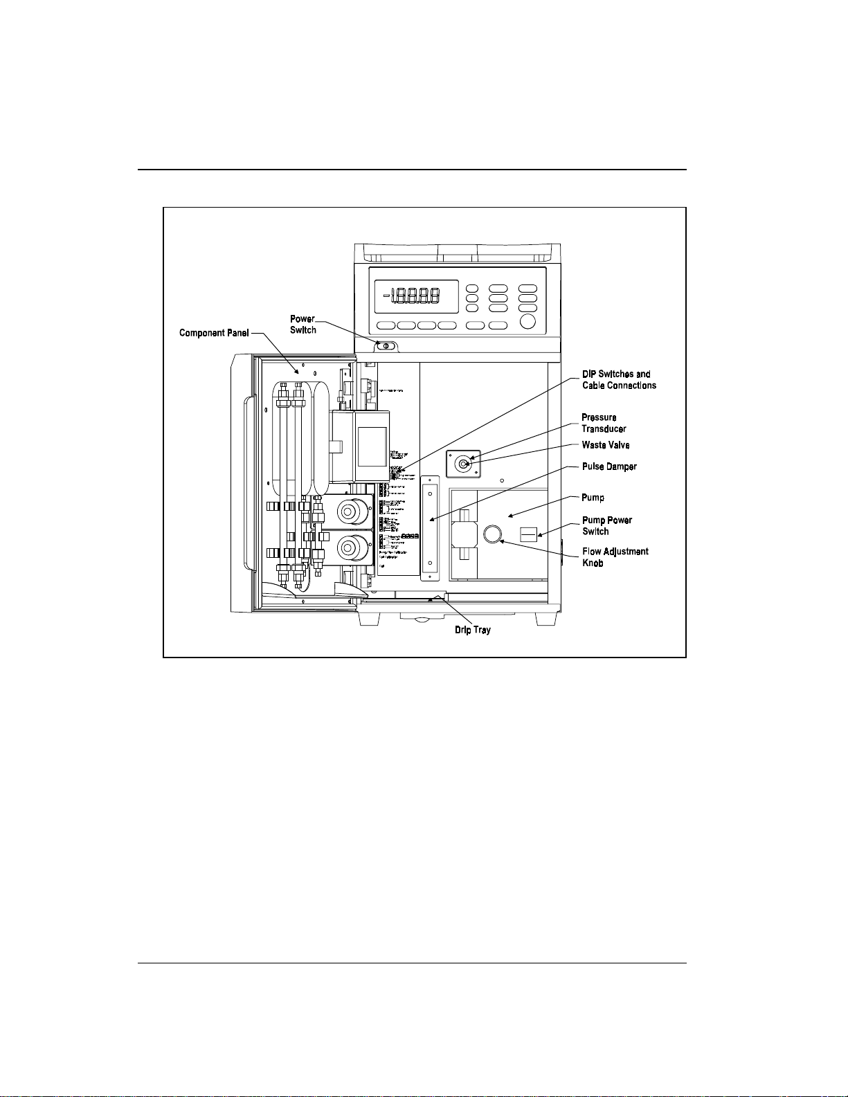
DX-120 Operator’s Manual
2-2
Figure 2-2. DX-120 Operating Features (Interior)
Doc. 031183-0 3 9/98
Page 17
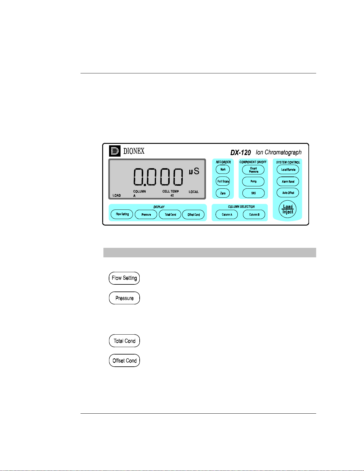
2.1 .1 Front Control Panel
The control panel liquid crystal d isplay (LCD) shows status
information and alarm conditions. Press a button in the group
labeled DISPLAY to determine the type of status information
shown. The remaining buttons control DX-120 operation.
Figure 2-3. DX-120 Control Panel
2 • Description
Button Function
DISPLAY
Doc. 031183-03 9/98
Displays the pump flow rate setting (0.5 to 4.5 mL/min).
Displays the pump pressure transducer reading (0 to
27.6 MPa or 0 to 4000 psi)
NOTE
MPa is the default pressure unit. For psi, set DIP
SW1-4 on. See Section B.10 for details.
Displays the total conductivity reading (0 to 999.9 µS).
Displays the offset conductivity reading (-999.9 to
999.9 µS). Offset conductivity is the total conductivity
minus the offset for the current run (see the description of
the Auto Offset button).
Table 2-1. Control Panel Button Functions
2-3
Page 18
DX-120 Operator’s Manual
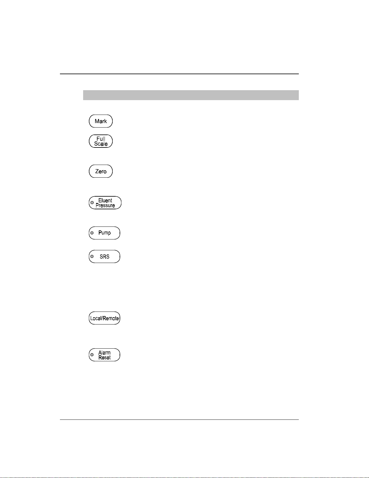
Button Function
RECORDER
Delivers a chart mark signal to the analog output. The mark
is 10% of the full-scale voltage.
Delivers a 100% signal to the analog output. Pressing the
button continuously keeps the output signal at full scale. The
default full-scale voltage is 1 V, but can be changed to 10 V
(SW4-4).
Reduces th e analog output si gnal to zero. Pres sing the
button continuously keeps the output signal at zero.
COMPONENT ON/OFF
Turns the gas pressure to the eluent reservoirs on and off.
When on, the LED on the button is illuminated. This button
is
disabled
Local/Remote below).
Turns the pump flow on and o ff. When on, the LED on the
button is illuminated. This button functions in Local or
Remote mode.
Turns the SRS power on and off, as well as the DS4
Detection Stabilizer, if installed. When on, the LED on the
button is illuminated. In the dual-column configuration, this
button controls the power to the SRS and DS4 of the
selected column set (see Section 2.2.1). This button is
disabled
Local/Remote below).
when the DX-120 is in Remote mode (see
when the DX-120 is in Remote mode (see
2-4
SYSTEM CONTROL
Toggles between Local and Remote control modes. Local is
control from the DX-120 control panel and Remote is
control from a PeakNet workstation via the DX-LAN. The
selected mode is shown in the lower right-hand corner of the
display.
A red LED on the left side of the button indicates an alarm
condition. The top line of the display in dicates the source of
the alarm: cabinet or cell leak, high or low pressure, or SRS.
Pressing the button clears the alarm. If the alarm condition
is still present, the alarm reappears after 15 seconds.
Table 2-1. Control Panel Button Functions (continued)
Doc. 031183-0 3 9/98
Page 19

Button Function
Offsets the background conductivity. After start-up, allow
the system to equilibrate. The display shows the background
conductivity (the eluent conductivity before sam ple
injection). Press Auto Offset to offset this background
reading and zero the chromatogram baseline.
Switches the injection valve between the Load and Inject
positions. The current position is shown in the lower
left-hand co rner of the dis play.
When switched from Load to Injec t, the DX-120 also:
- sends a chart mark signal to the analog output (SW4-7)
- performs an auto offset (SW3 -3)
- sends a TTL signal indicating that an injection has
occurred
After 1 minute, the valve automatically returns to the Load
position (SW1-1).
This button is
mode.
COLUMN SELECTION
The COLUMN SELECTION buttons are active in the
dual-column configuration only.
In column select mode, this button initiates the column
switching sequence from column set B to column set A (see
Section 2.2.1). In eluent select mode, this button switches to
eluent delivery from line A (see Section 2.2. 2).
In column select mode, this button initiates the column
switching sequence from column set A to column set B (see
Section 2.2.1). In eluent select mode, this button switches to
eluent delivery from line B (see Section 2.2.2).
disabled
2 • Description
when the DX-120 is in Remote
Doc. 031183-03 9/98
These buttons are
mode.
disabled
when the DX-120 is in Remote
Table 2-1. Control Panel Button Functions (continued)
2-5
Page 20

DX-120 Operator’s Manual
2.1.2 Pump
The pump is located on the rig ht side of the main
compartment (see Figure 2-2). The knob o n the front of the
pump adjusts the flow rate from 0.5 to 4.5 mL/min.
Eluent Save Mode
If the DX-120 is idle (i.e., no control panel buttons have been
pressed and no PeakNet commands have been received) for
90 minutes, the pump flow automatically decreases to 1/20 th
of its cur rent flow rate and the SRS cycles on and off. When
this occurs, the LEDs on the
Press any button to return to the last selected flow rate.
To turn off this feature, reset the Pump Time-out DIP switch
(SW1-2).
2.1 .3 Configuration DIP Switches
Pump
and
SRS
buttons flash.
The DIP switches on the left side of the main compartment
control system parameters. The factory-set defaults can be
changed to meet specific system and application requirements
(see Section B.10).
NOTE
In this manual, when a function is controlled by a DIP
switch setting, the switch and position numbers are shown
in parentheses. For example: (SW1-3, 4) indicates DIP
switch 1, positions 3 and 4.
2-6
Doc. 031183-0 3 9/98
Page 21

2.1.4 Eluent Reservoirs
Dionex strongly recommends degassing all elue nts and
storing them in reservoirs pressurized with helium. This helps
prevent bubbles (resulting from eluent outgassing) from
forming in the pump head and the detector cell. Degassed
eluents and pressu rized reservoirs are especially impo rtant
when combining aqueo us and non-aqueous components (e. g.,
water and methanol). With non-aqueous components, glass
reservoirs are recommended.
The single-column DX-120 in cludes one 2-liter plastic
reservoir (P/N 0441 29). The dual-colu mn DX-120 includes
two 2-liter plastic reservoirs.
The following additional reservoirs are available from Dionex:
•
1-liter plastic reservoir (P/N 044128)
•
1-liter glass reservoir with shatterproof plastic coating
(P/N 044126)
2 • Description
Doc. 031183-03 9/98
•
2-liter glass reservoir with shatterproof plastic coating
(P/N 044127)
The 2-liter plastic reservoir is not designed for vacuum
degassing. Do not use it for this purpose.
2-7
Page 22

DX-120 Operator’s Manual
2.1 .5 Component Panel
Chromatography components are mounted on the inside fron t
door. Figure 2-4 shows the single-column component panel
layout. Figure 2-5 shows the dual-column layout.
The DX-120 is equipped with a Rheodyne injection valve
(see Section 2.1.6). The following additional components
must be ordered separately:
•
Self-Regenerating Suppressor(s) (SRS): The SRS
neutralizes the eluent and enha nces analyte conductivity.
For a dual-column system, order two suppressors.
•
Column(s): One or two analytical columns and one or two
guard columns can be installed on colu mn clips. The clips
have larger clasps on one side for supporting 4 mm
columns and smaller clasps on the other side for 2 mm
columns.
•
Column switching valve: The column switching valve is
installed only in a dual-column system. Th e valve controls
liquid flow to the selected column (in column select
mode) or from the selected eluent (in eluent sele ct mode).
See Section 2.2 for details abou t dual-column systems.
2-8
•
Detector cell: Only one flow-through cell is required in
either the single- or the dual-column system. Two cell
models are available: a DX-120 standard cell (the
CDM-3) and a DX-120 high-performance cell with heater
(the DS4 Detection Stabilizer). The DS4 is recommended
for applications requiring enhanced thermal stability. See
sections 2.1.7 and 2.1.8 for details about the cells and the
DS4.
Doc. 031183-0 3 9/98
Page 23
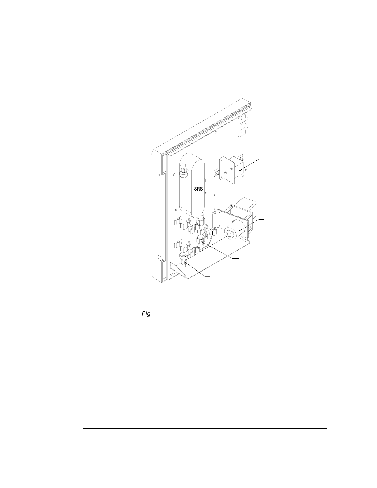
SRS
2 • Description
CDM-3 Cell
Injec tion Va lv e
Doc. 031183-03 9/98
Guard Column
Analytical Colum n
Figure 2-4. Single-Column Component Panel Layout
NOTE
A DS4 Detection Stabilizer can be installed instead of the CDM-3
cell.
2-9
Page 24
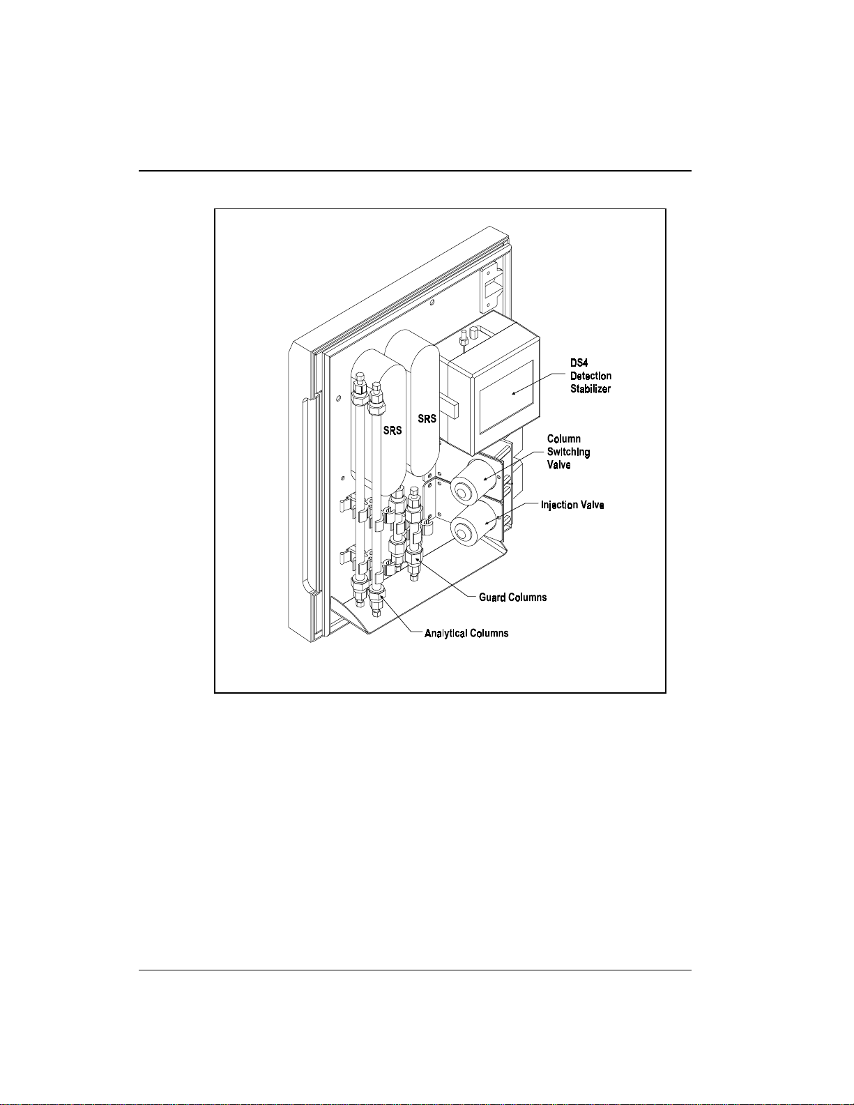
DX-120 Operator’s Manual
2-10
Figure 2-5. Dual-Column Component Panel Layout
NOTE
A CDM-3 cell can be installed instead of the DS4 Detection
Stabilizer.
Doc. 031183-0 3 9/98
Page 25
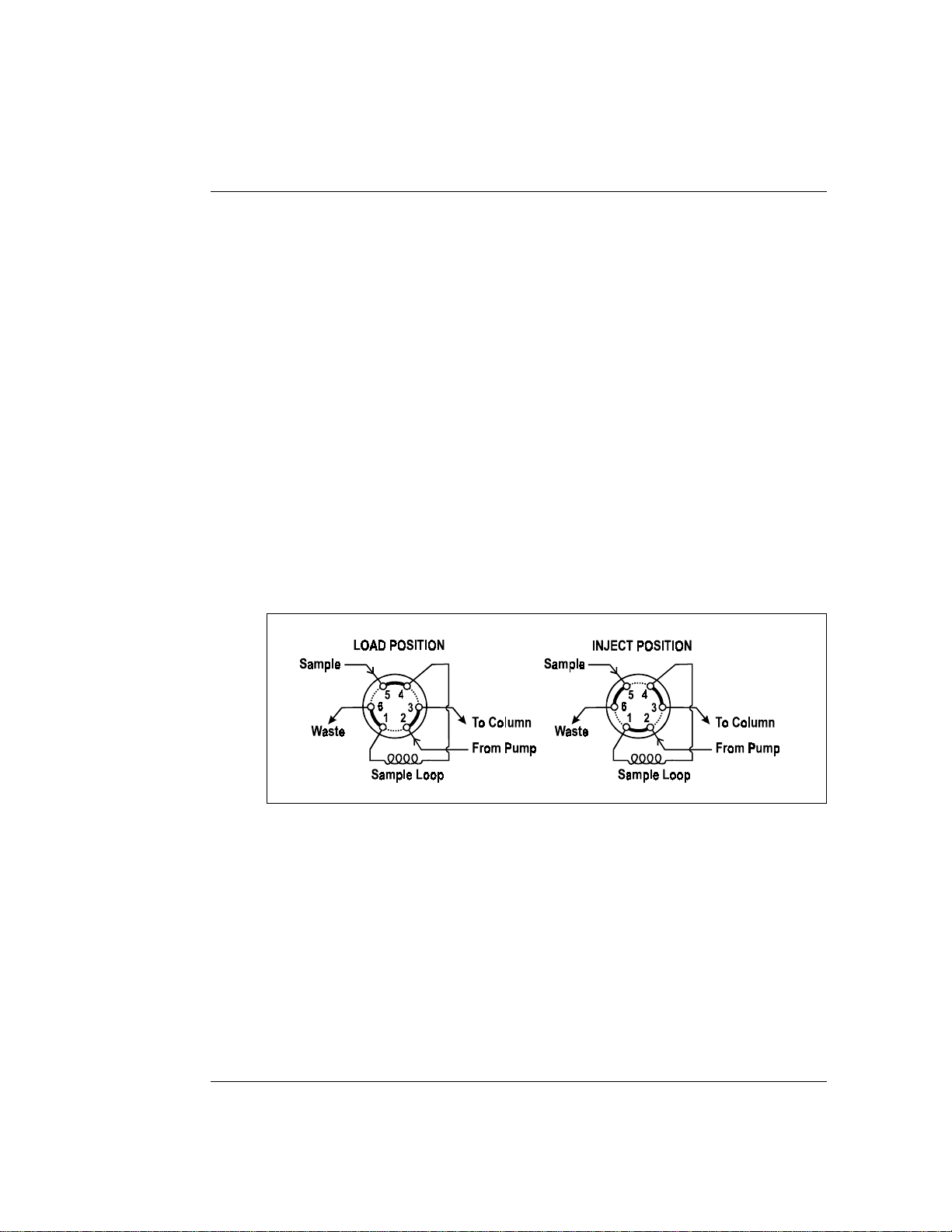
2.1 .6 Rheodyne Injection Va lve
The Rheodyne injection valve has two operating positions:
Load and Inject. In the Load position, sample is loaded into
the sample loop, where it is held until injection. In the Inject
position, sample is swept to the column for analysis. Eluent
flows through one of two paths, depending on the valve
position:
•
In the Load position, eluent flows from the pump, through
the valve, and to the column, bypassing the sample loo p.
Sample flows from the syringe or autosampler line,
through the valve, and into the sample loop; excess
sample flows out to waste.
•
In the Inject position, eluent flows from the pump,
through the sample loop, and on to the column, carrying
the contents of the sample loop with it.
2 • Description
Doc. 031183-03 9/98
Figure 2-6. Rheodyne Injection Valve Flow Schematics
2-11
Page 26

DX-120 Operator’s Manual
2.1.7 Detector Cells
The DX-120 accommodates two detector cell models. The
DX-120 standard cell (CDM-3; P/N 050776) is used for
applications that do not require th e enhanced baseline
stability gained through thermal stabilization. For increased
thermal stabilization in high-sensitivity applications, use a
DX-120 high-performance cell with heater (DS4 Detection
Stabilizer; P/N 050218).
If you change the cell model, the Cell Type DIP switches
(SW4-1, 2) must be reset to sel ect the new cell type.
Detector Cell Features
•
Both cells are flow-through conductivity cells with
polymeric bodies. Two 316 stainless steel electrodes are
permanently sealed into the cell bodies.
NOTE
•
A sensor (thermistor) located slightly downstream from
the electrodes senses the temperature of the liquid as it
exits the cell. The measured value is used for temperature
compensation.
•
The active volume is nominally 1.25 µL for the CDM-3
cell and 1.0 µL for the DX -120 high-perfo rmance cell.
•
The detector cell constant for both cells has a nominal
value of 160 cm
-1
.
The advanced geometry of the cells provide several benefits:
•
Excellent accuracy and linearity over a broad working
range
•
Efficient sweepout and low volume for low dispersion
•
Reduced sensitivity to electrode surface conditions
•
Low electrode mass
•
Effective temperature comp ensation
2-12
Doc. 031183-0 3 9/98
Page 27

2 • Description
Temperature Control and Compensation
Temperature directly affects the conductivity of a solution.
For example, laboratory heating and air conditioning systems
can cause a regular slow cycling in the baseline. This, in turn ,
can affect the reproducibility of an analysis. The higher the
conductivity, the more pronounced the effect.
In ion chromatography, suppressing eluent conductivity
minimizes the effect of temperature variation. Temperature
compensation further improves baseline stability. When the
conductivity cell is housed in a DS4 Detection Stabilizer, the
heater enhances the ability of these techniques to reduce
temperature effects on conductivity.
Temperature compensation also ensures that there is no major
change in the baseline or peak heights, should it be necessary
to change the DS4 operating set point. Readings will be
normalized to 25 °C.
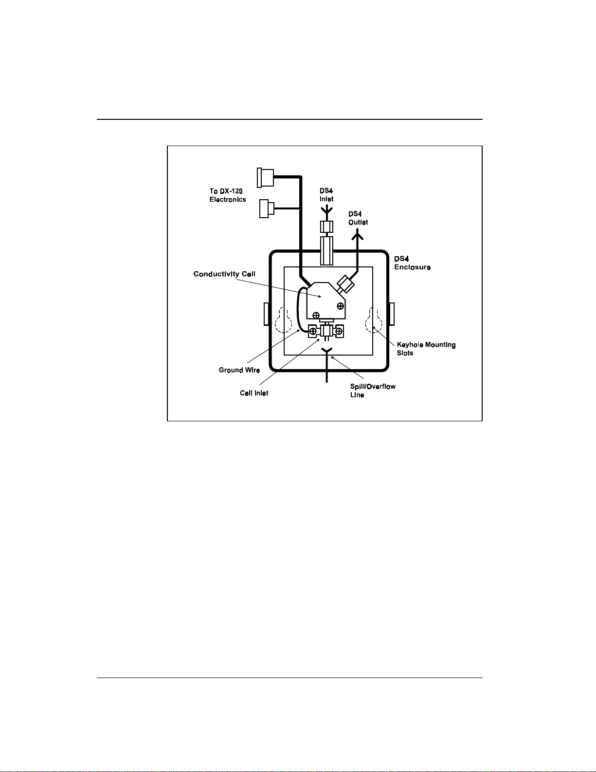
2.1.8 DS4 Detection Stabilizer
Doc. 031183-03 9/98
The DS4 is a temperature-controlled chamber consisting of a
cast aluminum base and cover enclosed in insulating foam.
The chamber houses both the cond uctivity cell and the eluent
heat exchanger. Figure 2-7 identifies the major components of
the DS4.
The DS4 provides the following benefits:
•
Conductivity measurements nearly impervious to
laboratory temperature variation
•
Very low disp ersion in the eluent heat exchan ger
•
Excellent peak height reproducibility
•
User-selected temperature set point
2-13
Page 28
DX-120 Operator’s Manual
2-14
Figure 2-7. DS4 Detection Stabilizer Features
Power input to a pair of transistors on opposite sid es of the
DS4 heats it to a user-selected temperature from 30 °C to
45 °C (SW3-4, 5, 6, 7). A sensor near the heat exchang er
outlet senses the eluent temperature. The DX-120 circuitry
compares this temperature with the selected temperature and
adjusts the heat input in real time to hold the temperature
within a few millidegrees.
The DS4 is sealed with an O-ring to trap eluent that may leak
from the cell. If 5 mL of liquid accumulates, a thermistor
sensor signals a leak to the CPU. Any additional leakage will
be discharged via the spill/overflow line. A second thermistor,
above the discharge level, acts as a temperature reference for
the leak sensor.
Doc. 031183-0 3 9/98
Page 29

2.2 Dual-Column Configuration Features
The dual-column configuration has two operating modes:
Column select mode allows switching of flow from one column
•
set to the other.
Eluent select mode allows switching of flow from one eluent to
•
the other (the column set is not switched).
The Column Select DIP switch (SW3-1) selects the mode:
on=column; off=eluent.
The dual-column system option adds the f ollowing features:
2 • Description
Column A
The
•
and
Column B
buttons on the front contro l panel
are enabled .
An eluent selection valve selects which eluent reservoir is used.
•
A column switching valve directs flow to the selected column set
•
(column select mode only).
Doc. 031183-03 9/98
2-15
Page 30

DX-120 Operator’s Manual
2.2 .1 Column Select Mode
In column select mode, you can switc h the flow path from
one column set to the other by pressing
B
or by sending a command from PeakNet.
Figure 2-8 illustrates the sequence of events when you switch
from column set A to column set B.
Column A
or
Column
2-16
Figure 2-8. Column Selection Sequence
Doc. 031183-0 3 9/98
Page 31

2 • Description
1. In Step 1, eluent A is flowing to column set A.
2. In Step 2, the following occurs:
A command is received to switch to column B.
•
The eluent selection valve switches and eluent B
•
begins flowing to the injection valve.
The display flashes
•
The injection valve switches to the Inject position and
•
RINSE
.
the previous eluent is cleared from the sample loop.
A short delay occurs before th e column switching
•
valve switches to the new position. This allows eluent
A to continue through to column set A. The duration of
the delay depends on the current flow rate. Lower flow
rates require a longer rinse time.
3. In Step 3, the following occurs:
When eluent A has been cleared from the lines, the
•
column switching valve switches and flow proceeds to
the selected column set.
The injection valve returns to the Load position.
•
RINSE
•
The
indicator stops flash ing and the display
shows the new column selection. The system is now
ready for use.
NOTE
There is a small amount of eluent carryover when switching
column sets. For this reason, ignore the first injection run after
switching columns.
Doc. 031183-03 9/98
2-17
Page 32

DX-120 Operator’s Manual
2.2.2 Eluent Select Mode
In eluent select mo de, pressing
Column A
Column B
or
, or
sending an eluent switching command from PeakNet,
switches the eluent selection valve to the new position.
In this mode, the column sw itching valve is disabled. The
selected column set remains at what it was when the DX-120
was switched to eluent select mode. The LED on the button
for the selected column set is always illuminated and the
display indicates the selected eluent (see the example in
Figure 2-9).
2-18
Figure 2-9. Display During Eluent Select Mode
Doc. 031183-0 3 9/98
Page 33

2.3 Fluid Schematics
0.03 - 0.07 MPa
(5 - 10 psi)
Figure 2-10 shows the flow path through a single-column DX-1 20
Ion Chromatograph.
2 • Description
Doc. 031183-03 9/98
Figure 2-10. DX-120 Flow Schematic: Single-Column
2-19
Page 34

0.03 - 0.07 MPa
(5 - 10 psi)
DX-120 Operator’s Manual
Figure 2-11 shows the flow path through a dual-column DX-1 20 Ion
Chromatograph in column select mode.
2-20
Figure 2-11. DX-120 Flow Schematic: Dual-Column System
Column Select Mode
Doc. 031183-0 3 9/98
Page 35

0.03 - 0.07 MPa
(5 - 10 psi)
2 • Description
Figure 2-11 shows the flow path through a dual-column DX-1 20 Ion
Chromatograph in eluent select mode.
Doc. 031183-03 9/98
Figure 2-12. DX-120 Flow Schematic: Dual-Column System
Eluent Select Mode (Column Set A Active)
2-21
Page 36

DX-120 Operator’s Manual
2.4 Control Modes
The DX-120 has two control modes: Local and Remote. Select Local
for control from the DX-120 front control panel and select Remote
for control from a PeakNet workstation.
To change the mode, press
Local/Remote
. The selected mode is
shown in the lower right-hand corner of the display.
2.4 .1 Local Mode
When the DX-120 is powered up, it defaults to L ocal mode.
Local mode allows two types of operating commands:
•
Direct input from the DX-120 front control panel buttons
•
TTL inputs from a remote controller, such as an integrator
or recorder
2.4 .2 Remote Mode
In Remote mode, the DX-120 accepts operating commands
from PeakNet software via the DX-LAN interface. Sending
an operating command from PeakNet automatically selects
Remote mode, if it was not already selected.
Several DX-120 control panel buttons are disabled in Remote
mode, as indicated in the following table.
Disabled Buttons in Remote Mode Active Buttons in Remote Mode
2-22
Load/Inject
Eluent Pressure
(on/off)
SRS
Column A
and
(on/off)
Column B
DISPLAY
RECORDER
Pump
Local/Remot e
Alarm Reset
Auto Offset
group (all)
(on/off)
group (all)
Doc. 031183-0 3 9/98
Page 37

2.5 TTL Control
The TTL input connectors on the DX-120 rear panel allow limited
remote control of the DX-120. With TTL input, a controlling d evice
(such as an integrator or automated sampler) sends TTL signals to
the DX-120. TTL input signals can be use d to:
Toggle the position of the injection valve and start a PeakNet run
•
(these two functions are controlled simu ltaneously)
Offset the background conductivity
•
Change th e recorder ran ge by 10x
•
Turn the pump flow on and off
•
TTL control is available when the DX-120 is in either Local or
Remote mode.
Refer to Section B.7 for TTL connection instru ctions.
2 • Description
2.5 .1 Injection Valve/Remote Start Control
A TTL output signal from another device, such as an
automated sampler, can switch the injection valve to the
Inject position. The same TTL input signal is also used to
start a PeakNet run when the DX-120 is connected to a
PeakNet workstation.
NOTE
If required for an application, disable the TTL injection
valve control and use only the remote start function. See
Section B.8. 3 for instructions.
2.5 .2 Recorder Range Control
The default full- scale recorder output signal range is
1000 µS. This is set by the Range DIP switch (SW4-3).
Sending a 10X Range TTL input signal when the recorder
output is at 100 µS changes the fu ll-scale recorder range to
1000 µS. The range will remain at 1000 µS as long as the
input signal is being sent from the controlling device.
Doc. 031183-03 9/98
2-23
Page 38

DX-120 Operator’s Manual
If the Range DIP switch is set to 1000 µS, sending the 10X
Range TTL input sign al will have no effect.
The table below summarizes the relationship between the 10X
Range TTL input and th e Range DIP switch.
Range DIP Switch
(SW4-3) Setting
1000 µS*
1000 µS
100 µS
100 µS
*Default settings
The Range DIP switch setting and the 10X Range TTL
input are only for recorder output control; they do not
affect either the conductivity readings shown on the
control panel display or the PeakNet data.
10X Range TT L Input
Status
1X*
10X
1X
10X
NOTE
Signal Output
1000 µS*
1000 µS
100 µS
1000 µS
2-24
Doc. 031183-0 3 9/98
Page 39

3 • Operation and Maintenance
3.1 Preparing Eluents
3.1 .1 Degassing Eluents
Dionex strongly recommends degassing all eluents an d
storing them in reservoirs pressurized with filtered inert gas
(see Section 3.1.3). This helps prevent bubbles (resulting
from eluent outgassing) from forming in th e pump and the
detector cell. Degassed eluents and pressu rized reservoirs are
especially important when combining aqueous and
nonaqueous components (for example, water and methanol).
Several degassing procedures can be used, includ ing vacuum
degassing, sparging with helium, or sonication without
vacuum. Follow the steps below for vacuum degassing:
1. Prepare the eluent required for the application. Pour it
into a clean vacuum flask and attach the flask to a
vacuum pump or water aspirator.
Doc. 031183-03 9/98
2. Vacuum degas the eluent for 5 min utes while agitating the
solution by shaking or sonication.
When using nonaqueous components, do not degas eluents
for longer than 5 minutes; volatile compounds may be lost.
3. Remove the flask from the vacuum. Do not allow water
to flow from the a spirator back into the flask.
4. Pour the degassed eluent into a pressurizable reservoir. Be
careful not to shake the eluent.
5. Install end-line filters and pressurize the reservoirs (see
Sections 3.1.2 and 3.1.3).
3-1
Page 40

DX-120 Operator’s Manual
3.1 .2 Filtering Eluents
Always filter eluents before operation to remove small
particulates that may contaminate the pump check valves and
cause erratic flow rates or loss of prime. End-line filters
(P/N 045987) are sup plied in the pressurizable reservoir ship
kits for this purpose.
Install an end-line filter on the end of the eluent line inside
the reservoir. To pr event air from being drawn through th e
lines, make sure that the end of the filter reaches the bottom
of the eluent reservoir.
3.1 .3 Pressurizing Eluent Reservoirs
Pressurize eluent reservoirs with filtered inert gas (preferably
helium). Refer to the Pressurizable Reservoir Installation
Instructions for details.
1. Verify that the gas supply is connected to the HELIUM
INPUT connector on the rear panel and is regulated to
between 0.14 and 0.69 MPa (20 and 100 psi).
3-2
2. Press
Eluent Pressure
to turn on the gas pressure to the
eluent reservoir(s). A regulator inside the DX-120
regulates the pressure to between 0.03 and 0 .07 MPa (5 to
10 psi).
Never pressurize the reservoirs above 0.07 MPa (10 psi). If
using glass reservoirs, inspect them periodically for
scratches or cracks.
Doc. 031183-0 3 9/98
Page 41

3.2 Preparing Samples
3.2 .1 Collecting and Storing
Collect samples in high density polyethylene con tainers that
have been thoroughly cleaned with deionized water. Do not
clean containers with strong acids or detergents because they
will leave traces of ions on the container walls. These ions
may interfere with analysis.
If samples will not be analyzed on the day they are collected,
filter them through clean 0.45 µm filters immediately after
collection; otherwise, bacteria in the samples may cause the
ionic concentrations to change over time. Refrigerating the
samples at 4 °C will minimize, but not eliminate, bacterial
grow th .
Analyze samples containing nitrite or sulfite as soon as
possible. Nitrite oxidizes to nitrate, and sulfite to sulfate, thus
increasing the measured concentrations of these ions in the
sample. In general, samples that do not contain nitrite or
sulfite can be refrigerated for at least one week with no
significant changes in anion concentrations.
3 • Operation and Maintenance
3.2.2 Pretreating
Doc. 031183-03 9/98
Analyze rain water, drinking water, and air particulate leach
solutions directly with no sample preparation (other than
possibly filtering and diluting).
Filter groundwater and wastewater samples through 0.45 µm
filters before injection, unless samples were filtered after
collection.
Before injection, pretreat samples that may contain high
concentrations of interfering substances by putting them
through Dionex OnG uard cartridges. Refer to the
Installation and Troubleshooting Guide for O nGuard
Cartridges (Document No. 0329 43) for instructions.
3-3
Page 42

DX-120 Operator’s Manual
3.2.3 Diluting
Because the concentrations of ionic species in d ifferent
samples can vary widely from sample to sample, no single
dilution factor can be recommended for all samples of one
type. In some cases (for example, many water samples)
concentrations are so low that dilution is not necessary.
Use deionized water or eluent to dilute the sample. When
using carbonate/b icarbonate eluents, d iluting with eluent
minimizes the effect of the water dip at the beginning of the
chromatogram. If you dilute the sample with eluent, also use
eluent to prepare the calibration blank and standard s. This is
most important for fluoride and chloride, which elute near the
water dip.
To improve the accuracy of early eluting peak determinations,
such as fluoride, at concentrations below 50 ppb, dilute
standards in eluent or spike the samples with concentrated
eluent to minimize the water dip. For example, spike a 100
mL sample with 1.0 mL of a 1 00 X eluent concentrate.
3-4
Doc. 031183-0 3 9/98
Page 43

3.3 Operating
3.3.1 Starting Up
1. Press the power switch below the DX-120 front control
panel (see Figure 2-2) to turn on the system power.
Microprocessor code revision levels are displayed briefly
on the screen, and then the offset conductivity reading is
displayed.
These are the conditions at power-up:
•
•
•
•
3 • Operation and Maintenance
The DX-120 is in Local mode.
The eluent pressure, pump, and SRS are off.
The DS4 Detection Stabilizer (if installed) is on.
The injection and column selection valves are in their
last selected positions.
The offset value is reset to zero.
•
2. Press the power switch on the front o f the pump (see
Figure 2-2) to turn on the pump p ower.
3. Press
4. Press
5. Press
Eluent Pressure
Pump
to turn on the pump flow.
SRS
to turn on the SRS power. The screen briefly
to pressurize the eluent rese rvoirs.
displays the SRS current setting in mA.
6. Press
Flow Rate
and verify that the pump flow rate is
correct. If necessary, pull out the kn ob on the front of the
pump and turn it right or left to increase or decrease the
flow rate. When the correct rate is displayed, push in the
knob.
7. Press
Offset Cond
to display the offset conductivity
reading.
Doc. 031183-03 9/98
3-5
Page 44

DX-120 Operator’s Manual
8. Allow the system to equilibrate for 15 to 20 minutes. The
screen displays the background conductivity (the
conductivity of the eluent before injecting sample). Press
Auto Offset
If a DS4 is installed, system equilibration must also
include the time required for the DS4 to reach operating
temperature. The DS4 warms up at about 1 °C/minute
above ambient. Baseline conductivity should stabilize
once the DS4 reaches the selected temperature. The DS4
temperature status appears at the bottom of the display:
to offset the backgro und and zero the read ing.
LO CELL TEMP
•
appears and the temperature set point
flashes when the DS4 is below temperature.
CELL TEMP
•
appears and the set point stops flashin g
when the DS4 has reached operating temperature.
CELL TEMP HI
•
appears and the temperature set point
flashes when the DS 4 is above operating temperatu re.
Figure 3-1 shows the display after all start-up steps are
complete and the DX-120 is ready for a sample injection.
Figure 3-1. Display after Start-Up Completed
3-6
NOTE
If the DX-120 receives no input for 90 minutes, the
pump flow is reduced to 1/20th of its current rate and
the SRS cycles on and off (SW1-2). The LEDs on the
Pump
and SRS buttons flash when this occurs. Press
any button to return to the previous flow rate.
Doc. 031183-0 3 9/98
Page 45

3.3 .2 Injecting the Sample
This section describes how to inject sample when the DX-120
is in Local control. PeakNet software can also be used to
switch the injection valve position.
Using a Syri nge
3 • Operation and Maintenance
1. Verify that
the display. If necessary, press
LOCAL
is shown at the lower-right corner of
Local/Remote
to toggle to
Local mode.
2. Verify that
display. If necessary, press
LOAD
is shown at the lower-left corner of the
Inject/Load
to switch the
injection valve to the Load position.
3. Fill the syringe with a calibration standard or sample.
4. Insert the syringe into the p ort on the front of the DX-120
(see Figure 2-2).
5. Overfill the sample loop with several sample loop
volumes. Excess sample will exit through the waste line.
6. Leave the syringe in the port.
7. Press
Using an Autosampler
Inject/Load
to switch the injection valve to Inject.
The autosampler output line connects to port 5 on the
injection valve. See Section B.8 for installation instructions.
Doc. 031183-03 9/98
1. Verify that
the display. If necessary, press
LOCAL
is shown at the lower-right corner of
Local/Remote
to toggle to
Local mode.
2. Verify that
display. If necessary, press
LOAD
is shown at the lower-left corner of the
Inject/Load
to switch the
injection valve to the Load position.
3. Follow the instructions included with the autosampler to
load the injection valve loop.
3-7
Page 46

DX-120 Operator’s Manual
4. Press
Injection Events
Inject/Load
to switch the injection valve to Inject.
By default, the following events occur after injection:
•
An auto offset occurs (SW 3-3), which include s two steps:
- The analog output signal is set to zero.
- The background conductivity is offset from the total,
thereby zeroing the baseline conductivity value. This is
the same function as pressing
Auto Offset
on the front
panel.
•
An inject mark is sent out on the analog output (SW4-7).
•
The Inject TTL output sends o ut a pulse indicating that
injection occurred.
•
After 1 minute, the injection valve returns to the Load
position (SW1-1).
Injection Duration
To ensure complete injection of the sample, at least 10
sample volumes must be pumped through the loop before the
valve is switched back to the Load position. For most
applications, automatically returning to Load after 1 minute is
sufficient. Here are the maximum loop sizes for a one-minute
injection at 1 mL/min and 2 mL/min:
3-8
•
At 1 mL/min, use a loop of 100 µL or less.
(1000 µL/min)(1 sample vol/100 µL)=10 sample vol/min
•
At 2 mL/min, use a loop of 200 µL or less.
(2000 µL/min)(1 sample vol/200 µL)=10 sample vol/min
If your flow rate/loop combination requires more time,
disable the automatic return (SW1-1) (see Section B. 10).
Doc. 031183-0 3 9/98
Page 47

3 • Operation and Maintenance
3.4 Using an Integrator
You can connect an integrator, such as the Dionex 4400 or 4600
Integrator, to the DX-120 and use a DIALOG or BASIC program to
automate analyses. If you also connect an autosampler, sample
loading can also be controlled. See Appendix C for integrator
programming examples.
3.5 Running under PeakNet Control
When the DX-120 is connected to a PeakNet workstation via the
DX-LAN interface, PeakNet software (Release 4.30 or higher) can
monitor DX-120 status and control the following functions:
Select the position of the injection and colu mn switching valves
•
Turn the pump flow, SRS power, and eluent pressure on and off
•
Perform an auto offset
•
Select the pressure units displayed on the screen (MPa or psi)
•
Control TTL1 and TTL2 output signals
•
Control the auxiliary AC outlet (PeakNet control only)
•
For more information, refe r to the PeakNet So ftware User’s G uide.
Doc. 031183-03 9/98
3-9
Page 48

DX-120 Operator’s Manual
3.6 Optimizing Temperature Compensation
The DX-120 built-in temperature compensation stabilizes
conductivity readings by correcting for changes in ambient
temperature that occur during a run. For more information about
temperature control and compensation, see Section 2.1.7.
3.6.1 With a DS4
Housing the cell in a DS4 Detection Stabilizer ensures that
there is no more than a minor temperature variation in liquid
reaching the cell. Thus, the temperature compensation DIP
switch setting can remain at the default of 1.7% per ºC.
Many users are able to keep th eir systems at a single
operating temperature. For optimal accuracy, calibrate the cell
at this temperature. If you later reset the temperature, th e
DX-120 temperature compensation will normalize
conductivity measurements to 25 °C (77 °F) to p revent a
major upset in system calibration. If you change the DS4 set
point, recalibrate the cell.
3-10
If temperature-induced baseline cycling occurs, it is probably
caused by another component of the chromatography system.
If the variation increases as the eluent reservoir empties,
move the reservoir to a more temperature-stable environment
and/or wrap the reservoir in thermal insulation.
3.6.2 With a CDM-3 Cell
When the CDM-3 cell is installed, conductivity drifts up and
down with fluctuations in laboratory temperature. This is
especially noticeable in laboratories with very high air
turnover rates or no air conditioning. Selecting the proper
temperature compensation factor will minimize the effect of
temperature fluctuations.
The temperature compensation setting is selected with a DIP
switch (SW5-3, 4, 5). Three settings are available: 1.5%,
1.7%, and 1.9%. Start with the default setting of 1.7%. If a
Doc. 031183-0 3 9/98
Page 49

3 • Operation and Maintenance
sinusoidal baseline variation of the same period as the
laboratory cooling or heating occurs, increase or decrease the
temperature compensation setting. If the baseline variation
still occurs, try the other setting.
3.7 Maintenance
This section describes routine maintenance procedures that users can
perform. All other maintenance procedures must be performed by
Dionex personnel.
Daily
Check the interior of the main compartment for leaks or spills.
•
Wipe up spills. Isolate and repair leaks (see Section 4.3). Rinse
off any dried eluent or reagent with deionized water.
Check the waste container daily and empty when needed.
•
Weekly
Once a week, chec k air lines for crimping or discoloration.
•
Relocate any pinched lines. Replace damaged lines.
Check the junction between the p ump head and the metal pump
•
casting for evidence of liquid leaks. Normal friction and wear
may gradually result in small liquid leaks aroun d the piston seal.
If unchecked, these leaks can gradually contaminate the piston
housing, causing the pump to operate poorly. If leaks occur,
replace the piston sea ls (see Section 5.9).
Doc. 031183-03 9/98
3-11
Page 50

DX-120 Operator’s Manual
3-12
Doc. 031183-0 3 9/98
Page 51

4 • Troubleshooting
This chapter is a guide to troubleshooting problems that may occur
while operating the DX-120. If an alarm sounds, check Section 4.1
for possible cause s. If an error code is display ed, check Section 4.2
for possible causes. To resolve other problems, turn to the section
that best describes the operating problem.
If you are unable to eliminate a problem, contact Dionex for help. In
the U.S., call Dionex Technical Support at 1-800-346-6390. Outside
the U.S., call the nearest Dionex office.
4.1 Alarms
Three events signal an alarm condition: a tone sounds, the LED on
Alarm Reset
the
and the ala rm’s source. To clear the alarm, pre ss
alarm condition still exists, the alarm will reappear after 15 seconds.
The alarm tone can be disabled with a DIP switch (SW3-2).
LEAK ALARM
•
button blinks, and the display indicates ALARM
Alarm Reset
. If the
There is liquid in the drip tray. Wipe up spills in the tray and
check for leaks (see Section 4.3).
CELL LEAK ALARM
•
There is a leak in the DS4 (see “Leaking DS4” in Section 4.3).
LOW PRESSURE ALARM
•
The system pressure is less than or equal to the low pressure
limit of 1.7 MPa (250 psi). T his condition automatically turns off
the pump and SRS. Th is alarm can be turned off with a DIP
switch (SW1-8 ).
1. Make sure the eluent reservoirs are full.
2. Check for liquid leaks (see Section 4.3).
Doc. 031183-03 9/98
4-1
Page 52

DX-120 Operator’s Manual
3. Make sure the pressu re transducer waste valve is closed. To
close the valve, turn the knob clockwise, just until tight. Do
not overtighten! Overtightening may damage the valve
and the pressure transducer housing.
4. Restart the pump.
5. Prime the pump (see Section B.5.1).
HIGH PRESSURE ALARM
•
The system pressure is greater than or equal to th e high pressure
limit selected (SW1-5, 6, 7). This condition auto matically turns
off the pump and SRS.
1. Make sure the selected flow rate is not too high.
2. Check for blockages in the liquid line from the pump
pressure transduc er to the waste cont ainer.
3. Make sure the columns are not the so urce of the high
pressure.
4-2
4. Set the high pressure limit to 3.4 MPa (500 psi) above the
normal system operating pressure.
5. Restart the pump.
SRS ALARM
•
The SRS has exceed ed the accepted curr ent/voltage range.
1. The SRS may be dry. Make sure the eluent reservoir is filled
and sufficiently pressurized. Check all liquid lines and valves
for leaks, crimping, or blockage.
2. Make sure the cable connecting the SRS to the DX-120
electronics card is connected (see Figure B-10).
3. Refer to the SRS manual for more trou bleshooting
information.
Doc. 031183-0 3 9/98
Page 53

4.2 Error Codes
When an error occurs, an error code number displays in the middle
of the screen. The error code remains for several seconds, and th en
the display returns to normal.
E000
•
Cause: No Moduleware is installed. Moduleware is the DX-120
instrument control microprocessor code.
Action: Download a new copy of the Moduleware, if the system
includes Pe akNet software, o r contact Dionex f or assistance.
E001
•
4 • Troubleshooting
Cause: The
Column B
button was pressed, although the system is
configured for a single column.
Action: If it is a dual-column system, verify that the Column
Configuration DIP switch (SW1-3) is set to dual-column.
E002
•
Cause: Two or more conflicting DIP switch settings.
Action: Reset the DIP switches (see Section B.10).
E003
•
Cause: More than one high-pressure alarm setting is selected.
The pump and SRS will turn off when this error occurs.
Action: Check the high-pressure alarm setting (SW1-5 , 6, 7).
One switch position must be on and the other two off.
E004
•
Cause: During the rinse portion of the column switching
sequence, a command to switch columns was received from the
Column A
Column B
or
button, or from PeakNet.
Action: The DX-1 20 cannot begin another colu mn switching
sequence during the rinse cycle. Wait until the column switching
sequence is completed.
Doc. 031183-03 9/98
4-3
Page 54

DX-120 Operator’s Manual
E005
•
Cause: A command to switch columns was received from either
Column A
the
Column B
or
pump was off or the flow rate was very low. The rinse cycle step
of the column switching sequence requires an adequate flow rate
to flush the previous eluent from the system before switching.
Action: Turn on the pump or increase the flow rate.
E006
•
Cause: The SRS will not turn o n. Either the pump is not on or
the suppressor is disconnected.
Action: Turn on the pump. Make sure the cable connecting the
SRS to the DX-120 electronics card is connected (see
Figure B-10).
4.3 Liquid Leaks
button, or from PeakNet, while the
Leaking fitting
•
Locate the source of the leak. Tighten or, if necessary, replace
the liquid line connection (see Section 5.1). Refer to Installation
of Dionex Ferrule Fittings for tightening requirements.
Broken liquid line
•
Replace the line and fittings (see Section 5.1).
Blocked or improperly installed waste line
•
Make sure the waste lines are not crimped or otherwise blo cked.
Also make sure waste lines are not elevated at any point after
they exit the DX-120.
Loose pump check valve housing
•
Make sure the check valves are firmly seated in the pump head.
If they are not, tighten them carefully with an open end wrench
just until the leak stops.
4-4
Doc. 031183-0 3 9/98
Page 55

4 • Troubleshooting
Damaged pump piston seal
•
1. Replace the piston seal (see Section 5.9).
2. If the prob lem persists, replace the p iston (see Section 5.10 ).
Pump head not tigh t against casting
•
Carefully tighten the pump head mounting nuts just until the leak
stops. DO NOT OVERTIGHTEN!
Leaking pressure transducer
•
Make sure the liquid line connections into the transducer are
tight. Refer to Installa tion of Dionex Ferrule Fittings for
tightening requirements. Replace any damaged fittings.
Make sure the waste valve is closed. To close the valve, turn the
knob clockwise, just until tight. DO NOT OVERTIGHTEN!
Overtightening may damage the valve and the pressure
transducer housing.
Inspect the pressure transducer. If the waste valve is the source
of the leak, repla ce the waste valve O-ring (see Section 5. 11). If
the leak is from the rear of the transdu cer, contact Dionex for
assistance.
Leaking SRS
•
See the SRS manual f or troubleshooting proc edures.
Leaking injection valve or column switching valve
•
Liquid leaks from behind the valve stator may indicate a
scratched rotor seal. Contact Dionex for assistance.
Doc. 031183-03 9/98
4-5
Page 56

DX-120 Operator’s Manual
Leaking DS4
•
Check the waste lines for blockage; trapped particles can plug
the lines and cause a restriction and/or leak. If necessary, clear
the waste lines by reversing the direction of flow.
Make sure the plumbing downstream from the DS4 is clear; a
blockage may overpressurize the DS4, causing it to leak.
Make sure the downstream backpressure coils are appropriate for
the operating flow rate (see Section B.6.1).
Follow the steps below to disassemble the DS4 and inspect it for
the source of the leak.
1. Turn off the DX-120 power.
2. Disconnect the DS4 cables.
3. Disconnect the DS4 inlet and outlet lines. Do not misplace
the ferrule fittings at the end of the tubing (see Figure 4-1).
4. Remove the DS4 by lifting it upward and th en pulling it
away from its mounting location. Place the DS4 o n the
workbench.
5. Open both latches on the DS4 and carefully lift off the top
half of the cover, along with its insulating foam insert,
exposing an aluminum box (see Figure 4-1).
6. Remove the box from the bottom half of the cover.
7. Remove the four Phillips screws securing the top of the box
to its bottom plate. Carefully separate the two parts, exposing
the cell (see Figure 4-2). Lay the top aside, being careful not
to pull or stress the group of wires that con nect the two parts.
8. Check the inlet and outlet cell fittings for leaks. Tighten or
replace if necessar y.
9. Dry the DS4, test fo r leaks, and reassemble. Make sure the
foam insert is adjusted evenly around the various DS4
components, with no pinching or folding. Befo re latching the
cover, make sure the top and bottom inserts meet on all sides.
4-6
Doc. 031183-0 3 9/98
Page 57

4 • Troubleshooting
Doc. 031183-03 9/98
Figure 4-1. DS4 Exploded View
Figure 4-2. DS4 Interior Components
4-7
Page 58

DX-120 Operator’s Manual
Liquid seeping from around cell cables
•
The cell has an internal leak and must be replaced. Contact
Dionex for assistance.
4.4 Pump Difficult to Prime
Empty reservoir and/or no eluent connected
•
Connect the pump inlet line to the eluent reservoir. Fill the
reservoir.
Eluent reservoir not pressurized
•
Connect the air line to the reservoir and press
turn on the pressure to the reservoir.
Partially blocked end-line filter
•
If the end-line filter (P/N 045987) is no lo nger pure white,
replace it.
Liquid leaks at junction between pump head and pump
•
casting
Replace the piston sea l (see Section 5.9).
Dirty or defect ive check valves
•
Clean the inlet and outlet check valves (see Section 5.8).
4.5 Pump Loses Prime
Eluent reservoir empty
•
Refill the reservoir.
Liquid leaks at junction between pump heads and pump
•
casting
Eluent Pressure
to
4-8
Replace the piston sea l (see Section 5.9).
Dirty or defect ive check valves
•
Clean the inlet and outlet check valves (see Section 5.8).
Doc. 031183-0 3 9/98
Page 59

4.6 Pump Does Not Start
Power switch on pump or
•
Turn on both switches.
No power (control panel LED indicators are not lighted)
•
Check that the power cor d is plugged in.
Check the main power fuses and replace if needed (see
Section 5.12).
4.7 No Flow
Pump not primed
•
Prime the pump (see Section B.5.1).
Flow rate set to zero
•
Reset the flow rate.
4 • Troubleshooting
Pump
button on front panel is off
Broken pump piston
•
Replace the piston (P/N 036904) (see Sectio n 5.10).
4.8 Excessive System Backpressure
Restriction in the hydraulic system
•
Check all liquid lines for crimping o r blockage. Make sure the
ferrule fittings are not overtightened onto tubing. Refer to
Installation of Dionex Ferrule Fittings for details.
Plugged or damaged fitting
•
Isolate the faulty fitting by loosening fittings one-by-one until
the pressure returns to normal. Repair or replace the fitting (see
Section 5.1).
Flow rate through the co lumns too high
•
1. Verify that the co lumn flow rate matches the flow rate set for
the pump.
Doc. 031183-03 9/98
4-9
Page 60

DX-120 Operator’s Manual
2. Measure the pump flow rate, using a 10 mL graduated
cylinder and stopwatch. Calibrate the flow rate if needed (see
Section 5.7).
Clogged column bed supports
•
Replace the bed supports as instructed in the column manual.
Contaminated columns
•
Clean the columns as instructed in the column manual.
Plugged Rheodyne valve passages
•
Contact Dionex for assistance.
4.9 Peak “Ghosting”
Ghosting is the appearance of extraneous peaks in a chromatogram.
These may be late-eluting peaks from a previous injection or they
may result from a contaminated, malfunctioning, or incorrectly
installed injection valve. These peaks may co-elute with peaks of
interest, resulting in nonreproducible peak heights/areas.
4-10
Insufficient time between sample injections
•
Wait un til the previous sample has been completely eluted before
making another injection.
Insufficient flush between samples
•
Flush the sample loop with at least 10 loop volumes of deionized
water or sample between sample injections (see Section 3.3.2).
Malfunctioning injection valve
•
Contact Dionex for assistance.
Doc. 031183-0 3 9/98
Page 61

4 • Troubleshooting
4.10 Nonreproducible Peak Height or Retention Time
Column overloading
•
1. Dilute the sample.
2. Change to a sample loop with a smaller volume (see
Section 5.2).
Liquid leaks
•
Locate and eliminate the leaks (see Section 4.3).
Incomplete or imprecise filling of the sample loop
•
1. Fill the sample loop until excess sample exits the waste line.
2. Inspect the syringe (P/N 01 6387, 10 cc; 016388, 1 cc) and
replace if damaged.
4.11 Abnormal Retention Time or Selectivity
System not equilibrated following an eluent change
•
Allow the system to equilibrate with at least 20 column volumes
of eluent (for example, 30 minutes at 2.0 mL/min for 4 mm
anion separator columns).
Incorrect flow rate through system
•
1. Check that the correct flow rate is selected.
2. Calibrate the pump flow rate (see Section 5.7).
3. Locate and eliminate any liquid leaks (see Section 4.3).
Contaminated or incorrect eluent
•
Remake the eluent using reagent grade chemicals and ASTM
filtered, Type I (18-megohm) deionized water.
Contaminated or degraded sample
•
Take appropriate prec autions when prepar ing and storing samples
to prevent contamination and degradation (see Section 3.2).
Doc. 031183-03 9/98
4-11
Page 62

DX-120 Operator’s Manual
Contaminated column
•
1. Clean the column as instructed in th e column manual.
2. If cleanin g is unsuccessful , replace the c olumn.
4.12 DS4 Temperature Inaccurate
CELL TEMP HI
•
displays continuously
Verify that the set temperature is at least 5 °C above ambient
(SW4-4, 5, 6, 7). Allow 30 to 60 minutes fo r the initial warm-up
period. If you later select a higher set point, allow an additional
3 to 7 minutes for each 5-degree increment in the set point.
The DS4 can take from 1 to 2 hours to complete ly cool down.
LO CELL TEMP
•
displays continuously
At high flow rates and temperature settings far above ambient,
the DS4 requires more time to heat. In extreme cases, such as a
very cold room and a high DS4 set point, the DS4 may not be
able to reach the set point temperature.
DS4 does not heat
•
Make sure the Cell Type DIP switches (SW4-1, 2) are set to the
DS4 position (off).
Make sure that one of the DS4 temperature switch positions
(SW4-4, 5, 6, 7) is on. If all switches are off, the DS4 will not
heat.
4-12
Remove the cover and inspect the DS4 for broken or shorted
wires or for moisture b ridging the control thermistor. If a wire is
broken or shorted, replace the wire or call Dionex for assistance.
If a leak has caused a short, fix the leak (see Section 4.3,
“Leaking DS4”) and dry the contro l sensor.
Doc. 031183-0 3 9/98
Page 63

4.13 No Detector Response
Cell not connected
•
Check the cell cable connection.
Analog output range too high; although the display indicates
•
a response, no recorder response observed
Select the 100 µS range setting (SW4-3, off).
Full-scale output too low
•
Select the 10.0 V full-scale setting (SW4-4, off).
No flow from pump
•
Check that the LED on the
power switch on the front of the pump.
Make sure the flow rate is not set to zero.
Detector offset out of range
•
4 • Troubleshooting
Pump
button is lighted. Check the
Press
Cell electronics malfunctioning
•
Test the electronics as follows:
1. Disconnect the cell cable from the electronics card at the left
2. Set SW4-1, 2 to the off position.
3. Set SW5-8 to the on position.
4.
Doc. 031183-03 9/98
Auto Offset
on the front control panel.
side of the pump compartment (see Figure B-10).
The conductivity reading on the display shou ld be 25.0 µS. If
this is not the case, there may be a problem with the cell
electronics. Contact Dionex for assistance.
4-13
Page 64

DX-120 Operator’s Manual
4.14 Low Detector Output
Analog output range set too high; altho ugh the display
•
indicates a response, no recorder response observed
Select the 100 µS range setting (SW4-3, off).
Insufficient sample injected
•
Increase the injection size or concentration. See Section 5.2 for
information on changing the sample loop size.
Cell out of calibration
•
Recalibrate the cell (see Section 5.6).
4.15 High Detector Output
Auto offset not activated recently
•
Auto Offset
Press
Background not suppressed by SRS
•
Check that the SRS is on (the LED on the
on the front panel before making an injection.
SRS
button should be
illuminated).
Check the SRS regenerant out line for bubbles; if there are no
bubbles, the suppressor may be contaminated. Refer to the SRS
manual for troubleshooting guidance.
Sample concentration too high
•
Dilute the sample or install a smaller sample loop (see
Section 5.2).
Wrong eluent
•
Make sure you are using the correct eluent.
Cell out of calibration
•
Recalibrate the cell (see Section 5.6).
4-14
Doc. 031183-0 3 9/98
Page 65

4.16 Noisy or Drifting Baseline
Flow system leak ahead of cell; errati c baseline
•
Check all fittings and liquid lines for leaks. Tighten or, if
necessary, replace all liquid line connections. Refer to
Installation of Dionex Ferrule Fittings for tightening
requirements.
Pump not properly primed
•
Prime the pump (see Section B.5.1).
Rapid changes in ambient temperature
•
Redirect heating and air conditioning vents away from the
DX-120.
Replace the CDM-3 cell with a DS4 Detection Stabilizer
(P/N 050218).
Insufficient system equilibration following changes to
•
operating parameters; especially apparent when operating at
high sensitivities
4 • Troubleshooting
Allow longer system equilibration time before starting operation.
Air trapped in cell; excessive regular pulses in baseline
•
Check that the correct backpressure coils are installed after the
cell and before the SRS (see Section B.6.1 ).
Incorrect SRS operating conditions
•
Refer to the SRS manual for troubleshooting information.
Temperature compensation setting not optimized
•
Optimize the setting (see Section 3.6).
DS4 above or below set point
•
Wait fo r the DS4 to reach the selected temperature before
beginning operation. The display will in dicate
the selected temperature. If the temperature is above or below the
set point,
Doc. 031183-03 9/98
CELL TEMP HI
LO CELL TEMP
or
CELL TEMP
is displayed.
and
4-15
Page 66

DX-120 Operator’s Manual
4-16
Doc. 031183-0 3 9/98
Page 67

5 • Service
This chapter d escribes routine service pr ocedures that users may
perform. Other service proc edures must be performed by Dionex
personnel.
NOTES
Electronics components are not customer-serviceable. Any
repairs involving the DX-120 electronics must be performed by
Dionex personnel.
The CPU card contains a lithium battery. If it is necessary to
replace the CPU card, dispose of the used batt ery according to
the manufacturer’s instructions.
Before replacing any part, refer to the troubleshooting information in
Chapter 4 to isolate the cause of the problem. When ordering
replacement parts, please include the DX-120 model number and
serial number. To contact Dionex in the U.S., call 1-800-346-6390.
Outside the U.S., call the nearest Dionex office.
Substituting non-Dionex parts may imp air DX-120 performance,
thereby voiding the product warranty. Refer to the warranty
statement in the Dionex Terms and Conditions for more information.
Doc. 031183-03 9/98
5-1
Page 68

DX-120 Operator’s Manual
5.1 Replacing Tubing and Fittings
The DX-120 is plumbed with the tubing and tubing assemblies listed
in Table 5-1.
Tubing Size and Type Used For
0.125-mm (0.00 5-in) ID
(P/N 044221)
0.25-mm (0.010 -in) ID
(P/N 042690)
0.5-mm (0.020- in) ID
(P/N 042855)
Waste Separator Tubing
Assembly (P/N 045460)
4-mm Backpressure
Tubing Assembly
(P/N 045877)
Table 5-1. Tubing Requirements
10-32 fittings (P/N 043275) and ferrules (P/N 043276) are used
•
for most tubing connections. For tightening requirements, refer
to Installation of Dionex Ferrule Fittings.
Connection from the pump pulse damper to the
injection valve
Connections between other system compo nents
Detector cell waste line
SRS REGEN OUT connecti ons
SRS REGEN IN connectio ns
1/8-in flangeless fittings (P/N 048951) and ferrules (P/N 048949)
•
are used for the SRS
1/16-in flangeless fittings (P/N 048952) and ferru les
•
REGEN OUT
(P/N 048950) are used for the SRS
5.2 Changing the Sample Loop
Peak response is directly related to sample concentration and
injection volume. To change the sample volume, change the volume
of the injection valve sample loop. Sample loops of several sizes are
available from Dionex.
With most samples, use of a sample loop larger than 100 µL results
in column overloading and nonlinear response. This overloading
volume can be even smaller with some sample types.
1. Turn off the pump.
5-2
port connections.
REGEN IN
port connections.
Doc. 031183-0 3 9/98
Page 69

5 • Service
2. Open the DX-120 door.
3. Disconnect the sample loop from ports 1 and 4 on the injection
valve (see Figure B-20).
4. Install the new sample lo op between ports 1 and 4 on the
injection valve.
5.3 Isolating a Restriction in the Liquid Plumbing
A restriction in the liquid plumbing w ill cause excessive system
backpressure.
1. Begin pumping eluent through the system (including the
columns) at the flow rate normally used.
2. Follow the appropriat e hydraulic schematic (see Fig ure 2-10 or
2-11) and work backward through the system, beginning at the
cell exit. One at a time, loosen each fitting and observe the
pressure. The con nection at which the pressu re drops abnormally
indicates the point of restriction.
If the restriction has caused such high pressure that the system
cannot be operated, you must work forward through the flow
schematic, adding parts one at a time until an abnormal pressure
increase (and hence, the restriction) is found.
3. If the restriction is in the tub ing or fitting, remove the restriction
either by back flushing or by replacing the tubing or fitting.
5.4 Replacing the DS4 Cell
Follow the steps below to disassemble the DS4 and replace the cell.
After replacing the cell, recalibrate it (see Section 5.6).
1. Turn off the DX-120 power.
2. Disconnect the DS4 cables.
3. Disconnect the DS4 inlet and outlet lines. Do not misplace the
ferrule fittings at the end of the tubing (see Figure 5-1).
Doc. 031183-03 9/98
5-3
Page 70

DX-120 Operator’s Manual
4. Remove the DS4 by lifting it upward and th en pulling it away
from its mounting location. Place the DS4 on the workbench.
5. Open both latches on the DS4 and carefully lift off the top half
of the cover, along with its insulating foam insert, exposing an
aluminum box (see Figure 4-1).
6. Remove the box from the bottom half of the cover.
7. Remove the four Phillips screws securing the top of the box to
its bottom plate. Carefully separate the two parts, exposing the
cell (see Figure 5-1). Lay the top aside, being careful not to pull
or stress the group of wires that conn ect the two parts.
5-4
Figure 5-1. DS4 Interior Components
8. Disconnect the grounding strap. Remove the two Phillips cell
mounting screws.
9. Rotate the cell inlet tube fitting counterclockwise. Let the cell
body back away from the fitting until the fitting threads are fully
disengaged. Do not lose th e ferrule.
Doc. 031183-0 3 9/98
Page 71

5 • Service
10. Check that the end of the in ner Tefzel tubing is flush with the
end of the plastic sleeve. If necessary, trim the sleeve slightly to
prevent dispersion. Push the tubing into the new cell until it
bottoms out in the ho le; then, hold the tubing in place while
tightening the nut.
11. After testing for liquid leaks, dry the DS4 and reassemble. Make
sure the foam insert is adjusted evenly around the various
components, with no pinching or folding. Before latching the
cover, make sure the top and bottom inserts meet on all sides.
12. Reconne ct the DS4 cables and turn on the DX-120 power. Now,
calibrate the cell constant (see Section 5.6).
5.5 Cleaning Cell Electrodes
If you suspect fouling, clean and recalibrate the cell (see
Section 5.6).
1. Prepare the solutions listed below, using filtered ASTM Type I
(or better) deionized water. Pour the prepared solutions into
labeled containers.
a. 3 M HNO3 cleaning solution: Dilute 200 mL concentrated
b. 0.01 M KCl stock solution: Dissolve 0.7456 g of
c. 0.001 M KCl calibration solu tion: Dilute 100 mL of stock
2. Connect the container of 0.001 M KCl to the pump.
3. Disconnect the line between the su ppressor outlet and the cell (or
DS4 inlet) at the suppressor. In a dual-column system, disconnect
the cell inlet line from port 8 on the column switching valve.
Doc. 031183-03 9/98
HNO3 is corrosive and a strong irritant. Avoid breathing
the vapors. Always prepare the cleaning solution in a fume
hood. Wear gloves and goggles.
HNO3 (s.g. 1.42) to one liter with deionized water.
reagent-grade KCl in one liter of deionized water.
solution to 1 liter with deionized water.
5-5
Page 72

DX-120 Operator’s Manual
4. Connect a female luer adapter (P/N 024305) to the tubing, using
a union (P/N 042806).
5. Fill a 10 mL sy ringe (P/N 016387) with 3 M HNO3 solution.
Screw the syringe into the luer adapter.
6. Turn off the DX-120 main power switch.
7. Inject 5 mL of HNO3 through the cell.
8. After two minutes, push the remaining 5 mL of solution through
the cell. Wait 2 minutes.
9. Fill the syringe with 10 mL of deionized water. Inject the water
through the cell.
10. Turn on the DX-120 main power switch. Continue to Step 3 of
Section 5.6 to calibrate the cell constant.
5.6 Calibrating the Cell Constant
Calibrate the cell after installing a new cell or after cleaning the cell
electrodes. The cell does not require routin e calibration.
1. Disconnect the pump eluent line from port 2 on the injection
valv e.
2. Disconnect the line between the su ppressor outlet and the cell or
DS4 inlet at the suppressor. In a dual-column system, disconnect
the cell inlet line from port 8 on the column switching valve.
3. Connect the eluent line from the pump directly to the inlet of the
cell or DS4, using a union (P/N 042806).
4. Pump 0.001 M KCl calibration solution through the cell at
2.0 mL/min. After 5 minutes, reduce the flow rate to the value
typically used during analysis and pump for an additional
minute. Conductivity is slightly flow-rate sensitive, so select the
flow rate used in the majority of your applications.
5-6
Doc. 031183-0 3 9/98
Page 73

5 • Service
5. Set the temperature compensation to 1.7% (SW5-5, on; SW5-4
and 6, off). This temperature compensation value can be used for
most applications. When measuring absolute conductivity,
determine the optimal value for each batch of calibration solution
(see Section 3.6) .
6. Disconnect the cell cable from the cell connector on the edge of
the electr onics card (see Figure B-10 ).
7. Press the
the zero conductivity point. Press
Auto Offset
button. With the cell disconnected, this is
Offset Cond
to display the
offset conductivity.
8. Reconnect the cell cable.
9. Locate the Cell Calibration potentiometer on the electronics card
(see Figure B-10). Continue pumping calibration solution
through the cell. Use the tuning scr ewdriver (P/N 035617) from
the Ship Kit to adjust the po tentiometer until the display value
equals 147 ± 2 µS.
10. Replace the container of 0.001 M KCl calibration solution with a
container of deio nized water. Pump deion ized water through the
liquid lines at 2.0 mL/min fo r at least 5 minutes to flush the
calibration solution from the system.
11. Reconnect the pump to th e injection valve.
12. In a single-column system, reconnect the liquid line from the cell
or DS4 inlet to the suppressor outlet. In a dual-column system,
reconnect the line from the cell inlet to the column switching
valve .
13. Reset the temperature compensation to the optimal value for the
eluent in use (SW5-4, 5, 6). The cell is now calibrated and ready
for operation.
Doc. 031183-03 9/98
5-7
Page 74

DX-120 Operator’s Manual
5.7 Calibrating the Pump Flow Rate
1. Disconnect the line from port 3 on the injection valve (see
Figure B-20).
2. Connect a n 11 MPa (1600 psi) b ackpressure device, or a p iece of
narrow-bore PEEK tubing that will provide 11 MPa (1600 psi) of
backpressure, to port 3 on the injection valve. Route the other
end of the backpressure tubing to waste.
3. Fill the eluent reservoir with deionized water.
4. Turn on the pump and set the flow rate to 1.2 mL/min.
5. Pump deionized water through the system for at least 15
minutes to allow the system to equilibrate.
6. Collect the water into a tared beaker for 5 minutes. Weigh the
collected water. It should be 6.00 ± 0.05 g.
7. If the collected water is not within the above range, locate the
Pump Flow Setting Adjust potentiometer on the electronics card
(see Figure B-10). Continue pumping deionized water through
the cell. Use the tuning screwdriver (P/N 035617) from the Ship
Kit to adjust the potentiometer until the flow rate display
corresponds to the weight of the collected water. For example, if
you collected 5.5 g, adjust th e flow rate to 1.1 mL/min.
5.8 Cleaning and Replacing Pump Check Valves
A dirty check valve causes an erratic flow rate. It may also cause the
pump to lose prime and/or be difficult to reprime.
1. Prime the pump (see Section B.5.1). If the pump does not stay
primed, proceed to the next step.
2. Turn off the main power switch on the DX-120 and disconnect
the main power cord.
3. Disconnect the tube fittings from both the inlet and outlet check
valve housings (see Figure 2-2).
5-8
Doc. 031183-0 3 9/98
Page 75

5 • Service
4. Using a 1/2- in box wrench or an adju stable wrench, carefu lly
remove both check valve housings from the pump head.
5. Place the check valves in a beaker of methanol and sonicate or
agitate for several minutes.
6. Rinse each check valve thoroughly with filtered, deionized water.
7. Reinstall the check valves in the pump head. Be sure to install
the inlet check valve on the bottom of the head and th e outlet
check valve on the top. Tighten only enough to seat.
Overtightening may damage the pump head or the check
valve housing and crush the check valve seats.
8. Reconnect the liquid lines. Turn on the power switch on the
DX-120 front panel.
9. Prime the pump (see Section B.5.1). If the p ump will not prime,
and you have eliminated all other possible causes of the problem,
replace both check valves (inlet check valve, P/N 038273; outlet
check valve, P/N 042761).
5.9 Replacing a Pump Piston Seal
A damaged piston seal allows leakage around the piston at the head
mounting plate or around the base of the pump head. Flow rates will
be unstable and there may be baseline noise.
1. Turn off the main power switch on the DX-120 and disconnect
the main power cord.
2. Disconnect the tube fittings from the inlet and outlet check
valv es.
Doc. 031183-03 9/98
5-9
Page 76

DX-120 Operator’s Manual
3. Hold the head firmly against the pump housing, to compensate
for the spring loading, and remove the two nuts.
Lateral motion when disengaging the head from the piston
can break the piston.
4. Slowly release the head, allowing it to separate from the housing.
CAREFULLY disengage the head from the sapphire piston by
pulling the head straight off and away from the mounting guides.
Be especially careful not to snap the piston if the internal spring
is stuck to the piston guide.
5. Place the head, front end down, on a clean work area. Lift the
piston guide and ba ck-up washer off, to expose the seal (see
Figures 5-2 and 5-3).
6. Remove the piston seal from the head. Discard the seal.
7. Remove the O-ring and back-up seal from the back-up washer.
8. Carefully push the new piston seal (P/N 035686) into the head.
When properly installed, the piston seal is almost flush with the
indented surface of the head.
Figure 5-2. Pump Head Assembly
5-10
Doc. 031183-0 3 9/98
Page 77

5 • Service
9. Press a new back-up seal (P/N 036901) into the O-ring (P/N
035 77 6). If n ece ssa ry, also replace the O-ring. Then press the
O-ring and back-up seal into the back-up washer.
10. Press the back -up washer into the head, followed by the piston
guide.
11. Remove the spring, spring guide, spring retainer, and piston from
the pump housing (see Figure 5-3). Inspect the in terior of the
housing for liquid and corrosion. Clean up any spills and
carefully clean any signs of corrosion from the interior of the
housing.
12. Clean and inspect the piston. If it is scored or scratched, replace
it (see Section 5.10).
13. Reinstall the piston, spring retainer, spring guide, and sp ring in
the pump housing.
14. Carefully slide the pump h ead straight onto the mounting gu ides.
Guide the spring onto the piston guide. A pply gentle pressure to
push the piston th rough the seal.
15. Hold the head firmly against the pump housing and replace the
two nuts. Use a wrench to tighten them evenly.
16. Reconnect the liquid lines to the inlet and outlet check valves.
17. Reconnect the main power cord and turn on the main power
switch.
18. Prime the pump (see Section B.5.1).
Doc. 031183-03 9/98
Avoid all lateral motion when sliding the head onto the
piston. Failure to slide the head straight on will break the
piston, as well as damage the piston seal and bac k-up seal.
5-11
Page 78

DX-120 Operator’s Manual
5.10 Replacing a Pump Piston
Continued leaking from ar ound the pump head after replacing the
piston seal indicates a scratched or broken piston.
1. Turn off the main power switch on the DX-120 and disconnect
the main power cord.
2. Disconnect the tube fittings from the inlet and outlet check
valv es.
3. While holding the head firmly against the pump housing, to
compensate for the spring loading, remove the two nuts.
Lateral motion when disengaging the head from the piston
will break the piston.
4. Slowly release the head and allow it to separate from the
housing. CAREFULLY disengage the head from the sapph ire
piston by pulling th e head straight off and away from the
mounting guides. Be especially careful n ot to snap the piston if
the spring is stuck to the piston guide.
5-12
5. Remove the piston guide, spring, spring guide, spring retainer,
and piston by pulling them straight out, away from the pump
housing (see Figure 5-3).
6. If the piston is broken, replace the pisto n seal and the back-up sea l
(see Section 5.9). This will prevent pieces of broken piston from
scratching the new piston assembly.
7. Remove the retainer ring (P/N 035010) from the old piston
assembly and install it on the new piston assembly (P/N 036904).
8. Carefully slide the spring retainer onto the piston assembly.
9. Slide the assembled piston back into the piston housing.
Doc. 031183-0 3 9/98
Page 79

5 • Service
Figure 5-3. Piston Pump Assembly
10. Slide the spring over the piston, positioning it flush against the
spring retainer.
11. Carefully slide the p ump head straight onto the alignment
rods. Guide the spring over the piston guide. Gently push the
pis to n through the seal.
12. Hold the head firmly against the pump housing and replace the
two nuts. Use a wrench to tighten them evenly.
13. Reconnect the liquid lines to the check valve housings.
14. Reconnect the main power cord and turn on the main power
switch.
15. Prime the pump (see Section B.5.1).
Doc. 031183-03 9/98
Avoid all lateral motion when sliding the head onto the
piston. Failure to slide the head straight over the piston
will break the piston, as well as damage the piston seal
and back-up seal.
5-13
Page 80

DX-120 Operator’s Manual
Figure 5-4. Pressure Transducer Assembly
5.11 Re placing the Pressure Transducer Waste Valve ORing
A damaged O-ring causes leakage around the base of the pressu re
transducer waste valve knob.
1. Press the
2. Remove the valve from the pressure transducer housing by
turning the knob counterclockwise until it comes loose from the
housing (see Figure 5-4).
3. Remove the O-ring.
4. Carefully slide a new O-ring (P/N 030578) over the end of the
valve and push it into the groove.
5. Reinstall the valve in the housing, turning th e knob clockwise
until the valve is seated. Do not overtighten the valve knob.
5-14
Pump
button to turn off the pump.
Doc. 031183-0 3 9/98
Page 81

5.12 Changing the Main Power Fuses
(
)
)
(
)
gSp
g
gSp
g
p
y
1. Turn off the main power.
HIGH VOLTAGE—Disconnect the main power cord from its
source and also from the DX-120 rear panel.
2. The fuse holder is part of the main p ower receptacle on the rear
panel. A recessed lock is located on each side of the fuse holder
(see Figure 5-5). Using a small screwdriver, push each lock
toward the center to release it. The fuse holder pops out
approximately 0.16 cm (
both locks are released, pull the fuse holder straight out of its
compartment.
3. The holder contains two fu ses. Replace both with new fast-blow
fuses rated 5 amps 250 Vac (P/N 214339). Dionex recommends
replacing both fuses even though only one is open.
1
in) when th e locks release. When
⁄
16
5 • Service
Doc. 031183-03 9/98
Lockin
rin
Insert
screwdriver
and twist to
release
each side
Fuse Holder
Main Power
tacle
Rece
Fuses(2
Ke
Fuse Holder
Figure 5-5. Main Power Fuse Holder
Side View
Lockin
rin
5-15
Page 82

DX-120 Operator’s Manual
4. Reinsert the fuse holder into its compartment. The fuse holder is
keyed to fit only in its proper orientation. Apply sufficient
pressure evenly against the holder to engage the two locks. The
holder is flush against the panel when both locks are engaged.
5. Reconnect the main p ower cord and turn on the power.
5-16
Doc. 031183-0 3 9/98
Page 83

A.1 Electrical
Main Power Three voltage/frequency configurations (not user-selectable):
100 Vac/50 Hz
115 Vac/60 Hz
230 Vac/50 Hz
Fuses Two fast-blow fuses rated 5.0 A (P/N 214339)
Analog Output 1 V or 10 V, fu ll-scale output
A.2 Environmental/Physical
A • Specifications
Operating
Temperature
Operating
Humidity
Decibel Level 53 db (at “A WEIGHING” setting)
Gas Pressure Laboratory-quality helium, regulated to between 0.14 and
Operating
Pressure
Dimensions 60 cm high x 30 cm x 40 cm deep
Weight 30 kg (65 lbs)
10 °C to 40 °C (50 °F to 104 °F)
5% to 95% relative humidity, noncondensing
0.69 MPa (20 and 100 psi)
28 MPa (4000 psi) maximum liqu id path (tubing, valves,
columns, etc.)
(23 in x 12 in x 16 in)
Doc. 031183-03 9/98
A-1
Page 84

DX-120 Operator’s Manual
A.3 Control Panel
Display Liquid crystal display
Buttons 16 front panel buttons for controlling the display and
operating functions
A.4 Pump
Type Single-reciprocating piston with metal-free flow path with
PEEK compon ents
Operation
Mode
Flow Range 0.5 to 4.5 mL/min
Constant volume
A.5 Pulse Damper
Type Coiled restricted tubing (PEEK), controlled compliance
Maximum
Pressure
28 MPa (4000 psi)
A.6 Detector
Range
Temperature
Compensation
Cell Drive Pulsed, bipolar fixed frequency
Aut o O ff s e t
1000 µS, full-scale
1.5, 1.7, or 1.9% per ºC
-999 to 999 µS
A-2
Local
Operation
Remote
Operation
Front panel controls and display status of all functions
Control of four functions via TTL inputs
Doc. 031183-0 3 9/98
Page 85

A • Specifications
DX-LAN
Operation
(Optional)
Control of all functions by PeakNet software via the DX-LAN
interface
A.7 Conductivity Cell
DX-120
Standard Cell
(CDM-3)
DX-120 High-
Performance
Cell
Cell body: Chemically inert polymer
Electrodes: 316 stainless steel
Active Volume: 1.25 µL
Maximum Pressure: 2.0 MPa (300 psi)
Note: This cell is included with the DS4 Detection Stabilizer
Cell body: PEEK
Electrodes: 316 stainless steel
Active Volume: 1.0 µL
Maximum Pressure: 2.0 MPa (300 psi)
A.8 DS4 Detection Stabiliz er (Optional)
Warm-up Time 10 minutes (typical)
Temperature
Alarms
High or low temperatu re message displayed when over or
under the set temperature
A.9 Valves
Injection Two-position, six-port, electrically-activated Rheodyne valve
Switching
(Optional)
Doc. 031183-03 9/98
Column
with PEEK wetted components
Two-position, ten-port, electrically-activated Rheodyne valve
with PEEK wetted components
A-3
Page 86

DX-120 Operator’s Manual
A.10 Delay Volume
System Total <5 mL
A-4
Doc. 031183-0 3 9/98
Page 87

B • Installation
This chapter provides instructions for the initial installation of the
DX-120. Instructions for installing optional features, such as the
DS4 Detection Stabilizer and the DX-LAN, are also provided.
B.1 Facility Requirements
Make sure the DX-120 installation site meets the p ower and
•
environmental specifications listed in Appendix A.
Install the DX-120 on a sturdy workbench at a height that
•
ensures convenient viewing of the front pan el display and access
to the interior.
Use caution when lifting the DX-120, which weighs 30 kg
(65 lbs). Lift the DX-120 only from the non-slip pads on
each side of the cabinet bottom (see Figure 2-1). Lifting
from the front panel door will damage the door hinges.
B.2 Inst allation Overview
Connect the power cord
•
Place the waste lines in a waste container
•
Connect the gas supply lin e
•
(Optional) Connect the DX-L AN network cable
•
Connect th e eluent reservoir(s)
•
Set up the pump
•
Install the chromatography components (SRS and columns)
•
(Optional) Connect an autosampler
•
(Optional) Connect a chart recorder or integrator
•
Doc. 031183-03 9/98
B-1
Page 88

DX-120 Operator’s Manual
Set the configuration DIP switches
•
The DX-120 Ship Kit (P/N 050130) contains all items necessary for
completing the installation.
B.3 Rear Panel Connections
B.3 .1 Power Connection
1. A label on the DX-120 rear panel indicates the line
frequency (50 or 60 Hz) and voltage (100, 115, 230 VAC)
for which the system is designed (see Figure B-1) . Make
sure the frequency and voltage are appropriate for your
location. If you are unsure, consult an electrician.
2. Connect the power cord (IEC 320 C13 ) from the main
power receptacle on the rear panel (see Figure B-1) to a
grounded power source.
SHOCK HAZARD—To avoid electrical shock, a grounded
receptacle must be used. Do not operate or connect to AC
power mains without an earthed ground connection.
The power supply cord is used as the main disconnect
device. Make sure the outlet is located near the DX-120 and
is easily accessible.
B-2
Doc. 031183-0 3 9/98
Page 89

B • Installation
Doc. 031183-03 9/98
Figure B-1. DX-120 Rear Panel
B-3
Page 90

DX-120 Operator’s Manual
B.3 .2 Switched AC Outlet Connection (Optional)
The AC power outlet provides on-off control of an external
accessory, such as a pre-concentration pump. P eakNet
software controls the outlet; there is no control from the
DX-120.
Use one of th e following cables (cables mu st be ordered
separately from the DX-120):
•
The accessory jumper cable (P/N 960748 ) is for modules
with IEC 320 co nnectors.
•
The accessory power adapter cable (P/N 960749) is for
modules with NEMA 5-15 connecto rs (the 3-prong
American lin e cord plug ).
B-4
Figure B-2. Accessory Cables
Doc. 031183-0 3 9/98
Page 91

B.3 .3 Waste Lines
Untape the coiled waste lines from the rear panel and place
the ends into a waste container. To prevent waste siphoning
back into the system, make sure the tubing is not bent,
pinched, or elevated at any point.
B.3 .4 Gas Connection
Locate the 3-mm (0. 062-in) ID tubing ( P/N 030089) provided
in the DX-120 Ship Kit. Push one end into the gas connector
on the rear panel (see Figure B-1). Connect the other end to a
source of laboratory-quality helium regulated to between 0.14
and 0.69 MPa (20 and 100 psi).
B • Installation
Doc. 031183-03 9/98
B-5
Page 92

DX-120 Operator’s Manual
B.3 .5 DX-LAN Cable Connection (Optional)
For the DX-120 to communicate with PeakNet software, a
DX-LAN interface card (P/N 050225) must be installed in
the DX-120. If you order a DX-120 with the DX-LAN
option, the card is installed at the factory. If you order the
DX-LAN at a later time, see Section B.15 for installation
instructions.
Figure B-3 illustrates the cable connections for a single
DX-120 connected to a PeakNet workstation. Refer to
Installing the PeakNet System for details about installing
more than one instrument on the network.
1. Connect a BNC tee connector (P/N 921914) to the
DX-LAN BNC connector on the rear panel (see Figures
B-1 and B-3).
a. Note the two small locking pins on each side of the
DX-LAN BNC connecto r.
NOTE
B-6
b. Push the tee connector onto the DX-LAN BNC
connector and twist until the locking pins are fully
engaged in the slots on the tee connector.
Figure B-3. DX-LAN Cable Connection
Doc. 031183-0 3 9/98
Page 93

B • Installation
c. Pull firmly on the tee connector to verify that it
cannot move.
2. Locate the cylindrical ferrite core (P/N 918014) in the
Ship Kit. The core is required for EMI suppression . Wind
the DX-LAN cable (P/N 9 60405) three turns around th e
core (see Figure B-4). The core should be approximately
7.5 cm (3 in) from the en d of the cable . Plug the en d of
the DX-LAN cable that is nearest to the ferrite cylinder
into the BNC tee on the DX-1 20 rear panel.
3. If the DX-120 is the last (or only) instrument on the
network, cap the unconnected end o f the tee with a
terminator plug (P/N 921034).
4. Connect the other end of the cable to the BNC tee
connector on the PeakNet workstation. If this is the last
device to be connected, cap the unconnected end of the
tee with a terminator plug.
Do not connect the DX-LAN cable directly to the BNC
connectors on the P eakNet w orkstat ion or DX-120. BNC tee
connectors and terminator plugs are required for correct
data link/transfer.
Figure B-4. Ferrite Core Installation on DX-LAN Cable
Doc. 031183-03 9/98
B-7
Page 94

DX-120 Operator’s Manual
B.4 Eluent Reservoir Connections
1. Untape the coil of red air tubing from the reservoir tray on the
top of the DX-120. Push the end of the tube firmly onto the
barbed connector on the eluent reservoir cap assembly.
2. Untape the coil of white eluent tubing from the reservoir tray
and screw the tube end-fitting securely into the eluent fitting on
the reservoir cap.
B.5 Pump Setup
NOTE
Always filter eluents through a 0.45 µm filter to remove small
particulates that may contaminate the pump. Install an end-line
filter (P/N 045987) on the end of each eluent reservoir line. Filters
are supplied in the pressurizable reservoir ship kits. See the
Pressurizable Reservoir Installation Instructions for details.
B. 5. 1 P riming th e Pump
1. Fill the eluent reservoir with the eluent required for the
application or, if you will be calibrating the pump flow
rate, with deionized water.
2. Lower the outlet line of the reservoir cap assembly into
the reservoir. Handtighten the cap.
3. Press
Eluent Pressure
pressurize the reservoir.
4. Open the pressure transducer waste valve (see Figure 2-2)
by turning the knob counterclockwise two turn s. When
the valve is open, eluent flows directly from the pump to
waste.
5. Press
pump. Press
Pump
on the front control panel to turn on the
Flow Setting
6. Pull out the pump flow adjustment knob and adjust the
flow rate to 2.0 mL/min. Push the knob back in.
on the front control panel to
to display the pump flow rate.
B-8
Doc. 031183-0 3 9/98
Page 95

B • Installation
7. After about 10 seconds, adjust the flow rate to the setting
required for the application.
8. Close the pressure transducer waste valve and let the
system flush and equilibrate for 10 minutes.
B.5 .2 Checking the Pump Flow Rate Calibration
Check the pump flow rate calibration at installation and
whenever you change applications.
1. Disconnect the line from port 3 o n the injection valve if it
is currently connected to either the guard column or the
column switching valve (see Figure B-20).
2. Connect one of the following to port 3 on the in jection
valve: either an 11 MPa (1600 psi) backpressure device or
a piece of narrow-bore PEEK tubing that will provide 11
MPa (1600 psi) of backpressu re. Route the other end of
the backpressure tubing to waste.
Doc. 031183-03 9/98
3. Fill the eluent reservoir with deionized water.
4. Turn on the pump and set the flow rate to 1.2 mL/min.
5. Pump deionized water through the system for at least
15 minutes to allow the system to equilibrate.
6. Collect the water into a tared beaker for 5 minutes.
7.
Weig h the collected water. If it is not 6.00 ± 0.05 g, see
Section 5.7 for flow rate calibration instru ctions.
B-9
Page 96

DX-120 Operator’s Manual
B.6 Connections to Chromatography Components
The DX-120 injection valve, column switching valve (if installed),
pump, and cell or DS4 connectio ns are plumbed before shipping.
The DX-120 Ship Kit contains tubing assemblies for completing the
SRS and column connections.
NOTE
For shipping purposes, unions are installed betwee n unconnec ted
lines from the cell and valves. Remove these unions before
beginning the SRS and column installation procedure.
The DX-120 can be plumbed for three operating modes:
AutoSuppression Recycle mode (SRS required), shown in
•
Figure B-5.
Nonsuppressed mode, shown in Figure B-6. Conductivity
•
measurements made when no suppressor is in-line may show
noticeable baseline drift.
B-10
AutoSuppression with External Regenerant mode. This mo de is
•
required if the eluent contains organic solvents.
This section contains installation instructions for the
AutoSuppression and Nonsuppressed modes. Refer to the SRS
manual for information about using the AutoSuppression with
External Regenerant mode.
Doc. 031183-0 3 9/98
Page 97

B • Installation
Figure B-5. AutoSuppression Recycle Mode
Doc. 031183-03 9/98
Figure B-6. Nonsuppressed Mode
B-11
Page 98

DX-120 Operator’s Manual
B.6 .1 Backpressure Requirements
All detector cells require enough backpressure to prevent
eluent in the cell from degassing due to abrupt volume
changes between the small inner diameter of the connecting
tubing and the relatively larger volume of the cell. Degassing
creates bubbles in the cell and disrupts detector
responsiveness.
The DX-120 Ship Kit includes backpressure coils
(P/N 045877) for installation after the cell outlet (see Figures
B-5 and B-6). The number of coils required depends on the
application flow rate and the type of system (see Table B-1).
Flow Rate
(mL/min)
0.5 to 1.5 0 .25-mm
1.5 to 3.0 0 .25-mm
Tubing ID Coil Length Number of Coils
(0.010-in)
(0.010-in)
Table B-1. Coils for Backpressure Requirements
In the AutoSuppression mode, the backpressure generated by
the DS4 (if installed), cell, and backpressure tub ing is applied
to the SRS. For example, with 1 meter of 0.25-mm (0.01-in)
ID tubing at a flow rate of 1.0 mL/min, the back pressure is
about 0.21 MPa (30 psi). The optimal backpressure is 0.28
MPa (40 psi). Refer to the SRS manual for details about SRS
backpressure requirements.
In the Nonsuppressed mode, the backpressure generated by
the backpressure tubing is applied to the cell. The optimal
backpressure is 0.21 to 0.34 MPa (30 to 50 psi).
0.76 M
(2.5 feet)
0.76 M
(2.5 feet)
Single-Col umn
Systems
21
10
Number of Coils
Dual-Colum n
Systems
B-12
Doc. 031183-0 3 9/98
Page 99

g
g
g
B • Installation
B.6 .2 Self-Regenerating Suppressor (SRS) Installation
NOTE
The instructions here do not replace the instructions in the
SRS manual. For complete SRS installation instructions,
as well as the initial SRS start-up procedure, refer to the
SRS manual.
The SRS mounts on tabs on the component panel (see
Figure B-7). Orient the SRS with the REGEN OUT port and the
cable at the top; align the slots on the back of the SRS with
the tabs on the panel. Press in, and then down, to lock the
SRS in place. Lift up and pull out to remove the SRS. Install
a single SRS on the left; when installing two suppressors,
install SRS A on the left and SRS B on the right.
Component Panel
inside DX -120 Door
Mountin
(SR S B)
Mountin
(sin
le S R S
or SRS A)
Tabs
Tabs
Rear
of
SRS
Figure B-7. Installing the SRS
Doc. 031183-03 9/98
B-13
Page 100

DX-120 Operator’s Manual
The DX-120 Ship Kit includes certain items required for SRS
installation:
•
SRS gas separator waste tube (P/N 045460)
•
Backpressure coils fo r 4 mm SRS (P/N 045877)
The SRS plumbing connection s depend on whether you are
installing one or two column sets. Refer to the appropriate
following section.
Single-Column SRS Installation
Figure B-8 shows the connections for a single-column system.
B-14
Figure B-8. SRS Connections: Single-Column DX-120
1. Connect the line from the cell or DS4 outlet to the SRS
REGEN INLET
.
2. Connect the line from the cell or DS4 inlet to the SRS
ELUENT OUTLET
.
3. Connect backpressure tubing and a waste line to the SRS
REGEN OUTLET
. Refer to the SRS manual for instructions.
Doc. 031183-0 3 9/98
 Loading...