

Page 1

CD25 CONDUCTIVITY DETECTOR
OPERATOR'S MANUAL
© 2000 Dionex Corporation
Document No. 031687
Revision 01
April 2000
Page 2

©2000 by Dionex Corporation
All rights reserved worldwide.
Printed in the United States of Amer ica.
This publication is protected by federal copyright law. No part of this publication
may be copied or distributed, transmitted, transcribed, stored in a retrieval system, or
transmitted into any human or computer language, in any form or by any means,
electronic, mechanical, magnetic, manual, or otherwise, or disclosed to third parties
without the express written permission of Dionex Corporation, 1228 Titan Way,
Sunnyvale, California 94088-3603 U.S.A.
DISCLAIMER OF WARRANTY AND LIMITED WARRANTY
THIS PUBLICATION IS PROVIDED “AS IS” WITHOUT WARRANTY OF
ANY KIND. DIONEX CORPORATION DOES NOT WARRANT,
GUARANTEE, OR MAKE ANY EXPRESS OR IMPLIED
REPRESENTATIONS REGARDING THE USE, OR THE RESULTS OF THE
USE, OF THIS PUBLICATION IN TERMS OF CORRECTNESS, ACCURACY ,
RELIABILITY, CURRENTNESS, OR OTHERWISE. FURTHER, DIONEX
CORPORATION RESERVES THE RIGHT TO REVISE THIS PUBLICATION
AND TO MAKE CHANGES FROM TIME TO TIME IN THE CONTENT
HEREINOF WITHOUT OBLIGATION OF DIONEX CORPORATION TO
NOTIFY ANY PERSON OR ORGANIZATION OF SUCH REVISION OR
CHANGES.
TRADEMARKS
Teflon® and Tefzel® are registered trademarks of E.I. duPont de Nemours & Co.
AutoSuppression™, DX-LAN™, IonSep®, MPIC™, OmniPac®, OnGuard™,
SRS®, and Self-Regenerating Suppressor® are trademarks of Dionex Corp.
PRINTING HISTORY
Revision 01, April 2000
Page 3

Contents
1 • Introduction
1.1 Overview . . . . . . . . . . . . . . . . . . . . . . . . . . . . . . . . . . . . . . . . . . . . . . . .1-1
1.2 About This Manual . . . . . . . . . . . . . . . . . . . . . . . . . . . . . . . . . . . . . . . .1-2
1.2.1 Typefaces . . . . . . . . . . . . . . . . . . . . . . . . . . . . . . . . . . . . . . . . .1-3
1.2.2 Safety Messages and Notes . . . . . . . . . . . . . . . . . . . . . . . . . . .1-3
1.3 Safety Labels . . . . . . . . . . . . . . . . . . . . . . . . . . . . . . . . . . . . . . . . . . . . .1-4
2 • Description
2.1 Front Control Panel . . . . . . . . . . . . . . . . . . . . . . . . . . . . . . . . . . . . . . . .2-1
2.1.1 Control Panel Display . . . . . . . . . . . . . . . . . . . . . . . . . . . . . . .2-1
2.1.2 Control Panel Keypad . . . . . . . . . . . . . . . . . . . . . . . . . . . . . . .2-2
2.2 Electronics Chassis . . . . . . . . . . . . . . . . . . . . . . . . . . . . . . . . . . . . . . . .2-8
2.3 Conductivity Cell . . . . . . . . . . . . . . . . . . . . . . . . . . . . . . . . . . . . . . . . .2-12
2.4 Rear Panel . . . . . . . . . . . . . . . . . . . . . . . . . . . . . . . . . . . . . . . . . . . . . .2-15
2.5 Functional Description . . . . . . . . . . . . . . . . . . . . . . . . . . . . . . . . . . . .2-16
Doc. 031687-01 4/2000
2.1.3 Initial Display Screens . . . . . . . . . . . . . . . . . . . . . . . . . . . . . . .2-6
2.2.1 Connectors . . . . . . . . . . . . . . . . . . . . . . . . . . . . . . . . . . . . . . . .2-9
2.2.2 Cards . . . . . . . . . . . . . . . . . . . . . . . . . . . . . . . . . . . . . . . . . . . . .2-9
2.3.1 DS3 Detection Stabilizer . . . . . . . . . . . . . . . . . . . . . . . . . . . .2-13
2.3.2 Shielded Cell . . . . . . . . . . . . . . . . . . . . . . . . . . . . . . . . . . . . .2-14
2.5.1 Operating and Control Modes . . . . . . . . . . . . . . . . . . . . . . . .2-16
i
Page 4

CD25 Conductivity Detector
2.5.2 Local and Remote Modes . . . . . . . . . . . . . . . . . . . . . . . . . . . 2-17
2.5.3 Method Control . . . . . . . . . . . . . . . . . . . . . . . . . . . . . . . . . . . 2-17
3 • Operation and Maintenance
3.1 Getting Ready to Run . . . . . . . . . . . . . . . . . . . . . . . . . . . . . . . . . . . . . . 3-1
3.2 Running Under Direct Control (Local Mode) . . . . . . . . . . . . . . . . . . . 3-2
3.3 Running Under Method Control (Local Mode) . . . . . . . . . . . . . . . . . . 3-3
3.3.1 Running a Method . . . . . . . . . . . . . . . . . . . . . . . . . . . . . . . . . . 3-3
3.3.2 Changing the Running Method . . . . . . . . . . . . . . . . . . . . . . . . 3-3
3.3.3 Creating a New Method . . . . . . . . . . . . . . . . . . . . . . . . . . . . . . 3-4
3.3.4 Editing an Existing Method . . . . . . . . . . . . . . . . . . . . . . . . . . . 3-5
3.4 Optimizing Temperature Compensation . . . . . . . . . . . . . . . . . . . . . . . 3-7
3.4.1 With a DS3 and Conductivity Cell . . . . . . . . . . . . . . . . . . . . . 3-7
3.4.2 With a Shielded Conductivity Cell . . . . . . . . . . . . . . . . . . . . . 3-8
3.5 Routine Maintenance . . . . . . . . . . . . . . . . . . . . . . . . . . . . . . . . . . . . . . 3-8
4 • Troubleshooting
4.1 No Detector Response . . . . . . . . . . . . . . . . . . . . . . . . . . . . . . . . . . . . . 4-1
4.2 Low Detector Output . . . . . . . . . . . . . . . . . . . . . . . . . . . . . . . . . . . . . . 4-2
4.3 High Detector Output . . . . . . . . . . . . . . . . . . . . . . . . . . . . . . . . . . . . . . 4-2
4.4 Noisy or Drifting Baseline . . . . . . . . . . . . . . . . . . . . . . . . . . . . . . . . . .4-2
4.5 Liquid Leaks from the DS3 . . . . . . . . . . . . . . . . . . . . . . . . . . . . . . . . . 4-4
4.6 DS3 Temperature Inaccurate . . . . . . . . . . . . . . . . . . . . . . . . . . . . . . . . 4-6
4.7 Conductivity Inaccurate . . . . . . . . . . . . . . . . . . . . . . . . . . . . . . . . . . . . 4-7
ii
Doc. 031687-01 4/2000
Page 5

4.8 Faulty DX-LAN Communication . . . . . . . . . . . . . . . . . . . . . . . . . . . . .4-7
4.9 Diagnostics . . . . . . . . . . . . . . . . . . . . . . . . . . . . . . . . . . . . . . . . . . . . . .4-8
5•Service
5.1 Eliminating Liquid Leaks . . . . . . . . . . . . . . . . . . . . . . . . . . . . . . . . . . .5-2
5.2 Removing Trapped Air from the Cell . . . . . . . . . . . . . . . . . . . . . . . . . .5-2
5.3 Replacing the DS3 Cell . . . . . . . . . . . . . . . . . . . . . . . . . . . . . . . . . . . . .5-2
5.4 Calibrating the Cell . . . . . . . . . . . . . . . . . . . . . . . . . . . . . . . . . . . . . . . .5-4
5.5 Replacing the Main Power Fuses . . . . . . . . . . . . . . . . . . . . . . . . . . . . .5-6
A • Specifications
Contents
5.6 Physical . . . . . . . . . . . . . . . . . . . . . . . . . . . . . . . . . . . . . . . . . . . . . . . . A-1
A.1 Environmental . . . . . . . . . . . . . . . . . . . . . . . . . . . . . . . . . . . . . . . . . . . A-1
A.2 Electrical . . . . . . . . . . . . . . . . . . . . . . . . . . . . . . . . . . . . . . . . . . . . . . . A-1
A.3 Display and Keypad . . . . . . . . . . . . . . . . . . . . . . . . . . . . . . . . . . . . . . A-2
A.4 Detector . . . . . . . . . . . . . . . . . . . . . . . . . . . . . . . . . . . . . . . . . . . . . . . . A-2
A.5 Conductivity Cell . . . . . . . . . . . . . . . . . . . . . . . . . . . . . . . . . . . . . . . . . A-2
A.6 SRS Power Supply . . . . . . . . . . . . . . . . . . . . . . . . . . . . . . . . . . . . . . . A-3
A.7 DS3 Detection Stabilizer (Optional) . . . . . . . . . . . . . . . . . . . . . . . . . . A-3
B • Installation
B.1 Facility Requirements . . . . . . . . . . . . . . . . . . . . . . . . . . . . . . . . . . . . . B-1
B.2 Installation . . . . . . . . . . . . . . . . . . . . . . . . . . . . . . . . . . . . . . . . . . . . . . B-1
Doc. 031687-01 4/2000
iii
Page 6

CD25 Conductivity Detector
B.2.1 Power Connection . . . . . . . . . . . . . . . . . . . . . . . . . . . . . . . . . .B-1
B.2.2 DX-L AN Interfa ce: 10BASE-T Connection s (Optional ). . . . .B-3
B.2.3 DX-LAN Interface: BNC Connections (Optional). . . . . . . . . .B-6
B.2.4 DS3 Detection Stabilizer Installation. . . . . . . . . . . . . . . . . . . .B-9
B.2.5 Shielded Conductivity Cell Installation . . . . . . . . . . . . . . . . . .B-9
B.2.6 DS3 or Shielded Cell Plumbing. . . . . . . . . . . . . . . . . . . . . . . .B-9
B.2.7 Recorder/Diagnostic Connection . . . . . . . . . . . . . . . . . . . . . .B-17
B.3 Automatic SRS Power Control (Optional) . . . . . . . . . . . . . . . . . . . . .B-18
C • User Interface
C.1 Operational Screens . . . . . . . . . . . . . . . . . . . . . . . . . . . . . . . . . . . . . . .C-2
C.1.1 Menu of Screens. . . . . . . . . . . . . . . . . . . . . . . . . . . . . . . . . . . .C-2
iv
C.1.2 Main Screen . . . . . . . . . . . . . . . . . . . . . . . . . . . . . . . . . . . . . . .C-3
C.1.3 Detail Screen . . . . . . . . . . . . . . . . . . . . . . . . . . . . . . . . . . . . . .C-4
C.1.4 Method . . . . . . . . . . . . . . . . . . . . . . . . . . . . . . . . . . . . . . . . . . .C-5
C.1.5 Module Setup . . . . . . . . . . . . . . . . . . . . . . . . . . . . . . . . . . . . . .C-7
C.1.6 Analog Out Setup. . . . . . . . . . . . . . . . . . . . . . . . . . . . . . . . . . .C-8
C.1.7 Time Function In . . . . . . . . . . . . . . . . . . . . . . . . . . . . . . . . . . .C-9
C.2 Diagnostic Screens . . . . . . . . . . . . . . . . . . . . . . . . . . . . . . . . . . . . . . .C-10
C.2.1 Diagnostic Menu . . . . . . . . . . . . . . . . . . . . . . . . . . . . . . . . . .C-10
C.2.2 Power-Up Screen . . . . . . . . . . . . . . . . . . . . . . . . . . . . . . . . . .C-11
C.2.3 Elapsed Time . . . . . . . . . . . . . . . . . . . . . . . . . . . . . . . . . . . . .C-12
C.2.4 Analog Status . . . . . . . . . . . . . . . . . . . . . . . . . . . . . . . . . . . . .C-13
C.2.5 DX-LAN Status . . . . . . . . . . . . . . . . . . . . . . . . . . . . . . . . . . .C-14
Doc. 031687-01 4/2000
Page 7

C.2.6 Keyboard Test. . . . . . . . . . . . . . . . . . . . . . . . . . . . . . . . . . . . C-16
C.2.7 Diagnostic Tests . . . . . . . . . . . . . . . . . . . . . . . . . . . . . . . . . . C-17
C.2.8 Leak Sensor Calibration and Status. . . . . . . . . . . . . . . . . . . . C-19
C.2.9 Signal Statistics. . . . . . . . . . . . . . . . . . . . . . . . . . . . . . . . . . . C-20
C.2.10 Calibrate Conductivity Cell. . . . . . . . . . . . . . . . . . . . . . . . . . C-21
D • TTL and Relay Control
D.1 TTL and Relay Connections . . . . . . . . . . . . . . . . . . . . . . . . . . . . . . . . D-2
D.2 TTL and Relay Output Operation . . . . . . . . . . . . . . . . . . . . . . . . . . . . D-3
D.3 TTL Input Operation . . . . . . . . . . . . . . . . . . . . . . . . . . . . . . . . . . . . . . D-4
D.3.1 TTL Input Functions . . . . . . . . . . . . . . . . . . . . . . . . . . . . . . . . D-4
D.3.2 TTL Input Signal Modes. . . . . . . . . . . . . . . . . . . . . . . . . . . . . D-5
Contents
E • Signal Processor Functions
F • Connector Pinouts
F.1 Recorder/Diagnostic Signal Pinouts . . . . . . . . . . . . . . . . . . . . . . . . . . F-1
F.1.1 Signal Electrical Parameters . . . . . . . . . . . . . . . . . . . . . . . . . . F-2
F.2 TTL/Relay Pinouts . . . . . . . . . . . . . . . . . . . . . . . . . . . . . . . . . . . . . . . F-4
F.3 DS3 Connector Pinouts—SCR . . . . . . . . . . . . . . . . . . . . . . . . . . . . . . F-5
F.4 SRS Connector Pinouts—SCR . . . . . . . . . . . . . . . . . . . . . . . . . . . . . . F-6
F.5 Conductivity Cell Connector Pinouts—SP . . . . . . . . . . . . . . . . . . . . . F-6
G • Reordering Information
Doc. 031687-01 4/2000
v
Page 8

CD25 Conductivity Detector
vi
Doc. 031687-01 4/2000
Page 9

1.1 Overview
The CD25 Conductivity Det ect or is a sensitive, accurate , and versatile ins tr ument
for detecting and quant ifying ionic analytes in liq uid and ion chromatog raphy. It is
especially useful for analytes that lack UV chromophores and cannot be
determined with adequate sensitivity by UV absorbance. Conductivity detection,
especially when combined with chemical eluent suppression, provides excellent
sensitivity and selectivity for numerous ionic species, both organic and inorganic.
The major organic analytes are carboxylic, sulfonic, and phosphonic acids; and
primary, secondary, tertiary, and quaternary amines. Inorganic analytes include
strong acid anions such as the halid es, sulfate , nitrat e, and phos phate; alkali metal
and alkaline earth cations.
The CD25 ca n be controll ed locally, from the front panel, or remotely (via th e
Dionex DX-LAN™ interface) from a host computer running PeakNet 6, Release
6.1 (or later) software.
1 • Introduction
Doc. 031687-01 04/2000
1-1
Page 10

CD25 Conductivity Detector
1.2 About This Manual
Chapter 1
Introduction
Chapter 2
Description
Chapter 3
Operation and
Maintenance
Chapter 4
Troubleshooting
Chapter 5
Service
Appendix A
Specifications
Appendix B
Installation
Appendix C
Display Screens
Provides a brief overview of the CD25 Conductivity
Detector. Explains the meaning of safety messages and
icons in the manual and safety labels on the detector.
Describes physical aspects of the CD25, including the
front panel controls, electronics, and flow cell. Explains
the detecto r operating m odes.
Describes operating features and how to create, edit, and
run methods from the CD25 front panel. Lists routine
preventive maintenance requirements.
Lists possible causes of problems and step-by-step
procedures to isolate and elimina te th em.
Contains step-by-step instructions for routine service and
parts replacement procedures.
Lists the CD 25 specifica tions and installation site
requirements.
Describes how to install the CD25.
Illustrates and describes all operating and diagnostic
screens that can be displayed on the front panel.
1-2
Appendix D
TTL and Relay
Control
Appendix E
Signal Processor
Functions
Appendix F
Connector
Pinouts
Appendix G
Reordering
Information
Describes TTL and relay control functions. Provides
connection instructions.
Lists the functions of the Signal Processor (SP) card.
Describes the pinouts for all CD25 connectors.
Lists spare parts for the detector.
Doc. 031687-01 04/2000
Page 11
1.2.1 Typefaces
Capitalized bold type indicates a front panel button:
Enter
Press
Uppercase bold type indicates the name of a menu or a screen, or an
on-screen entry:
1 • Introduction
to begin running the method.
Go to the
METHOD
Move the cursor to the
screen.
EDIT
field.
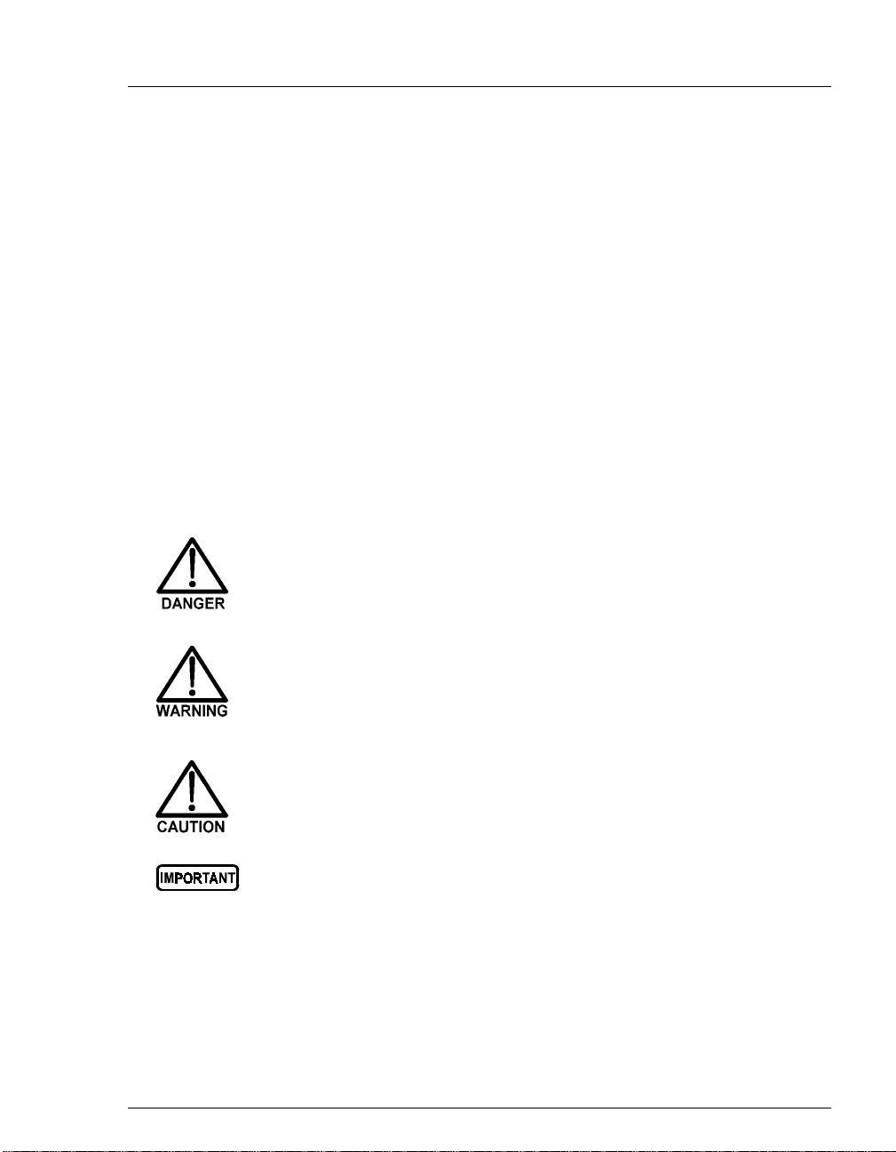
1.2.2 Safety Messages and Notes
This manual contains warnings and precautionary statements that can
prevent personal injury and/or damage to the CD25 when properly
followed. Safety messages appear in bold type and are accompanied by
icons, as shown below.
Indicates an imminently hazardous situation which, if not
avoided, will result in death or serious injury.
Indicates a potentially hazardous situation which, if not
avoided, could result in death or serious injury.
Indicates a potentially hazardous situation which, if not
avoided, may result in minor or moderate injury.
Indicates that the function or process of the instrument may be
impaired. Operation does not constitute a hazard.
Doc. 031687-01 04/2000
1-3
Page 12

CD25 Conductivity Detector
Informational messages also appear throughout this manual. These are labeled
NOTE and are in bold type:
NOTE NOTES call attention to certain information. They alert
you to an unexpected result of an action, suggest how to
optimize instrument performance, etc.
1.3 Safety Labels
The CE and GS safety label on the CD25 attests to compliance with the following
European, EMC, and safety requirements: Council Directives 73/23/EEC and 89/
336/EEC, EN 61010-1:1993 (safety), EN 50082-1:1992 (susceptibility), and EN
55011:1991 (emissions).
The symbols below appear on the CD25 or on CD25 labels.
Alternating current
˜
Protective conductor terminal (earth ground)
Power supply is on
Power supply is off
1-4
Doc. 031687-01 04/2000
Page 13

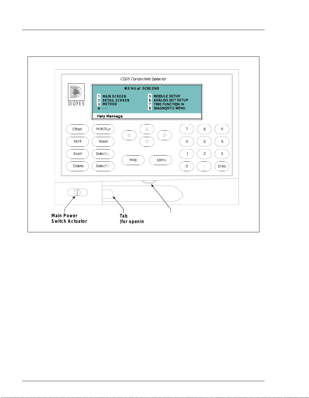
2.1 Front Control Panel
The control panel on the f ront door of t he CD25 contains the liquid crystal di splay
(LCD), the membrane keypad, and the actuator for the main power switch. The
electronics chassis, described in Section 2.1.3, is located behind the front door.
Power Switches
The main power switch is on a bulkhead inside the electronics chassis (in the
front, left-hand corner). The actuator for the power switch is on the front door,
below the control panel (see Figure 2.1.2). The actuator functions only when the
front door is fully closed. When the door is open, press the main power switch to
turn the CD25 on and off.
2.1.1 Control Panel Display
2 • Description
and
screen
, displays CD25 status and operating
Menu
buttons (see Figure 2-1).
option on the
MODULE SETUP
screen
The LCD, also called the
information. Fields on the sc ree n tha t ar e in reverse video (blue lette rs on
a white background) can be edited, while normal video fields are simply
informational displays.
To adjust the screen contrast, rotate the knurled knob in the recess
below the
To adjust the brightness of the screen backlight, select a different
DISPLAY PANEL BACKLIGHT
(see Section C.1.5).
Help
Doc. 031687-01 04/2000
2-1
Page 14
CD25 Conductivity Detector
MAIN SCREEN
DETAIL SCREEN
METHOD
---
E
!
"
Main Power
Switch Actuator
Ta b
(for opening
the door)
Figure 2-1. CD25 Front Panel
2.1.2 Control Panel Keypad
The buttons on the front panel keypad are used to affect screen functions,
to directly control CD25 operat ion, and to create and modif y programmed
series of timed events, called methods. For example, pressing
turns the method clock off
displays a list of availa ble screens. In summary:
To go from a menu to a screen, press the number button that
corresponds to the screen’s number on the menu, or move the cursor
to the desired screen name and press
Hold
(
Knob
(for a d ju s tin g
the contrast)
) and on
Run
, while pressing
(
)
Enter
.
#
Hold/Run
Menu
2-2
To edit a reverse video entry field on a screen, move the cursor to the
field using the four directional arrow buttons. Then, use the numeric
Doc. 031687-01 04/2000
Page 15

2•Description
Keypad
Buttons
Offset
Mark
buttons to enter variable values or the
Select
∆
and
Select
∇
to choose predetermined values.
In most cases, confirm the selected value, by pressing either a cursor
arrow button or
must press
METHOD SAVE TO
the
command, the
NOTE A beep sounds each time you press a keypad button,
and a lower frequency beep sounds whenever an
error occurs. You can disable the beeps from the
MODULE SETUP
Function
Returns the analog (recorder) output to a predetermined baseline and
zeros the display. The resultant value of the offset required is displayed
on the
Sends a 10% positive event mark to the analog (recorder) output. A
mark is typically used to indicate a sample injection. This fun ction can
be programmed in a method.
Enter
. In certain fields and/or screens, however, you
Enter
to confirm the selected value. These exception s are
field, the
DIAGNOSTIC TESTS
DETAIL
screen. This function can be programmed in a method.
METHOD RUN
field, any calibration
screen, and all menu screens.
screen (see Section C.1.5).
buttons
Insert
Doc. 031687-01 04/2000
Inserts a new step into a method.
T o add a new s tep, mov e the cur sor to the
A new blank step appears below the cursor position. After entering a
time value, press
order and they will be automatically reorganized in the correct
chronological order.
Enter
or a cursor arrow button. Insert steps in any
TIME
field and pr
ess
Insert
.
2-3
Page 16

CD25 Conductivity Detector
Keypad
Buttons
Delete
Hold/Run
Function
Removes the value from the curren t entry field. To restore the previous
value, move the cursor from the field before entering a new value.
Pressing
METHOD
Delete
when the cursor is in a step entry field on the
screen “blanks” the step parameter value. Moving the cu rsor
to another field does not restore the previous value; instead, the step
remains blank, indicating no change from the previous step .
To delete an entire method step:
1. Position the cursor in the method’s time field and press
Delete
.
The time is removed and the help line prompts you to press
Delete
again to delete the step.
2. Press
Turns the method clock off (
Delete
again. Or, to restore the original time and step
parameters, press any button except
Hold
) and on
Delete
(Run)
.
. This button
functions only when the detector is under Method control (see
Section 2.5.3).
When the method clock is in Hold, pressi ng
Hold/Run
starts the clock
at either the initial step of a new method or, if resuming an interrupted
method, at the time at which the clock was put in Hold.
2-4
Rese
Select
and
Select
When the method clock is in Run, pressing
Hold/Run
stops the
method clock, thereby “holding” the method and freezing the current
conditions.
t
Changes the method clock time to
INIT
, causing the initial conditions
specified by the method to occur. This button functions only when the
detector is under Method control (see Section 2.5.3).
If the method is running, it continues running. If the method is in Hold,
the method clock executes the initial conditions and holds.
∆
When the cursor is positioned at a field with predetermined
parameters, these buttons cycle through the options. In fields with
∇
predetermined numerical values, pressing
Select
Enter
Select
button increases (or decreases) the value
by one unit; pressing
Holding down a
continuously. Press
∇ decreases the value by one unit.
or a cursor arrow button to confirm the
Select
increases the value
∆
selected value.
Doc. 031687-01 04/2000
Page 17

2•Description
Keypad
Buttons
Help
Menu
Numeric
Buttons
Function
The four cursor buttons move the cursor, in the direction of the arrow,
to the next entry field. If there is no changeable field in that direction,
the cursor moves diagonally or remains in its current location.
In most cases, after entering a new value in an entry field, pressing an
arrow button saves and/or executes the change. The exceptions are the
METHOD SAVE T O
command, the
DIAGNOSTIC TESTS
field, the
METHOD RUN
screen, and all menu screens.
field,
any calibration
Displays a help screen with information pertaining to the current entry
field.
Displays one of two menus, depending on the current screen:
From an operational screen, pressing
SCREENS
From a diagnostic screen, pressing
DIAGNOSTIC MENU
MENU of SCREENS
.
; pressing
.
Menu
displays the
Menu
once returns you to the
Menu
again returns you to the
MENU of
Enters numeric values into the current e ntry field. The numer ic buttons
are 0 through 9 and the decimal.
From a menu screen, pressing a numeric button opens the
corresponding screen.
Enter
Doc. 031687-01 04/2000
Saves and/or executes changes made in entry fields. I f a menu screen is
displayed, pressing
Enter
opens the highlighed screen.
2-5
Page 18

CD25 Conductivity Detector
2.1.3 Initial Display Screens
When the CD25 has successfully powered-up and passed all diagnostic
tests, the
the
power-up, the
screen. See Section C.2.7 if this occurs.
POWER-UP
MAIN
screen (see Figure 2-3). If one of the diagnostic tests fails at
DIAGNOSTIC TEST
screen (see Figure 2-2) displays briefly, followed by
screen disp lays instead of the
MAIN
NOTE The information on the
reviewed at any time by selecting the screen from
DIAGNOSTIC MENU
the
CD25 CONDUCTIVITY DETECTOR
MODULEWARE REV
Help M essag e
Figure 2-2. Power-Up Screen
+2. 34
uS
POWER-UP
.
TOTA L 138.71 uS
RANGE
screen can be
BIO S REV n.nn
SRS
n.nn
nnnnnnDX L-AN ID#
50
1000 uS
2-6
LOCAL
H e lp Mess a g e
MAIN
The
facilitate viewing from a d istance. Operating parameters (flow rate,
method number to run, etc.) are selected here.
screen dis plays status information in enlarged characters to
METHOD 05
Figure 2-3. Main Screen
Doc. 031687-01 04/2000
Page 19

2•Description
To access other screens, press the
display the
MENU of SCREENS
Menu
(see Figure 2-4). T o select an opti on, move
the cursor to a screen name and press
on the keypad and press
Enter
. See Appendix C for a description of each
screen.
MENU of SCREENS
MAIN SCREEN
1
DETAIL SCREEN
2
METHOD
3
- - -
4
5
6
7
8
Help Message
Figure 2-4. Menu of Screens
button on the front panel to
Enter
, or enter the screen number
MODULE SETUP
ANALOG OUT SETUP
TIME FUNCTION IN
DIAGNO STIC MENU
Doc. 031687-01 04/2000
2-7
Page 20
CD25 Conductivity Detector
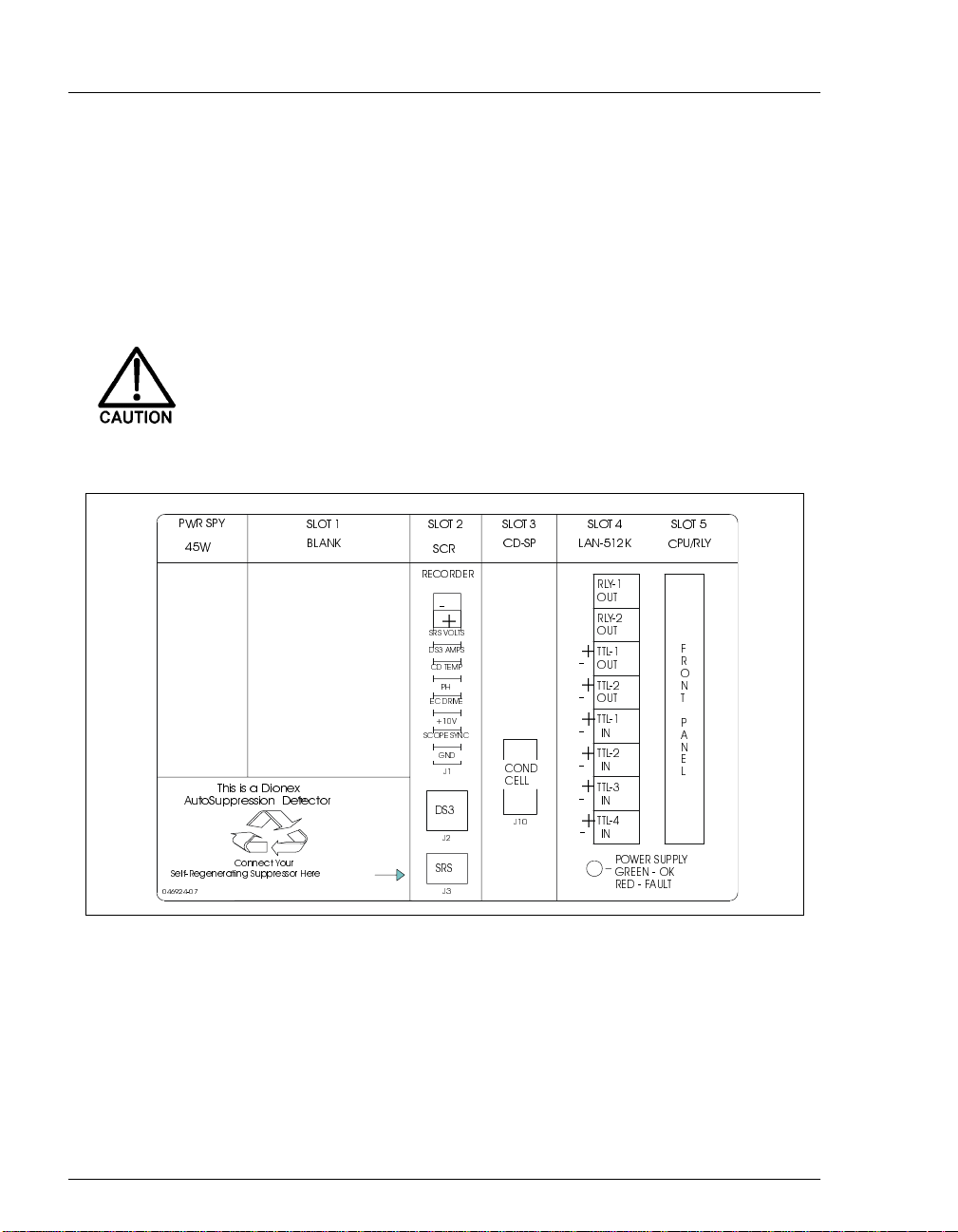
2.2 Electronics Chassis
The electronics chassis is located immediately behind the front door of the CD25 .
The chassis contai ns several el ectronics ca rds (printe d circuit boa rds) that ar e used
to control the CD25. Various connectors on the cards allow communication
between the CD25 and other system modules and accessories. Figure 2-5
identifies the cards and their connectors.
Do not remove any of the electronics card s from the detector.
There are no user-serviceable components on the cards. If
servicing is required, it must be performed by qualified
personnel using appropriate electrostatic discharge (ESD)
handling procedures.
Figure 2-5. CD25 Electronics Chassis Components
#"
!
$
!"
2-8
Doc. 031687-01 04/2000
Page 21

2.2.1 Connectors
Recorder (Slot 2)
This connector is typi cally used for a recorder/integrator or diagnostic
instruments. For a description of the connector pinouts, see Table F-1 in
Appendix F. For connection instructions, see Section B.2.7.
DS3 (Slot 2)
The control cable from the DS3 Detection Stabilizer connects here.
SRS® (Slot 2)
The control cable from the Self-Regener at ing Suppressor® conne ct s her e.
Conductivity Cell (Slot 3)
The conductivity cell cable connects here.
TTL/Relay (Slot 4)
This strip of eight connectors provides an interface with Dionex and nonDionex modules for TTL and relay control of the detector. See
Appendix D for a description of relay and TTL functions and the
connections between the CD25 and other modules.
2 • Description
60-pin Ribbon Connector (Slot 5)
The 60-pin ribbon cable to the CD25 front panel (display and keypad)
connects here.
2.2.2 Cards
Power Supply Card
Provides 45 watts of power for the detector electronics.
Blank Card
Slot 1 contains a blank card that must be present to complete the
electromag netic interference (EMI) shielding.
Doc. 031687-01 04/2000
2-9
Page 22

CD25 Conductivity Detector
SCR (Supply Control/Relay) Card
Interfaces to the CPU; th e card contains three functions:
16-bit Recorder Output Digital-to-Analog Converter
electronic switch for selection of full-scale outputs of 0.01, 0.1, and
1.0 V.
SRS Power Supply
50, 100, 300, or 500 mA to the suppressor. An over-voltage detector
shuts off the power i f the vol tage ex cee ds 8.5 V. An over- temp eratur e
detector shuts off the power if the SRS temperature excee ds 40
either of these events o ccurs, the S CR card sends an “SRS Alarm”
error message to the CPU.
DS3 Power Supply
Stabilizer . While warmi ng or coolin g to a lowe r set poin t, a “BELOW
TEMP” or “ABOVE TEMP” message is displayed. Once a set point
in the range of 25 to 45
maintains a constant temperature .
SP (Signal Processor) Card
—Includes an
—Supplies a regulated current (set by the user) of
°
C. If
—Supplies heating power to the DS3 Detection
°
C is reached, proportional heat control
2-10
Contains all the analog circuitry needed by the CD25, as well as the
digital circuitry required to interface to the CPU. See Appendix E for a
list of SP ca rd functions.
Relay/DX-LAN and CPU Cards
The CD25 control Moduleware and BIOS reside on the CPU card.
The CPU card provides control and monitoring of other modules. A
60-pin ribbon cable assembly links the logic to the CD25 front panel
display a nd keypad .
The Relay I/O card provides two isolated low voltage relay outputs,
two TTL outputs, and four TTL inputs.
The cards are installed in slot 5 of the card cage. The Relay card is a halfcard which rides piggyback on the CPU card and sits behind slot 4.
The Relay I/O card is short enough to allow th e optional detector interface
card (P/N 044196) to be mount ed behi nd it in slot 4. The interface card is
required for communica tion bet ween the CD25 an d PeakNet so ft ware via
the DX-LAN.
Doc. 031687-01 04/2000
Page 23

2 • Description
Power Supply LED
The multicolored LED below the TTL/Relay connections indicates the
power supply status:
A green LED indicates normal operation.
A red LED indicates a fault conditi on. When a fault occurs, th e CD25
enters its diagnostic state and no other control is permitted until the
problem is corrected. Turning off the power for a few seconds may
clear the fault; however, if the red LED is lighted when you turn on
the power again, notify Dionex.
Doc. 031687-01 04/2000
2-11
Page 24

CD25 Conductivity Detector
2.3 Conductivity Cell
The flow-through conductivity cell has an active volume of about 1.0 µL. T wo
316 stainless stee l elect rodes are permanentl y sealed into the PEEK cell bo dy. The
cell constant has a nominal value of 160 cm
sensor located slightly downstream from the electrodes senses the temperature of
liquid passing thro ugh the cell. The me asured value is used to provid e temperature
compensation.
The advanced geometry of the cell provides several benefits:
Excellent accuracy and linearity over the working range
Efficient sweepout and low volume for low dispersion
Reduced sensitivity to electrode surface conditions
Low electrode mass
Effective temperature compensation
You can order the conductivity cell installed in a DS3 Detection Stabilizer
(P/N 044130) for temperature control, or installed in an electrical shield
(P/N 044132) which provides no temperature control. Bec ause th e DS3 maintai ns
a constant temperature, thus reducing the effects of variations in laboratory
temperature, the DS3 is recommended for conductivity detection.
-1
and is calibrated electronically. A
2-12
Temperature Control and Compensation
Temperature directly affects the conductivity of a solution. As conductivity
increases, the effect of temperature changes becomes more pronounced. For
example, building temperature control systems can cause a regular oscillation in
the baseline. This, in turn, can affect the reproducibility of an analysis.
In ion chromatography, suppressing eluent conductivity minimizes the effect of
temperature variation. Temperature compensation further improves baseline
stability. When the conductivity cell is housed in a DS3 Detection Stabilizer, the
DS3 enhances the ability of these techniques to reduce temperature effects below
the detection limit.
Temperature compensation also ensures that th ere will be no major chang e in the
baseline or peak heights, should it be necessary to change the DS3 operating set
°
point. Readings will be normalized to 25
C.
Doc. 031687-01 04/2000
Page 25

2.3.1 DS3 Detection Stabilizer
The DS3 is a temperature-controll ed chamber c onsisting of a cast
aluminum base and cover enclosed in insulating foam. The chamber
houses both the conductivity cell and the eluent heat exchanger.
Figure 2-6 identifies the major components of the DS3.
The DS3 provides the following benefits:
Conductivity measurements that are nearly impervious to laboratory
temperature variation
Very low dispersion in the eluent heat exchanger
Excellent peak height reproducibility
Remote mo unting after either the column or suppressor
User-settable temperature
Power input to a pair of trans istors on op posite sid es of the DS3 heat s it to
°
a set temperature from 25
outlet senses the eluent temperature. The CD25 circuitry compares this
temperature with the user-selected temperature and adjusts the heat input
in real time to hold the temperature within a few millidegrees.
C to 45 °C. A sensor near the heat exchanger
2 • Description
The DS3 is sealed with an O-ring to trap eluent that may leak from the
cell. If 5 mL of liquid acc umulates, a thermistor s ensor becomes
immersed and signals a leak to the CPU. Any additional leakage will be
discharged via the spill/overflow line. A second thermistor, above the
discharge level, acts as a temperature re ference for the leak sensor.
Doc. 031687-01 04/2000
2-13
Page 26
CD25 Conductivity Detector
To Detector
Electronic s
Conductivity Cell
Ground Wire
Ce ll Inlet
Figure 2-6. DS3 Detection Stabilizer
2.3.2 Shielded Cell
A conductivity cell installed in an electrical shield (P/N 044132) is
available. The shield is a stainless steel housing that protects the cell from
electromagnetic interference (EMI), but does not provide temperature
control.
DS3
Inle t
DS3
Outlet
Sp ill/Overflo w
Line
DS3
Enclosure
Keyhole Mounting
Slots
2-14
Doc. 031687-01 04/2000
Page 27

2.4 Rear Panel
The CD25 rear panel (see Figure B-1) contains fuses, connectors for line power,
and a connection for the optional DX-LAN interface.
DX-LAN Connection (Optional)
When you order the DX-LAN network, a DX-LAN connector is factory-installed
in the upper left corner of the CD25 r ear panel (see Figure B-1). See Appendix B
for DX-LAN interface connection instructions.
External Connection Access
Connections to the front of the electronics chassis, such as TTL and relay cables,
are usually rout ed to t he back of the d etector through t he cab le chase in the bo ttom
of the electroni cs chass is. The y may also be pass ed throug h slots at the front o f the
detector. Cables exit the CD25 through an opening in the rear panel (see
Figure B-1).
2 • Description
Doc. 031687-01 04/2000
2-15
Page 28

CD25 Conductivity Detector
2.5 Functional Description
2.5.1 Operating and Control Modes
The operating mode determines
how
the CD25 receives operating
commands:
In Local mode, the CD25 receives commands from the front control
panel buttons and screens.
In Locked Remote mode, PeakNet 6 software sends commands from
the host computer via the DX-LAN interface.
The control mode determines
In Direct control, the CD25 executes commands immediately.
In Method control, the CD25 executes commands according to the
when
operating commands are executed.
timed steps in a method. The method is programmed from the CD25
front panel.
The table below summarizes the various operating and control mode
MAIN
configurations. Select the modes from the
Section C.1.2),
DETAIL
screen (see Section C.1.3), or chromatography
screen (see
software.
Operating/Control Mode Detector Operation
Local/Direct Control Commands are entered from the CD25 front control
panel and executed immediately after being entered.
2-16
Local/Method Commands are entered from the CD25 front control
panel and executed by running a method programmed
from the front panel.
Locked Remote/Direct
Control
Commands are sent from PeakNet 6 and executed
immediately when received.
Doc. 031687-01 04/2000
Page 29

2.5.2 Local and Remote Modes
Local Mode
When the CD25 is powered up, it is a lways in Loc al mode. In Loc al mode
the detector accepts operating commands from two sources:
Direct input from the front panel keypad and screens. All operating
functions are available with direct input.
TTL inputs from a remote controller (for example, a Dionex gradient
pump module or an integrator). TTL signals can be used to offset the
recorder, run a method, turn the SRS off and on, send a mark to the
recorder, and increase the recorder range.
Locked Remote Mode
In Locked Remote mode, the CD25 accepts operating commands from a
Dionex data station via the DX-LAN.
In Locked Remote mode, all operating changes from the front panel are
disabled. Selecting the Connect command from PeakNet 6 immediately
selects the Locked Remote mode. To return the CD25 to Local mode,
select the Disconnect command, or turn off the CD25 power.
2 • Description
2.5.3 Method Control
In Method control, commands are executed according to the time-based
steps specified in a metho d. Methods are crea ted, edite d, and saved on the
METHOD
instructions.
METHOD EDIT SAVE TO
TEMP COMP
TIME
INIT
0.00
2.00
Help M essag e
Doc. 031687-01 04/2000
screen (see Figure 2-7). See Section 3.3 for programming
RUN
RANGE
200 uS
v
1.6
OFFSET MARK
**
Figure 2-7. Method Screen
3333
SRS 100DS3 TEMP 40
TTL RLY
1
0
1
25
212
000
1
2-17
Page 30

CD25 Conductivity Detector
The following summarizes basic information about using methods:
The CD25 can run under method control while you are entering or
editing any method (including the one that is currently running).
When saving changes to the currently running method, or switching
to a different method, the method cloc k continue s running unaf fected.
Only those p arameter changes which affect the method after the
current time will be implemented in the current run.
The CD25 can store up to 100 separate methods (0 through 99) in
memory. The actual number, which depends on the size of each
method and the amount of available memory, is typically less than
this.
Methods are retained in memory even after the CD25 is powered
down.
Each method can have a maximum of 32 time-based steps. Step 1
always starts at
0.0.
INIT
(initial conditions). Step 2 always starts at
TIME
=
2-18
Doc. 031687-01 04/2000
Page 31

3 • Operation and Maintenance
3.1 Getting Ready to Run
NOTE The CD25 is designed for use with IC (ion
chromatography) and HPLC (high-performance liquid
chromatography) applications and should not be used
for any other purpose. If there is a question regarding
appropriate usage, contact Dionex before proceeding.
After installing the CD25 Conductivity Detector, or after the power has been off
for some time, use the following check list to ready the detector for operation.
Verify that all cables are correctly connected to the CD25.
Verify that the CD25 power cord is plugged into the main power.
Press the power switch actuator on the CD25 front panel (see Figure 2-1) to
turn on the power. The
diagnostic tests begin running. If the tests are successfully completed, the
MAIN
screen appears after a few seconds. If one or more tests fails, the
DIAGNOSTIC TEST
POWER-UP
screen appears, inst ead.
screen displays briefly and then some
If the conductivity cell is in a DS3 Detec t ion Stabiliz er, set the DS3
temperature from the
guidelines:
If the DS3 is installed in a non-temperature controlled module, for
example, an LC10 Chromatography Organizer or LC20 Chromatography
Enclosure, select a temperature at least 5 °C above the highest expected
ambient temperature surrounding the DS3.
If the DS3 is installed in an LC30 Chromatography Oven, select a
temperature at least 5 °C above th e oven te mperatu re. Do not set t he oven
temperature above 40 °C (104 °F).
Turn on the DS3 power. The DS3 will begin warming up at about
1 °C/minute. Baseline conducti vit y should stabilize once the DS3 reaches the
selected temperature.
Doc. 031687-01 04/2000
DETAIL
screen (see Section C.1.3), according to these
3-1
Page 32

CD25 Conductivity Detector
As soon as the proper current is determined and eluent is flowing through the
Self-Regenerating Suppressor (SRS) at the correct rate, turn on the SRS. (The
SRS power is always off when the CD25 is powered up.) After start-up, the
usual direction of drift is downward as SRS efficiency improves.
While waiting for acceptable drift, you may want to select a lower sensitivity.
Set the offset to 50%.
When you are ready to start a run, select the desired sensitivity and offset (if
you have not already do ne so). Pr ess
Offset
before injection and du ri ng a run,
also, if nec essary.
3.2 Running Under Direct Control (Local Mode)
In the Direct cont rol operat ing mod e, commands a re ca rrie d out immediat ely a fter
they are entered. All detector pa ramete rs remai n in ef fect unti l new comma nds are
entered. Because ther e ar e no ti me- base d st eps, the method clock is not used. The
Hold/Run
and
Reset
buttons are not operable in Direct control.
Select Direct control from the
DIRECT CNTRL
If
is displayed, this mode is already selected and no action is
necessary.
METHOD
If
Select
or
is displayed, move the cursor to
∇
button to toggle to
button to activate the selection.
MAIN
or
DIRECT CNTRL
DETAIL
screen, as follows:
METHOD
. Press
and press the
Enter
or a cursor arrow
Select
∆
3-2
Doc. 031687-01 04/2000
Page 33

3 • Operation and Maintenance
3.3 Running Under Method Contr ol (Local Mode)
In the Method control operating mode, the CD25 is controlled by a series of
programmed timed events, known as a
even after the detector power is turned off.
3.3.1 Running a Method
method
. Methods are retained in memory
1. Go to the
CNTRL
to
2. In the
METHOD
Enter
or a cursor arrow button.
NOTE The method can also be selected from the
MAIN
METHOD
DETAIL
or
screen. If necessary, toggle from
.
field, enter the desired method number and press
METHOD
the
screen. Enter the method number in
RUN
field and press Enter.
DIRECT
3. If the method clock is already running, the method will start as soon
as you enter the method number. If the clock is in Hold, press
Hold/Run
to start the method.
4. The elapsed time on the method clock when the method begins
determines at which step the method begi ns runni ng:
If the method clock is at
running using the
INIT
INIT
or time zero, the method begins
condition parameters, f ollowed by the t ime
zero step. The remaining steps are executed according to their
programmed times.
If the method clock is greater than zero, the method begins
running using the paramete rs speci fi ed in the step for the elapsed
time. To start the method at the
Reset
.
INIT
conditions instead, press
3.3.2 Changing the Running Method
To switch from the method currently running to a different method, enter
the new method number in the
Enter
. The new method will begin running, using the parameters
specified in the step for the current elapsed time. If you prefer to start the
method at the
Doc. 031687-01 04/2000
INIT
conditions, press
RUN
field on the
Reset.
METHOD
screen and press
3-3
Page 34

CD25 Conductivity Detector
3.3.3 Creating a New Method
1. Go to the
METHOD
screen. In the
number from 0 through 99 and press
EDIT
field, enter an
Enter
unused
method
or a cursor arrow button.
This displays a blank method on the screen.
The first step of every meth od is an in itia l condi tions step wi th
TIME
the
TIME
field. The second step is always a time step with 0.00 in the
field. You cannot delete these steps, although you can change
their parameters.
2. Enter the parameters for the initial conditions and time 0.00 steps.
NOTE The
METHOD EDIT SAVE TO
TEMP COMP
TIME
field is the only field in each method step
that must have an entered value. Leaving any other
field blank indicates that the value selected for that
parameter in the preceding step is still in effect.
RUN
3333
1.6
25
SRS 100DS 3 TE M P 40
TTL RLY
TIME
INIT
0.00
2.00
RANGE
200 uS
v
OFFSE T M ARK
**
1
212
0
000
1
1
Help M essage
INIT
in
3-4
Figure 3-1. Method Screen
3. To create a new method step, move the cursor to a blank
TIME
field,
enter the time (in minutes) for the action to be performed, and press
Enter
or a cursor arrow button. Enter a value for each step parameter,
or leave a field blank if you want the value selected in the preceding
step to remain in effect.
4. Repeat Step 3 for each additional step. Up to 30 steps can be added
after the time 0.00 step.
Sometimes a method contains more steps than can be seen on the
v
screen at one time. If there is a small
bottom of the screen, move the cursor
next to the time entry at the
down
to view additional steps.
If there is a caret (^) next to the top tim e entry, move the cursor up to
view additional steps.
Doc. 031687-01 04/2000
Page 35

3 • Operation and Maintenance
5. To save the new method, move the cursor to the
the number that appears in the
3.3.4 Editi n g an Ex is ting Method
NOTE Once you sav e chan ges to a m eth od, t here i s no way
to recall the original method. To make experimental
changes while retainin g th e orig inal me thod , be s u r e
to save the new method, or a copy of the original
method, under a different method number.
Y ou can modify an existi ng method by changing, ad ding, or deletin g steps
and/or parameters. If the method you are editing is currently running, the
changes are stored in memory and implemented when you save the
method.
To edit an existing method, go to the
number in the
Follow the editing instructions in the appropriate section below. When
you finish, save t he cha nges t o the curr ent me thod nu mber or s elect a ne w
number.
Changing Method Parameters
EDIT
field, and press
EDIT
field, and press
METHOD
Enter
screen, enter the method
or a cursor arrow button.
SAVE TO
Enter
field, enter
.
Move the cursor to the desired field and enter a new value, using the
CD25 front panel buttons. Press
editing change.
Adding a Method Step
There are two ways to add a step to an existing method:
Doc. 031687-01 04/2000
Enter
or a cursor arrow button after each
Move the cursor on the
METHOD
screen to any
time and pa rameters for the new step, and press
TIME
field. Enter the
Enter
or a cursor
arrow button. If neces sary , the step will automatical ly be moved to th e
correct chronological point in the method.
Move the cursor on the
preceding the intended location of the new step. Press
METHOD
screen to the line immediately
Insert
to insert
a blank line below the cursor location . Enter the time and parameters
for the new step, and the n press
Enter
or a cursor arrow button.
3-5
Page 36

CD25 Conductivity Detector
Deleting a Method Step
Delete
METHOD
twice.
METHOD
screen to t he time of the step to be
screen to the
EDIT
Move the cursor on the
deleted and press
Deleting an Entire Method
Move the cursor o n the
twice.
Saving a Modified Method
replace
To
of the original method in the
retain
To
the original me th od wi t h a m odi fi ed version, ente r the number
SAVE TO
field and press
the original method an d sa ve t he modi fi ed version elsewhere in
memory, enter an unused method number in the
Enter
.
field and press
Enter
.
SAVE TO
field and press
Delete
3-6
Doc. 031687-01 04/2000
Page 37

3 • Operation and Maintenance
3.4 Optimizing Temperature Compensation
The CD25 built-in temperature compensation stabilizes conductivity readings by
correcting for changes in ambient temperature that occur during a run. For more
information about temperature control and compensation, see Section 2.3.
3.4.1 With a DS3 and Conductivity Cell
If the ambient temperature exceeds 45 °C, the DS3 may be
permanently damaged. If the DS3 is installed in an LC30
Chromatography Oven, do not se t the ov en temp erat ure abo v e
40 °C (104 °F).
Housing the cell in a DS3 Detection S tabilizer ensures that there is no
more than a minor temperature varia tion in liquid re aching th e cell. Thus ,
TEMP COMP
the
setting on the
Many users are able to keep their systems at a single operating
temperature. For optimal accuracy, calibrate the cell at this temperature,
using the proper temperature coefficient setting. If you later reset the
temperature, the CD25 temperature compensation will normalize
conductivity measurements to 25 °C (77 °F) to prevent a major upset in
system calibration. If you change the DS3 set point, recalibrate the cell.
DETAIL
screen can remain at 1.7% per ºC.
If temperature-induced baseline cycling occurs, it is probably caused by
another component of the chromatography system. If the variation
increases as the eluent reservoir empties, move the reservoir to a more
temperature-stable environment and/or wrap the reservoir in thermal
insulation.
Doc. 031687-01 04/2000
3-7
Page 38

CD25 Conductivity Detector
3.4.2 With a Shielded Conductivity Cell
When the conductivity cell is not inside a DS3 Detection Stabilizer, actual
conductivity drifts up and down with fluctuations in laboratory
temperature. This is especially noticeable when the thermostat cycles on
and off in laboratories with very high air turnover rates and controlled
temperature. Selecting the proper temperature compensation factor will
minimize the effect of temperature fluctuations.
Start by setting
TEMP COMP
baseline variation of the same period as the laboratory cooling or heating
occurs, increase or decrease the temperature compensation setting.
Continue adjusting it until you find the optimal setting. This is typically
between 1.5% to 2% per ºC, suppressed or non-suppressed.
If you notice a slowly increasing or decreasing baseline drift in a
laboratory with out a te mperature control system, l ook for a cor responding
temperature drift. If there is a correlation, adjust the temperature
compensation setting until you find the optimal setting.
3.5 Routine Maintenance
This section describes routine maintenance procedures that can be performed by
the user. Any other maintenance procedures must be performed by qualified
Dionex personnel.
NOTE The CD25 electronic components are not customer-
serviceable. Repair of electronic components must be
performed by Dionex.
Periodically check liquid line conne ctions to the cell (inside the
chromatography module) for leaks, and clean up any spills.
on the
DETAIL
screen to 1.7%. If a sinusoidal
3-8
Doc. 031687-01 04/2000
Page 39

This chapter is a guide to troubleshooting problems that may occur while
operating the CD25 Conduc ti vi ty De te ctor. Turn to the section that b est des cr ibe s
the operating problem. There, the possible causes of the problem are listed in
order of probability, along with the recommended courses of action. For
additional help, refer to Appendix C for instructions on running the CD25
diagnostics program.
If you are unable to eliminate a problem, contact Dionex. In the U.S., call 1-800346-6390 and select the Technical Support option. Outside the U.S., call the
nearest Dionex office.
4.1 No Detector Response
Cell is off
4 • Troubleshooting
Turn on the cell (from the
Analog output range set too high; although the display indicates a
response, no recorder response observed
Select a more sensitive analog output range.
Wrong full-scale output (or no full-scal e output) selected
Select 0.01, 0.10, or 1 volt full-scale.
No flow from pump
Check the pressure reading on the pump to verify that the pump is on.
Detector o f fset out of range
Offset
Press
on the CD25 front panel.
MAIN
or
DETAIL
screen).
Doc. 031687-01 04/2000
4-1
Page 40

CD25 Conductivity Detector
4.2 Low Detector Output
Analog output range set too high; although the display indicates a
response, no recorder response observed
Select a more sensitive analog output range.
Insufficient sample injected
Increase the injection size or concentration.
Cell out of ca libration
Recalibrate the cell (see Section 5.4).
4.3 High Detector Output
Auto offset not activated recently
Offset
Press
Background not suppressed by SRS
Check the SRS regenerant out line for bubbles; if there are no bubbles, the
suppressor may be contaminated. Refer to the SRS manual for
troubleshooting guidanc e.
on the CD25 front panel before making an injection.
4.4 Noisy or Drifting Baseline
Flow system leak ahead of cell; erratic baseline
Check all fittings and liquid lines for leaks. Tighten or, if necessary, replace
all liquid line connections. If the connections are made with ferrule fittings,
Installation of Dionex Ferrule Fittings
4-2
first refer to
requirements.
Pump not properly primed
Prime the pump as instructed in the pump manual.
Rapid changes in ambient temperature
Redirect heating and air conditioning vents away from the cell.
Purchase a cell in a DS3 Detection Stabilizer (P/N 044130).
When using a shielded cell, install the cell in a chromatography oven.
for tightening
Doc. 031687-01 04/2000
Page 41

4 • Troubleshooting
Insufficient system equilibration following any changes to operating
parameters; especially apparent when operating at high sensitivities
Allow longer system equilibration before beginning operation.
Air trapped in cell; excessive regular pulses in baseline
Remove the trapped air (see Section 5.2). To prevent air fro m becoming
trapped in the cell in the future, increase backpressure on the cell by reducing
the inner diameter of the tubing installed after the cell and before the SRS.
Inappropriate SRS operating conditions
Refer to the SRS manual for the correct operating conditions.
Temperature compensation setting not optimized
Optimize the selected setting (see Section 3.4).
DS3 above or below set point
See Section 4.6.
Doc. 031687-01 04/2000
4-3
Page 42

CD25 Conductivity Detector
4.5 Liquid Leaks from the DS3
When a leak is detected, the DS3 leak sensor signals the CPU. If more than 5 mL
of liquid accumu lat es i n t h e DS3, the excess will be dr ained via the spill overflow
line (see Figure 2-6).
Loose or defective fittings, or overpressurization caused by a restriction
Check the waste line for blockage; a trapped particle can plug the line,
causing a restri ction and/or lea k. If necessar y , c lear the waste line by rever sing
the direction of flow.
Make sure the plumbing downst r eam f rom t he DS3 is clear; a blockage in the
plumbing may overpressurize the DS3, causing it to leak.
Make sure the downstream backpressure coils are appropriate for the
operating flow rate (see Section B.2.4).
Follow the steps below to disassemble the DS3 and inspect it for the source of
the leak. Test and dry the DS3 before reassembly.
1. Turn of f the CD25 power.
2. Disconnect the DS3 cables.
3. Disconnect the DS3 inlet and outlet lines. Do not misplace the ferrule
fittings at the end of the tubing (see Figure 4-1).
4. Remove the DS3 by lifting it upward and then pulling it away from its
mounting location. Place the DS3 on the workbench.
5. Open both latches on the DS3 and carefully lift off the top half of the
cover, along with its insulating foam insert, exposing an aluminum box
(see Figure 4-1).
6. Remove the box from the bottom half of the cover.
7. Remove the four Phillips screws securing the top of the box to its bottom
plate. Carefully separ at e t he t wo par ts , expos in g the cel l ( see Figure 4-2).
Lay the top aside, being careful not to pull or stress the group of wires that
connect the two parts.
8. Check the inlet and outlet cell fittings for leaks. Tighten or replace if
necessary.
9. Dry the DS3, test for leaks, and reassemble. Make sure the foam insert is
adjusted evenly aroun d the vari ous DS3 component s, with no pin ching or
4-4
Doc. 031687-01 04/2000
Page 43

Bo tto m
Cover
4 • Troubleshooting
folding. Check that the top and bottom inserts meet on all sides before
latching the cover.
Ins u la t in g
Cables
Foam
Ins e rt
Aluminum
Box
Inle t
Outlet
Ph illips
Screws (4)
Sp ill Ov e rf lo w
Line
Figure 4-1. DS3 Exploded View
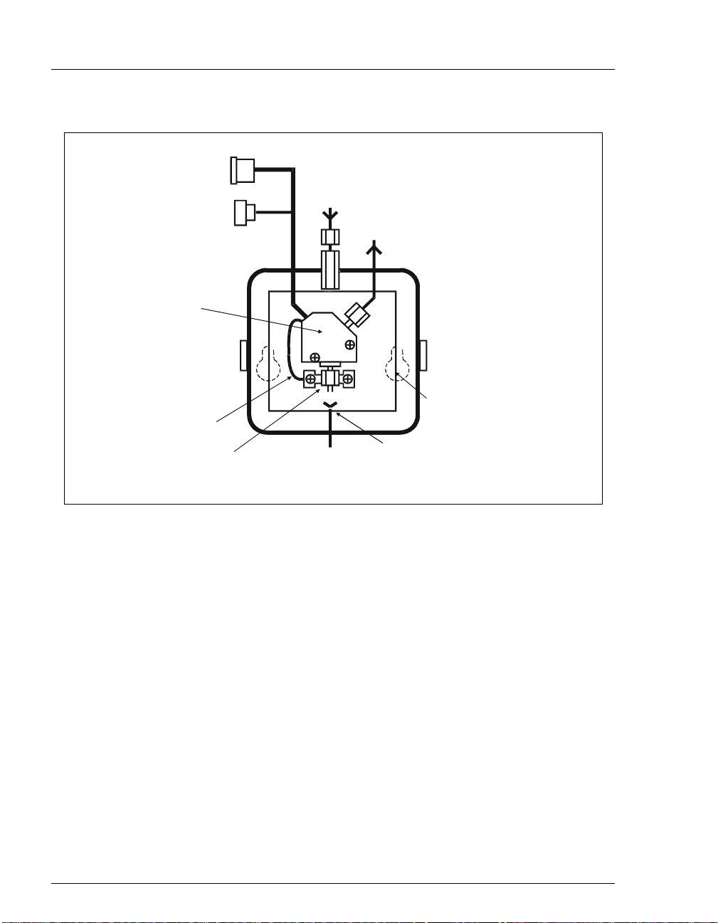
Inle t
Grounding Strap
Outlet
Cell
Outlet
Fitting
Inle t
Fitting
Figure 4-2. DS3 Interior Components
Top
Cover
Ph illi p s
Screws
Doc. 031687-01 04/2000
4-5
Page 44

CD25 Conductivity Detector
Liquid seeping from around cell cables
The cell is inoperable; return it to Dionex for repair or exchange.
4.6 DS3 Temperature Inaccurate
“DS3 SET POINT XX C READY” message displays continuously
The control sensor may be faulty. Remove the DS3 cover and measure the
temperature of the housing, using any surface thermometer. The cell sensor
can be read on the detecto r and should be wi thin 1 or 2 de gre es of the DS3 set
point tempe r ature.
“DS3 SET POINT XX C UNDER TMP” or “DS3 SET POINT XX C
OVER TMP” message displays continuously
Verify that the set temperature is at least 5 °C above the external DS3
temperature. Allow 30 to 60 minutes for the DS3 to heat or cool.
At high flow rates and temperature settings far above ambient, the DS3
requires more time to heat. In extreme cases, such as a very cold room and a
high DS3 set point, the DS3 may not be able to reach the set point
temperature.
4-6
DS3 does not heat
Remove the cover and inspect the DS3 for broken or shorted wires or for
moisture bridging the control thermistor. If a wire is broken or shorted,
replace the wire or call Dionex for assistance. If a leak has caused a short, fix
the leak and dry the control sensor.
“DS3 SET POINT XX C READY” message displays intermittently
Make sure that the heater transistors are snug and the control sensor has not
been pulled out of the heat exchanger plate.
Doc. 031687-01 04/2000
Page 45

4.7 Conductivity Inaccurate
4 • Troubleshooting
Cell constant reported on
calibration is not 130 to 190 µS
The DS3 has not reached its set point temperature. Set the intended operating
temperature and wait until 5 minutes after the “NOT READY” message is
displayed, or until the reading is stable.
Make sure the selected temperature compensation setting is 1.7%/°C. Except
at 25 °C, an incorrect temperature co mpensation set ting can caus e an incorrec t
reading.
The 1 mM KCl calibration solution is spoiled, or there was a mixing error.
Remake the solution.
The electrodes are fouled by grease, precipitate, etc. Flush with a suitable
solvent, such as acid, and then flush with 1 mM KCl until the reading is
stable.
The cause is internal leaks, broken or shorted cell or sensor wires. Check the
sensor by comparing the cell temperature readout with the actual DS3
temperature. If necessary, return the cell to Dionex for repair.
disassemble the cell; this will break the seal and v oid your warranty.
Cell temperature readout deviates by more than 2°C from DS3 set
temperature
This indicates a serious cell or DS3 sensor problem. Call Dionex for
assistance.
CONDUCTIVITY CALIBRATION
screen after cell
Do not
4.8 Faulty DX-LAN Communication
DX-LAN interface incorrectly install ed
See Section B.2.2 for 10BASE-T connection inst ructions or Section B.2.3 for
BNC connection instructions.
Doc. 031687-01 04/2000
4-7
Page 46

CD25 Conductivity Detector
4.9 Diagnostics
NOTE The CD25 electronic components are not customer-
serviceable. Before running a diagnostic test, use the
troubleshooting information in earlier sections of
Chapter 4 to isolate problems that are unrelated to the
CD25 electronics.
The CD25 Moduleware includes several diagnostic tests of the electronics. To
access these, select the
diagnostic screens are illustrated and described in Appendix C.
DIAGNOSTIC MENU
from the
DIAG NOSTIC MENU
MENU of SCREENS
. The
POWER-UP SCREEN
1
ELAPSED TIME
2
ANALOG STATUS
3
-
4
DX LAN STATUS
5
KEYBOARD TEST
Help M essag e
Figure 4-3. Diagnostic Menu Screen
6
DIAG NOSTIC TESTS
LEAK CAL & STATUS
7
8
SIGNAL STATISTICS
9
CALIBRATE CD CELL
10
4-8
Doc. 031687-01 04/2000
Page 47

5 • Service
This chapter describes routine service procedures that the user can perform. All
other procedures must be performed by Dionex personnel.
NOTE The CD25 electronics components are not customer-
serviceable. Repair of electronics components must be
performed by Dionex.
The CPU card contains a lithium battery. If the CPU card is
replaced, dispose of the used battery according to the
manufacturer's instructions.
Before replacing any parts, refer to th e troubleshooting information in Ch apter 4
to isolate the cause of the problem. To contact Dionex in the U.S., call 1-800-3466390 and select the Technical Support option. Outside the U.S., call the nearest
Dionex office.
Substituting non-Dionex parts may impair CD25 performance, thereby voiding
the product warranty. Refer to the warranty statement in the Dionex Terms and
Conditions for more information.
Doc. 031687-01 04/2000
5-1
Page 48

CD25 Conductivity Detector
5.1 Eliminating Liquid Leaks
The PEEK version of the CD25 is plumbed with 1.60-mm (1/16-in) OD PEEK
tubing, Dionex ferrule fittings (P/N 043276), and 10-32 fitting bolts (P/N
043275). For tightening requirements, refer to
Fittings
.
Installation of Dionex Ferrule
5.2 Removing Trapped Air from the Cell
Air bubbles in the cell can cause regular pulsations of the baseline, random
noise, and low r eadings. Ai r may have bee n intr oduced in the columns d uring
installation, or ma y result from outgassing of the mobi le phase. Connecting a
backpressure line to the cell applies enough backpressure to shrink bubbles,
thereby allow ing them to pass more easily through the cell.
1. Connect a piece of 0.25-mm (0.010-in) ID tubing (P/N 042690), with fittings
on both ends, to the cell outlet. Make the line 1 m long for a flow rate of
1.0 mL/min, 2 m for 0.5 mL/min, etc.
2. Use tubing with an inn er diameter of at least 1mm (0.04 in) t he rest of the way
to the waste containe r. Use a union (P/N 042627) to connect the backpres sur e
line to the w aste line.
Make sure the a dded backpres sure does not exceed 0.20 MPa
(30 psi). Avoid large increases in flow rate tha t would result in
more than 1.4 MPa (200 psi) being applied to the cell.
5.3 Replacing the DS3 Cell
Follow the steps below to disassemble the DS3 and replace the cell. After
replacing the cell you must recalibrate it (see Section 5.4).
1. Turn of f the CD25 power.
2. Disconnect the DS3 cables.
3. Disconnect the DS3 inlet and outlet lines. Do not misplace the ferrule fittings
at the end of the tubing (see Figure 5-1).
4. Remove the DS3 by lifting it upward and then pulling it away from its
mounting location. Place the DS3 on the workbench.
5-2
Doc. 031687-01 04/2000
Page 49

5 • Service
5. Open both latches on the DS3 and carefully lift off the top half of the cover,
along with its insulating foam insert, exposing an aluminum box (see
Figure 4-1).
6. Remove the box from the bottom half of the cover.
7. Remove the four Phil lips screws securing the top of the box to its bottom
plate. Carefully sep arate the two par ts, exp osing t he cel l (see Figure 5-1). Lay
the top aside, bein g careful not to pull or stres s the grou p of wires t hat connec t
the two parts .
8. Disconnect the grounding strap. Remove the two cell mounting screws.
9. Rotate the cell inlet tube fitting counterclockwise. Let the cell body back
away from the fitting until the fitting threads are fully disengaged.
the ferrule
.
10. Check that the end of the inner Tefzel tubing is flush with the end of the
plastic sleeve. If nec essary, trim the sleeve slightly to prevent dis persion. Push
the tubing into the new cell until it bottoms out in the hole; then, hold the
tubing in place while tightening the nut.
11. After testing for liquid leaks, dry the DS3 and reassemble. Make sure the
foam insert is adjusted evenly around the various components, with no
pinching or folding. Before latching the cover, make sure the top and bottom
inserts meet on all sides.
Do not lose
12. Reconnect the DS3 cables and turn on the CD25 power. Calibrate the cell
constant (s ee Section 5.4).
Doc. 031687-01 04/2000
Inle t
Grounding Strap
Figure 5-1. DS3 Interior Components
Outlet
Cell
Outlet
Fitting
Inle t
Fitting
Ph illi p s
Screws
5-3
Page 50

CD25 Conductivity Detector
5.4 Calibrating the Cell
Every conductivity cell is calibr ated be fore it is shi pped from the fa ctory. The cell
calibration constant is recorded on a tag attached to the cell cable, and is also
stored in permanent detector memory for use when calculating the measured
conductivity.
The calibration const ant normal ly rema ins uncha nged, unl ess the cell i s damaged.
To check the value entered in memory, select
DIAGNOSTIC MENU
cell calibration constant shown on the screen does not match the value recorded
on the tag, do
Enter a new value, regardless of the composition of the solution in the cell.
Calibrate the cell at 147.00 µS/cm. This automatically enters a new value for
the cell calibration constant into CD25 memory.
To calibrate the cell, follow the steps below.
1. Disconnect the pump output line from the injection valve.
2. Connect the pump output directly to the inlet of the DS3 or the shielded cell.
to display the
one
of the following:
CALIBRATE CD CELL
CALIBRATE CONDUCTIVITY CELL
from the
screen. If the
3. Pump 0.001 M KCl calibration solution through the cell. Conductivity is
slightly flow-rate sensitive , so select t he flow rate used in the majority of your
applications.
4. Set
TEMP COMP
on the
5. If using a DS3, set
DETAIL
DS3 SETPOINT
screen to 1.7%.
on the
DETAIL
screen to the intended
operating point. Wait until the “DS3 READY” message appears.
6. Wait until the conductivity reading st abili zes ( within 0 .1 µS), and then, on the
CALIBRATE CONDUCTIVITY CELL
screen, select
CAL
and press
Enter
to
calibrate the cell.
7. After calibration, t he conducti vity rea ding should b e exactly 14 7.00 µS/cm. A
new value for the cell constant will be shown on the
CONDUCTIVITY CELL
screen; thi s value will al so be entered in memory.
CALIBRATE
8. Flush the KCl solution from the system by pumping deionized water through
the DS3 or cell lines. When the conductivity reading drops to near zero, stop
the pump.
9. Disconnect the pump from the DS3 or shielded cell.
5-4
Doc. 031687-01 04/2000
Page 51

5 • Service
10. Reconnect the pump to the chromatography module.
11. Reconnect the liquid line from the suppressor outlet to the cell inlet.
12. Reset
TEMP COMP
to the optima l value for the eluent.
13. S et the pump to a flow rate that is safe for the system in use.
Doc. 031687-01 04/2000
5-5
Page 52

CD25 Conductivity Detector
5.5 Replacing the Main Power Fuses
The fuse holder is in the main power receptacle on the CD25 rear panel.
1. Turn of f the main power.
HIGH VOLTAGE—Disconnect the main power cord from its
source and also from the rear panel of the CD25.
2. A recessed lock is located on each side of the fuse holder (see Figure 5-2).
Using a small screwdriver, push each lock toward the center to rel eas e it . The
fuse holder pops out approximately slightly when the locks release. When
both locks are released, pull the fuse holder straight out of its compartment.
3. The holder contains two fuses. Replace both with new 3.15 amp fast-blow
IEC127 fuses (P/N 954745). Dionex recommends replacing both fuses even
though only one is open.
4. Reinsert the fuse holder into its compartment. The fuse holder is keyed to fit
only in its proper orientation. Apply sufficient pressure evenly against the
holder to engage the two locks. The holder is flush against the panel when
both locks are engaged.
5-6
5. Reconnect the main power cord and turn on the power.
Locking Spring
Fuse Holder
Insert screwdriver
and twist to release
(each side)
M a in Po we r
Receptacle
Figure 5-2. Main Power Fuse Holder
Fuses (2)
Key
Fuse Holder
(side vie w )
Doc. 031687-01 04/2000
Page 53

5.6 Physical
A • Specifications
Dimensions
Weight
Decibel Level
A.1 Environmental
Operating
Temperature
Operating
Humidity
A.2 Electrical
Main Power
Fuses
22.5 cm W x 17.0 cm H x 42.0 cm D
(8.8 in W x 6.6 in H x 16.4 in D)
6 cm (2.4 in) clearance required behind the detector
8.2 kg (18 lb)
50 db (“A WEIGHING” setting)
4 ºC to 40 ºC (40 ºF to 104 ºF)
5 to 95% relative humidity, non-condensing
85 to 270 Vac, 47/63 Hz; 40 W Max, 25 W typical. The CD25
power supply is auto-sensing and requires no voltage
adjustment.
Two 3.15 amp fast-blow IEC127 fuses (P/N 954745)
Analog Ou tput
Doc. 031687-01 04/2000
User-selectable full-scale output of 10, 100, or 1000 mV
A-1
Page 54

CD25 Conductivity Detector
A.3 Display and Keypad
Display
Keypad
Liquid crystal display with adjustable backlighting
26-button keypad for entering commands and numerical values
for screen parameters
A.4 Detector
Range
Temperature
Compensation
Cell Drive
Local Operation
Remote
Operation
DX-LAN
Operation
(Optional)
0.01 µS to 3000 µS, full-scale
0.0 to 3.0% per ºC
Variable 8 kHz square wave
Front panel controls and display status of all functions
Control of four functions via TTL or Relay contacts
All functions can be controlled by PeakNet software on a PC
connected to the CD25 via the DX-LAN interface
A.5 Conductivity Cell
A-2
Cell Body
Active Volume
Maximum
Pressure
Electrodes
PEEK
1.0 µL
2.0 MPa (300 psi)
316 stainless steel
Doc. 031687-01 04/2000
Page 55

A.6 SRS Power Supply
A • Specifications
Supply Current
Over-Voltage
Alarm
Over-
Temperature
Alarm
50, 100, 300, 500 mA at 1.5 to 7.5 V
8.5 V
40 ºC (104 ºF)
A.7 DS3 Detection Stabilizer (Optional)
Operating
Temperature
Warm-up Time
Temperature
Alarms
25 ºC to 40 ºC (50 ºF to 104 ºF)
10 minutes (typical)
Not Ready
temperature
message displayed when under or over the set
Doc. 031687-01 04/2000
A-3
Page 56

CD25 Conductivity Detector
A-4
Doc. 031687-01 04/2000
Page 57

B.1 Facility Requirements
Make sure the CD25 installation site meets the el ectrical and environmental
specifications listed in Appendix A.
Install the CD25 on a sturdy table or workbench, at a height that ensures
convenient viewing of the front panel display.
Allow at least 6 cm (2.4 in) clear ance behind the CD25 for power con nections
and ventilation.
B.2 Installation
During installation, or whenever it is necessary to move the
detector, lift it o nly from the bottom or side. Lift ing the CD25 by
the front panel door will damage the door hinges.
B.2.1 Power Connection
The power to the CD25 can be controlled from the main power switch on
either the CD25 or the LC30 Chromatography Oven (i f prese nt). In eith er
case, no adjustment is required to select the line voltage.
B • Installation
For power on/of f contro l from the CD25, conn ect the modu lar power cord
(IEC 320 C13), from the main power receptacle on the rear panel (see
Figure B-1) to a grounded, single-phase, power source.
The power supply cord is used as the main disconnect device.
Ensure that the socket-outlet is located/installed near the
module and is easily accessible.
For power on/off control from the LC30 Chromatography Oven, connect
the IEC jumper power cord (P/N 960748) provided in the LC30 Ship Kit
from the main power recepta cle on the CD25 rear pane l to one of the four
IEC auxiliary receptacles on the rear panel of the LC30. Le ave the CD25
power switch on continuously and use the LC30 main power switch to
Doc. 031687-01 04/2000
B-1
Page 58

CD25 Conductivity Detector
turn the CD25 on and off. Other modules in the system can be connected
to the LC30 in the same way, allowing the LC30 to function as the main
power source for the system.
SHOCK HAZARD—To avoid electrical shock, a grounded
receptacle must be used. Do not operate or connect to AC
power mains without an earthed ground connection.
Operation at AC input levels outside of the specified operating
voltage range may da mage the CD25.
DX-LAN
Connector
SAFETY WARNING
SERIAL NUMBER
DX-LAN
AND
LABEL
B-2
Chase
(TTL & Relay
Lines)
Fuse Holder
M a in P ow e r
Receptacle
Figure B-1. CD25 Rear Panel
Doc. 031687-01 04/2000
Page 59

B • Installation
B.2.2 DX-LAN Interface: 10BASE-T Connections (Optional)
NOTE There are two types of DX-LAN connectors. Before
proceeding, check the CD25 rear panel. If a DXLAN 10BASE-T RJ-45 (telephone-style) connector
is installed, follow the interface instructions in
Section B.2.2. However, if a DX-LAN 10BASE-2
BNC connector is installed, follow the interface
instructions in Section B.2.3.
In order to communicate with a host computer running Dionex
chromatography software, the CD25 must contain a detector interface
card (P/N 056798) and an unshielded twisted-pair DX-LAN cable
(P/N 960281) must be connected from the RJ-45 (10BASE-T) connector
on the rear panel to a “combo” 10BASE-T Ethernet hub (P/N 056909).
Installing or Replacing the Detector Interface Card
NOTE If the DX-LAN option was not installed at the
factory, order the detector interface card kit
(P/N 057007). The kit includes all the components
required for DX-LAN communication.
STATIC—The CD25 electronics cannot be serviced by the user.
The detector interface card must be installed by qualified
personnel. Standard anti-static procedures must be observed
when installing the interface card or handling the CPU card.
To prevent damage to the CD25, turn off the main power before
installing the detector interface card. After confirming that the
LED on the CPU card is off (not green or red), unplug the
power. Do not rely on the front panel power switch.
1. To replace an existing detector interface card, remove the DX-LAN
2. Remove any TTL/Relay plugs from the connectors at slot 4 of the
Doc. 031687-01 04/2000
cable from the 10BASE-T connector on the CD25 rear panel (see
Figure B-1).
electronics chassis (see Figure 2-5).
B-3
Page 60

CD25 Conductivity Detector
3. Disconnect the 60-pin ribbon cable from the inside of the front panel
by opening the ejector latches on the connector.
4. Using a screwdriver as a lever, open the white ejector latch at the
bottom of the CPU card. Remov e the CPU card, cable, and Rel ay card
as a single unit.
5. Remove the detector interface card (if present) from slot 4 of the
electronics chassis.
6. Insert the new detector interface card (P/N 056798) into slot 4:
a. Slide the card to the rear.
b. Verify that the 10BASE-T connector is aligned with the opening
at the rear and that the card is aligned with the card connector.
c. Press firmly on the card until it mat es f ul ly wi th the connector on
the rear panel. Pull on the card to verify that it cannot move.
7. Reinstall the CPU/Relay card. Press firmly until the card is inserted
into the connector on the rear panel.
8. Reconnect the ribbon cable to the 60-pin connector on the inside of
the front panel. The header and connector are key-polarized near the
center . Th e ejector latches should be pa rtiall y open to ac cept the c able
connector.
B-4
9. Install the 10BASE-T DX-LA N cable (see the following sec t ion).
Installing the 10BASE-T DX-LAN Cable
1. Install the “combo” 10BASE-T Ethernet hub (P/N 056909) on a
workbench or on the wall. For installation instructions and site
requirements, refer to the installation guide shipped with the hu b.
2. Plug the 10BASE-T DX-LAN cable (P/N 960281) into a 10BASE-T
port on the front panel of the hub.
The 10BASE-T DX-LAN cable is a Category 5 unshielded
twisted-pair cable. Do not substitute a cable of an inferior
grade. Failure to use the correct cable will cause the detector
to lose communication with the host computer.
3. Connect the other end of the cable into the 10BASE-T DX-LAN
connector on the CD25 rear panel (see Figure B-1).
Doc. 031687-01 04/2000
Page 61

B • Installation
4. Connect a 10BASE-T cable (P/N 960281) from a 10BASE-T port on
the hub to the 10BASE-T port on the host computer’s in ternal DX-
LAN card. If the connection is via port 8 on the hub, set the
Normal/Uplink push button to Normal.
NOTE Installation instructions for the host computer’s
internal DX-LAN card are in
Peak N et 6 System
When using 10BASE-T cabling, you must use a hub. If you
simply plug the 10BASE-T cable from the detector into the
connector on the host computer’s DX-LAN card, the
connection will either not work or will be unreliable.
Network Upgrades
(Document No. 031631).
If you upgrade the network from a BNC connector to a 10BASE-T
connector, turn of f the computer po wer briefly and then turn it on aga in to
allow the host computer’s internal Ethernet DX-LAN card to detect the
10BASE-T con nec tor. The Ethernet card searches for th e t ype of i nstal led
cabling only at power-up.
Installing the Dionex
Cascading Hubs
Cascading, or connecting hubs together through their 10BASE-T ports,
increases the number of ports or the number of users supported on the
network. For instructions, refer to the installation guide for the hub.
Doc. 031687-01 04/2000
B-5
Page 62

CD25 Conductivity Detector
B.2.3 DX-LAN Inte rface: BNC Connections (Optional)
NOTE There are two types of DX-LAN connectors. Before
proceeding, check the CD25 rear panel. If a DXLAN 10BASE-2 BNC connector is installed, follow
the interface instructions in Section B.2.3. However,
if a DX-LAN 10BASE-T RJ-45 (telephone-style)
connector is installed, go on to Section B.2.2.
In order to communicate with a host computer running Dionex
chromatography software, the CD25 must contain a detector interface
card (P/N 046341) and a coaxial DX-LAN cable (P/N 960405) must be
connected to the BNC tee connector (P/N 921914) on the rear panel.
From the CD25, connect the DX-LAN cable to one of the following:
Another instrument equipped with a BNC connector,
A “combo” 10BASE-T Ethernet hub (P/N 056909). The hub has one
BNC port and eight 10BASE-T (RJ-45) ports.
Installing or Replacing the Detector Interface Card
or
B-6
NOTE If the DX-LAN option was not installed at the
factory, order the detector interface card kit
(P/N 044195). The kit includes the components
required for DX-LAN communication.
STATIC—The CD25 electronics cannot be serviced by the user.
The detector interface card must be installed by qualified
personnel. Standard anti-static procedures must be observed
when installing the interface card or handling the CPU card.
To prevent damage to the CD25, turn off the main power befor e
installing the detector interface card. After confirming that the
LED on the CPU card is off (not green or red), unplug the
power. Do not rely on the front panel power switch.
1. To replace an existing detector interface card, remove the hex nut
securing the DX-LAN BNC connector to the CD25 rear panel (see
Figure B-1).
Doc. 031687-01 04/2000
Page 63

B • Installation
2. Remove any TTL/Relay plugs from the connectors at slot 4 of the
electronics chassis (see Figure 2-5).
3. Disconnect the 60-pin ribbon cable from the inside of the front panel
by opening the ejector latches on the connector.
4. Using a screwdriver as a lever, open the white ejector latch at the
bottom of the CPU card. Remov e the CPU card, cable, and Rel ay card
as a single unit.
5. Remove the detector interface card (if present) from slot 4 of the
electronics chassis.
6. Insert the new detector interface card (P/N 046341) into slot 4:
a. Slide the card to the rear.
b. Verify that the BNC connector is aligned with the opening at the
rear and that the card is aligned with the card connector.
c. Press firmly on the card until it mates fully with the connector on
the rear panel. Pull on the card to verify that it cannot move.
7. Reinstall the CPU/Relay card. Press firmly until the card is inserted
into the connector on the rear panel.
8. Reconnect the ribbon cable to the 60-pin connector on the inside of
9. Install the hex nut, BNC tee connector, and coaxial DX-LAN cable
Installing the BNC Tee Connector and Coaxial DX-LAN Cable
1. Install the BNC tee connector (P/N 921914):
2. Install the coaxial DX-LAN cable (P/N 960405):
Doc. 031687-01 04/2000
the front panel. The header and connector are key-polarized near the
center. The ejector latches must be partially open to accept the cable
connector.
(see the following section).
a. Note the two small locking pins on either side of the DX-LAN
BNC connector on the rear panel (see Figure B-1).
b. Push the tee connector onto the BNC connector on the rear panel
and twist until the locking pins are fully engaged in the slots on
the tee connector.
c. Pull firmly on the tee connector to verify that it cannot move.
B-7
Page 64

CD25 Conductivity Detector
a. Push the metal sleeve on the end of the DX-LAN cable onto one
port of the BNC tee connector.
b. Twist the metal sleeve until the locking pins on the tee are fully
engaged in the slots on the cable's metal sleeve.
c. Pull the end of the cable to verify that it cannot move.
The DX-LAN cable (P/N 960405) is a 50 ohm coaxial impedance
cable. (Fifty ohm cables are imprinted with “RG-58U.”) Do not
substitute cables. Failure to use the correct cable or to lock it
into place on the BNC connector will cause the CD25 to lose
communication with the host computer.
3. If the CD25 is the last module in the network to be connected, install
a terminator resistor plug (P/N 921034) on the remaining port of the
BNC tee connector. (These terminator resistor p lug s a re shipped with
Dionex chromatography software.)
If the CD25 is not the last module in the network, connect the cable
from the next module to the BNC tee.
4. Plug the free end of the coaxial DX-LAN cable into one of these:
The BNC connector on another instrument,
The BNC port on the rear panel of the “combo” 10BASE-T
or
Ethernet hub (P/N 056909).
If the connection terminates at the hub, install a BNC terminator
(included with the hub) on the BNC tee connector.
50 Ohm terminator resistor plugs must be installed at each end
of the DX-LAN network. Before beginning operation, verify that
both ends of the DX-LAN have terminator resistor plugs
installed.
B-8
Doc. 031687-01 04/2000
Page 65

B.2.4 DS3 Detection Stabilizer Installation
Install the DS3 with the conductivity cell (P/N 044130) in a
chromatography module—for example, an LC20 Chromatography
Enclosure—or on a laboratory workbench. The instructions for installing
the DS3 vary somewhat, depending on the type of enclosure. See
Section B.2.6 for in stallation and plumbing instructions.
NOTE To install a DS3 or shielded cell in an AS50
autosampler chromatography compartment or
oven, refer to the AS50 operator’s manual.
B.2.5 Shielded Conductivity Cell Installation
The installation instructions for the shielded conductivity cell (P/N
044132) are the same as for the DS3, exc ept that the shie lded cell does not
have a heater power cord.
B.2.6 DS3 or Shielded Cell Plumbing
B • Installation
The DS3 or shielded cell can be plumbed for three operating modes:
AutoSuppression™ Recycle mode (SRS required), shown in
Figure B-2.
AutoSuppr ession with External Regen erant mode (SRS required ),
shown in Figure B-3. Also plumb the system in this way for the
AutoSuppression Chemical Suppressor and MMS Pressurized Regen
System configurations.
Nonsuppressed mode, shown in Figure B-4. Note that conductivity
measurements made when no suppressor is in-line may show
noticeable baseline drift.
Doc. 031687-01 04/2000
B-9
Page 66

CD25 Conductivity Detector
The CD25 Ship Kit includes certain items required when installing the
SRS:
SRS gas separator waste tube (P/N 045460)
Backpressure coil for 4 mm SRS (P/N 045877)
SRS-to-CD25/ED50 control cable (P/N 046346)
NOTE The instructions here do not replace the inst ructions
in your SRS manual. For detailed SRS installatio n
instructions, and for the initial start-up procedure
that must be performed before you begin routine
operation, please refer to the SRS manual.
Backpressure Requirements
Detector cells req uire enoug h backpr essure t o prevent mobile p hase in th e
cell from degassing due to abrupt volume changes between the small
inner diameter of the connecting tubing and the larger volume of the cell.
Degassing creates bubbles in the cell and disrupts detector
responsiveness.
Before plumbing a system f or th e Aut oSupp ression mode, check the SRS
manual for backpressure requirements.
NOTE The backpressure generated by the DS3, cell, and
backpressure tubing is applied to the SRS. For
example, with 1 meter of 0.25-mm (0.01-in) ID
tubing at a flow rate of 1.0 mL/min, the
backpressure is about 200 kPa (30 psi).
B-10
Doc. 031687-01 04/2000
Page 67

B • Installation
For backpressure requirements for the Nonsuppressed mode, see the
following table. The minimum backpressure should be 0.21 to 0.34 MPa
(30 to 50 psi) per minute.
Flow Rate (mL/min) Tubing ID Coil Length Number of
Coils
0.5 to 1.5 0.25-cm
(0.010-in)
1.5 to 3.0 0.25-cm
(0.010-in)
0.12 to 0.37 0.12-cm
(0.005-in)
0.37 to 0.75 0.12-cm
(0.005-in)
Table B-1. Coils for Backpressure Requirements (Nonsuppressed Mode)
0.76 M
(2.5 feet)
0.76 M
(2.5 feet)
0.30 M
(1.0 feet)
0.30 M
(1.0 feet)
2
1
2
1
Doc. 031687-01 04/2000
B-11
Page 68

CD25 Conductivity Detector
Injection
Valve
Guard
Column
Analytical Column
2 mm ID, 10-32, 0.005" ID PEEK Liquid Line
4 mm ID, 10-32, 0.010" ID PEEK Liquid Line
4 mm ID, 1/4-28, 0.012" ID Tefzel Liquid Line
REGEN OUT
ELUENT IN
10-32
1/4-28
Waste
ANION SELF-RE GENER ATING
SU P PR E S S OR 4 mm
P/N 043189 S /N XXX X
1/4-28
1/4-28
ELUENT OUT
10-32
REGE N IN
1/4-28
Gas
Separator
Waste
Tube
1/4-28
10-32
10-32 or
1/4-28
10-32
10-32
10-32
Coil
#2
10-32 or
1/4-28
Coil
#1
Cell
10-32 or
1/4-28
Signal to
Detector
B-12
Figure B-2. AutoSuppression Recycle Mode
Doc. 031687-01 04/2000
Page 69

Inje ctio n
Valv e
Guard
Colum n
Analytical Column
2 m m ID, 10-32, 0.005" ID PEE K L iquid Line
4 mm ID , 10-32, 0.010" ID PEE K Liquid Line
4 mm ID , 1/4-28, 0.012" ID Tefzel Liquid Line
0.02 0" I D
Tefzel
REGEN OUT
ELUENT IN
10-32
1/4-28
1/4-28
1/4-28
Waste
ANION SELF-REGENERATING
SUPPRESSOR 4 mm
P/N XXXXXX S/N XXXX
Separator
ELUENT OUT
10-32
REGEN IN
1/4-28
Gas
Waste
Tube
D eionized
Water Source
10-32 or
1/4-28
B • Installation
To
Waste
1/4-28
10-32
Coil
#2
10-32
10-32
Coil
#1
10-32
10-32 or
Cell
S ig n al to
C o n du c tiv ity
D etector
10-32 or
1/4-28
1/4-2 8
Figure B-3. AutoSuppression Mode, External Regenerant
Doc. 031687-01 04/2000
B-13
Page 70

CD25 Conductivity Detector
Injection
Valve
Analytical Column
2 mm ID, 10-32, 0.005" ID P E EK L iquid Line
4 mm ID, 10-32, 0.010" ID PEEK Liquid Line
4 mm ID, 1/4-28, 0.012" ID Tefzel Liquid Line
Guard
Column
DS3
Figure B-4. Nonsuppressed Mode
Backpressure Coils
Waste
To
B-14
Doc. 031687-01 04/2000
Page 71

DS3 Detection
Stabilizer
(or Shielded
Conductivity Cell)
Alternate DS3 or
Shielded
Conductivity Cell
Location
B • Installation
SRS
Doc. 031687-01 04/2000
FRONT
Figure B-5. Typical DS3 Installation in LC20 or LC30
B-15
Page 72

CD25 Conductivity Detector
Installing a DS3 or Shielded Cell in an LC20, LC25, or LC30
1. Position the keyhole slots on the rear of the DS3 or cell over the
shoulder washers on the LC20, LC25, or LC30 component mounting
panel, then pull the DS3 or cell down into position.
2. Route the DS3 or cell cables out the hole located at the back of the
LC20, LC25, or LC30 and into the cable chase at the base of the
detector. Next, route the cables through the cable chas e to the fr ont of
the detector. (You can also route the cables into the detector through
the slots on the sides of the detecto r.)
3. Plug the connectors on the cables into the appropriate jacks on the
SCR card. (To identify the card location and connector positions, see
the label on the inside of the CD25 front door or to Figure 2-5 in this
manual.)
4. Connect the eluent outlet of the column or suppressor to the DS3 or
cell inlet, using 0.25-mm (0.010-in) ID tubing (P/N 042690), 10-32
fittings (P/N 043275), and ferrules (P/N 043276).
5. Connect the outlet of the DS3 or cell to either the SRS REGEN IN
port (for AutoSuppression Recycle mode) or to the backpressure line
leading to waste (for AutoSuppression with External Regenerant
mode or Nonsuppressed mode).
B-16
6. Direct the spill/overflow tubing to the spill tray at the bottom front of
the LC20, LC25, or LC30.
Installing a DS3 or Shielded Cell in an LC10
1. If installing a DS3, cut the spill/overflow tubing within 2.0 cm (3/4
in) of the DS3 enclosure.
2. Position the keyhole slots on the rear of the DS3 or cell over the
shoulder washers located on the LC10. Push the DS3 or cell down to
secure it in place.
3. Route both DS3 or cell cables through the hole located at the base of
the detector cable chase. Next, route the cables through the cable
chase to the front of the detector. (You can also route the cables into
the detector using the slots on the sides of the detector.)
Doc. 031687-01 04/2000
Page 73

4. Plug the connectors into the appropriate jacks on the SCR card. (To
identify the card l ocation and co nnector pos itions, se e the label on the
inside of the CD25 front door or to Figure 2-5 in this manual.)
5. Connect the eluent outlet of the column or suppressor to the DS3 or
cell inlet, using 0.25-mm (0.010-in) ID PEEK tubing (P/N 042690),
10-32 fittings (P/N 043275), and ferrules (P/N 043276). See Table B1 for backpressure requirements.
6. Connect the outlet of the DS3 or cell (the 10-32 coupler) to the SRS
REGEN IN port (for AutoSuppression Recycle mode) or to the
backpressure line leading to waste (for AutoSuppression with
External Regenerant mode or Nonsuppressed mode).
B.2.7 Recorder/Diagnostic Connection
Connecting a strip chart recorder or integrator to the CD25 lets you record
or monitor several parameters besides the cell analog output. For the
recorder/diagnostic signal cable pinouts, see Table E-1 in Appendix E.
Use the twisted black and red wires (P/N 043598) provided in the CD25
Ship Kit to connect a recorder or integrator to the SCR card in the
electronics chassis. Strip the ends of the wires and insert into the plugs;
the signal wire (red) goes on the top of each plug and the ground wire
(black) goes on the bottom. Tighten the locking screws with the
screwdriver (P/N 046985) provided in the CD25 Ship Kit.
B • Installation
Doc. 031687-01 04/2000
B-17
Page 74

CD25 Conductivity Detector
B.3 Automatic SRS Power Control (Optional)
TTL connections can be used to automatically switch off the power to a SelfRegenerating Suppressor (SRS) when the flow from the pump stops.
1. On the
PUMP OPTIONS
screen, set
TTL2 OUTPUT USAGE
to
0 Flow
. (For more
details, see the operator's manual for the GP50 Gradient Pump or IP25
Isocratic Pump.)
2. On the CD25
TTL FUNCTION IN
screen, assign
TTL3
SRS OFF/ON
to
.
3. Locate the twisted black and red wires (P/N 043598) and two green TTL
connector plugs (P/N 921019) provided in the CD25 Ship Kit.
4. Strip the ends of the wires and insert them into the plu gs, wit h t he si gna l wir e
(red) on top of each plug and the ground wire (black) on the bottom. Tighten
the locking screws with the screwdriver (P/N 046985) provided in the CD25
Ship Kit.
5. Plug one end of the cable into TTL2 OUT on the pump (see Figure B-6).
6. Route the cable through the upper chase of the pump and the CD25, and then
plug the free end of the cable into TTL3 IN on the CD25.
7. Turn of f the flow (f rom the pump) and confirm tha t the detect or automat ically
turns off the SRS. First, however, expect a 5-minute delay from the ti me the
CD25 receives the signal until the power to the SR S is turned off; this delay
allows momentary flow interruptions without disturbing the SRS.
B-18
Doc. 031687-01 04/2000
Page 75

B • Installation
Doc. 031687-01 04/2000
Figure B-6. TTL Connections for SRS Power Control
B-19
Page 76

CD25 Conductivity Detector
B-20
Doc. 031687-01 04/2000
Page 77

C • User Interface
This appendix illustrates and describes all of the screens available for display on
the front panel of the CD25 Conductivity Detector. There are two categories of
screens: operational and diagnostic.
Operational
CD25 operation, and to select default parameters for the detector.
Diagnostic
including some screens that enable you to calibrate various CD25 functions.
Operational Screens
123 5678
MAIN
SCREEN
screens enable you to create, edit, and run methods that control
screens provide access to diagnostic information and tests,
MENU of
SCREENS
DETAIL
SCREEN
METHOD
MODULE
SETUP
ANALOG OUT
SETUP
FUNCTION IN
TIME
DIAGNOSTIC
MENU
Diagnostic Screens
123 5678
POWER-UP
SCREEN
ELAPSED
Doc. 031687-01 04/2000
TIME
METHOD
EXTENSION
4
ANALOG
STATUS
DX LAN
STATUS
KEYBOARD
TEST
DIAGNOSTIC
TESTS
Figure C-1. CD25 Menu Structure
LEAK CAL
& STATUS
SIGNAL
STATISTICS
9
CALIBRATE
CD CELL
C-1
Page 78

CD25 Conductivity Detector
C.1 Operational Screens
C.1.1 Menu of Screens
MENU of SCREENS
The
MENU of SCREENS
1
MAIN SCREEN
2
DETAIL SCREEN
3
METHOD
4
- - -
Help Message
Figure C-2. Menu of Screens
There are two ways to select a screen from this men u:
provides top-level access to the menu structure.
MOD ULE SETUP
5
ANALOG OUT SETUP
6
7
TIM E FUNCTION IN
8
DIA GNOSTIC MENU
Use the cursor arrow buttons to move the cursor to the field
containing the screen number and press
Press the number b utton on t he front pa nel keypa d that co rresp onds to
Enter
.
the screen.
To display a brief description of each menu option, press the
Help
button.
C-2
Doc. 031687-01 04/2000
Page 79

C.1.2 Main Screen
MAIN
The
primary functions in large characters to make viewing easier from a
distance.
screen displays the measured conductivity (siemens) and other
C • User Interface
TOTA L 13 8 .7 1 u S
+2. 34
LOCAL
Help M essage
Screen Field Description
TOTAL
SRS
RANGE
LOCAL/ REMOTE
Displays total conductivity (without an offset).
Selects the amount of current sent to the suppressor . Current selection
depends on the eluent concentration, flow rate, etc. The discrete
settings are Off, 50, 100, 300, and 500 mA.
Sets the analog output scale factor. Select a range between 0.01 and
3000 µS.
Local mode is used for front panel control. The CD25 will
automatically switch to Locked Remote mode when a Connect
command is given from PeakNet 6. Locked Remote mode prevents
operation from the keypad. The Locked Remote mode can be
canceled only by a Disconnect command from PeakNet 6 or by
turning off the CD25 and then turning it back on.
does not use the regular (unlocked) Remote mode.
METHOD 05
Figure C-3. Main Screen
uS
SRS
RANGE
50
1000 uS
Note:
PeakNet 6
DIRECT
CONTROL/
METHOD
Doc. 031687-01 04/2000
Select
Press either
Method operating modes.
button to toggle between the Direct Control and
C-3
Page 80

CD25 Conductivity Detector
C.1.3 Detail Screen
DETAIL
The
screen includes all the f ields cont ained on the
well as the TTL and Relay fields and fields to control detection. Refer to
MAIN
the
screen for a description of fields that are common to both
screens.
D E TA IL SCREEN
OUTPUT
128.2
O F F SET 58 .7nAnA
TOTAL
184.9 nA
pH 12.2
POTENTIAL
Help Mess a g e
Figure C-4. Detail Screen
Screen Field Description
TEMP COMP
DS3 SETPOINT
TTL1
TTL2
Sets the temperature compensation factor. The range is 0 to 3%.
1.7% is appropriate for most eluents.
Sets the temperature of the DS3 Detection Stabilizer.
Provides TTL control of accessories. In a method, these values
occur according to the method timing. In Direct control, select off
(0) or on (1).
DC AMPERO METRY
CELL
RANGE
REF
ON
200 nA
Ag
+0.80V
123.45 MINLOC AL ME THOD 05
MAIN
TTL1
TTL2
RLY1
RLY200
screen, as
1
1
C-4
RLY1
RLY2
Provides relay contact closure control of accessories. In a method,
these values occur according to the method timing. In Direct co ntrol,
select off (0) or on (1).
Doc. 031687-01 04/2000
Page 81

C.1.4 Method
A method consists of a series of timed steps. Each step has a set of
parameters associated with it.
Initial conditions are applied when a method is invoked. A lower case
next to the la st step on the d isplay i ndicates that t he method contains more
steps.
Blank fields denote no change from the previous step. The
blanks the fie ld.
C • User Interface
v
Delete
button
NOTE
TEMP COMP, DS3 TEMP
time-programmable.
METHOD EDIT SAVE TO
TEMP COMP
TIME
RANGE
INIT
1.6
200 uS
0.00
v
2.00
Help M essag e
Figure C-5. Method Screen
Screen Field Description
EDIT
SAVE TO
RUN
Specifies the method number (1 through 99) to edit.
Note:
Method number 0 is reserved for methods downloaded from
PeakNet 5.2 (or later), for remote control of the CD25.
Specifies the method number (1 through 99) to save the current
method to.
Specifies the method number (1 through 99) to run. The
button controls the running of the method.
SRS CURRENT
, and
3333
TTL RLY
OFFSET MARK
1
0
**
1
are not
RUN
25
SRS 100DS3 TEMP 40
212
000
1
Hold/Run
TEMP COMP
SET TEMP
SRS
Doc. 031687-01 04/2000
Sets the Temperature Compensation factor.
Sets the temperature for the DS3 Detection Stabilizer.
Sets the Self-Regenerating Suppressor current.
C-5
Page 82

CD25 Conductivity Detector
Screen Field Description
TIME
RANGE
OFFSET
MARK
TTL
RLY
Specifies the start time for each step. Times are displayed
chronologically.
Sets the analog output range.
Stores the offset value. The baseline is set by subtracting the offset
measured when this step is executed from all subsequent
measurements. An asterisk (*) indicates that OFFSET will occur at
this time.
Sends a positive pulse to the analog output (recorder) as an event
marker. An asterisk (*) indicates that a MARK will occur at this
time.
Sets TTL1 and TTL2 to off (0) or on (1).
Sets RLY1 and RLY2 to off (0) or on (1).
C-6
Doc. 031687-01 04/2000
Page 83

C.1.5 Module Setup
The backlight intensity, key beep, and error beep are configured from the
MODULE SETUP
C • User Interface
screen.
MODULE SETUP
DISPLAY PANEL BACKLIGHT:
KEY ACTUATION SOUND:
ENTRY ERROR SOUND:
Help Message
Figure C-6. Module Setup Screen
Screen Field Description
DISPLAY PANEL
BACKLIGHT
KEY ACTUATION
SOUND
ENTRY ERROR
SOUND
Sets the display panel backlight to
OFF
.
Toggles the keypad touch sound. When this option is selected ,
the detector sounds a beep when a button is pressed.
Toggles the error sound. When this option is selected, the
detector sounds a beep when an invalid entry is made.
MEDIUM
ON
ON
LOW, MEDIUM, HIGH
, or
Doc. 031687-01 04/2000
C-7
Page 84

CD25 Conductivity Detector
C.1.6 Analog Out Setup
ANALOG OUT SETUP
The
analog output, such as for a recorder or oscilloscope.
ANALOG O UT SETUP
OUTPUT:
ZERO POSITION :
VOLTS FULL SCALE:
RISE TIME:
POLARITY:
Help Message
Figure C-7. Analog Out Setup Screen
Screen Field Description
screen contains parameters for setting the
OFFSET
10
% FULL SCALE
V
1.0
1.0
sec
+
OUTPUT
ZERO POSITION
VOLTS FULL
SCALE
RISE TIME
POLARITY
Sets the analog output to one of the following:
OFFSET
TOTAL
uses the offset level value.
sets the detector output to the total cell conductivity, charge
or current, disabling the offset function.
ZERO
sets the detector output to zero volts.
FULL SCALE
sets the output to the full-scale setting.
Sets the analog (recorder) offset level (0 to 100%).
Sets the full-scale voltage for a signal equal to the range setting. The
discrete settings are 1.0, 0.1, and 0.01 volts.
Sets the ou tput filter r ise time to 0.05, 0.1, 0.2, 0.5, 1.0, 2. 0, 5.0, or
10.0 seconds. Rise time is a measure of how quickly the detector
goes from 10% to 90% of step input changes. A digital filter is used
with zero undershoot or overshoot for minimal peak distortion.
Determines the output voltage polarity. The output is usually set to
positive polarity. Negative polarity is used to reverse peaks from
indirect detection.
C-8
Doc. 031687-01 04/2000
Page 85

C.1.7 Time Function In
This screen displays the detector functions that can be controlled with
TTL input from another device and lets you assign any four of the
functions to the fo ur TTL inputs. Th e
signal the detector will respond to. The signal type can be changed to
match the signal of the controlling device. See Section D.3 for details.
Select
Use the
TTL1 through TTL4 to any four of the functions.
buttons to select the TTL input signal mode and to assign
C • User Interface
MODE
field selects th e type of input
TIME FUN CTION IN
OFFSET:
HOLD/RUN:
SRS
METHOD NUMBER INCR:
Help M essage
ON/OFF:
RANGEx10:
Figure C-8. Time Function In Screen
MODE: NORMAL EDGE
MARK:
TTL
TTL
TTL
TTL
TTL
TTL
1
2
3
DECR: -
4
-
-
TTL
Doc. 031687-01 04/2000
C-9
Page 86

CD25 Conductivity Detector
C.2 Diagnostic Screens
To access the CD25 diagnostics, select the
SCREENS
returns you to the
Menu
. While a diagnostic screen is displayed, pressing the
DIAGNOSTIC MENU
returns you to the
MENU of SCREENS
. From the
C.2.1 Diagnostic Menu
Figure C-9 shows the
explained in detail in the following sections.
POWER-UP SCREEN
1
ELAPSED TIME
2
ANALOG STATUS
3
-
DX LAN STATUS
4
5
KEYBOARD TEST
Help M essag e
Figure C-9. Diagnostic Menu Screen
There are two ways to select a screen from this men u:
DIAGNOSTIC MENU
DIAG NOSTIC MENU
6
7
8
9
10
DIAGNOSTIC MENU
DIAGNOSTIC MENU
.
. The nine menu options are
DIAG NOSTIC TESTS
LEAK CAL & STATUS
SIGNAL STATISTIC S
CALIBRATE CD CELL
from the
Menu
button
, pressing
MENU of
C-10
Use the cursor arrow buttons to move the cursor to the field
containing the screen number and press
Press the number b utton on t he front pa nel keypa d that co rresp onds to
Enter
.
the screen.
To display a brief description of each menu option, press the
Help
Doc. 031687-01 04/2000
button.
Page 87

C.2.2 Power-Up Screen
POWER-UP
The
and BIOS code. It also displays the identification number of the optional
DX-LAN interface, if co nnected.
screen displays the revi sion nu mbers fo r the Module war e
CD25 CONDUCTIVITY DETECTOR
C • User Interface
Help M essag e
MODULEWARE REV
BIOS REV n.nn
Figure C-10. Power-Up Screen
n.nn
nnnnnnDX L-AN ID#
Doc. 031687-01 04/2000
C-11
Page 88

CD25 Conductivity Detector
C.2.3 Elapsed Time
This screen reports for how long various CD25 parameters have been in
use. The status of each parameter updates in real time.
MODULE ON:
BACKLIGHT:
SRS ON:
CD CELL ON:
Help M essag e
Figure C-11. Elapsed Time Screen
Screen Field Description
ELAPSED TIME
nnnnnn hours
nnnnnn hours
nnnnnn hours
nnnnnn hours
RESET
*
*
MODULE ON
BACKLIGHT
SRS ON
CD CELL ON
RESET
Reports the total time the detector has been powered up in its
lifetime.
Reports the total time the LCD backlight has been on in its
lifetime.
Reports the total time the SRS has run. Reset this field to zero
after changing the SRS.
Reports the total time the conductivity cell has run. Reset thi s
field to zero after replacing the cell.
Allows a timer to be reset to zero to restart the counter. Reset the
appropriate timer after installing a new component.
C-12
Doc. 031687-01 04/2000
Page 89

C.2.4 Analog Status
This screen reports the status of several analog test points. If a run is in
progress, the status updates are from the last idle state. If no run is in
progress, the values are in real time.
SRS CONNECTED:
SRS OVER TEMP:
SRS OVER VOLT:
THERMISTO R TEM PERATURE: nn.n Degrees
Help M essage
Figure C-12. Analog Status Screen
Screen Field Description
ANALOG STATUS
Y
N
N
DS3 CONNECTED:
DS3 OVER TEMP:
DS3 UNDER TEMP:
CD CELL CONNECTED:
C • User Interface
Y
N
N
N
SRS CONNECTED
SRS OVER TEMP
SRS OVER VOLT
DS3 CONNECTED
DS3 OVER TEMP
DS3 UNDER
TEMP
CD CELL
CONNECTED
THERMISTOR
TEMPERATURE
Indicates whether a Self-Regenerating Suppressor is connected
to the detector.
Indicates whether the SRS is over the temperature specified.
Indicates whether the SRS is over the voltage range specified.
Indicates whether a DS3 Detection Stabilizer is co nnected to the
detector.
Indicates whether the DS3 is over the temperature specified.
Indicates whether the DS3 is under the temperature specified.
Indicates whether a conductivity cell is connected to the
detector.
Indicates the temperature recorded from the conductivity cell
thermistor.
Doc. 031687-01 04/2000
C-13
Page 90

CD25 Conductivity Detector
C.2.5 DX-LAN Sta tus
The DX-LAN driver monitors several types of erro rs that may occur on
the network. The detector reads the DX-LAN error counts and displays
them on this screen, alo ng with the DX-LAN addresses. Most errors are
caused by a defective cable, missing or incorrec tly terminated cable. The
coaxial DX-LAN cable must be RG58U or RG58AU.
UNIQUE DX- LAN ID:
-
DX LAN ADDRESS:
-
DX LAN
STATUS
FF FF FF FF
FF FF FF FF FF FF
COLLISION:
B U S WRIT E :
UNDERFLOW:
nnn
nnn
nnn
ALIGNMENT:
OVER FLOW:
Help Message
Figure C-13. DX-LAN Status Screen
Screen Field Description
UNIQUE DX-LAN
ID
DX-LAN
ADDRESS
COLLISION
BUS WRITE
UNDERFLOW
Displays the three-byte DX-LAN ID programmed into the
detector Moduleware (in HEX). The ID is unique to the detector
and never changes.
Displays the six-byte DX-LAN address assigned by the PC (in
HEX). The first three bytes are the system assignment and the
last three bytes are the assignment within the system.
Indicates that 16 unsuccessful transmissions of the same packet
occurred, due to collisions.
Indicates that a ready response could not be issued within 2.4
microseconds after the WR signal was asserted. This occurs
when the transmit buffer memory is full.
Indicates that data from the transmit section of the hardware
buffer memory is not available for serial transmission. The DXLAN will continue to send out this data frame.
BUS READ:
nnn
nnn
nnn
CRC:
RUNT:
RETRY:
nnn
nnn
nnn
C-14
Doc. 031687-01 04/2000
Page 91

Screen Field Description
C • User Interface
ALIGNMENT
BUS READ
OVERFLOW
CRC
RUNT
RETRY
Indicates that a packet was received with an alignment error,
meaning that there were one to seven extra bits at the end of the
packet. This is usually caused by a collision or a faulty
transceiver.
Indicates that a ready response could not be issued within 2.4
microseconds after the ready signal was asserted. This occurs
when reading an empty buffer.
Indicates that the DX-LAN hardware receive buffer became full
and had to reject a packet for lack of space.
Indicates that a packet was received with a CRC error. This
usually means that a collision has corrupted the packet.
Indicates that a “runt” packet (one less than 15 bytes in length)
was received. This usually occurs after a collision has truncated
the original length.
Indicates the number of retries required to transmit the last
packet.
Doc. 031687-01 04/2000
C-15
Page 92

CD25 Conductivity Detector
C.2.6 Keyboard Test
You can conduct an interactive test of the CD25 front panel keypad from
this screen. Pressing any front panel button changes the corresponding
button indicator on the screen to reverse video. This confirms proper
operation of that button. When you release the button, the display returns
to normal video.
OFFSET
MARK
INSERT
DELETE
Help Message
RUN/HOLD
RESET
SEL UP
SEL DOWN
Figure C-14. Keyboard Test Screen
UP 7 8 9
LEFT RIG HT
DOW N
HELP MENU
456
123
0.E
C-16
Doc. 031687-01 04/2000
Page 93

C.2.7 Diagnostic Tests
These tests verify the integrity of the detector electronics and functions.
DIAG NOSTIC TESTS
CE LL: INT NO ISE TE S T:
C • User Interface
RDY
DAC RAMP: SCOPE TEST: RDY
POW ER CPU
PP
RDY
P
Help M essag e
Figure C-15. Diagnostic Tests Screen
Screen Field Description
CELL
NOISE TEST
DAC RAMP
Specifies whether the cell to be tested is internal (INT) or external
(EXT).
Selects one of the following test modes:
RDY—The system is idle and ready to begin a test.
CD—Selects the conductivity cell for testing.
Selects the DAC test mode. The test linear ramps the output of the
selected DA on the SP or SCR card from 0 to full-scale and can be
plotted from the recorder output or from PeakNet. The ramp test
modes are:
RDY—The system is idle and ready to begin a test.
CDO—Tests the CD Offset DAC (eight iterations, one for each gain;
the eighth iteration is flat on top). Disconnect the conductivity cell
before running this test.
PSRS
LAN LEAK
DS3
CELL DRIVE
*
*>
SCOPE TEST
Doc. 031687-01 04/2000
REC—Tests the Recorder Output DAC.
Generates test waveforms that can be monitored on test points on the
SCR and SP cards, using an oscilloscope or chart recorder. The test
modes are:
RDY—The system is idle and ready to begin a test.
C-17
Page 94

CD25 Conductivity Detector
Screen Field Description
CDF—Tests the CD Offset DAC output (TP9 on the SP card) and the
CD fine filter circuit (TP19 on the SP card). TP9 outputs a square
wave with a frequency of 200 ms and an amplitude from 0 to -0.1 V.
TP19 outputs a sine wave with a frequency of 200 ms. The peak-topeak amplitude is 4.40 V.
CDT—Tests the CD Temperature Compensation DAC (TP26 on the
SP card). The output is a square wave in which the bottom and top
amplitudes increase and decrease from 11 V to 12 V. Before running
this test, connect the DS3 and set the temperature to 45 °C, or connect
a dummy thermistor value of 42 kΩ to pins 2 and 3 of the conductivity
cell connector.
SCR—Tests the SCR DAC for the DS3 set point temperature (TP13
on the SCR card) and SRS current set point (TP17 on the SCR card).
The output on each test point is a linear ramp that goes from 0 to 10 V
in 2.5 seconds. Disconnect the DS3 and SRS before running this test.
The following tests can be run from the
DIAGNOSTIC TESTS
screen. To
begin a test, select the asterisk (*) in the field beside the test name and
Enter
press
(pass) or
NOTE Running the following tests disturbs the
POWER
CPU
DX-LAN
SRS
DS3
CELL DRIVE
LEAK
. When the test is complete, the entry field displays either P
F
(fail).
equilibration of the detector as services cycle on and
off and the system runs through its test modes. After
testing, allow the system to equilibrate before
resuming operation.
Checks the +5, ±15, and +24 volt monitor on the Relay card.
Checks the CPU internal configuration and the Moduleware
checksum.
Checks the DX-LAN hardware configuration and loop-back.
Varies the SRS power supply and checks the flags.
Varies the DS3 temperature set point and checks the flags.
Switches in a resistor in place of the cell to provide a calibrated
signal to read.
Checks the detector's leak sensor for a correct, open circuit, or
short circuit condition.
C-18
Doc. 031687-01 04/2000
Page 95

C.2.8 Leak Sensor Calibration and Status
This screen reports the status of leak sensor parameters.
LEAK SENSOR CALIBRATION AND STATUS
C • User Interface
MEASURED VALUE:
CURRENT CONDITION:
CALIBRATION VALUE:
LOW LEAK THRE SHOLD :
Help M essage
Figure C-16. Leak Sensor Calibration and Status Screen
Screen Field Description
MEASURED
VALUE
CURRENT
CONDITION
Reports the measured voltage from the leak sensor.
Reports the current (error) condition of the leak sensor: WET,
DRY, or ERR. Error indicates an open or short circuit. To
calibrate a leak sensor, select
calibration, the field will revert to DRY, unless an error
condition exists.
CALIBRATION
VALUE
LOW LEAK
THRESHOLD
Reports the value saved when the leak sensor was last calibrated.
Reports the threshold value below which a leak is indicated.
This is based on the calibration value.
2.48
DRY
2.50
2.70
CAL
and press
Enter
. After
Doc. 031687-01 04/2000
C-19
Page 96

CD25 Conductivity Detector
C.2.9 Signal Statistics
This screen enab les y ou to monit or t he sel ected input to the A/D ci rcuit ry.
When the screen is first displayed, the
equal to the
reported in A/D volts and are updated dynamically.
CELL: NORM
INPUT:
Help Message
Screen Field Description
INPUT
SIGNAL STATISTICS
C FINE
MAX:
MIN:
DURATION:
Figure C-17. Signal Statistics Screen
value, and
n.nnn volts
n.nnn volts
n.nnn volts
nnn.nn Minutes
DURATION
MAX
and
MIN
status values are
reads 0. Status values are
CELL
INPUT
MAX
MIN
DURATION
Selects the cell test mode:
NORM—Uses input data from the cell.
FIXED—Uses a fixed dummy cell for input.
The measured data from the A/D circuit:
C FINE—Conductivity cell fine input
C COARSE—Conductivity cell coarse input
C THER—Conductivity cell thermistor input
LEAK—Leak detector input
DRIVE—Cell drive circuit input
The maximum input data value during the duration of the test.
The minimum input data value during the duration of the test.
The duration (in minutes) of the test. The test starts when you enter
this screen and terminates when you exit.
C-20
Doc. 031687-01 04/2000
Page 97

C.2.10 Calibrate Conductivity Cell
This scree n allows you t o calibrate the conducti vity cell with 1 mM KCl.
See Section 5.4 for detailed instructions.
CALIBRATE CONDUCTIVITY CELL
MEASURED CONDUCTIVITY:
CELL CALIBRATION CONSTANT:
PUMP 1 mM KCl THROUGH CELL AT 1 mL/MIN.
SELECT 'C AL' AND PRESS ENTER RDY
WARNING : THIS W ILL ERASE THE PRIO R
CELL CALIBRATIO N AND STORE A NEW VALUE
Help M essage
Figure C-18. Calibrate Conductivity Cell Screen
Screen Field Description
146.54 u S
C • User Interface
160.0
MEASURED
CONDUCTIVITY
Calibration
Reports the measured conductivity from the conductivity cell.
CAL
Select
the value displayed in the conductivity field. The calibration
assumes that uncontaminated 1 mM KCl is flowing through the
cell at normal backpressure. The new value replaces the
previous calibration value.
and press
Enter
to calibrate the conductivity cell to
Doc. 031687-01 04/2000
C-21
Page 98

CD25 Conductivity Detector
C-22
Doc. 031687-01 04/2000
Page 99

D • TTL and Relay Control
The strip of eight 2-pin connectors on the CD25 electronics chassis provides two
relay outputs, two TTL outputs, and four TTL inputs (see Figure D-1).
Connect the outputs to the TTL or relay inputs of a Dionex or non-Dionex
device to control functions in the connected device. The devices must be
compatible with the CD25’s TTL and relay signals.
Connect the inputs to a Dionex or non-Dionex device to control four detector
functions.
Connection instructions are in Section D.1.
Doc. 031687-01 04/2000
Figure D-1. TTL Connector Strip
(CD25 Front View without Upper Door)
D-1
Page 100

CD25 Conductivity Detector
D.1 TTL and Relay Connections
The TTL/relay connector strip is located on the electronic chassis behind the
upper door (see FigureD-1). Each 2-pin connector includes a signal pin and a
ground pin.
1. Twisted pairs of wires (P/N 043598) and two-pin connector plugs
(P/N 921019) are provided in the CD25 Ship Kit. Attach a two-pin plug to
each end of the twi st ed pai r of wires to be connected. The signal wir e goes on
top and the ground wire goes on the bottom of each plug.
2. Connect these plug s to the TTL or relay connec tors on t he CD25 and th e other
module(s) as needed for your application. Check the polarity of each
connection. Connect signal wires to signal (+) pins and ground wires to
ground (-) pins. If necessary, remove wires from the two-pin plugs and
reinsert them in the correct positions.
3. Route the wires from the CD25 elec tr onics ch assis through the upper chase to
the rear pan el.
NOTE Relay outputs 1 and 2 can be programmed to switch
any low-voltage control (see Section D.2). Switched
current must be less than 200 mA and 42 V peak
.
D-2
The relay outputs, TTL inputs, and TTL outputs all use a
connector of the same style. Do not inadvertently connect
relay loads that include power supplies to the TTL inputs or
TTL outputs. Relay loads in excess of 200 mA or with included
power supplies over 42 V may damage the rela y driv ers on the
CPU module.
Doc. 031687-01 04/2000
 Loading...