

Page 1

AS-HV Autosampler
Operator's Manual
Document No. 065125
Revision 01
October 2006
Page 2

© 2006 by Dionex Corporation
All rights reserved worldwide.
Printed in the United States of America.
This publication is protected by federal copyright law. No part of this publication
may be copied or distributed, transmitte d, tr anscribed, stored in a retrieval system, or
transmitted into any human or computer language, in any form or by any means,
electronic, mechanical, magnetic, manual, or otherwise, or disclosed to third parties
without the express written permission of Dione x Corporation , 1228 Titan Way,
Sunnyvale, California 94088-3603 U.S.A.
DISCLAIMER OF WARRANTY AND LIMITED WARRANTY
THIS PUBLICATION IS PROVIDED “AS IS” WITHOUT WARRANTY OF
ANY KIND. DIONEX CORPORATION DOES NOT WARRANT,
GUARANTEE, OR MAKE ANY EXPRESS OR IMPLIED
REPRESENTATIONS REGARDING THE USE, OR THE RESULTS OF T HE
USE, OF THIS PUBLICA TION IN TERMS OF CORRECTNESS, ACCURACY,
RELIABILITY, CURRENTNESS, OR OTHERWISE. FURTHER, DIONEX
CORPORATION RESERVES THE RIGHT TO REVISE THIS PUBLICATION
AND TO MAKE CHANGES FROM TIME TO TIME IN THE CONTENT
HEREINOF WITHOUT OBLIGATION OF DIONEX CORPORATION TO
NOTIFY ANY PERSON OR ORGANIZATION OF SUCH REVISION OR
CHANGES.
TRADEMARKS
Chromeleon® is a registered trademark of Di onex Corporation. Self-Regenerating
Suppressor™ and SRS™ are trademarks of Dionex Corporation.
MASTERFLEX® C/L® is a registered trademark of Barnant Company.
Microsoft® Windows® XP and Windows® 2000 are registered trademarks of
Microsoft Corporation.
Nalgene® is a registered trademark of Nalge Nunc International.
PEEK™ is a trademark of Victrex PLC.
Plexiglas® is a registered trademark of Rohm & Haas Company.
Santoprene® is a registered trademark of Advanced Elastomer Systems, L.P.
Tefzel® is a registered trademark of E.I. duPont de Nemours & Company.
PRINTING HISTORY
Revision 01, October 2006
Page 3

1 • Introduction
1.1 Overview . . . . . . . . . . . . . . . . . . . . . . . . . . . . . . . . . . . . . . . . . . . . . . . . . 1
1.2 About This Manual . . . . . . . . . . . . . . . . . . . . . . . . . . . . . . . . . . . . . . . . . 2
1.2.1 Safety Messages and Notes . . . . . . . . . . . . . . . . . . . . . . . . . . . . 3
1.3 Safety Labels . . . . . . . . . . . . . . . . . . . . . . . . . . . . . . . . . . . . . . . . . . . . . . 4
2•Description
2.1 AS-HV Overview . . . . . . . . . . . . . . . . . . . . . . . . . . . . . . . . . . . . . . . . . . 5
2.2 AS-HV Side Panel . . . . . . . . . . . . . . . . . . . . . . . . . . . . . . . . . . . . . . . . . . 8
2.3 Sample Loading Modes . . . . . . . . . . . . . . . . . . . . . . . . . . . . . . . . . . . . . 12
2.4 Sample Loading Pumps . . . . . . . . . . . . . . . . . . . . . . . . . . . . . . . . . . . . . 13
Contents
2.4.1 Syringe Pump . . . . . . . . . . . . . . . . . . . . . . . . . . . . . . . . . . . . . . 13
2.4.2 AXP Pump . . . . . . . . . . . . . . . . . . . . . . . . . . . . . . . . . . . . . . . . 14
2.4.3 External Peristaltic Pump . . . . . . . . . . . . . . . . . . . . . . . . . . . . . 15
2.4.4 Internal Peristaltic Pump . . . . . . . . . . . . . . . . . . . . . . . . . . . . . 16
2.4.5 Relay-Controlled Pump . . . . . . . . . . . . . . . . . . . . . . . . . . . . . . 16
2.5 Chromeleon Software . . . . . . . . . . . . . . . . . . . . . . . . . . . . . . . . . . . . . . 17
Doc. 065125-01 10/06 i
Page 4

AS-HV Operator’s Manual
3 • Operation and Maintenance
3.1 Safety Guidelines . . . . . . . . . . . . . . . . . . . . . . . . . . . . . . . . . . . . . . . . . .21
3.2 Getting Ready to Run . . . . . . . . . . . . . . . . . . . . . . . . . . . . . . . . . . . . . . .22
3.2.1 Filling Sample Containers and Loading the Racks . . . . . . . . . .22
3.2.2 Turning On the Power . . . . . . . . . . . . . . . . . . . . . . . . . . . . . . . .23
3.2.3 Selecting the Rinse Pump Speed . . . . . . . . . . . . . . . . . . . . . . . .24
3.2.4 Creating a Chromeleon Program . . . . . . . . . . . . . . . . . . . . . . . .25
3.3 Routine Maintenance . . . . . . . . . . . . . . . . . . . . . . . . . . . . . . . . . . . . . . .37
3.3.1 Daily Maintenance . . . . . . . . . . . . . . . . . . . . . . . . . . . . . . . . . . .37
3.3.2 Weekly Maintenance . . . . . . . . . . . . . . . . . . . . . . . . . . . . . . . . .38
3.3.3 Monthly Maintenance . . . . . . . . . . . . . . . . . . . . . . . . . . . . . . . .38
3.3.4 Periodic Maintenance . . . . . . . . . . . . . . . . . . . . . . . . . . . . . . . .38
4 • Troubleshooting
4.1 Liquid Leaks . . . . . . . . . . . . . . . . . . . . . . . . . . . . . . . . . . . . . . . . . . . . . .39
4.1.1 Leaking Fitting . . . . . . . . . . . . . . . . . . . . . . . . . . . . . . . . . . . . .39
4.1.2 Leaking Syringe . . . . . . . . . . . . . . . . . . . . . . . . . . . . . . . . . . . . .39
4.1.3 Leaking Waste Line (Fixed Rinse Reservoir) . . . . . . . . . . . . . .40
4.2 Sampling Arm Jams . . . . . . . . . . . . . . . . . . . . . . . . . . . . . . . . . . . . . . . .41
4.3 Initialization Sequence Fails . . . . . . . . . . . . . . . . . . . . . . . . . . . . . . . . . .42
4.4 Power LED Fails to Light . . . . . . . . . . . . . . . . . . . . . . . . . . . . . . . . . . . .43
4.5 CPU Activity LED Fails to Light . . . . . . . . . . . . . . . . . . . . . . . . . . . . . .43
4.6 Power Supply Fails . . . . . . . . . . . . . . . . . . . . . . . . . . . . . . . . . . . . . . . . .44
4.7 Cavitation in the Syringe . . . . . . . . . . . . . . . . . . . . . . . . . . . . . . . . . . . .45
ii Doc. 065125-01 10/06
Page 5

5•Service
5.1 Cleaning the Syringe Pump . . . . . . . . . . . . . . . . . . . . . . . . . . . . . . . . . . 47
5.2 Replacing the Sample Syringe . . . . . . . . . . . . . . . . . . . . . . . . . . . . . . . . 48
5.2.1 Removing the Existing Syringe . . . . . . . . . . . . . . . . . . . . . . . . 48
5.2.2 Filling the New Syringe and Removing Bubbles . . . . . . . . . . . 49
5.2.3 Installing the New Syringe . . . . . . . . . . . . . . . . . . . . . . . . . . . . 50
5.2.4 Initializing the New Syringe . . . . . . . . . . . . . . . . . . . . . . . . . . . 51
5.3 Replacing the Sampling Needle . . . . . . . . . . . . . . . . . . . . . . . . . . . . . . 52
5.3.1 Removing the Existing Sampling Needle . . . . . . . . . . . . . . . . 52
5.3.2 Installing the New Sampling Needle . . . . . . . . . . . . . . . . . . . . 53
5.4 Replacing the Syringe Pump Distribution Valve . . . . . . . . . . . . . . . . . 55
5.4.1 Removing the Existing Valve . . . . . . . . . . . . . . . . . . . . . . . . . . 55
Contents
5.4.2 Installing the New Valve . . . . . . . . . . . . . . . . . . . . . . . . . . . . . 56
5.5 Replacing the Main Power Fuses . . . . . . . . . . . . . . . . . . . . . . . . . . . . . 56
A • Specifications
A.1 Electrical . . . . . . . . . . . . . . . . . . . . . . . . . . . . . . . . . . . . . . . . . . . . . . . . 59
A.2 Environmental . . . . . . . . . . . . . . . . . . . . . . . . . . . . . . . . . . . . . . . . . . . . 59
A.3 Physical . . . . . . . . . . . . . . . . . . . . . . . . . . . . . . . . . . . . . . . . . . . . . . . . . 59
A.4 General . . . . . . . . . . . . . . . . . . . . . . . . . . . . . . . . . . . . . . . . . . . . . . . . . 60
Doc. 065125-01 10/06 iii
Page 6

AS-HV Operator’s Manual
B • Installation
B.1 Facility Requirements . . . . . . . . . . . . . . . . . . . . . . . . . . . . . . . . . . . . . . .61
B.2 Unpacking the AS-HV . . . . . . . . . . . . . . . . . . . . . . . . . . . . . . . . . . . . . .61
B.3 Installing the AS-HV . . . . . . . . . . . . . . . . . . . . . . . . . . . . . . . . . . . . . . .62
B.3.1 Installing the Spill Tray . . . . . . . . . . . . . . . . . . . . . . . . . . . . . . .62
B.3.2 Installing the Rack Location Mat. . . . . . . . . . . . . . . . . . . . . . . .63
B.3.3 Installing the Fixed Rinse Reservoir . . . . . . . . . . . . . . . . . . . . .64
B.3.4 Connecting the Rinse Pump. . . . . . . . . . . . . . . . . . . . . . . . . . . .65
B.3.5 Installing the Standards Rack. . . . . . . . . . . . . . . . . . . . . . . . . . .66
B.3.6 Installing the Sample Rack. . . . . . . . . . . . . . . . . . . . . . . . . . . . .67
B.3.7 Installing the Trace Analysis Cover (Optional) . . . . . . . . . . . . . 67
B.3.8 Installing the Sampling Needle . . . . . . . . . . . . . . . . . . . . . . . . .68
B.3.9 Connecting the Syringe Pump (Optional) . . . . . . . . . . . . . . . . .71
B.3.10 Connecting the AXP Pump (Optional). . . . . . . . . . . . . . . . . . . .73
B.3.11 Connecting the External Peristaltic Pump (Optional) . . . . . . . .75
B.3.12 Connecting the Internal Peristaltic Pump (Optional) . . . . . . . . .77
B.3.13 Connecting a Relay-Controlled Pump (Optional) . . . . . . . . . . .77
B.3.14 Connecting the AS-HV to the Chromeleon PC . . . . . . . . . . . . .78
B.3.15 Connecting the Power Cord . . . . . . . . . . . . . . . . . . . . . . . . . . . .79
B.3.16 Configuring the AS-HV in Chromeleon. . . . . . . . . . . . . . . . . . .80
B.3.17 Removing Bubbles from the Syringe. . . . . . . . . . . . . . . . . . . . .82
iv Doc. 065125-01 10/06
Page 7

C • Error Messages and Codes
C.1 Audit Trail Messages . . . . . . . . . . . . . . . . . . . . . . . . . . . . . . . . . . . . . . . 85
C.2 AS-HV ERROR Indicator Codes . . . . . . . . . . . . . . . . . . . . . . . . . . . . 107
D • Reordering Information
Contents
Doc. 065125-01 10/06 v
Page 8

AS-HV Operator’s Manual
vi Doc. 065125-01 10/06
Page 9

1.1 Overview
The Dionex AS-HV Autosampler is a random access robotic device that can be
commanded to execute a series of liquid handling steps. The AS-HV can hold up
to 250 mL of sample and, through the use of a sample loading pump, deliver
sample to an ion chromatography (IC) system or other analyzer. Sample loading
pump options include a syringe pump, piston pump, or peristaltic pump (for
details, refer to Section 2.4
The AS-HV is designed to accommodate a variety of accessories, including a
sample rack, a standards rack, and a rinse reservoir. The standard configuration
for the AS-HV includes the following components:
• A 24-position sample rack that accommodates 250 mL Nunclon sample flasks
• An 11-position standards rack for loading of standards and/or samples
• A PEEK™ sampling needle for aspirating sample from sample containers
• A sampling needle guide that prevents the PEEK sampling needle from
bending or flexing as it pierces a septum
1 • Introduction
).
• A rack location mat that houses the sample rack and ensures alignment of the
sampling needle over each vial
• A built-in rinse station (consisting of a peristaltic pump and a 150 mm
reservoir that circulates rinse fluid) that can be used to clean the sampling
needle between samples
• A spill tray for secondary containment of samples
• An RS-232 cable for communication with a PC (personal computer)
The AS-HV is usually controlled remotely from a PC running Microsoft®
Windows® XP or Windows® 2000 operating system and Dionex Chromeleon
Chromatography Management System software. The AS-HV communicates with
the PC via the RS-232 interface. Limited remote control is also available, using
relay signals.
Doc. 065125-01 10/06 1
®
Page 10

AS-HV Operator’s Manual
1.2 About This Manual
Chapter 1
Introduction
Chapter 2
Description
Chapter 3
Operation and
Maintenance
Chapter 4
Troubleshooting
Chapter 5
Service
Appendix A
Specifications
An overview of the AS-HV; includes a brief description of
the standard AS-HV configuration and the software
required for operation. An explanation of the conventions
used in this manual (including safety-related information).
Descriptions of physical aspects of the AS-HV, including
mechanical components and the LEDs, controls and
connectors on the side panel; an explanation of sample
loading modes; and an introduction to Chromeleon
software.
Procedures to complete before beginning operation,
instructions for creating Chromeleon programs for AS-HV
control, and routine preventive maintenance requirements.
Minor problems that may occur during operation, with
step-by-step procedures for how to isolate and eliminate
the cause of each problem.
Step-by-step instructions for routine service and parts
replacement procedures for the AS-HV.
Specifications and installation site requirements for the
AS-HV.
Appendix B
Installation
Appendix C
Error Messages
and Codes
Appendix D
Reordering
Information
2 Doc. 065125-01 10/06
Installation instructions for the AS-HV.
Chromeleon Audit Trail error messages and AS-HV
ERROR indicator codes, along with an explanation of the
possible cause of each problem and the corrective action to
take.
Spare parts for the AS-HV.
Page 11
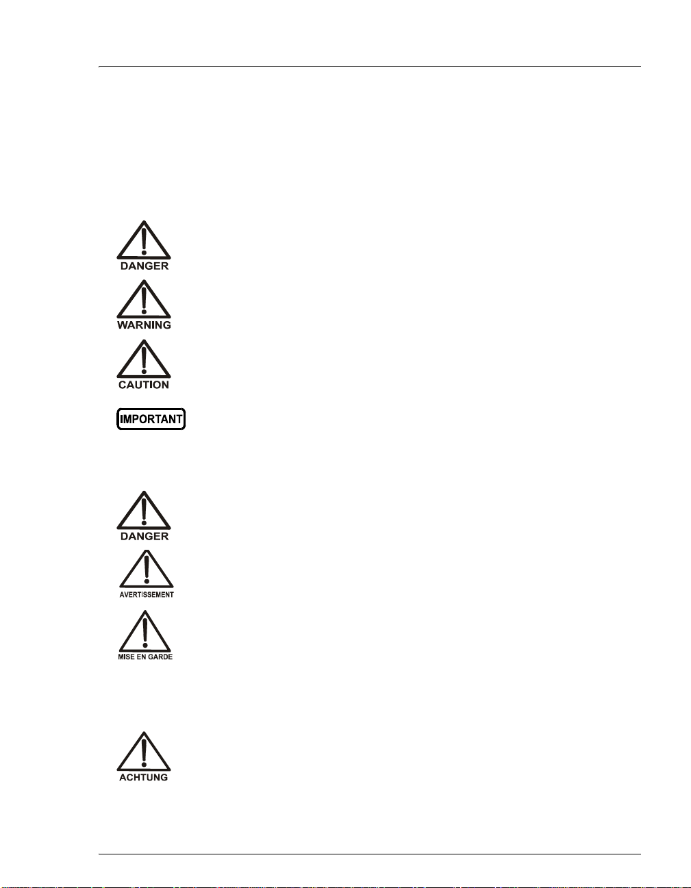
1.2.1 Safety Messages and Notes
This manual contains warnings and precautionary statements that can
prevent personal injury and/or damage to the AS-HV when properly
followed. Safety messages appear in bold type and are accompanied by
icons, as shown below.
Indicates an imminently hazardous situation which, if not avoided, will
result in death or serious injury.
Indicates a potentially hazardous situation which, if not avoided, may
result in death or serious injury.
Indicates a potentially hazardous situation which, if not avoided, may
result in minor or moderate injury.
Indicates that the function or process of the instrument may be
impaired. Operation does not constitute a hazard.
1 • Introduction
Messages d’avertissement en français
Signale une situation de danger immédiat qui, si elle n'est pas évitée,
entraînera des blessures graves à mortelles.
Signale une situation de danger potentiel qui, si elle n'est pas évitée,
pourrait entraîner des blessures graves à mortelles.
Signale une situation de danger potentiel qui, si elle n'est pas évitée,
pourrait entraîner des blessures mineures à modérées. Également
utilisé pour signaler une situation ou une pratique qui pourrait
gravement endommager l'instrument mais qui n'entraînera pas de
blessures.
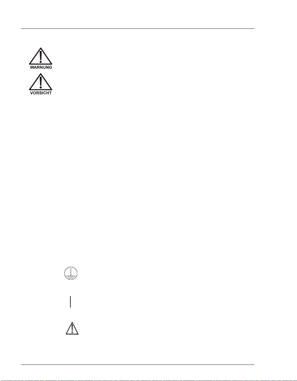
Warnhinweise in Deutsch
Bedeutet unmittelbare Gefahr. Mißachtung kann zum Tod oder
schwerwiegenden Verletzungen führen.
Doc. 065125-01 10/06 3
Page 12
AS-HV Operator’s Manual
Bedeutet eine mögliche Gefährdung. Mißachtung kann zum Tod oder
schwerwiegenden Ve rletzungen führen.
Bedeutet eine mögliche Gefährdung. Mißachtung kann zu kleineren
oder mittelschweren Verletzungen führen. Wird auch verwendet, wenn
eine Situation zu schweren Schäden am Gerät führen kann, jedoch
keine Verletzungsgefahr besteht.
Informational messages also appear throughout this manual. These are
labeled NOTE and are in bold type:
NOTE NOTES call attention to certain information. They alert
the user to an unexpected result of an action, suggest
how to optimize instrument performance, etc.
1.3 Safety Labels
The TUV GS and cTUVus Mark safety labels and the CE Mark label on the ASHV indicate that the AS-HV is in compliance with the following standards and
directives: EN 61010-1:2001 (safety), CAN/CSA-C22.2 No. 61010-1:2004
(safety), UL 61010-1:2004 (safety), EN 61326 1997 + A1:1998 + A2:2001
(EMC), Low-Voltage Equipment Directive 73/23/EEC, and EMC Directive
89/336/EEC.
These symbols appear on the AS-HV or on AS-HV labels:
Alternating current
˜
Protective conductor terminal
Power supply is on
Indicates a potential hazard. Refer to the operator’s manual for
an explanation of the hazard and how to proceed.
4 Doc. 065125-01 10/06
Page 13
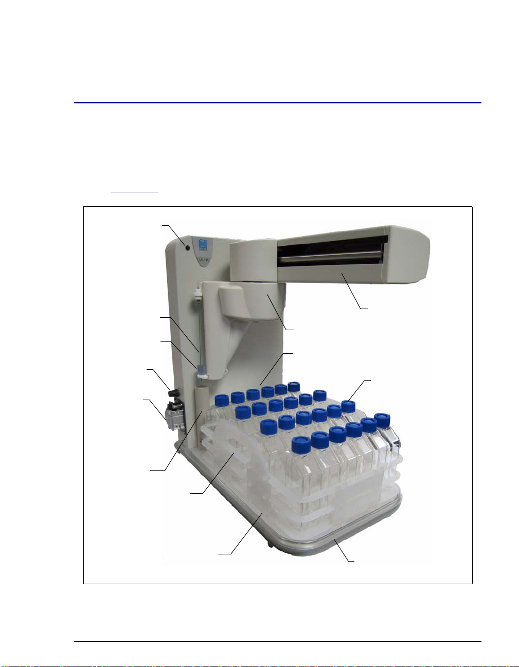
2.1 AS-HV Overview
Figure 2-1 is an overview of the main features of the AS-HV Autosampler.
Power
LED
Sampling Needle
Sampling Needle
Guide
Rinse Pump
Speed Knob
Rinse Pump
2 • Description
Sampling Arm
Support
Sampling Arm
Standards Rack
Nunclon Sample
Flasks
Fixed Rinse
Reservoir
Sample Rack
Rack Location Mat
Base Support Tube
Figure 2-1. AS-HV Autosampler
Doc. 065125-01 10/06 5
Page 14

AS-HV Operator’s Manual
Power LED
The power LED lights when power to the AS-HV is turned on, and should remain
lit as long as the main power supply is operational. If the LED fails to light when
the power is turned on, refer to Section 4.4
NOTE The power switch is located on the AS-HV side panel
(see Section 2.2
Sample Rack
The sample rack houses the sample containers. The AS-HV is shipped with a 24position sample rack (P/N 064233) designed to accommodate 250 mL Nunclon
sample flasks (flasks: P/N 064053, pkg. of 50; caps and septa: P/N 064235; pkg.
of 50).
All sample container caps contain a split septum that allows the PEEK sampling
needle to pierce the cap, while also maintaining sample integrity and minimizing
sample evaporation.
Optional: A 15-position sample rack (P/N 064234) that accommodates 250 mL
narrow-mouth Nalgene® bottles (bottles: P/N 064236, pkg. of 72; caps and septa:
P/N 064232, pkg. of 72).
for troubleshooting help.
).
Rack Location Mat
The rack location mat (P/N 064250) is mounted on the spill tray. The mat houses
the sample rack and provides calibration coordinates for properly aligning the
sampling needle over a sample container.
Spill Tray
The spill tray (P/N 064251) provides secondary containment for sample
containers in the autosampler.
Standards Rack
Standards and/or samples can be loaded onto the standards rack. The AS-HV is
shipped with an 11-position standards rack (P/N 064253).
Optional: A 6-position standards rack (P/N 064252).
6 Doc. 065125-01 10/06
Page 15

2 • Description
Sampling Needle
The sampling needle is used to aspirate sample from sample containers.
The AS-HV is shipped with a PEEK Sampling Needle Kit (P/N 064511). The kit
includes the sampling needle (a piece of specially pre-bent 0.8-mm (0.030-in) ID
PEEK tubing), fittings, and mounting hardware.
The PEEK tubing is not only the sampling needle, but the point at which the
sample is introduced to the IC. This transfer mechanism minimizes contamination
that can be caused by fittings, extra tubing, and manual sample handling.
Optional: A Sampling Needle Kit–PTFE Lined and Sleeved (P/N 064056)
containing a stainless steel needle that is lined and sleeved with PTFE
(polytetrafluoroethylene).
Sampling Needle Guide
The AS-HV is shipped with a sampling needle guide (P/N 064519). The guide
serves two purposes:
• To ensure that the PEEK sampling needle does not bend or flex as it pierces
the septum in the sample container cap.
• To ensure that the sample container is not lifted out of the sample rack during
sampling.
Rinse Station
The rinse station cleans the sampling needle between samples. During the
cleaning cycle, the needle is inserted into the rinse fluid, fluid is drawn and then
dispensed through the needle, and the dispensed fluid is directed to waste. The
rinse station consists of:
• A 150 mm reservoir of rinse fluid. Dionex recommends using ASTM Type I
(or better) filtered, deionized water as the rinse fluid.
• A variable-speed peristaltic pump that provides a supply of fresh rinse fluid to
the reservoir. The potentiometer knob fitted above the pump is used to adjust
the flow rate (see Section 3.2.3
If an external rinse source is available, the reservoir can be connected directly to
this source and the peristaltic pump can be replumbed for operation as the sample
loading pump. For more information, refer to Section 2.4.4
).
.
Doc. 065125-01 10/06 7
Page 16
AS-HV Operator’s Manual
2.2 AS-HV Side Panel
This section describes (from top to bottom) the components located on the right
side panel of the AS-HV.
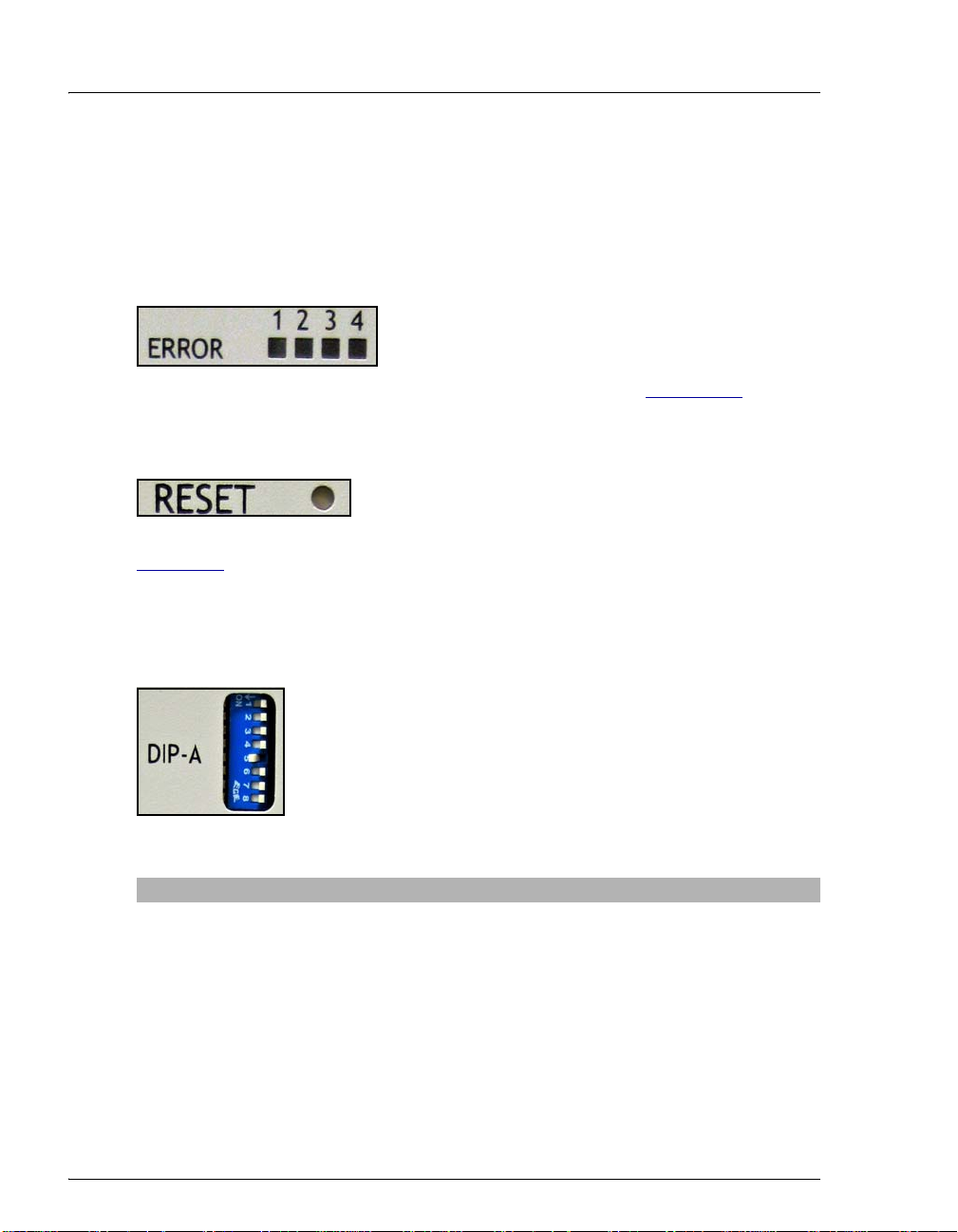
ERROR Indicators
that Error 6 (an X-axis position error) has occurred. Refer to Section C.2
explanation of all of the error codes.
RESET Switch
problems with autosampler movement in the X-, Theta-, and Z-axes (see
Figure 3-1
motors operate and the action of the carriages is correct.
A small pointed device is required to depress the recessed switch.
). Successful completion of the reset procedure confirms that the
If a fault occurs, the ERROR indicators light to
display a binary error code (in blue) that identifies
the fault. For example, the error code 0110 indicates
for an
Pressing the RESET switch returns the AS-HV to its
initial start-up sequence. The reset procedure identifies
DIP-A DIP Switches
The DIP switches are numbered 1 to 8 (from top to bottom).
SW5 sets the baud rate (the only communication parameter
that can be set on the AS-HV).
The table below lists the DIP switch functions and default
settings. The switch positions are indicated as 0 = Off
(Up/Open) or 1= On (Down/Closed).
DIP Switch Default Setting Description
SW1 Off Self-test mode
SW2 Off Reserved
SW3 Off Reserved
SW4 Off Reserved
SW5 On Baud rate
SW6 Off Mode selection
SW7 Off Mobile rinse station expiration timer
SW8 Off Wash select MRS/FWR (mobile rinse
station/fixed rinse reservoir)
8 Doc. 065125-01 10/06
Page 17
2 • Description
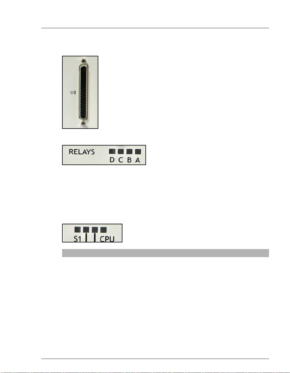
I/O Port
The I/O port provides eight contact closure inputs and four relay
outputs.
The autosampler has four internal relays (A, B, C, and D).
Normally open and normally closed contact pairs are available on
the external I/O connector.
Relay A is reserved for control of the internal peristaltic pump.
Relay B is reserved for control of an external relay-controlled
pump operating as the sample loading pump. The relays can be
controlled through commands programmed in Chromeleon.
RELAY Status Indicators
These indicators light (yellow) to indicate the
state of the internal relays (A, B, C, and D).
When a relay is energized, the corresponding
indicator is lit.
The relay outputs can be used to connect and control low power devices. These
outputs should be limited to loads of 1 amp or less. The eight digital inputs
available on the autosampler allow monitoring of electrical signals between 0 and
+24 volts.
System Status Indicators
These indicators light (yellow) to identify certain
autosampler conditions. For details, see the table below.
.
Status Indicator Description Indication
S1 Programmable behavior
LED
AUX Auxiliary instrument port
activity LED
HOST Host interface port
activity LED
CPU Central processor unit
(CPU) activity LED
Doc. 065125-01 10/06 9
ON when programmed
ON when a byte is sent or received
on Auxiliary Instrument Port, then
OFF
ON when a byte is sent or received
on Host Interface Port, then OFF
OFF for 10 seconds, then ON for
1 second
Page 18
AS-HV Operator’s Manual
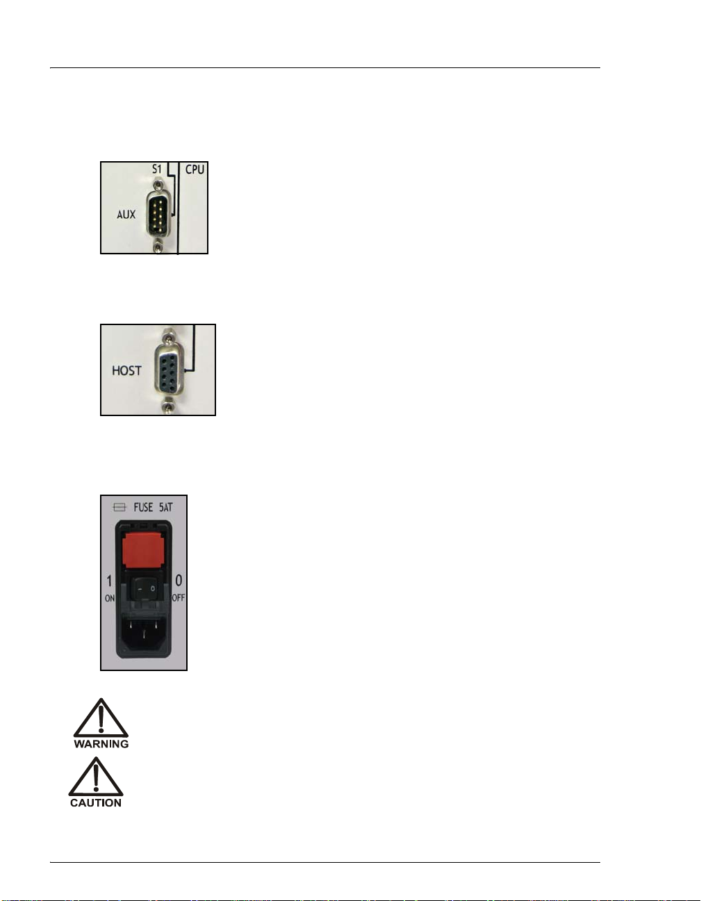
AUX (Auxiliary Communications) Port
The AUX port provides a standard RS-232 interface connection
from the AS-HV to the optional syringe pump or AXP pump.
The port supports a baud rate of 9600 and operates as
connected DCE (Data Computer Equipment); the pumps
operate as DTE (Data Terminal Equipment). The RS-232 cable
required to connect the pump to the
the pump Ship Kit.
HOST (Host Communications) Port
The HOST port provides a connection from the AS-HV to a
serial port on the Chromeleon PC. The AS-HV Ship Kit
(P/N 064051) includes an RS-232 cable (P/N 060683) for this
connection.
If a serial port is not available on the PC, order the optional
RS-232-to-USB cable (P/N 064261) and use this cable to
connect the autosampler to a USB port on the PC.
AUX port is provided in
Power Entry
SHOCK HAZARD—To avoid electrical shock, use a grounded
receptacle. Do not operate the AS-HV or connect it to AC power mains
without an earthed ground connection.
The power supply cord is used as the main disconnec t device. Make
sure the socket-outlet is located near the AS-HV and is easily
accessible.
The power entry incorporates the AS-HV main power switch and
the fuse compartment.
The AS-HV operates from input voltages over a range of 100 to
240 VAC, 50 to 60 Hz power, and requires a grounded, singlephase power source. The typical input power is 75 W and the
maximum line draw is 1.8 amps at 110 VAC (when the power is
turned on). The appropriate line voltage and frequency are
selected automatically.
10 Doc. 065125-01 10/06
Page 19
2 • Description
Operation at AC input levels outside of the specified operating voltage
range may damage the AS-HV.
DANGER D'ÉLECTROCUTION—Pour éviter toute électrocution, il faut
utiliser une prise de courant avec prise de terre. Ne l'utilisez pas et ne
le branchez pas au secteur C.A. sans utiliser de branchemen t mis à la
terre.
Le cordon d'alimentation principal est utilisé comme dispositif
principal de débranchement. Veillez à ce que la prise de base soit
située/installée près du module et facilement accessible.
STROMSCHLAGGEFAHR—Zur Vermeidung von elektrischen
Schlägen ist eine geerdete Steckdose zu verwenden. Das Gerät d arf
nicht ohne Erdung betrieben bzw. an Wechselstrom angeschlossen
werden.
Das Netzkabel ist das wichtigste Mittel zur Stromunterbrechung.
Stellen Sie sicher, daß sich die Steckdose nahe am Gerät befindet und
leicht zugänglich ist.
DANGER D'ÉLECTROCUTION—Pour éviter toute électrocution, il faut
utiliser une prise de courant avec prise de terre. Ne l'utilisez pas et ne
le branchez pas au secteur C.A. sans utiliser de branchemen t mis à la
terre.
Le cordon d'alimentation principal est utilisé comme dispositif
principal de débranchement. Veillez à ce que la prise de base soit
située/installée près du module et facilement accessible.
Fuse Compartment
The fuse compartment contains two slow-blow fuses rated at 5 amps
(P/N 064248). For instructions on how to replace the fuses, refer to Section 5.5
For continued protection against risk of fire or shock, replacement
fuses must be the type and rating specified in this manual.
Doc. 065125-01 10/06 11
.
Page 20
AS-HV Operator’s Manual
Pour maintenir la protection contre les risques d'incendie ou
d'électrocution, remplacez toujours les fusibles par des fusibles du
même type et du même calibre.
Zum Schutz vor Feuer und Stromschlägen müssen beim
Sicherungswechsel immer Sicherungen des gleichen Typs und mit
gleicher Leistung verwendet werden.
2.3 Sample Loading Modes
The AS-HV supports two sample loading modes:
• In the push mode, sample enters the sample loading pump and is then pushed
into the sample loop or concentrator column.
• In the pull mode, sample is pulled into the sample loop or concentrator
column via the sample loading pump.
The sample loading mode is determined by the components that are installed and
the plumbing connections; for schematics showing typical configurations, refer to
Appendix B
.
Sample Overlap
To reduce the time between injections, some Dionex devices, including the ASHV, support overlapping sample preparation. This means that, while data
collection and analysis for the current sample are still in progress, the AS-HV can
perform sample preparation steps for the next sample. When the autosampler
finishes the overlapped functions, the Chromeleon program waits, if necessary , to
finish the currently running sample. Then, the remaining commands in the
overlapped sample's program are executed.
Sample overlap is enabled in the Chromeleon Program Wizard (see Section 3.2.4
12 Doc. 065125-01 10/06
).
Page 21

2.4 Sample Loading Pumps
This section provides a brief overview of the sample loading pump options for the
AS-HV:
• A syringe pump (see Section 2.4.1)
• A single-piston pump—the AXP Pump (see Section 2.4.2)
• An external peristaltic pump—the MASTERFLEX® C/L® Pump System
(see Section 2.4.3
• An internal peristaltic pump (see Section 2.4.4)
• A relay-controlled pump (see Section 2.4.5)
2.4.1 Syringe Pump
The syringe pump (P/N 064506) contains a stepper-motor driven syringe
and a three-way distribution valve to aspirate and dispense measured
quantities of liquid. A control cable connects the syringe pump to the
AUX and I/O ports on the AS-HV side panel (see Section 2.2).
)
2 • Description
When coupled with the syringe pump, the AS-HV is capable of both
concentrator and loop loading in the push or pull mode (see Section 2.3
This configuration provides maximum flexibility in terms of Chromeleon
control and flow precision.
T o ensure optimal performance when doing concen trator loading with the
syringe pump, follow these guidelines:
).
• All points in the system that will be aspi rated should be plumbed with
1.0-mm (0.040-in) ID PEEK tubing (P/N 054410).
• Push mode only: Dionex does not recommend using the push mode
with the syringe pump. If you do use the push mode, make sure the
backpressure does not exceed 0.41 MPa (60 psi).
• Pull mode only: If the Dionex TCC-XLP1 concentrator column is
installed, the maximum flow rate is 0.5 mL/min and the backpressure
should not exceed 0.10 MPa (15 psi).
• Pull mode only: If the Dionex UTAC-XLP1 concentrator column is
installed, the maximum flow rate is 1.0 mL/min and the backpressure
should not exceed 0.10 MPa (15 psi).
Doc. 065125-01 10/06 13
Page 22

AS-HV Operator’s Manual
2.4.2 AXP Pump
The single-piston AXP pump (P/N 064507) can deliver from 0.01 to
10.00 mL/min of a single solution or eluent. A serial cable connects the
AXP pump to the
The AXP pump is controlled via Chromeleon.
When coupled with the AXP pump, the AS-HV is capable of concentrator
and sample loop loading in the push or pull mode (see Section 2.3
users may prefer to configure the pump as a “pull” device in order to
minimize the contamination that can result when the sample comes into
contact with check valves and seals.
However, Dionex does not recommend using the pull mode for
concentrator loading. Piston pumps can cavitate and lose prime unless
there is a continuous flow of liquid through the pump. With the AXP
pump, these problems are most likely to occur when performing
concentrator loading in the pull mode.
T o ensure op timal performance when doi ng concentrator loadin g with the
AXP pump, follow these guidelines:
AUX port on the AS-HV side panel (see Section 2.2).
). Some
• Any Dionex concentrator column (or guard column used as a
concentrator column) may be installed for loading in the push mode.
Select the flow rate recommended for your concentrator column. All
points in the system that will be aspirated should be plumbed with
1.0-mm (0.040-in) ID PEEK tubing (P/N 054410).
When doing sample loop loading with the AXP pump, follow these
guidelines:
• Pull mode only: The maximum flow rate is 0.75 mL/min. The
backpressure should not exceed 0.07 MPa (10 psi).
NOTE An electronic copy of the AXP/AXP-MS Metering
Pump Operator’s Manual (Document No. 031897) is
provided on the Dionex Reference Library CDROM. Before beginning operation with the pump,
familiarize yourself with the content of the manual.
14 Doc. 065125-01 10/06
Page 23

2.4.3 External Peristaltic Pump
The external peristaltic pump (P/N 064508) is a MASTERFLEX C/L
Pump System. A relay cable connects the AS-HV to the terminal strip on
the pump’s rear panel.
When coupled with the external peristaltic pump, the AS-HV is capable
of sample loop loading in either the push or pull mode (see Section 2.3
This configuration is typically used to load sample when a large sample
loop is installed.
NOTE To minimize potential sample contamination,
Dionex recommends using the pull mode with the
external peristaltic pump.
T o ensure optimal performance when doing loop loading with the external
peristaltic pump, follow these guidelines:
• All points in the system that will be aspi rated should be plumbed with
1.0-mm (0.040-in) ID PEEK tubing (P/N 054410).
• To ensure that the proper sample volume is loaded, measure the flow
rate after replacing any component in the flow path. It is advisable to
measure the flow rate periodically, as flow rates may fluctuate over
time as the columns and peristaltic pump tubing age.
2 • Description
).
• Push mode only: The backpressure should not exceed 0.10 MPa
(15 psi).
• Pull mode only: The maximum flow rate is 1.75 mL/min. The
backpressure should not exceed 0.07 MPa (10 psi).
NOTE A printed copy of the MASTERFLEX C/L Pump
System Operator’s Manual is shipped with the pump.
Before beginning operation with the pump,
familiarize yourself with the content of the manual.
Doc. 065125-01 10/06 15
Page 24

AS-HV Operator’s Manual
2.4.4 Internal Peristaltic Pump
The AS-HV rinse station includes a built-in peristaltic pump that provides
a supply of fresh rinse fluid to the reservoir (see page 7
controlled through Relay A.
If the rinse station is connected directly to an external rinse source, the
peristaltic pump can be replumbed for use as the sample loading pump in
either the push or pull mode (see Section 2.3
instructions, refer to Section B.3.12
To ensure optimal performance when using the internal peristaltic pump
for sample loading, the delivery pressure should be less than 0.03 MPa
(5 psi).
2.4.5 Relay-Controlled Pump
An external relay-controlled pump from a third-party vendor can be used
for sample loading in either the push or pull mode (see Section 2.3
pump is controlled through Relay B.
). The pump is
). For replumbing
.
). The
A relay cable connects the pump to the
(see Section 2.2
although only through relay control.
If you have a question regarding the use of third-party pumps with th e
AS-HV, please contact Dionex. In the U.S., call 1-800-346-6390 and
select the Technical Support option. Outside the U.S., call the nearest
Dionex office.
). Note that the pump is supported by Chromeleon,
I/O port on the AS-HV side panel
16 Doc. 065125-01 10/06
Page 25

2.5 Chromeleon Software
Chromeleon software is required for control of AS-HV operation. Two modes of
software control are available: direct control and automated control.
• With direct control, the user selects operating parameters and commands from
the Chromeleon menu bar, toolbars, and AS-HV Control panels. Direct
control commands are executed as soon as they are entered.
• With automated control, the user creates a program (sometimes called a PGM
file) that contains a list of commands that will be performed at specified times
for automated operation of the AS-HV. You can create program files
automatically , using the Program Wizard, or manually, by modifying an
existing program.
In addition to general commands for device control, Chromeleon includes many
commands specifically for the AS-HV and the sample loading pumps (see
Table 2-1
You can select these commands from the default Control panel or the Commands
dialog box. To open the dialog box, press F8 or select Control > Command.
through Table 2-4).
2 • Description
Command Function
FlushAspirateSpeed* Specifies the speed at which the sampling needle is
filled with rinse fluid.
RinseVolume Specifies the volume of rinse fluid used to wash the
sampling needle.
SampleAspirateSpeed* Specifies the speed at which the syringe draws sample
from the sample container.
SyringeAspirate The syringe pump aspirates the specified volume of
liquid through the sampling needle.
SyringeDispense The syringe pump dispenses the specified volume of
liquid through the sampling needle.
SyringeReset Resets the syringe pump to the initial position.
SyringeSize Reports the volume of the syringe (read-only).
SyrPumpPosition Reports the position of the syringe pump plunger
(read-only).
SyrPumpStatus Reports whether the syringe pump is busy and whether
an error condition has been detected (read-only).
Table 2-1. Chromeleon Commands for the Syringe Pump
Doc. 065125-01 10/06 17
Page 26

AS-HV Operator’s Manual
Command Function
ValvePosition Sets the position of the distribution valve in the syringe
WashPortDispenseSpeed* Specifies the speed at which rinse fluid is dispensed
WasteDispenseSpeed* Specifies the speed at which liquid is directed to waste.
* There are six syringe speeds, and each speed has 10 levels. The flow rate varies,
depending on the command and the speed setting. For details, refer to the tables in
“
Sampler Options Screen: Syringe Pump Version” on page 27.
Table 2-1. Chromeleon Commands for the Syringe Pump (Continued)
Command Function
AxpCurrentSetup Reports the AXP pump configuration and the status of
AxpState Turns the AXP pump on and off.
Flow Sets the flow rate for the AXP pump.
Pressure.LowerLimit* Sets the lower pressure limit for the AXP pump.
Pressure.UpperLimit* Sets the upper pressure limit for the AXP pump.
Pressure.Value* Reports the current AXP pump pressure (read-only).
RinseVolume Specifies the volume of rinse fluid used to wash the
* To display this command, click the plus sign beside the Pressure command.
pump.
through the sampling needle.
several operating parameters (read-only). To view
details, click the plus sign beside this command.
sample loop, sampling needle, and sample loading
path.
Table 2-2. Chromeleon Commands for the AXP Pump
18 Doc. 065125-01 10/06
Page 27

2 • Description
Command Function
InternalPumpOff* Turns off the internal peristaltic pump.
InternalPumpOn* Turns on the internal peristaltic pump.
IntPumpDirection* Specifies the direction of operation for the internal
peristaltic pump.
Flow Sets the flow rate of the internal peristaltic pump.
RinseVolume Specifies the volume of rinse fluid used to wash the
sample loop, sampling needle, and sample loading
path.
* This command is not available unless the internal peristaltic pump is selected as the
Sample Loading Pump in the AS-HV Properties dialog box (see Section B.3.16
Table 2-3. Chromeleon Commands for the Internal Peristaltic Pump
Command Function
Flow Sets the flow rate of the relay-controlled pump.
RinseVolume Specifies the volume of rinse fluid used to wash the
sample loop, sampling needle, and sample loading
path.
).
Table 2-4. Chromeleon Commands for the Relay-Controlled Pump
Doc. 065125-01 10/06 19
Page 28

AS-HV Operator’s Manual
20 Doc. 065125-01 10/06
Page 29
3 • Operation and Maintenance
The AS-HV Autosampler is designed for use with IC (ion chromatography) and
HPLC (high-performance liquid chromatography) systems and should not be used
for any other purpose. Operation of the AS-HV in a manner not specified by
Dionex may result in personal injury.
If you have a question regarding appropriate usage, please contact Dionex before
proceeding. In the U.S., call 1-800-346-6390 and select the Technical Support
option. Outside the U.S., call the nearest Dionex office.
3.1 Safety Guidelines
SHOCK HAZARD—To avoid electrical shock, use a grounded
receptacle. Do not operate the AS-HV or connect it to AC power mains
without an earthed ground connection.
The power supply cord is used as the main disconnect device. Make
sure the socket-outlet is located near the AS-HV and is easily
accessible.
Operation at AC input levels outside of the specified operating voltage
range may damage the AS-HV.
DANGER D'ÉLECTROCUTION—Pour éviter toute électrocution, il faut
utiliser une prise de courant avec prise de terre. Ne l'utilisez pas et ne
le branchez pas au secteur C.A. sans utiliser de branchemen t mis à la
terre.
Le cordon d'alimentation principal est utilisé comme dispositif
principal de débranchement. Veillez à ce que la prise de base soit
située/installée près du module et facilement accessible.
STROMSCHLAGGEFAHR—Zur Vermeidung von elektrischen
Schlägen ist eine geerdete Steckdose zu verwenden. Das Gerät d arf
nicht ohne Erdung betrieben bzw. an Wechselstrom angeschlossen
werden.
Doc. 065125-01 10/06 21
Page 30
AS-HV Operator’s Manual
Das Netzkabel ist das wichtigste Mittel zur Stromunterbrechung.
Stellen Sie sicher, daß sich die Steckdose nahe am Gerät befindet und
leicht zugänglich ist.
• Always stay clear o f the sampling arm during operation. Al though the AS-HV
is designed to stop running as soon as the arm encounters an obstruction, the
arm can move fast and injury may occur if a user is struck. For added
protection, place the optional Plexiglas
over the autosampler (see Section B.3.7
To avoid injury, always maintain a safe distance from the sampling
arm during operation.
Afin d'éviter toute blessure, maintenez vous toujours à distance de
sécurité du bras robotique pendant son déplacement.
Um Verletzungen zu vermeiden, behalten Sie immer eine sichere
Entfernung vom Probenarm während Betriebs bei.
® trace analysis cover (P/N 064052)
).
3.2 Getting Ready to Run
3.2.1 Filling Sample Containers and Loading the Racks
1. Fill the Nunclon sample flasks (P/N 064053, pkg. of 50) or Nalgene
bottles (P/N 064236, pkg. of 72) with sample.
2. Install the caps and septa (Nunclon sample flask caps and septa:
P/N 064235, pkg. of 50; Nalgene bottle caps and septa: P/N 064232,
pkg. of 72) as follows:
a. Turn one of the sample container caps upside down. Place a
septum, white side facing down, in the cap. Push the septum fully
into the cap. (This prevents the septum from falling into the
sample container when pierced by the sampling needle.)
b. Repeat Step a
22 Doc. 065125-01 10/06
for the required number of caps.
Page 31

c. Place the caps on the sample containers. After checking that the
white side of the septum faces up, tighten each cap loosely.
Overtightening the caps may twist the septa, making them
unusable.
3. Load the sample containers into the sample rack and/or standards
rack in the order required for the application.
3.2.2 Turning On the Power
1. Turn on the AS-HV main power switch.
At power-up, the AS-HV automatically begins an initialization
sequence in which the sampling needle moves through the extent of
the autosampler’s working envelope. Upon completing the
initialization sequence, the needle returns to the home position above
the fixed rinse reservoir. During initialization (see Figure 3-1
• The needle raises to the full extremes of the Z-axis.
• The needle travels to the full extremes of the X-axis.
3 • Operation and Maintenance
):
• The needle travels to the full extremes of the Theta-axis.
If the sampling needle fails to initialize successfully, refer to
Section 4.3 for troubleshooting assistance.
Theta-Axis
Z-Axis
Figure 3-1. Mechanical Axes
X-Axis
Doc. 065125-01 10/06 23
Page 32

AS-HV Operator’s Manual
3.2.3 Selecting the Rinse Pump Speed
Use the potentiometer knob above the
rinse pump to set the flow rate for the
application (see Figure 3-2
The default speed is nominally set to
obtain a minimum speed of 40 rpm and
a maximum of 100 rpm.
When pumping viscous fluids, run at a
slow speed.
).
Pump Speed
Control Knob
Rinse Pump
Figure 3-2. Rinse Pump Speed Control Knob
NOTE When the rinse pump is not in use, release the track
occlusion arm; this will extend the life of the bridge
tubing (see Figure B-4
).
24 Doc. 065125-01 10/06
Page 33

3 • Operation and Maintenance
3.2.4 Creating a Chromeleon Program
A Chromeleon program (sometimes called a PGM file) is a list of control
commands—to be executed at specified times—created by the user for
automated operation of the AS-HV. There are two ways to create
programs:
• Automatically, using the Program Wizard
• Manually, by modifying an existing program
This section provides an overview of how to create a program with the
Program Wizard. For detailed instructions, refer to the Chromeleon Help
or user’s guide.
To create a program:
1. Start the Chromeleon Server, if it is not already running:
If the Chromeleon Server icon on the Windows taskbar is crossed out
in red , the Server is not running. Start the Server by right-
clicking the icon and selecting Start Server. When the server is
running, the icon is gray .
If the Server Monitor icon is not on the taskbar, click Start on the
taskbar and select All Programs (or Programs, depending on the
operating system) > Chromeleon > Server Monitor. Click Start to
start the server.
2. To start the Chromeleon client, click Start on the Windows taskbar
and select All Programs (or Programs) > Chromeleon >
Chromeleon.
3. Select File > New.
A dialog box appears.
4. Select Program File and click OK.
Doc. 065125-01 10/06 25
Page 34

AS-HV Operator’s Manual
The initial Program Wizard screen is displayed.
5. Select the Timebase where the program will run.
6. Click Next to continue.
If the selected timebase includes other devices, Program Wizard
screens for these devices are displayed before the AS-HV screens. On
each screen, select the required parameters and click Next until the
Sampler Options screen is displayed.
7. There are three versions of the Sampler Options screen. The version
that appears now depends on the sample loading pump selected in the
Server Configuration (see Section B.3.16
All versions of the Sampler Options screen include the Needle
Height control and the Options group box. In addition, each screen
includes a group box with special controls for the selected pump.
26 Doc. 065125-01 10/06
).
Page 35

3 • Operation and Maintenance
Sampler Options Screen: Syringe Pump Version
When the sample loading pump is the syringe pump , this screen is
displayed:
Select the Needle Height.
Select the Rinse Volume.
Select the syringe speed for the remaining parameters in the Syringe
Pump group box. There are two syringe speeds (fast and slow), and
each speed has 10 levels. The actual speed depends on multiple
factors; for details, refer to the following sections.
“Fast” Syringe Speed
The syringe operates at the “fast” speed for Aspirate Speed from
Flush Bottle and Dispense Speed to Waste Bottle (see Table 3-1)
.
In the default AS-HV configuration, liquid moves through large bore
tubing during these operations. When selecting a speed setting, be
sure to take into account the tubing bore.
Doc. 065125-01 10/06 27
Page 36

AS-HV Operator’s Manual
.
Table 3-1. “Fast” Syringe Speed Settings
Speed Setting Top Speed
(steps/sec)
Flow Rate
(mL/min)
1 800 10.0
2 1200 15.0
3 1600 20.0
4 2000 25.0
5 2400 30.0
6 2800 35.0
7 3200 40.0
8 3600 45.0
9 4000 50.0
10 4800 60.0
“Slow” Syringe Speed
The syringe operates at the “slow” speed for Dispense Speed to
Wash Port and Aspirate Speed from Sample Container. The actual
speed depends on the parameter, the speed setting, the sample loading
type, and the sample loading mode (see Table 3-4
for an overview).
In the default AS-HV configuration, liquid moves through smaller
bore tubing during these operations. When selecting a speed setting,
be sure to take into account the tubing bore.
Table 3-2. Overview of “Slow” Syringe Speed Settings
Sample Loading Type/
Sample Loading Mode
Sample loop/Push See Table 3-3 See Table 3-4
Sample loop/Pull See Table 3-3 See Table 3-4
Concentrator column/
Push
Concentrator column/
Pull
28 Doc. 065125-01 10/06
Dispense Speed to
Was h Port
Aspirate Speed from
Sample Container
See Table 3-4 See Table 3-4
See Table 3-5 See Table 3-6
Page 37

3 • Operation and Maintenance
Table 3-3. “Slow” Syringe Speed Settings: Wash Port Dispense
Speed for Sample Loop/Push or Pull Mode
Speed Setting Top Speed
(steps/sec)
Flow Rate
(mL/min)
1801.00
2 160 2.00
3 200 2.50
4 240 3.00
5 280 3.50
6 320 4.00
7 360 4.50
8 400 5.00
9 440 5.50
10 480 6.00
Table 3-4. “Slow” Syringe Speed Settings: Sample Aspirate Speed
for Sample Loop/Push or Pull Mode or Concentrator Column/Push
Mode
Speed Setting Top Speed
(steps/sec)
Flow Rate
(mL/min)
1320.40
2640.80
3961.20
4 128 1.60
5 160 2.00
6 192 2.40
7 224 2.80
8 256 3.20
9 288 3.60
10 320 4.00
Doc. 065125-01 10/06 29
Page 38

AS-HV Operator’s Manual
Table 3-5. “Slow” Syringe Speed Settings: Wash Port Dispense
Speed for Concentrator Column/Push or Pull Mode
Speed Setting Top Speed
(steps/sec)
Flow Rate
(mL/min)
1400.50
2801.00
3 100 1.25
4 120 1.50
5 140 1.75
6 160 2.00
7 180 2.25
8 200 2.50
9 220 2.75
10 240 3.00
Table 3-6. “Slow” Syringe Speed Settings: Sample Aspirate Speed
for Concentrator Column/Pull Mode
Speed Setting Top Speed
(steps/sec)
Flow Rate
(mL/min)
1 8 0.10
2160.20
3240.30
4320.40
5400.50
6480.60
7560.70
8640.80
9720.90
10 80 1.00
30 Doc. 065125-01 10/06
Page 39

3 • Operation and Maintenance
To enable control of the injection valve by another device in the
timebase, select the V alve Contr ol check box. When the check box is
selected, the following options are enabled:
• Load/Inject Valve Using: Select the injection valve or relay/TTL
device that will control sample loading and injection.
• Injection Duration: Specify for how long injection occurs. (This
setting is ignored unless you select Sample Loop as the sample
loading type in the Server Configuration (see Section B.3.16
NOTE For sample overlap programs, the Injection
Duration must be less than the Delay Before
Processing Next Sample (see below).
).
To enable sample overlap (see Section 2.3), select the Sample
Overlap check box. When the check box is selected, the following
option is enabled:
• Delay Before Processing Next Sample: Specify for how long
the Chromeleon program waits in order to finish the currently
running sample before executing the remaining commands in the
program.
Doc. 065125-01 10/06 31
Page 40

AS-HV Operator’s Manual
Sampler Options Screen: AXP Pump Version
When the sample loading pump is the AXP pump, this screen is
displayed:
Select the Needle Height.
Select the Rinse Volume.
In the AXP Pump group box:
• Select the Rinse Volume.
• Select the Flow Rate.
• Set the Low Pressure Limit. The maximum value is the current
upper pressure limit setting (in psi) minus 100; the minimum
value is 0.
• Set the High Pressure Limit. The maximum value is 3000; the
minimum value is the current lower pressure limit setting (in psi)
plus 100.
Select the desired settings in the Options group box; for details, refer
to page 31
32 Doc. 065125-01 10/06
.
Page 41

3 • Operation and Maintenance
Sampler Options Screen: Internal Peristaltic Pump or RelayControlled Pump Version
When the sample loading pump is either the internal peristaltic pump
or a relay-controlled pump, this screen is displayed:
Select the Needle Height.
Select the Rinse Volume.
In the Internal Peristaltic Pump/Relay-Controlled Pump group
box:
• Select the Rinse Volume.
• Select the Flow Rate.
Select the desired settings in the Options group box; for details, refer
to page 31
Doc. 065125-01 10/06 33
.
Page 42

AS-HV Operator’s Manual
8. When you finish selecting parameters on the Sampler Options
screen, click Next to continue.
The following screen is displayed.
NOTE If you have already selected these parameters on the
device page for a particular module, the list box on
the Relay and State Devices Options page already
contains this information. If you change any settings
here, Chromeleon will automatically copy the
changes to the appropriate device page.
9. The window on the left lists the devices in the selected timebase.
Select a device from the list, and then click the plus sign to the left of
the device name to view the device states.
34 Doc. 065125-01 10/06
Page 43

3 • Operation and Maintenance
10. Specify the State or Duration for the selected device:
• Clicking State specifies a simple switch command. Select Open
or Closed from the drop-down list box.
• Clicking a state description sets the device to the selected state
and lets you specify a Duration. Enter the duration of the
selected state in the edit box.
NOTE Relays A and B are reserved for internal use
and cannot be selected.
11. To add the following information to the list box, click Add:
• Retention Time value
• Name of the selected Device
• State or Duration value
Chromeleon will automatically organize all entries in the list box in
chronological order.
To remove an entry from the list box, select the entry and click
Delete. (All entries in the list box will automatically be reorganized.)
12. Click Next to continue.
Doc. 065125-01 10/06 35
Page 44

AS-HV Operator’s Manual
The following screen is displayed.
13. (Optional) Type a descriptive Title for the program.
14. Select one of the following options:
• To save the program without first reviewing it, select Save the
program immediately. Clicking Finish opens a dialog box in
which you can save the program.
• To review the program before saving it, select Review the
program in a new window. Clicking Finish opens the program
in the Program Editor. Use the Program Editor to review the
program and to manually edit it, if necessary. When you finish,
exit the Program Editor. This displays a prompt asking whether
the program should be saved; clicking Yes opens a dialog box in
which you can save the program.
36 Doc. 065125-01 10/06
Page 45

3.3 Routine Maintenance
This section describes routine maintenance procedures that the user can perform
for the AS-HV and the syringe pump. Any maintenance procedures for the ASHV and the syringe pump that are not described here must be performed by
Dionex personnel. For maintenance procedures for other sample loading pumps,
refer to the respective product manual.
To contact Dionex in the U.S., call 1-800-346-6390 and select the Technical
Support option. Outside the U.S., call the nearest Dionex office.
NOTE The AS-HV has no lubrication requirements. Do not
apply lubrication to the sampling arm or any other
components.
3.3.1 Daily Maintenance
• Wipe up all spills immediately, especially spills of corrosive liquids.
• Inspect the syringe pump for leaks, and correct any problems.
3 • Operation and Maintenance
• Flush the syringe pump thoroughly with distilled or deionized water
after each use and when the pump is not in use.
NOTE Do not allow the syringe pump to run dry for
more than a few cycles.
• Check for air bubbles in the syringe(s) and tubing and remove any
bubbles that appear (see Section B.3.17
).
• Replace the rinse fluid. Dionex recommends using ASTM Type I (or
better) filtered, deionized water as the rinse fluid.
• To ensure correct drainage, the end of the waste line should not be
submerged in waste liquid. Check the volume of liquid in the waste
container and empty when needed.
Neutralize acidic and caustic wastes before disposal. Dispose of all
wastes in accordance with local regulations.
Doc. 065125-01 10/06 37
Page 46

AS-HV Operator’s Manual
Neutralisez les déchets acides ou caustiques avant d e les jeter. Jetez
les déchets aux règlements locaux.
Neutralisieren Sie säurehaltige und ätzende Abfälle vor ihrer
Entsorgung. Entsorgen Sie alle Abfälle entsprechend den lokalen
Bestimmungen.
3.3.2 Weekly Maintenance
• Check the tubing connected to the internal peristaltic pump. If the
tubing is crimped or blocked, replace it (rinse line: 2.06-mm (0.08-in)
ID Santoprene® tubing, P/N 064521; sample line: 0.64-mm (0.03-in)
ID Santoprene tubing, P/N 064825). Crimped or blocked tubing can
cause unexpected changes in the flow rate.
3.3.3 Monthly Maintenance
• Clean the fluid path of the syringe pump to remove precipitates (for
example, salts) and eliminate bacterial growth. For instructions, see
Section 5.1
.
3.3.4 Periodic Maintenance
• Clean the AS-HV external covers, spill tray, rack location mat, and
accessories with a damp soft cloth and diluted mild detergent.
• When operating the syringe pump in the push mode, check the
backpressure to confirm that it is less than 0.41 MPa (60 psi). This
prevents damage to the distribution valve.
• Replace the syringe pump inlet and outlet tubing and valve as
required. The frequency of replacement will depend on the duty
cycle, fluids used, and instrument maintenance.
38 Doc. 065125-01 10/06
Page 47

This chapter is a guide to troubleshooting minor problems that may o ccur during
operation of the AS-HV Autosampler. Turn to the section of this chapter that best
describes the operating problem or symptom that you have observed. Each section
lists possible causes of the problem or symptom.
If necessary, refer to the following sections of this manual for more information:
• Section C.1 contains a description of error messages that may be reported by
Chromeleon software and details about how to troubleshoot them.
• Section C.2 contains a description of error codes that may be displayed by the
AS-HV
If you are unable to solve a problem by following the instructions here, contact
Dionex Technical Support. In the U.S., call 1-800-346-6390. Outside the U.S.,
call the nearest Dionex office.
ERROR indicators and details about how to troubleshoot them.
4.1 Liquid Leaks
4.1.1 Leaking Fitting
4 • Troubleshooting
Locate the source of the leak and tighten (or replace) the liquid line
connection. For tightening requirements, refer to Installation of Dionex
Liquid Line Fittings (Document No. 031432). The manual is on the
Dionex Reference Library CD-ROM (P/N 053891).
4.1.2 Leaking Syringe
Possible Causes:
• Cracked syringe
• Damaged seal
• Loose fitting
• Loose syringe
Doc. 065125-01 10/06 39
Page 48

AS-HV Operator’s Manual
Actions:
• Check for a crack in the syringe. If the syringe is cracked, it must be
replaced (see Section 5.2
• Check the seal for scratches, deformation, or other damage. If the seal
is damaged, the syringe must be replaced (see Section 5.2
• If the syringe is not cracked and the seal is
not damaged, check that the syringe is
tightened. To tighten, hold the syringe at
the top and bottom fittings and turn it
clockwise (as viewed from the top) (see
Figure 4-1
not overtighten.
). Tighten fingertight only; do
).
).
Figure 4-1. Tightening the Syringe
4.1.3 Leaking Waste Line (Fixed Rinse Reservoir)
• Check that the waste line is pushed tightly onto the drip tray fitting
and that it is not elevated at any point after it exits the AS-HV.
• Check that the waste line is not crimped or otherwise blocked.
• To ensure correct drainage, make sure the end of the waste line is not
submerged in waste liquid.
• Check the volume of liquid in the waste container; empty as needed.
Neutralize acidic and caustic wastes before disposal. Dispose of all
wastes in accordance with local regulations.
40 Doc. 065125-01 10/06
Page 49

Neutralisez les déchets acides ou caustiques avant d e les jeter. Jetez
les déchets aux règlements locaux.
Neutralisieren Sie säurehaltige und ätzende Abfälle vor ihrer
Entsorgung. Entsorgen Sie alle Abfälle entsprechend den lokalen
Bestimmungen.
4.2 Sampling Arm Jams
If the sampling arm becomes jammed, the following events occur:
• The AS-HV error control system locks the motor drive.
• The ERROR indicators on the AS-HV side panel display an error code (see
Table C-1)
• The error is reported to Chromeleon and recorded in the Audit Trail.
Corrective action:
.
4 • Troubleshooting
1. Initialize the AS-HV. (Turn off the power, wait 10 seconds, and turn on the
power again.)
2. If the autosampler initializes correctly but the sampling arm becomes jammed
again, check into these possible causes:
• The arm may have hit an obstacle while moving into position.
• The arm may have stopped because it failed to reach a position within
the defined limits of the intended position. (Movement errors of less
than 1 mm will cause a jam.)
• If the mechanical movement has so much excessive friction that the
arm has difficulty in moving, it will cause the drive to stop.
• The posit ion of the arm may ha ve been moved with out being actively
driven by the autosampler.
If you are unable to eliminate the cause of the jam, contact Dionex for
assistance.
Doc. 065125-01 10/06 41
Page 50

AS-HV Operator’s Manual
4.3 Initialization Sequence Fails
If the AS-HV fails to complete the initialization sequence by driving the sampling
arm (see Section 3.2.2
• The ERROR indicators on the AS-HV side panel display error code 0101 (see
Table C-1)
.
• The error is reported to Chromeleon and recorded in the Audit Trail.
Corrective action:
1. Turn off the AS-HV power.
To avoid injury, turn off the power to prevent the sampling arm from
inadvertently moving while you are manually checking each axis.
Afin d'éviter toute blessure par suite du déplacement inopiné du bras
robotique, couper l'alimentation secteur pendant le contrôle manuel
des axes.
), the following events occur:
Um Verletzungen zu vermeiden, schalten Sie das Gerät bitte immer
aus, während Sie die Achsen manuell überprüfen, damit sich der
Probenarm nicht unbeabsichtigt bewegt.
2. Check each axis (see Figure 3-1
) manually for correct travel to determine
whether there is any mechanical obstruction.
3. If you do not find any mechanical obstructions, turn on the A S-H V power. If
the autosampler again fails to initialize, contact Dionex for assistance.
42 Doc. 065125-01 10/06
Page 51

4.4 Power LED Fails to Light
To troubleshoot:
1. Initialize the AS-HV. (Turn off the power, wait 10 seconds, and turn on the
power again.)
2. If the AS-HV initializes but the power LED still fails to light, the indicator is
faulty and should be replaced. Contact Dionex for assistance.
If the AS-HV fails to initialize and the power LED still fails to light, the
power supply fuse may have blown or the internal power supply may be
faulty. Contact Dionex for assistance.
NOTE The AS-HV electronics cannot be serviced by the user.
All repairs of the electronics components must be
performed by Dionex personnel.
4.5 CPU Activity LED Fails to Light
4 • Troubleshooting
To troubleshoot:
1. Initialize the AS-HV. (Turn off the power, wait 10 seconds, and turn on the
power again.)
2. If the AS-HV initializes but the
CPU LED still fails to light, the indicator is
faulty and should be replaced. Contact Dionex for assistance.
If the AS-HV fails to initialize and the LED still fails to light, the internal
power supply or the main PC board may have malfunctioned. Co ntact Dionex
for assistance.
NOTE The AS-HV electronics cannot be serviced by the user.
All repairs of the electronics components must be
performed by Dionex personnel.
Doc. 065125-01 10/06 43
Page 52

AS-HV Operator’s Manual
4.6 Power Supply Fails
If the green power indicator on the front of the AS-HV and/or the system status
indicator LEDs on the AS-HV side panel fail to light when expected, it may
indicate that the AS-HV power supply is not operational.
Corrective action:
1. Check that the power cable is connected to the AS-HV power entry and that
the power switch is turned on.
2. Check the fuses. If a fuse is blown, replace both fuses with new 5 amp slowblow fuses (P/N 064248). For fuse replacement instructions, refer to
Section 5.5
For continued protection against risk of fire or shock, replacement
fuses must be the type and rating specified here.
Pour maintenir la protection contre les risques d'incendie ou
d'électrocution, remplacez toujours les fusibles par des fusibles du
même type et du même calibre.
.
Zum Schutz vor Feuer und Stromschlägen müssen beim
Sicherungswechsel immer Sicherungen des gleichen Typs und mit
gleicher Leistung verwendet werden.
3. If the autosampler still fails to power up, contact Dionex for assistance.
NOTE Access to the power supply unit and components
requires removal of the main housing. Do not attempt to
access these components. All repairs of the electronics
must be performed by Dionex personnel.
44 Doc. 065125-01 10/06
Page 53

4.7 Cavitation in the Syringe
Cavitation in the syringe may occur when the syringe pump is operating in the
pull mode.
To troubleshoot:
1. The flow rate may be too high. Reduce the flow rate.
2. The concentrator column may be plugged. Refer to the column manual for
troubleshooting assistance. Column manuals are provided on the Dionex
Reference Library CD-ROM (P/N 053891).
4 • Troubleshooting
Doc. 065125-01 10/06 45
Page 54

AS-HV Operator’s Manual
46 Doc. 065125-01 10/06
Page 55

5•Service
This chapter describes routine service procedures that the user can perform for the
AS-HV Autosampler and the syringe pump. All procedures for the AS-HV and
the syringe pump that are not described here must be performed by Dionex
personnel. (For service procedures for other sample loading pumps, refer to the
respective product manual.)
To contact Dionex in the U.S., call 1-800-346-6390 and select the Technical
Support option. Outside the U.S., call the nearest Dionex office.
NOTE All repairs of the AS-HV electronics must be performed
by Dionex personnel.
Before replacing any part, refer to the troubleshooting information in Section 4 to
isolate the cause of the problem.
Substituting non-Dionex parts may impair the performance of the ASHV, thereby voiding the product warranty. Refer to the warranty
statement in the Dionex Terms and Conditions for more information.
5.1 Cleaning the Syringe Pump
To remove precipitates (salts, etc.) and eliminate bacterial growth, clean the fluid
path of the syringe pump monthly.
1. Make a solution of 10% methanol (MeOH) by adding one part of MeOH to
nine parts of deionized water. Dionex recommends using ASTM Type I (or
better) filtered, deionized water.
2. Prime the pump with the 10% MeOH and allow the solution to remain in the
pump, with the syringe fully lowered, for 30 minutes.
3. After the 30-minute period, remove the reagent tubing from the 10% MeOH
solution and cycle all the fluid from the syringe and tubing into a waste
container.
4. Prime the pump a minimum of 10 cycles with distilled or deionized water.
Doc. 065125-01 10/06 47
Page 56

AS-HV Operator’s Manual
k
Val
5.2 Replacing the Sample Syringe
Follow the instructions here to install a new 10 mL syringe (P/N 064224) in the
syringe pump.
5.2.1 Removing the Existing Syringe
Refer to Figure 5-1 when removing the existing syringe.
1. Remove the liquid from the
syringe.
2. Remove the plunger lock
screw .
3. In Chromeleon, select
SyringeAspirate in the
Commands dialog box.
Select the maximum Volume
(i.e., the size of the installed
syringe) and click OK to
lower the plunger drive.
4. Unscrew the syringe from the
valve.
ve
Syringe
Remove the plunger loc
screw
Figure 5-1. Removing the Syringe
48 Doc. 065125-01 10/06
Page 57

5•Service
5.2.2 Filling the New Syringe and Removing Bubbles
Method A
1. Fill a container with isopropyl alcohol. Place the threaded end of the
syringe into the container and slowly pull liquid into the syringe.
2. If air bubbles are present, pull the syringe plunger up and then push
down rapidly with short movements to dislodge the bubbles. Repeat
until all bubbles are dislodged.
3. Draw a full syringe volume up by slowly pulling out the plunger.
4. Keep the syringe in the liquid and slowly push the syringe plunger
until the bubble(s) exit the syringe. Then, fill the syringe.
5. Remove the syringe from the liquid. While holding it vertically, push
a small amount of liquid out the top to make sure no air remains.
Method B
1. Fill a container with isopropyl alcohol. Place the threaded end of the
syringe into the container and slowly pull liquid into the syringe.
2. Remove the syringe from the liquid and hold it with the threaded end
up under a stream of deionized water.
3. Push the syringe plunger up and pull down until the bubbles are
removed.
Doc. 065125-01 10/06 49
Page 58

AS-HV Operator’s Manual
Val
w
5.2.3 Installing the New Syringe
Refer to Figure 5-2 when installing the new syringe.
1. Screw the new syringe into
the valve.
2. Pull the syringe plunger
down to the plunger holder
assembly.
3. Screw the syringe plunger
into place.
4. Slide the plunger lock screw
through the plunger buttons
and fasten to the carriage.
NOTE Make sure the
plunger lock screw is
securely tightened
and the plunger
button is free to move
on the plunger lock
screw.
ve
Syringe
Plunger Lock Scre
Figure 5-2. Installing the New Syringe
50 Doc. 065125-01 10/06
Page 59

5.2.4 Initializing the New Syringe
1. Turn off the AS-HV power,
wait 10 seconds, and turn on the
power again.
2. In Chromeleon, select
SyringeReset in the Commands
dialog box and click OK.
This moves the syringe plunger
down slightly, into its initial
position (see Figure 5-3
).
5•Service
Initial
Position
Figure 5-3. Initializing the New Syringe
Doc. 065125-01 10/06 51
Page 60

AS-HV Operator’s Manual
5.3 Replacing the Sampling Needle
5.3.1 Removing the Existing Sampling Needle
1. In Chromeleon, select NeedleHome in the Commands dialog box and
click OK.
2. Turn off the AS-HV power switch.
To avoid injury, always turn off the power to the AS-HV before
installing or removing the sampling needle.
Afin d'éviter toute blessure, couper impérativement l'alimentation
secteur avant d'installer ou de démonter l'aiguille de prélèvement.
Um Verletzungen zu vermeiden, schalten Sie den AS-HV bitte immer
aus, ehe Sie die Probennadel installieren oder deinstallieren.
3. Disconnect the power cord from the AS-HV power entry.
4. Remove the tubing from the tube anchors on the sampling arm (see
Figure 5-6
).
5. Cut off the tie wrap that secures the tubing through the eyelet
underneath the sampling arm housing (see Figure 5-5
).
6. Unscrew the mounting nut on the Z-axis slide and pull the sampling
needle mounting block out of the slide (see Figure 5-4
).
52 Doc. 065125-01 10/06
Page 61

5.3.2 Installing the New Sampling Needle
1. Move the Z-axis slide to the top of the carriage (see Figure 5-4).
Z-Axis Slide
Sampling Needle
Mounting Block
Mounting Nut
PEEK Sampling Needle Kit (P/N 064511);
Sampling Needle Kit–PTFE Lined and
Sleeved (P/N 064056)
Accessories Plate
Sampling Needle Guide
(P/N 064519)
5•Service
Figure 5-4. Installing the Sampling Needle
2. Slide the sampling needle mounting block into the Z-axis slide,
ensuring that the new sampling needle (PEEK Sampling Needle Kit,
P/N 064511; Sampling Needle Kit–PTFE Lined and Sleeved,
P/N 064056) passes through the accessories plate, and secure the
mounting block with the knurled mounting nut (see Figure 5-4
).
3. Screw the sampling needle guide (P/N 064519) onto the underside of
the accessories plate.
NOTE The sampling needle guide ensures that the
PEEK needle does not bend or flex as it pierces
the septum in the sample container cap.
4. Route the tubing to the right, around the sampling arm housing.
Doc. 065125-01 10/06 53
Page 62

AS-HV Operator’s Manual
e
5. Using a cable tie, attach
the tubing through the
Sampling Arm
Housing
eyelet on the underside of
the housing (see
Figure 5-5
). Leave a loop
of about 10 mm (0.39 in)
Use a cable tie to
attach the tubing
through the eyelet
in the cable tie.
Figure 5-5. Attaching the Cable Tie to the Tubing
6. Locate one tube anchor along the X-axis cover, about 18 cm (7 in)
from the column case. Locate the second tube anchor toward the
back, about 11.4 cm (4.5 in) from the column case (see Figure 5-6
X-Axis Cover
Install this tube
anchor first
Install this tub
anchor second
).
Figure 5-6. Attaching the Tubing to the Middle Tube Anchor
7. Attach the tubing to the middle tube anchor (the anchor installed
first), using the two tube markers (see Figure 5-6
).
8. Route the tubing along the side of the X-axis arm. Anchor the tubing
in position, spacing the tube anchors so as to minimize the route to the
IC (or other analyzer). When you finish, adjust the length of the
sample line to the analyzer.
54 Doc. 065125-01 10/06
Page 63

5•Service
s
5.4 Replacing the Syringe Pump Distribution Valve
5.4.1 Removing the Existing Valve
1. Remove as much fluid as possible from the system by cycling the
syringe pump and using air as the system fluid.
2. Initialize the syringe pump in
Chromeleon to ensure that
the valve motor shaft is in the
correct position:
a. Turn off the power, wait
10 seconds, and turn on
the power again.
b. In the Commands dialog
box, select SyringeReset
and click OK.
3. Remove the syringe and
tubing. Set the syringe aside
in a safe place.
Remove the (4) screw
Remove the plunger lock
screw
4. Remove the socket head
screws on the front of the
valve, and then remove the
valve from the pump (see
Figure 5-7
). Do not remove
the spacer.
Figure 5-7. Removing the Syringe Pump Valve
Doc. 065125-01 10/06 55
Page 64

AS-HV Operator’s Manual
5.4.2 Installing the New Valve
1. Place the new valve (P/N 064227) on the front panel so that the screw
holes line up. The valve coupler fitting mates to the valve motor shaft.
The shaft should be in the correct position; if it is not, reinitialize the
pump.
2. Replace the valve screws, but do not tighten completely.
3. In the Commands dialog box, select SyringeReset and click OK.
4. Install the syringe and pull the syringe plunger until it is above the
carriage. Align the valve, using the plunger as a guide, and tighten
from one-quarter to one-half turn after the screws contact the valve
body.
5. Pull the syringe plunger all the way into the carriage and secure by
tightening the plunger lock screw.
NOTE When viewed from the side, the valve syringe
port is slightly offset compared to the other
three ports.
5.5 Replacing the Main Power Fuses
1. Turn off the AS-HV power switch.
2. Disconnect the power cord from the power entry on the AS-HV side panel.
HIGH VOL TAGE—Disconnect the main power cord from its source and
also from the AS-HV side panel.
HAUTE TENSION—Débranchez le cordon d'alimentation principal de
la prise secteur et du panneau latéral de l'AS-HV.
HOCHSPANNUNG—Ziehen Sie das Netzkabel aus der Steckdose und
auch aus der Netzbuchse auf dem Seitenteil des AS-HV.
56 Doc. 065125-01 10/06
Page 65

3. Use a thin blade screwdriver to unclip the
cover of the fuse compartment (see
Figure 5-8
).
Figure 5-8. Opening the Fuse Compartment
4. Slide the fuse holder out of the input panel
(see Figure 5-9
).
5•Service
Insert
screwdriver to
unclip cover
Fuse
Figure 5-9. Removing the Fuse Holder
5. Remove the fuses from the fuse holder and replace with new 5 amp slowblow fuses (P/N 064248). Dionex recommends always replacing both fuses.
6. Slide the fuse compartment back into the unit and clip the cover into place.
7. Reconnect the power cord and turn on the power.
Doc. 065125-01 10/06 57
Page 66

AS-HV Operator’s Manual
58 Doc. 065125-01 10/06
Page 67

A.1 Electrical
Main Power 100 to 240 VAC, 50 to 60 Hz, 1.8 A (no manual voltage or
Fuse Two 5 amp slow-blow fuses (P/N 064248)
A.2 Environmental
A • Specifications
frequency adjustment required)
Typical input power: 75 W
Maximum line draw: 1.8 A at 110 VAC at power-up
A.3 Physical
Operating
Temperature
Operating
Humidity
Dimensions Height: 51 cm (20 in)
Weight 15 kg (33.1 lb)
10 to 35 °C (50 to 95 °F)
8% to 80% relative humidity, noncondensing
Width: 28.5 cm (11.2 in)
Depth: 49 cm (19 in)
Minimum clearance behind the AS-HV: 15 cm (6 in)
Doc. 065125-01 10/06 59
Page 68

AS-HV Operator’s Manual
A.4 General
Sample Capacity With 250 mL Nunclon sample flasks: 24
Sample Protection Pre-split septum with cap and/or Plexiglas protective cover
Sample Container
Size
Maximum Injection
Volume
Minimum Sample
Volume
Number of
Injections per Vial
Injection Type Full sample loop or concentrator column
Injection Valv e None
Injector Precision Injection valve-dependent; nominal values are:
Injector Carryover Injection valve-dependent; nominal values are:
Sample Loading Push or pull
Software Control Chromeleon software
With 250 mL narrow-mouth Nalgene bottles: 15
Up to 250 mL
Application-dependent; up to 250 mL
Injection valve-dependent; nominally, 50 μL
Variable
Sample loop: <0.5%
Concentrator column: <2.0%
Sample loop: <0.1%
Concentrator column: <0.2%
60 Doc. 065125-01 10/06
Page 69

B.1 Facility Requirements
• Make sure the AS-HV installation site meets the electrical and environmental
specifications listed in Appendix A
• The AS-HV should be installed on a sturdy workbench. Allow at least 51 cm
(20.1 in) of free space behind the AS-HV for connections and ventilation.
B.2 Unpacking the AS-HV
1. Open the AS-HV shipping carton. Remove the AS-HV and place it on the
workbench.
2. Unpack all items included in the shipping carton, place them in a convenient
location, and check them against the packing list. Report any discrepancies to
Dionex immediately.
3. Check the shipping carton for any external signs of damage. If the carton
shows any sign of damage, contact Dionex immediately.
B • Installation
.
Save the shipping carton for later use. Should it be necessary to
return the AS-HV during the warranty period, Dionex recommends
repacking the autosampler in the original shipping carton.
4. Repeat the steps above for any additional shipping cartons.
Doc. 065125-01 10/06 61
Page 70

AS-HV Operator’s Manual
B.3 Installing the AS-HV
B.3.1 Installing the Spill Tray
A spill tray (P/N 064251) is installed in the AS-HV at the factory. If the
spill tray becomes separated from the autosampler during shipping,
follow the procedure below to reinstall the tray.
1. Check that the alignment pins protrude above the base support tube
(see Figure B-1
2. Position the spill tray so that the two alignment pins at the rear of the
base support tube fit into the slots in the spill tray.
3. Lower the spill tray until the front edge rests on the front of the base
support tube.
4. Verify that the spill tray is secured in place by trying to move it from
side to side; the tray should not move at all.
).
Spill Tray
(P/N 064251)
Figure B-1. Installing the Spill Tray
Alignment
Pin
Base Support
Tube
Alignment
Pin
62 Doc. 065125-01 10/06
Page 71

B.3.2 Installing the Rack Location Mat
A rack location mat (P/N 064250) is mounted on the spill tray at the
factory. If the rack location mat becomes separated from the AS-HV
during shipping, follow the procedure below to reinstall the mat.
1. Note the cutouts in the sides and the rear of the rack location mat (see
Figure B-2
The cutouts are designed to slot
over the raised locating tabs that
are molded into the spill tray; this
ensures proper alignment.
2. Position the rack location mat
over the spill tray. Check that the
slot for the rinse reservoir is
located on the left side of the mat,
and then press the mat onto the
locating tabs.
3. Verify that the rack location mat
fits firmly in place by trying to
move it from side to side; the mat
should not move at all. If the mat
does not fit properly, contact
Dionex for assistance.
).
B • Installation
Cutouts
Cutouts
Cutouts
Cutouts
Figure B-2. Rack Location Mat
Doc. 065125-01 10/06 63
Page 72

AS-HV Operator’s Manual
pp
B.3.3 Installing the Fixed Rinse Reservoir
The Fixed Rinse Reservoir Kit (P/N 064520) includes the rinse reservoir,
as well as tubing required for the inlet and outlet connections.
1. Verify that the rack location mat is securely installed (see
Section B.3.2
2. Insert the rinse reservoir into the opening provided in the rear lefthand side of the rack location mat.
).
3. Rotate the rinse reservoir
clockwise 90 degrees until
it locks into position. The
inlet and outlet nipples on
the reservoir should be
facing the left-hand side of
Fixed Rinse
Reservoir
the AS-HV (see
Figure B-3
4. Verify that the rinse
).
Outlet Nipple
reservoir is seated correctly
by checking that it is
perpendicular and is firmly
attached to the rack location
Inlet Ni
le
mat.
Figure B-3. Fixed Rinse Reservoir
5. Attach the 5-mm (0.20-in) ID polypropylene tubing (P/N 064485) to
the outlet nipple. Place the other end of the tubing in a waste
container.
6. Attach the 2.5-mm (0.10-in) ID polypropylene tubing (P/N 064486)
to the inlet nipple. This tubing will be connected to the rinse pump in
Section B.3.4
.
64 Doc. 065125-01 10/06
Page 73

B.3.4 Connecting the Rinse Pump
This section explains how to load tubing into the rinse pump. Refer to
Figure B-4
as you work.
B • Installation
Speed Control Knob
Rinse Pump
Track Occlusion Arm
and Spring
Track
Pump rotation
To rinse fluid
reservoir
1. Release the track by disengaging the track occlusion arm.
Fixed Rinse Reservoir
Tube Clamping Block
Outlet Nipple
(To waste)
Inlet Nipple
3-Bridge Tubing
To waste
Figure B-4. Rinse Pump Tubing Connections
2. Feed the 2.06-mm (0.08-in) ID Santoprene tubing (P/N 064521) into
the suction side (top) of the tubing clamp.
3. Locate the first tubing bridge into the appropriate lower tubing bridge
holder. Feed the tubing around the rotor and locate the center tubing
bridge into the top bridge holder. Make sure there are no twists or
kinks in the tubing after loading, as these will shorten the life of the
tubing.
Doc. 065125-01 10/06 65
Page 74

AS-HV Operator’s Manual
4. Reposition the track over the rotor and fix by slotting the track
occlusion pin back into the track slot.
NOTE Compressing the spring on the track occlusion
5. Connect the delivery line to the inlet nipple of the fixed rinse
reservoir (see Figure B-3
6. Connect the suction line to the reservoir containing rinse fluid. Keep
the suction line as short as possible.
NOTE Dionex recommends using ASTM Type I (or
To remove tubing from the rinse pump:
• Release the track by disengaging the track occlusion arm.
pin will increase the suction height and
performance against backpressure.
). Keep the delivery line as short as possible.
better) filtered, deionized water as the rinse
fluid.
• Remove both tubing bridges from their location slots and remove the
tubing from the pump head.
B.3.5 Installing the Standards Rack
The AS-HV is shipped with an 11-position standards rack (P/N 064253)
(see Figure B-5
available, also.
1. Check the rack location mat
for the location of the three
mounting holes that are closest
to the AS-HV chassis. (The
holes may be positioned at the
rear and/or the front of the
mat.)
). An optional 6-position standards rack (P/N 064252) is
Figure B-5. Standards Rack (11-position)
66 Doc. 065125-01 10/06
Page 75

B • Installation
2. Push a mounting stud (provided with the standards rack) into each of
the mounting holes.
3. Position the standards rack over the three mounting studs and push
the rack firmly onto the mounting studs to secure it into place.
B.3.6 Installing the Sample Rack
The AS-HV is shipped with a 24-position sample rack (P/N 064233). An
optional 15-position sample rack (P/N 064234) is available, also.
Place the sample rack on top of the rack location mat in the autosampler.
B.3.7 Installing the Trace Analysis Cover (Optional)
The Plexiglas trace analysis cover is shipped as a ready-to-assemble kit
(P/N 064052). Use the sliding door in the cover for access when loading
or removing racks.
1. Follow the instructions provided in the kit to assemble the cover.
2. Place the assembled cover over the AS-HV.
3. The cover has provision for an optional purge connection and/or an
exhaust outlet to remove corrosive or solvent fumes. Dionex
recommends using helium or nitrogen at very high purity (99.999%)
as the purge gas.
Doc. 065125-01 10/06 67
Page 76

AS-HV Operator’s Manual
B.3.8 Installing the Sampling Needle
The AS-HV is shipped with a PEEK Sampling Needle Kit (P/N 064511).
An optional Sampling Needle Kit–P TFE Lined and Sleeved (P/N 064056)
is available, also.
1. Check that the power to the AS-HV is off.
To avoid injury, always turn off the power to the AS-HV before
installing or removing the sampling needle.
Afin d'éviter toute blessure, couper impérativement l'alimentation
secteur avant d'installer ou de démonter l'aiguille de prélèvement.
Um Verletzungen zu vermeiden, schalten Sie den AS-HV bitte immer
aus, ehe Sie die Probennadel installieren oder deinstallieren.
2. Manually rotate the sampling arm so that it can be easily worked on.
3. Move the Z-axis slide to the top of the carriage (see Figure B-6
).
4. Slide the sampling needle mounting block into the Z-axis slide,
ensuring that the sampling needle (PEEK Sampling Needle Kit,
P/N 064511; Sampling Needle Kit–PTFE Lined and Sleeved,
P/N 064056) passes through the a ccessories plate, and secure it with
the knurled mounting nut (see Figure B-6
).
5. Screw the sampling needle guide (P/N 064519) onto the underside of
the accessories plate.
NOTE The sampling needle guide ensures that the
PEEK needle does not bend or flex as it pierces
the septum in the sample container cap.
68 Doc. 065125-01 10/06
Page 77

Sampling Needle
Mounting Block
B • Installation
Z-Axis Slide
Mounting Nut
PEEK Sampling Needle Kit (P/N 064511);
Sampling Needle Kit–PTFE Lined and
Sleeved (P/N 064056)
Accessories Plate
Sampling Needle Guide
(P/N 064519)
Figure B-6. Installing the Sampling Needle
6. Route the tubing to the right, around the sampling arm housing.
7. Using a cable tie, attach
the tubing through the
Sampling Arm
Housing
eyelet on the underside of
the housing (see
Figure B-7
). Leave a loop
of about 10 mm (0.39 in)
Use a cable tie to
attach the tubing
through the eyelet
in the cable tie.
Figure B-7. Attaching Tubing to the Cable Tie
Doc. 065125-01 10/06 69
Page 78

AS-HV Operator’s Manual
e
8. Locate one tube anchor along the X-axis cover, about 18 cm (7 in)
from the column case. Locate the second tube anchor toward the
back, about 11.4 cm (4.5 in) from the column case (see Figure B-8
).
X-Axis Cover
Install this tube
anchor first
Figure B-8. Attaching the Tubing to the Middle Tube Anchor
Install this tub
anchor second
9. Attach the tubing to the middle tube anchor (the anchor installed first)
using the two tube markers (see Figure B-8
).
10. Route the tubing along the side of the X-axis arm. Anchor the tubing
in position, spacing the tube anchors so as to minimize the route to the
IC (or other analyzer). When you finish, adjust the length of the
sample line to the analyzer.
70 Doc. 065125-01 10/06
Page 79

B.3.9 Connecting the Syringe Pump (Optional)
The syringe pump assembly (P/N 064526) consists of the syringe pump,
10 mL syringe, and three-way distribution valve in a housing. The pump
assembly is shipped with a syringe pump kit (P/N 064506) that includes
the following parts:
Part Number Item Quantity
052112 PFA (perfluoroalkoxy) tubing, 1.57-mm
(0.062-in) ID
052267 1/4-28 x 1/8-in flangeless nut 4
048949 1/8-in flangeless ferrule fitting 4
042806 1/4-28 x 10-32 coupler 1
043275 10-32 double-cone bolt 2
043276 Double-cone ferrule fitting 2
054410 PEEK tubing, 1.0-mm (0.040-in) ID 12.7 cm
064518 Waste bottle assembly, 1 liter 1
064517 Flush bottle assembly, 1 liter 1
042806 1/4-28 x 10-32 coupler 1
064525 Syringe pump stand 1
064526 Syringe pump assembly 1
062590 ICS-3000 EO bottle holder assembly 1
053891 Dionex Reference Library CD-ROM 1
B • Installation
6.10 m
(240 in)
(5 in)
1. Place the ICS-3000 EO bottle holder assembly near the AS-HV on
the lab bench. Place the syringe pump in the bottle holder.
2. Connect the syringe pump cable from the pump to the
AUX and I/O
ports on the AS-HV side panel.
3. Connect the liquid lines as required for either the push mode (see
Figure B-9
) or the pull mode (see Figure B-10).
4. When you finish the plumbing connections, go on to Section B.3.14
Doc. 065125-01 10/06 71
.
Page 80

AS-HV Operator’s Manual
p
Sample Loop (or Concentrator Column)
Sample
1.57-mm (0.062-in) ID
Sample
1.57-mm (0.062-in) ID
To Flush
PFA Tubi ng
To Waste
To Flush
PFA Tubing
Bottle
Bottle
Sample Probe
1.57-mm (0.062-in) ID
PFA Tubing
Syringe
Pum
5
A
1.0-mm (0.040-in) ID
PEEK Tubing
A
1
6
Injection
1/4-28 to 10-32 coupler, double-cone ferrule fitting, and
10-32 double-cone bolt
Valve
4
2
3
Figure B-9. Syringe Pump Flow Schematic: Push Mode
Sample Loop (or Concentrator Column)
Sample Probe
1.57-mm (0.062-in) ID
PFA Tubing
5
A
1.0-mm (0.040-in) ID
PEEK Tubing
6
1
Injection
Valve
4
2
3
Eluent In
To Separator
Column
To Separator
Column
Eluent In
To Waste
Syringe
Pump
1/4-28 to 10-32 coupler, double-cone ferrule fitting, and
A
10-32 double-cone bolt
Figure B-10. Syringe Pump Flow Schematic: Pull Mode
72 Doc. 065125-01 10/06
Page 81

B.3.10 Connecting the AXP Pump (Optional)
The AXP pump with Ship Kit (P/N 064507) includes the following parts:
Part Number Item Quantity
063978 AXP pump assembly 1
042806 1/4-28 x 10-32 coupler 1
043275 10-32 double-cone bolt 4
043276 Double-cone ferrule fitting 4
054410 PEEK tubing, 1.0-mm (0.040-in) ID 50.8 cm
044221 PEEK tubing, 0.13-mm (0.005-in) ID 50.8 cm
053891 Dionex Reference Library CD-ROM 1
1. Place the AXP pump near the AS-HV on the lab bench.
2. To operate the pump as a standalone device, connect it directly to a
serial port on the Chromeleon PC, using the RS-232 cable
(P/N 060683) shipped with the AS-HV.
B • Installation
(20 in)
(20 in)
If a serial port is not available, use the optional RS-232-to-USB cable
(P/N 064261) to connect the pump to a USB port on the PC.
NOTE The driver provided with the RS-232-to-USB
cable must be installed on the PC before the
cable is attached to the USB port.
3. To control the pump through the AS-HV, connect the RS-232 cable
(P/N 060683) shipped with the AXP to the
AUX port on the side panel
of the autosampler.
NOTE To support sample overlap (see “Sample
Overlap” on page 12), the AXP must be
connected to the AUX port.
4. Connect the liquid lines as required for either the push mode (see
Figure B-11
) or the pull mode (see Figure B-12).
5. When you finish the plumbing connections, go on to Section B.3.14
Doc. 065125-01 10/06 73
.
Page 82

AS-HV Operator’s Manual
e
S
Sample Loop
Sample Probe
Sample
Sample
0.13-mm (0.005-in) ID
PEEK Tubing
A
AXP
Pump
1.55-mm (0.062-in)
PFA Tubing
A
To Waste
1
6
Injection
Valve
5
4
1.0-mm (0.040-in) ID
PEEK Tubing
A
B
Figure B-11. AXP Pump Flow Schematic: Push Mode
ample Loop
Sample Probe
5
6
Injection
Valve
4
1
2
3
2
3
1/4-28 to 10-32 coupler, double-cone ferrul
fitting, and 10-32 double-cone bolt
The PFA tubing is in the AXP Ship Kit
To Se parator
Column
Eluent In
To Separator
Column
Eluent In
A
To Waste
0.13-mm (0.005-in) ID
PEEK Tubing
AXP
Pump
B
1.55-mm (0.062-in)
PFA Tubing
1.0-mm (0.040-in) ID
PEEK Tubing
A
1/4-28 to 10-32 coupler, double-cone ferrule
A
fitting, and 10-32 double-cone bolt
The PFA tubing is in the AXP Ship Kit
B
Figure B-12. AXP Pump Flow Schematic: Pull Mode
74 Doc. 065125-01 10/06
Page 83

B • Installation
B.3.11 Connecting the External Peristaltic Pump (Optional)
The external peristaltic pump kit (P/N 064508) includes the following
parts:
Part Number Item Quantity
064320 External peristaltic pump 1
064350 External relay cable 1
037431 10-32 to 1/16-in barbed fitting 2
043275 10-32 double-cone bolt 4
043276 Double-cone ferrule fitting 4
054410 PEEK tubing, 1.0-mm (0.040-in) ID 1.02 m
(40 in)
042627 10-32 to 10-32 coupler 2
056755 O-ring 2
053891 Dionex Reference Library CD-ROM 1
1. Place the pump near the AS-HV on the lab bench.
2. Remove the shorting bar from the pump, if present.
3. Connect the relay cable from the AS-HV side panel to terminals 3 and
4 on the pump’s rear panel terminal strip.
4. Connect the liquid lines as required for either the push mode (see
Figure B-13
) or the pull mode (see Figure B-14).
5. When you finish the plumbing connections, go on to Section B.3.14
.
Doc. 065125-01 10/06 75
Page 84

AS-HV Operator’s Manual
S
o Waste
,
S
ample Loop
Sample
T
Sample Probe
Sample Probe
1
6
2
Injection
Valve
5
Peristaltic
Tubing
A
1.0-mm (0.040-in) ID
PEEK Tubing
A
A
Peristaltic
Pump
3
4
10-32 to 10-32 coupler, double-cone ferrule fitting
10-32 double-cone bolt, barbed fitting, and O-ring
(install O-ring on threaded side of barbed fitting).
The peristaltic tubing is shipped with the pump.
Figure B-13. Peristaltic Pump Flow Schematic: Pull Mode
ample Loop
Peristaltic
A
Tubing
Peristaltic
Pump
A
1.0-mm (0.040-in) ID
PEEK Tubing
To Waste
B
5
6
1
Injection
Valve
4
2
3
To Separator
Column
Eluent In
To Separa tor
Column
Eluent In
10-32 to 10-32 coupler, double-cone ferrule fitting, 10-32 double-cone bolt,
A
barbed fitting, and O-ring (install O-ring on threaded side of barbed
fitting). The peristaltic tubing is shipped with the pump.
Sample
Double-cone ferrule fitting and 10-32 double-cone bolt
B
Figure B-14. Peristaltic Pump Flow Schematic: Push Mode
76 Doc. 065125-01 10/06
Page 85

B • Installation
B.3.12 Connecting the Internal Peristaltic Pump (Optional)
The internal peristaltic pump (i.e., the AS-HV rinse pump) can be used
for sample loading if the rinse station is connected directly to an external
deionized water source.
NOTE When using an external rinse source, the delivery
pressure should be less than 0.03 MPa (5 psi).
1. Connect the peristaltic tubing from the rinse reservoir to a deionized
water source.
2. Connect the liquid lines to the pump as required for the push mode
(see Figure B-13
) or the pull mode (see Figure B-14).
3. When you finish the plumbing connections, go on to Section B.3.14
B.3.13 Connecting a Relay-Controlled Pump (Optional)
An external relay-controlled pump from a third-party vendor can be used
for sample loading. Refer to the pump manual for detailed installation
instructions.
1. Place the relay-controlled pump near the AS-HV on the lab bench.
2. Connect the relay cable (P/N 064350) from the pump to Relay B on
the AS-HV side panel.
3. When you finish the plumbing connections, go on to Section B.3.14
.
.
Doc. 065125-01 10/06 77
Page 86

AS-HV Operator’s Manual
B.3.14 Connecting the AS-HV to the Chromeleon PC
Before proceeding, verify that Chromeleon is installed on the PC. Refer to
Installing the Chromeleon Chromatography Management System with a
Dionex Ion Chromatograph (IC) (Document No. 031883) for detailed
instructions.
1. Connect the RS-232 cable (P/N 060683) between the
HOST port on
the AS-HV side panel and a serial port on the computer.
If a serial port is not available on the PC, use the optional RS-232-to-
USB cable (P/N 064261) to connect the
HOST port to a USB port on
the computer.
NOTE The driver provided with the RS-232-to-USB
cable must be installed on the PC before the
cable is attached to the USB port.
2. Check that the correct serial port parameters have been set:
Baud rate: 19200
Data bits: 8
Parity: None
Stop bits: 1
Handshake: Off
3. Check that DIP switch SW5 on the AS-HV side panel is in the On
(Down) position. This position sets the baud rate to 19200.
All other DIP switches should be in the Off (Up) position. For a
description of the DIP switch functions, refer to Section 2.2
.
78 Doc. 065125-01 10/06
Page 87

B.3.15 Connecting the Power Cord
SHOCK HAZARD—To avoid electrical shock, use a grounded
receptacle. Do not operate the AS-HV or connect it to AC power mains
without an earthed ground connection.
The power supply cord is used as the main disconnect device. Make
sure the socket-outlet is located near the AS-HV and is easily
accessible.
Operation at AC input levels outside of the specified operating voltage
range may damage the AS-HV.
DANGER D'ÉLECTROCUTION—Pour éviter toute électrocution, il faut
utiliser une prise de courant avec prise de terre. Ne l'utilisez pas et ne
le branchez pas au secteur C.A. sans utiliser de branchemen t mis à la
terre.
Le cordon d'alimentation principal est utilisé comme dispositif
principal de débranchement. Veillez à ce que la prise de base soit
située/installée près du module et facilement accessible.
B • Installation
STROMSCHLAGGEFAHR—Zur Vermeidung von elektrischen
Schlägen ist eine geerdete Steckdose zu verwenden. Das Gerät d arf
nicht ohne Erdung betrieben bzw. an Wechselstrom angeschlossen
werden.
Das Netzkabel ist das wichtigste Mittel zur Stromunterbrechung.
Stellen Sie sicher, daß sich die Steckdose nahe am Gerät befindet und
leicht zugänglich ist.
1. Connect the power cord from the AS-HV side panel to a grounded
power source. The AS-HV power supply is auto-sensing; thus, no
manual adjustment is required to select the line voltage.
2. Turn on the power switch on the AS-HV side panel.
Doc. 065125-01 10/06 79
Page 88

AS-HV Operator’s Manual
B.3.16 Configuring the AS-HV in Chromeleon
Follow the guidelines below to add the AS-HV to a Chromeleon timebase
and connect it to a Control panel. Refer to Installing the Chromeleon
Chromatography Manag ement System with a Dionex Ion Ch r omatog raph
(IC) (Document No. 031883) for detailed instructions. In summary:
• Turn on the computer power and log onto Windows XP or Windows
2000 as an administrator.
• Start the Chromeleon Server, if it is not already running.
• Start the Chromeleon Server Configuration program. Add the AS-HV
to an existing timebase or create a new timebase.
• In the AS-HV Properties dialog box (see below), specify the rack
types installed in the AS-HV, the sample loading pump, and other
properties.
80 Doc. 065125-01 10/06
Page 89

B • Installation
• After configuring the AS-HV, start the Chromeleon client.
• Click the Default Panel Tabset toolbar button to display a set of
Control panels for the devices in the timebase.
Doc. 065125-01 10/06 81
Page 90

AS-HV Operator’s Manual
B.3.17 Removing Bubbles from the Syringe
Disregard this section if a syringe pump is not installed.
1. Fill a container with isopropyl alcohol.
2. Unscrew and remove the
plunger lock screw (see
Figure B-15
).
3. Hold the syringe at the top and
bottom and unscrew it from
the valve.
4. Pull the syringe plunger up and
push down rapidly with short
movements to dislodge the
bubbles. Repeat until all
bubbles are dislodged.
5. Place the threaded end of the
syringe into the isopropyl
alcohol and slowly pull out the
plunger to draw a full syringe
volume into the syringe.
Valve
Syringe
Remove the plunger lock
screw
Figure B-15. Removing the Syringe
6. Keeping the syringe in the liquid, slowly push the syringe plunger
until the bubble(s) exits the syringe. Then, fill the syringe.
7. Alternatively , fill the syringe with isopropyl alcohol and then remove
the syringe from the liquid. Hold the syringe with the threaded end up
under a stream of deionized water. Push the syringe plunger up and
pull down until the bubble is removed.
8. Remove the syringe from the liquid. While holding it vertically , push
a small amount of liquid out the top to make sure there is no air
present.
9. Position the syringe under the valve.
82 Doc. 065125-01 10/06
Page 91

B • Installation
10. Holding the syringe at the top and bottom, screw it back into the valve
and tighten fingertight.
11. Align the syringe piston with the connecting screw mount on the
syringe drive.
12. Insert the plunger lock screw removed in Step 2
fingertight.
and tighten
Doc. 065125-01 10/06 83
Page 92

AS-HV Operator’s Manual
84 Doc. 065125-01 10/06
Page 93

C • Error Messages and Codes
• Section C.1 describes error messages that may be reported by Chromeleon
software and provides guidelines for troubleshooting problems.
• Section C.2 describes error codes that may be displayed by the AS-HV
ERROR indicators and provides guidelines for troubleshooting problems.
NOTE All firmware upgrades and repairs of electronics
components must be performed by Dionex personnel.
C.1 Audit Trail Messages
The AS-HV firmware periodically checks the status of certain operating
parameters. If a problem is detected, it is reported to Chromeleon and displayed in
the Audit Trail.
Each error message is preceded by an icon that identifies the seriousness of the
underlying problem (see the table below). You can change the severity level
assigned to a problem whenever appropriate.
Icon Severity Level Description
Warning A message is displayed in the Audit Trail, but the
current run is not interrupted.
Error A message is displayed in the Audit Trail and the
system attempts to correct the problem (sometimes
by using an alternative parameter). An Error never
interrupts the current analysis; however, if it occurs
during the Ready Check, the analysis will not be
started.
Abort A message is displayed in the Audit Trail and the
running batch is aborted.
Doc. 065125-01 10/06 85
Page 94

AS-HV Operator’s Manual
Table C-1 lists the Chromeleon error messages and their default severity levels.
For troubleshooting assistance, refer to the page indicated in the table.
Alarms and Error Conditions Default Severity
Level
After PrepareNextSample, no further sampler commands
are supported.
AS-HV configuration memory checksum error. Abort page 88
AS-HV device error->disconnect. Abort page 89
AS-HV EEPROM read error. Abort page 89
AS-HV EEPROM write error. Abort page 89
AS-HV profile length too large. Abort page 89
AS-HV program memory checksum error. Abort page 88
AS-HV RAM test error. Abort page 90
Axis initialization error. Abort page 90
AXP pump communication error->disconnect. Abort page 90
AXP pump lower pressure limit fault. Abort page 91
AXP pump motor stall fault. Warning page 91
AXP pump upper pressure limit fault. Abort page 91
Command timed out. Abort page 92
Communication error->disconnect. Error page 92
Configuration value out of range. Warning page 93
Envelope error. Abort page 93
Invalid command. Warning page 93
Invalid configuration variable. Warning page 94
Invalid number of parameters. Warning page 95
Invalid parameter or command. Warning page 95
Invalid position. Error page 96
Invalid volume. Error page 96
Missing AXP pump pressure high limit in the PGM. Abort page 96
Missing AXP pump pressure limits in the PGM. Warning page 97
Missing AXP pump pressure low limit in the PGM. Abort page 96
Parameter out of range. Warning page 97
Parameter out of range; check syringe position. Abort page 97
Please enter all parameters. Abort page 98
Abort page 88
See
Table C-1. Chromeleon Error Messages
86 Doc. 065125-01 10/06
Page 95

C • Error Messages and Codes
Alarms and Error Conditions Default Severity
Level
PrepareNextSample can only be issued once per
program.
PrepareNextSample cannot be used in a manual
program.
PrepareNextSample may only be specified after the Inject
command.
Sample number error. Abort page 99
Syringe pump command overflow. Abort page 99
Syringe pump communication error->disconnect. Abort page 100
Syringe pump initialization error. Abort page 100
Syringe pump internal failure error. Abort page 101
Syringe pump invalid command. Abort page 101
Syringe pump invalid operand. Abort page 102
Syringe pump not initialized error. Abort page 100
Syringe pump plunger move not allowed. Abort page 103
Syringe pump plunger overload error. Abort page 103
Syringe pump valve overload error. Abort page 103
Theta-axis movement error. Abort page 105
Theta-axis position error. Abort page 105
The high pressure limit must be at least 100 psi higher
than the low limit.
The pump is not a Dionex AXP pump. Abort page 104
The sampler is busy; can’t interrupt processing now. Abort page 104
There is no pressure board present. Abort page 106
Timed move error. Abort page 106
Too many errors–device will be disconnected. Warning page 106
X-axis movement error. Abort page 105
X-axis position error. Abort page 105
Z-axis movement error. Abort page 105
Z-axis position error. Abort page 105
Abort page 98
Abort page 98
Abort page 99
Abort page 104
See
Table C-1. Chromeleon Error Messages (Continued)
Doc. 065125-01 10/06 87
Page 96

AS-HV Operator’s Manual
After PrepareNextSample, no further sampler commands are
supported.
Cause:
If a Chromeleon program includes the PrepareNextSample command, it
must be the last AS-HV command in the program.
To troubleshoot:
Delete any AS-HV commands that appear after PrepareNextSample.
AS-HV configuration memory checksum error.
AS-HV program memory checksum error.
Cause:
A problem with the AS-HV firmware.
To troubleshoot:
Initialize the AS-HV. (Turn off the power, wait 10 seconds, and turn on the
power again.) If the message appears again, the AS-HV firmware and/or
variables must be reloaded. Contact Dionex for assistance.
88 Doc. 065125-01 10/06
Page 97

C • Error Messages and Codes
AS-HV device error->disconnect.
Cause:
Chromeleon is unable to communicate with the autosampler.
To troubleshoot:
1. Check that the cable between the AS-HV and the Chromeleon PC is
firmly connected and screwed into place.
2. Initialize the AS-HV. (Turn off the power, wait 10 seconds, and turn on
the power again.)
3. Stop the Chromeleon server; after 30 seconds, restart the server. If the
message appears again, contact Dionex for assistance.
AS-HV EEPROM read error.
AS-HV EEPROM write error.
Cause:
A problem with the AS-HV electronics.
To troubleshoot:
Contact Dionex for assistance.
AS-HV profile length too large.
Cause:
The AS-HV firmware selected values for the stepper motor parameters that
are too large for the amount of available memory.
To troubleshoot:
Initialize the AS-HV. (Turn off the power, wait 10 seconds, and turn on the
power again.) If the message appears again, contact Dionex for assistance.
Doc. 065125-01 10/06 89
Page 98

AS-HV Operator’s Manual
AS-HV RAM test error.
Cause:
The RAM failed the data validation test performed when the AS-HV power is
turned on.
To troubleshoot:
The main PC board should be replaced. Contact Dionex for assistance.
NOTE The AS-HV electronics cannot be serviced by the user.
All repairs of the electronics components must be
performed by Dionex personnel.
Axis initialization error.
Cause:
The sampling arm failed to travel the required distance along one or more
axes during the AS-HV initialization sequence.
To troubleshoot:
Follow the troubleshooting steps in Section 4.2
and Section 4.3.
AXP pump communication error->disconnect.
Cause:
A communication failure between the AXP pump and the AS-HV.
To troubleshoot:
1. Check that the serial cable between the AXP pump and the
AUX port on
the AS-HV side panel is firmly connected.
2. Initialize the AS-HV to verify that it is in a working state. (Turn off the
power, wait 10 seconds, and turn on the power again.)
90 Doc. 065125-01 10/06
Page 99

C • Error Messages and Codes
AXP pump lower pressure limit fault.
Cause:
The AXP pump pressure has fallen below the low pressure limit setting.
To troubleshoot:
Verify that the low pressure limit setting is within the correct range. The
maximum value is the current upper pressure limit setting minus 100 psi; the
minimum value is 0. The value must be expressed as four digits; for example,
for 50 psi, enter 0050.
AXP pump motor stall fault.
Cause:
The AXP pump motor can stall if the flow path connected to the pump's outlet
becomes plugged, if the pressure exceeds the maximum pressure rating of the
pump, or if the mechanism jams.
To troubleshoot:
Refer to the AXP pump manual for corrective action.
AXP pump upper pressure limit fault.
Cause:
The AXP pump pressure exceeds the upper pressure limit setting.
To troubleshoot:
Verify that the upper pressure limit setting is within the correct range. The
maximum value is 3000 psi; the minimum value is the current lower pressure
limit setting plus 100 psi. The value must be expressed as four digits; for
example, for 400 psi, enter 0400.
Doc. 065125-01 10/06 91
Page 100

AS-HV Operator’s Manual
Command timed out.
Cause:
An AS-HV firmware command was not executed within the time allotted for
its completion. This indicates either a mechanical problem or a
communication problem.
To troubleshoot:
Follow the troubleshooting steps in Section 4.2
and Section 4.3.
Communication error->disconnect.
Cause:
A communication failure between the AS-HV and the Chromeleon PC.
To troubleshoot:
1. Check that the cable between the AS-HV and the PC is firmly connected
and screwed into place.
2. Check that the correct serial port parameters have been set for the AS-HV
and the Chromeleon PC (see Section B.3.14
).
3. Initialize the AS-HV to verify that it is in a working state. (Turn off the
power, wait 10 seconds, and turn on the power again.)
4. Send some commands from Chromeleon to the AS-HV; while the
commands are being sent, observe the
HOST LED flashes while commands are being sent, it confirms
If the
HOST LED on the AS-HV:
that the AS-HV has received a character from the PC. The AS-HV
always responds when a carriage return (the
Enter key) is received,
regardless of the success of the message. This confirms that the baud
rate is correct.
If the
HOST LED does not flash while commands are being sent,
confirm that the AS-HV is functioning by watching for the
to flash. If the
15 seconds, press the
92 Doc. 065125-01 10/06
CPU LED does not start flashing within 10 to
Reset button to implement the reset sequence
CPU LED
 Loading...