

Page 1

ASE® 150
Accelerated Solvent Extractor
Operator's Manual
Document No. 065207
Revision 02
September 2008
Page 2

©2008 by Dionex Corporation
All rights reserved worldwide.
Printed in the United States of America.
This publication is protected by federal copyright law. No part of this publication
may be copied or distributed, transmitted, transcribed, stored in a retrieval system, or
transmitted into any human or computer language, in any form or by any means,
electronic, mechanical, magnetic, manual, or otherwise, or disclosed to third parties
without the express written permission of Dionex Corporation, 1228 Titan Way,
Sunnyvale, California 94088-3603 U.S.A.
DISCLAIMER OF WARRANTY AND LIMITED WARRANTY
THIS PUBLICATION IS PROVIDED “AS IS” WITHOUT WARRANTY OF
ANY KIND. DIONEX CORPORATION DOES NOT WARRANT,
GUARANTEE, OR MAKE ANY EXPRESS OR IMPLIED
REPRESENTATIONS REGARDING THE USE, OR THE RESULTS OF THE
USE, OF THIS PUBLICATION IN TERMS OF CORRECTNESS, ACCURACY,
RELIABILITY, CURRENTNESS, OR OTHERWISE. FURTHER, DIONEX
CORPORATION RESERVES THE RIGHT TO REVISE THIS PUBLICATION
AND TO MAKE CHANGES FROM TIME TO TIME IN THE CONTENT
HEREINOF WITHOUT OBLIGATION OF DIONEX CORPORATION TO
NOTIFY ANY PERSON OR ORGANIZATION OF SUCH REVISION OR
CHANGES.
TRADEMARKS
AutoSeal is a trademark of Dionex Corporation. ASE 150 is a registered trademark
of Dionex Corporation.
Acrobat, Adobe, and Adobe Reader are registered trademarks of Adobe Systems,
Incorporated.
C-2000 and Hastelloy are registered trademarks of Haynes International, Inc.
PEEK is a trademark of Victrex PLC.
Perlast is a registered trademark of Precision Polymer Engineering, Ltd.
Teflo n and Viton
are registered trademarks of E. I. duPont de Nemours & Company.
PRINTING HISTORY
Revision 01, April 2008
Revision 02, September 2008
Page 3

1 • Introduction
1.1 Overview . . . . . . . . . . . . . . . . . . . . . . . . . . . . . . . . . . . . . . . . . . . . . . . . . 1
1.2 About This Manual . . . . . . . . . . . . . . . . . . . . . . . . . . . . . . . . . . . . . . . . . 2
1.2.1 Overview . . . . . . . . . . . . . . . . . . . . . . . . . . . . . . . . . . . . . . . . . . 2
1.2.2 Safety Messages and Notes . . . . . . . . . . . . . . . . . . . . . . . . . . . . 3
1.3 Safety and Regulatory Information . . . . . . . . . . . . . . . . . . . . . . . . . . . . . 5
1.4 Safety Labels . . . . . . . . . . . . . . . . . . . . . . . . . . . . . . . . . . . . . . . . . . . . . . 5
2•Description
2.1 Operating Features . . . . . . . . . . . . . . . . . . . . . . . . . . . . . . . . . . . . . . . . . . 7
2.1.1 Control Panel . . . . . . . . . . . . . . . . . . . . . . . . . . . . . . . . . . . . . . . 9
Contents
2.1.2 Sample Cells and Rinse Cells . . . . . . . . . . . . . . . . . . . . . . . . . . 11
2.1.3 Collection Vessels . . . . . . . . . . . . . . . . . . . . . . . . . . . . . . . . . . 13
2.1.4 Solvent Reservoir . . . . . . . . . . . . . . . . . . . . . . . . . . . . . . . . . . . 14
2.1.5 Waste Bottle . . . . . . . . . . . . . . . . . . . . . . . . . . . . . . . . . . . . . . . 14
2.2 Rear Panel . . . . . . . . . . . . . . . . . . . . . . . . . . . . . . . . . . . . . . . . . . . . . . . 15
2.3 ASE 150 Extraction Process . . . . . . . . . . . . . . . . . . . . . . . . . . . . . . . . . 16
2.4 Method Control . . . . . . . . . . . . . . . . . . . . . . . . . . . . . . . . . . . . . . . . . . . 19
2.5 Preprogrammed Methods . . . . . . . . . . . . . . . . . . . . . . . . . . . . . . . . . . . 20
Doc. 065207-02 9/08 i
Page 4

ASE 150 Operator’s Manual
3 • Operation and Maintenance
3.1 Preparing to Run . . . . . . . . . . . . . . . . . . . . . . . . . . . . . . . . . . . . . . . . . . .25
3.1.1 Selecting and Preparing Solvent . . . . . . . . . . . . . . . . . . . . . . . .25
3.1.2 Filling the Solvent Reservoir . . . . . . . . . . . . . . . . . . . . . . . . . . .29
3.1.3 Preparing the Sample . . . . . . . . . . . . . . . . . . . . . . . . . . . . . . . . .31
3.1.4 Installing the Cell Filter . . . . . . . . . . . . . . . . . . . . . . . . . . . . . . .34
3.1.5 Filling the Cell . . . . . . . . . . . . . . . . . . . . . . . . . . . . . . . . . . . . . .37
3.1.6 Installing the Collection Vessel . . . . . . . . . . . . . . . . . . . . . . . . .39
3.1.7 Installing the Waste Bottle . . . . . . . . . . . . . . . . . . . . . . . . . . . .41
3.2 Running . . . . . . . . . . . . . . . . . . . . . . . . . . . . . . . . . . . . . . . . . . . . . . . . .42
3.2.1 Selecting the Method . . . . . . . . . . . . . . . . . . . . . . . . . . . . . . . . .42
3.2.2 Selecting the Cell Size . . . . . . . . . . . . . . . . . . . . . . . . . . . . . . . .42
3.2.3 Verifying the Cell Type . . . . . . . . . . . . . . . . . . . . . . . . . . . . . . .43
3.2.4 Starting the Run and Checking the Oven Status . . . . . . . . . . . .43
3.2.5 Installing the Sample Cell in the Cell Holder . . . . . . . . . . . . . .44
3.2.6 Completing the Run . . . . . . . . . . . . . . . . . . . . . . . . . . . . . . . . . .45
3.3 Performing Post-Run Procedures . . . . . . . . . . . . . . . . . . . . . . . . . . . . . .46
3.3.1 Cleaning the Sample Cells . . . . . . . . . . . . . . . . . . . . . . . . . . . . .46
3.3.2 Processing Extracts . . . . . . . . . . . . . . . . . . . . . . . . . . . . . . . . . .46
3.4 Stopping a Run . . . . . . . . . . . . . . . . . . . . . . . . . . . . . . . . . . . . . . . . . . . .47
3.5 Rinsing/Priming the System . . . . . . . . . . . . . . . . . . . . . . . . . . . . . . . . . .48
3.6 Editing a Custom Method (Methods 1 through 24) . . . . . . . . . . . . . . . .49
3.7 Developing a New Method . . . . . . . . . . . . . . . . . . . . . . . . . . . . . . . . . . .52
ii Doc. 065207-02 9/08
Page 5

3.8 Performing Routine Maintenance . . . . . . . . . . . . . . . . . . . . . . . . . . . . . 54
3.8.1 Daily Maintenance . . . . . . . . . . . . . . . . . . . . . . . . . . . . . . . . . . 54
3.8.2 Periodic Maintenance . . . . . . . . . . . . . . . . . . . . . . . . . . . . . . . . 54
3.8.3 Annual Maintenance . . . . . . . . . . . . . . . . . . . . . . . . . . . . . . . . . 55
3.9 Shutting Down . . . . . . . . . . . . . . . . . . . . . . . . . . . . . . . . . . . . . . . . . . . . 55
4 • Troubleshooting
4.1 Error Messages . . . . . . . . . . . . . . . . . . . . . . . . . . . . . . . . . . . . . . . . . . . 57
4.2 Liquid Leaks . . . . . . . . . . . . . . . . . . . . . . . . . . . . . . . . . . . . . . . . . . . . . 65
4.3 Gas Leaks . . . . . . . . . . . . . . . . . . . . . . . . . . . . . . . . . . . . . . . . . . . . . . . 67
4.4 Stopped System . . . . . . . . . . . . . . . . . . . . . . . . . . . . . . . . . . . . . . . . . . . 67
Contents
5•Service
5.1 Replacing Tubing and Fittings . . . . . . . . . . . . . . . . . . . . . . . . . . . . . . . 69
5.2 Replacing the Cell End Cap Seal . . . . . . . . . . . . . . . . . . . . . . . . . . . . . . 69
5.3 Replacing the Cell End Cap O-Ring . . . . . . . . . . . . . . . . . . . . . . . . . . . 72
5.4 Removing the Right-Side Panel . . . . . . . . . . . . . . . . . . . . . . . . . . . . . . 73
5.5 Replacing Pump Check Valve Cartridges . . . . . . . . . . . . . . . . . . . . . . . 75
5.5.1 Before Beginning . . . . . . . . . . . . . . . . . . . . . . . . . . . . . . . . . . . 75
5.5.2 Removing the Pump . . . . . . . . . . . . . . . . . . . . . . . . . . . . . . . . . 75
5.5.3 Removing the Check Valves and Cartridges . . . . . . . . . . . . . . 76
5.5.4 Installing New Check Valve Cartridges . . . . . . . . . . . . . . . . . . 77
5.5.5 Reinstalling the Check Valves . . . . . . . . . . . . . . . . . . . . . . . . . 77
5.5.6 Cleaning the Check Valves . . . . . . . . . . . . . . . . . . . . . . . . . . . 77
Doc. 065207-02 9/08 iii
Page 6

ASE 150 Operator’s Manual
5.5.7 Reinstalling the Pump . . . . . . . . . . . . . . . . . . . . . . . . . . . . . . . .78
5.5.8 Completing the Procedure . . . . . . . . . . . . . . . . . . . . . . . . . . . . .78
5.6 Replacing Pump Seals . . . . . . . . . . . . . . . . . . . . . . . . . . . . . . . . . . . . . .79
5.6.1 Before Beginning . . . . . . . . . . . . . . . . . . . . . . . . . . . . . . . . . . . .79
5.6.2 Removing the Pump . . . . . . . . . . . . . . . . . . . . . . . . . . . . . . . . .79
5.6.3 Replacing the Piston High-Pressure Seal . . . . . . . . . . . . . . . . .79
5.6.4 Replacing the Piston Air Seal . . . . . . . . . . . . . . . . . . . . . . . . . .81
5.6.5 Reinstalling the Pump and Completing the Procedure . . . . . . .83
5.7 Replacing the Pressure Relief Valve . . . . . . . . . . . . . . . . . . . . . . . . . . .84
5.8 Rebuilding the Static Valve . . . . . . . . . . . . . . . . . . . . . . . . . . . . . . . . . .86
5.8.1 Removing the Static Valve from the System . . . . . . . . . . . . . .88
5.8.2 Disassembling the Static Valve Body . . . . . . . . . . . . . . . . . . . .90
5.8.3 Installing the New Seals . . . . . . . . . . . . . . . . . . . . . . . . . . . . . .92
5.8.4 Reassembling the Static Valve . . . . . . . . . . . . . . . . . . . . . . . . .93
5.8.5 Reinstalling the Static Valve . . . . . . . . . . . . . . . . . . . . . . . . . . .97
5.9 Replacing the Source Needle . . . . . . . . . . . . . . . . . . . . . . . . . . . . . . . . .99
5.10 Replacing the Main Power Fuses . . . . . . . . . . . . . . . . . . . . . . . . . . . . .102
A • Specifications . . . . . . . . . . . . . . . . . . . . . . . . . . . . . . . . . . . . . . . . .103
A.1 Electrical . . . . . . . . . . . . . . . . . . . . . . . . . . . . . . . . . . . . . . . . . . . . . . . .103
A.2 Environmental . . . . . . . . . . . . . . . . . . . . . . . . . . . . . . . . . . . . . . . . . . .103
A.3 Physical . . . . . . . . . . . . . . . . . . . . . . . . . . . . . . . . . . . . . . . . . . . . . . . . .104
A.4 Pneumatic . . . . . . . . . . . . . . . . . . . . . . . . . . . . . . . . . . . . . . . . . . . . . . .104
A.5 Front Panel Display and Keypad . . . . . . . . . . . . . . . . . . . . . . . . . . . . .104
iv Doc. 065207-02 9/08
Page 7

Contents
A.6 Sample Cells . . . . . . . . . . . . . . . . . . . . . . . . . . . . . . . . . . . . . . . . . . . . 104
A.7 Collection Vessels . . . . . . . . . . . . . . . . . . . . . . . . . . . . . . . . . . . . . . . . 104
A.8 Interior Components . . . . . . . . . . . . . . . . . . . . . . . . . . . . . . . . . . . . . . 105
B • Installation . . . . . . . . . . . . . . . . . . . . . . . . . . . . . . . . . . . . . . . . . . . . . 107
B.1 Facility Requirements . . . . . . . . . . . . . . . . . . . . . . . . . . . . . . . . . . . . . 107
B.2 Installation Instructions . . . . . . . . . . . . . . . . . . . . . . . . . . . . . . . . . . . . 108
B.2.1 Connecting the Nitrogen Gas Source . . . . . . . . . . . . . . . . . . . 108
B.2.2 Connecting the Drain Hose . . . . . . . . . . . . . . . . . . . . . . . . . . . 110
B.2.3 Checking the Oven Voltage Switches. . . . . . . . . . . . . . . . . . . 110
B.2.4 Connecting the Power Cord . . . . . . . . . . . . . . . . . . . . . . . . . . 111
B.2.5 Checking Pressure Readings. . . . . . . . . . . . . . . . . . . . . . . . . . 112
B.2.6 Connecting the Solvent Reservoir. . . . . . . . . . . . . . . . . . . . . . 113
B.2.7 Installing the Waste Bottle . . . . . . . . . . . . . . . . . . . . . . . . . . . 115
B.2.8 Adjusting the Cell Holder . . . . . . . . . . . . . . . . . . . . . . . . . . . . 116
B.2.9 Selecting Setup Options . . . . . . . . . . . . . . . . . . . . . . . . . . . . . 118
B.2.10 Rinsing the System . . . . . . . . . . . . . . . . . . . . . . . . . . . . . . . . . 120
C • User Interface . . . . . . . . . . . . . . . . . . . . . . . . . . . . . . . . . . . . . . . . . 125
C.1 Operational Screens . . . . . . . . . . . . . . . . . . . . . . . . . . . . . . . . . . . . . . . 126
C.1.1 Menu Screen . . . . . . . . . . . . . . . . . . . . . . . . . . . . . . . . . . . . . . 126
C.1.2 Status Screen . . . . . . . . . . . . . . . . . . . . . . . . . . . . . . . . . . . . . . 127
C.1.3 Setup Screen . . . . . . . . . . . . . . . . . . . . . . . . . . . . . . . . . . . . . . 128
C.1.4 Method Editor Screen . . . . . . . . . . . . . . . . . . . . . . . . . . . . . . . 129
Doc. 065207-02 9/08 v
Page 8

ASE 150 Operator’s Manual
C.2 Diagnostic Screens . . . . . . . . . . . . . . . . . . . . . . . . . . . . . . . . . . . . . . . .131
C.2.1 Diagnostics Menu. . . . . . . . . . . . . . . . . . . . . . . . . . . . . . . . . . .131
C.2.2 Sensors Screen . . . . . . . . . . . . . . . . . . . . . . . . . . . . . . . . . . . . .132
C.2.3 Regulators Screen. . . . . . . . . . . . . . . . . . . . . . . . . . . . . . . . . . .133
C.2.4 Hydrocarbon Sensor Screen. . . . . . . . . . . . . . . . . . . . . . . . . . .134
C.2.5 Extraction Counters Screen . . . . . . . . . . . . . . . . . . . . . . . . . . .135
C.2.6 Moduleware Screen . . . . . . . . . . . . . . . . . . . . . . . . . . . . . . . . .136
D • Reordering Information. . . . . . . . . . . . . . . . . . . . . . . . . . . . .137
E • Theory of ASE . . . . . . . . . . . . . . . . . . . . . . . . . . . . . . . . . . . . . . . . .141
E.1 Introduction . . . . . . . . . . . . . . . . . . . . . . . . . . . . . . . . . . . . . . . . . . . . .141
E.2 Operation . . . . . . . . . . . . . . . . . . . . . . . . . . . . . . . . . . . . . . . . . . . . . . .143
E.3 Method Optimization . . . . . . . . . . . . . . . . . . . . . . . . . . . . . . . . . . . . . .145
E.3.1 Sample Preparation . . . . . . . . . . . . . . . . . . . . . . . . . . . . . . . . .145
E.3.2 Extraction Parameters . . . . . . . . . . . . . . . . . . . . . . . . . . . . . . .148
E.4 Method Development . . . . . . . . . . . . . . . . . . . . . . . . . . . . . . . . . . . . . .151
E.5 Selectivity in ASE . . . . . . . . . . . . . . . . . . . . . . . . . . . . . . . . . . . . . . . .152
E.6 References . . . . . . . . . . . . . . . . . . . . . . . . . . . . . . . . . . . . . . . . . . . . . .157
vi Doc. 065207-02 9/08
Page 9
1.1 Overview
1 • Introduction
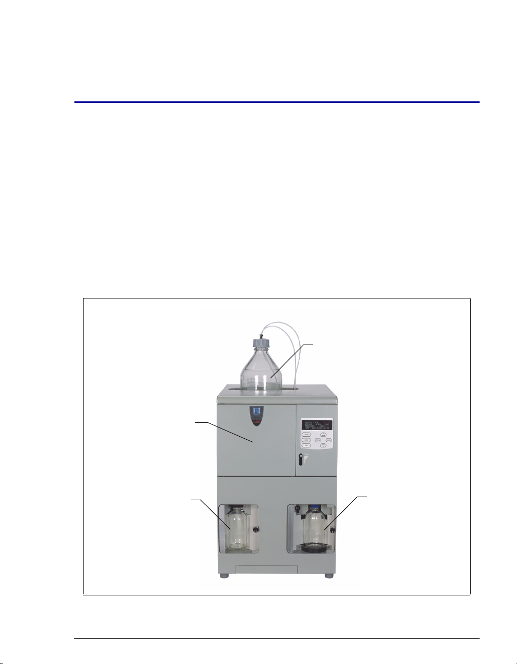
The ASE
®
150 Accelerated Solvent Extractor is a system for extracting either
organic or inorganic compounds from a variety of solid or semisolid samples at a
variety of pH values. The ASE 150 can be used with organic solvent, aqueous
buffer, water, and small amounts of mineral acids. The ASE 150 accelerates the
traditional extraction process by using solvent at elevated temperatures and
pressures. Pressure is maintained in the sample cell to maintain the heated solvent
in a liquid state during the extraction. After heating, the extract is rinsed from the
sample cell into a collection vessel and is ready for analysis.
Solvent
Reservoir
Sample Cell
and Oven
Location
Waste
Figure 1-1. ASE 150 Accelerated Solvent Extractor
Doc. 065207-02 9/08 1
Collection Vessel
Page 10

ASE 150 Operator’s Manual
The ASE 150 is designed to minimize the amount of solvent used without
sacrificing the speed of extraction or ease of operation. Samples are extracted one
at a time, and the extraction process is typically completed in 15 to 25 minutes.
All functions are controlled from the ASE 150 front panel.
Built-in safety diagnostics monitor the system during operation. If a problem
occurs, the front panel displays an error message that identifies the problem. In
addition, the method currently running is aborted and basic system functions are
shut down until the situation is corrected.
1.2 About This Manual
1.2.1 Overview
The electronic version (i.e., PDF file) of the ASE 150 operator’s manual
contains numerous hypertext links that can take you to other locations
within the file. These links include:
• Table of contents entries
• Index entries
• Cross-references (underlined in blue) to sections, figures, tables, etc.
If you are not familiar with how to navigate PDF files, refer to the Help
system for Adob
Chapter 1
Introduction
Chapter 2
Description
Chapter 3
Operation and
Maintenance
Chapter 4
Troubleshooting
Chapter 5
Service
Appendix A
Specifications
2 Doc. 065207-02 9/08
e® Acrobat® or Adobe Reader® for assistance.
Introduces the ASE 150; explains the conventions used in
this manual, including safety-related information.
Describes ASE 150 operating features and the extraction
process.
Provides operating instructions and routine preventive
maintenance procedures.
Lists error messages and how to troubleshoot them; lists
operating problems and how to resolve them.
Provides step-by-step instructions for routine service and
parts replacement procedures that the user can perform.
Provides specifications and installation site requirements.
Page 11
1 • Introduction
Appendix B
Installation
Appendix C
User Interface
Appendix D
Reordering
Information
Appendix E
Theory of ASE
Describes how to install the ASE 150.
Illustrates and describes the display screens on the ASE
150 front panel.
Lists spare parts for the ASE 150.
Describes the theory behind performing extractions with
ASE.
1.2.2 Safety Messages and Notes
This manual contains warnings and precautionary statements that can
prevent personal injury and/or damage to the ASE 150 when properly
followed. Safety messages appear in bold type and are accompanied by
icons, as shown below.
Indicates an imminently hazardous situation which, if not avoided, will
result in death or serious injury.
Indicates a potentially hazardous situation which, if not avoided, may
result in death or serious injury.
Indicates a potentially hazardous situation which, if not avoided, may
result in minor or moderate injury. Also used to identify a situation or
practice that may seriously damage the instrument, but will not cause
injury.
Indicates that the function or process of the instrument may be
impaired. Operation does not constitute a hazard.
Messages d’avertissement en français
Signale une situation de danger immédiat qui, si elle n'est pas évitée,
entraînera des blessures graves à mortelles.
Doc. 065207-02 9/08 3
Page 12
ASE 150 Operator’s Manual
Signale une situation de danger potentiel qui, si elle n'est pas évitée,
pourrait entraîner des blessures graves à mortelles.
Signale une situation de danger potentiel qui, si elle n'est pas évitée,
pourrait entraîner des blessures mineures à modérées. Également
utilisé pour signaler une situation ou une pratique qui pourrait
gravement endommager l'instrument mais qui n'entraînera pas de
blessures.
Warnhinweise in Deutsch
Bedeutet unmittelbare Gefahr. Mißachtung kann zum Tod oder
schwerwiegenden Verletzungen führen.
Bedeutet eine mögliche Gefährdung. Mißachtung kann zum Tod oder
schwerwiegenden Verletzungen führen.
Bedeutet eine mögliche Gefährdung. Mißachtung kann zu kleineren
oder mittelschweren Verletzungen führen. Wird auch verwendet, wenn
eine Situation zu schweren Schäden am Gerät führen kann, jedoch
keine Verletzungsgefahr besteht.
Notes
Informational messages also appear throughout this manual. These are
labeled NOTE and are in bold type.
NOTE NOTES call attention to certain information. They alert
the user to an unexpected result of an action, suggest
how to optimize instrument performance, etc.
4 Doc. 065207-02 9/08
Page 13

1.3 Safety and Regulatory Information
The ASE 150 was manufactured by Dionex Corporation at the following location:
527 Lakeside Drive, Sunnyvale, CA 94088-3603 U.S.A. The ASE 150 is designed
for solvent extraction applications and should not be used for any other purpose.
Operation of an ASE 150 in a manner not specified by Dionex may result in
personal injury.
If you have a question regarding appropriate usage, contact Dionex before
proceeding. In the U.S., call 1-800-346-6390 and select the Technical Support
option. Outside the U.S., call the nearest Dionex office.
1.4 Safety Labels
The cTUVus Mark safety label and the CE Mark label on the ASE 150 indicate
that the ASE 150 is in compliance with the following standards.
EMC Susceptibility and Emissions
• EN 61326-1:2006
1 • Introduction
Safety
• CAN/CSA-C22.2 No. 61010-1:2004
• EN 61010-1:2001
• UL 3101-1/10.93
• UL 61010-1:2004
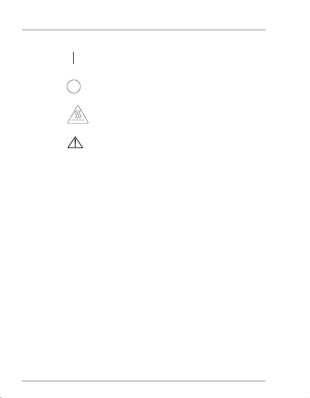
The symbols below appear on the ASE 150 or on ASE 150 labels.
Alternating current
Primary protective conductor terminal
Secondary protective conductor terminal
Doc. 065207-02 9/08 5
Page 14
ASE 150 Operator’s Manual
Power supply is on
Power supply is off
Hot surface
Indicates a potential hazard. Refer to the operator’s manual for
an explanation of the hazard and how to proceed.
6 Doc. 065207-02 9/08
Page 15
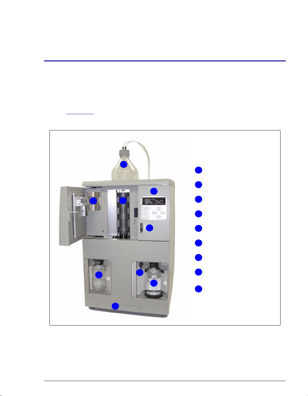
2.1 Operating Features
Figure 2-1 illustrates the main operating features of the ASE 150 Accelerated
Solvent Extractor.
2 • Description
1
4
2
6
3
5
7
8
9
Figure 2-1. ASE 150 Operating Features
Solvent Reservoir
1
2
Sample Cell
3
Oven
Control Panel
4
5
Door OPEN Lever
Waste Bottle
6
Needle UP/DOWN Switch
7
Collection Vessel
8
(250-mL bottle shown)
Drip Tray
9
Doc. 065207-02 9/08 7
Page 16

ASE 150 Operator’s Manual
Solvent Reservoir
A 2-liter solvent reservoir is installed in a recess on top of the ASE 150. The
recess contains a plastic liner that collects any solvent leaks or spills that may
occur and directs them through a drain tube to the rear panel. A drain hose
connects to the drain tube and is routed to a waste container.
Sample Cell
Before a sample is run or a rinse cycle is performed, a sample cell or rinse cell
must be installed in the cell holder on the inside of the cell door. To access the cell
holder, push down on the
Oven
The oven is located behind the cell door. This area also houses the AutoSeal™
tips, which seal the cell during a run.
Control Panel
The ASE 150 control panel includes a display screen and a membrane keypad,
which are used to control ASE 150 operation.
OPEN lever and then pull open the door.
Waste Bottle
The waste bottle is a 250-mL collection bottle that is sealed with a special built-in
cap assembly.
Needle Up/Down Switch
The UP/DOWN toggle switch controls the position of the source and vent needles.
When the needles are in the “down” position, they pierce the collection vessel
septum. The source needle allows the extract to flow from the sample cell into the
collection vessel. The vent needles allow displaced gases to escape to the waste
bottle and the system vent.
Drip Tray
A pull-out drip tray is installed below the oven to collect any liquid leaks that may
occur during a run or rinse cycle.
Collection Vessel
After each extraction, the collection vessel (either a 250-mL collection bottle or a
60-mL collection vial) contains solvent and the analytes extracted from the
sample.
8 Doc. 065207-02 9/08
Page 17
2 • Description
Safety Shields
The doors on the waste and collection vessel compartments are safety shields that
protect operators in the rare case of a bottle or vial breakage. The doors must be
closed for safe operation.
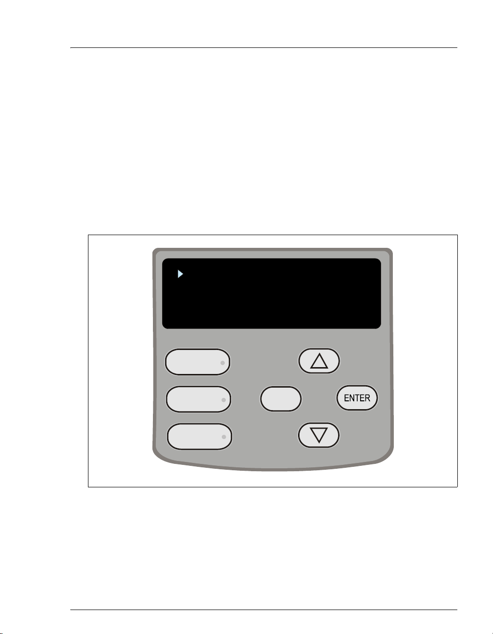
2.1.1 Control Panel
Use the control panel screen and buttons to control ASE 150 operation.
The screen displays status and operating information. You can edit any
field on the screen that contains a blinking cursor. A field without a
blinking cursor is for display only.
STATUS
SETUP
METHOD EDITOR
DIAGNOSTICS
START
RINSE
STOP
Figure 2-2. ASE 150 Control Panel
Doc. 065207-02 9/08 9
MENU
Page 18
ASE 150 Operator’s Manual
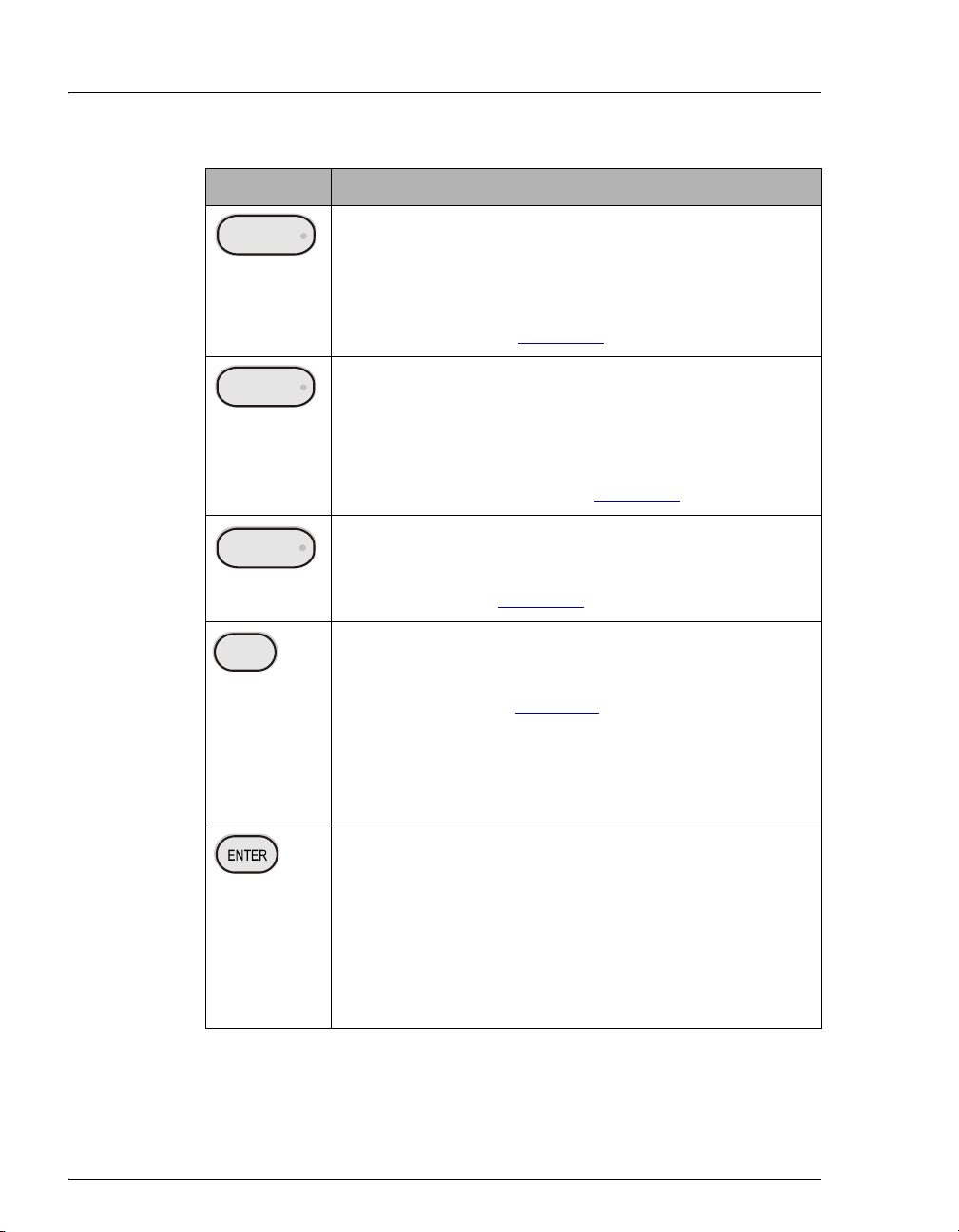
Button Function
START
RINSE
MENU
STOP
Starts the currently selected method. The LED starts flashing
when the oven is within 1 °C of the set point, indicating it is
okay to load the sample cell into the oven. During the method
run, the LED is lighted, but does not flash. When the method
finishes running (or is aborted), three beeps are emitted and
the LED turns off. See Section 2.4
for details about methods.
Starts a rinse cycle in which about 5 mL of solvent is pumped
through the system. During the rinse cycle, the LED is
lighted. When the rinse cycle is complete (or is aborted),
three beeps are emitted and the LED turns off.
Note: Always install a rinse cell and a collection vessel
before starting a rinse cycle. See Section 3.5
for instructions.
Interrupts the currently running method or rinse cycle and
displays the
ABORT screen. Pressing the button lights the
LED. The LED turns off when you select an option on the
ABORT screen. See Section 3.4 for details.
Exits the screen currently displayed and returns to the screen
one level up in the hierarchy. For example, if the
EDITOR
the
screen is displayed, pressing MENU returns you to
MENU screen. See Figure C-1 for an overview of the
METHOD
screens.
When the cursor is in an editable field, pressing
MENU
discards any change and reverts to the previously selected
parameter.
Selects the field the cursor is currently pointing to. On the
MENU or DIAGNOSTICS screen, this selects and displays a
different screen. On other screens, pressing
ENTER moves
the cursor from the left margin to the first field in that line
that can be edited; it also changes the normal cursor into the
blinking editing cursor.
When the cursor is in an editable field, pressing
ENTER saves
the parameter currently displayed in the field.
Table 2-1. ASE 150 Control Panel Button Functions
10 Doc. 065207-02 9/08
Page 19
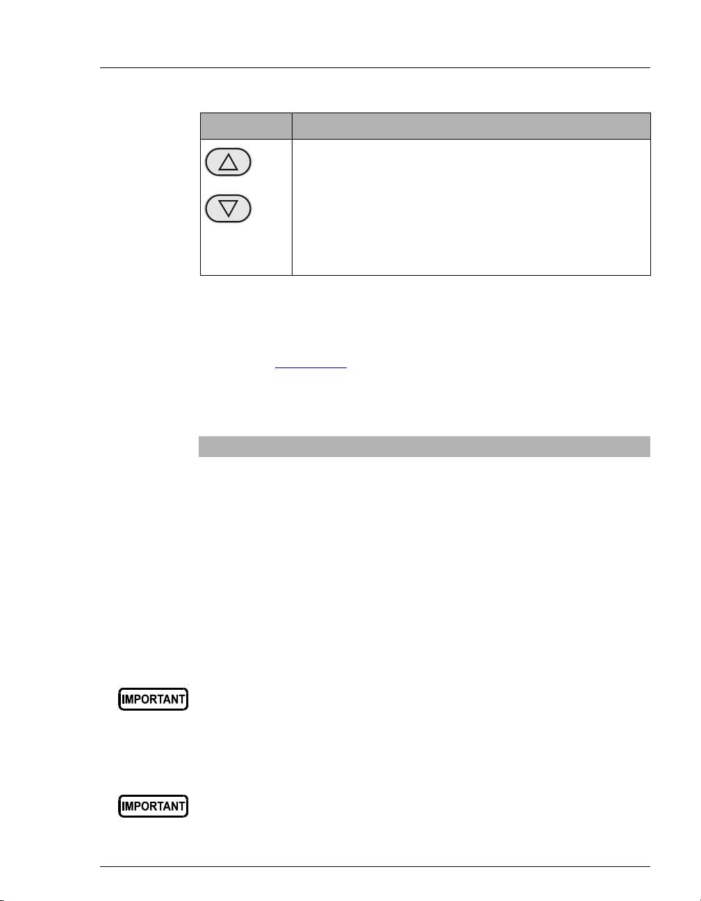
Button Function
Moves the cursor, in the direction of the arrow, to the next
selectable line on the display (if any).
When the cursor is in an editable field, pressing an arrow
button displays the next or previous parameter or numeric
value allowed for the field.
Note: Pressing and holding down an arrow button moves the
cursor continuously through the allowed settings.
Table 2-1. ASE 150 Control Panel Button Functions (Continued)
2.1.2 Sample Cells and Rinse Cells
NOTE Appendix D contains part numbers for cells, bottles,
vials, and other accessories.
Sample Cells
Cell Material Sizes Available (mL) Used For
Stainless steel 1, 5, 10, 22, 34, 66, and
100
Zirconium 66 and 100 Extraction of basic or acidic
2 • Description
Extractions with solvents
matrices, and extractions with
solvents
Sample cells consist of a cell body and two interchangeable caps, which
are screwed onto each end of the cell body. The cell body and end caps
are made of the same material. Inside each end cap is a frit in the same
material as the cell, as well as a PEEK™ seal. During a run, the cell end
caps are compressed by the oven to form a tight seal between the caps and
the cell body.
Always tighten the cell end caps by hand. Use of a wrench or other
tool can damage the cell, as well as the seals inside the cell end caps.
Each cell end cap contains an external O-ring. Teflon® O-rings
(P/N 049457, pkg. of 50) are standard. Use Viton® O-rings (P/N 056325,
pkg. of 50) for dioxins and other high temperature applications.
If Viton external O-rings are installed on the cell end caps, do not use
acetone or other ketones.
Doc. 065207-02 9/08 11
Page 20

ASE 150 Operator’s Manual
Rinse Cells
Rinse cells are similar in appearance to sample cells, but are blue in color.
During a rinse cycle, solvent passes directly through the rinse cell and
into the collection vessel. For more information about rinse cycles, see
Section 3.5
The rinse cell size must be matched to the size of the sample cell, as
indicated in the table below.
Use this rinse cell: With this sample cell:
Short (P/N 060174) 1 mL, 5 mL, 10 mL, 22 mL, 34 mL
Medium (P/N 060175) 66 mL
Long (P/N 060176) 100 mL
Ordering Sample Cells in Other Sizes
To perform a run with a cell in a different size than the size originally
ordered, order the cells from Dionex. You will also need to order the
Startup Kit appropriate for the new cell size. For cell and Startup Kit part
numbers, see Appendix D
.
.
Note that installation of a different sample cell size will require a few
additional changes:
• Reposition the cell holder to accommodate the new sample cell size,
if required. For instructions, refer to Section B.2.8
.
• Before beginning a run, specify the new cell size on the SETUP screen
(see Section C.1.3
12 Doc. 065207-02 9/08
).
Page 21
2.1.3 Collection Vessels
The following collection vessels are available:
Collection Vessel Part Number Quantity
60-mL clear vials 048784 Pkg. of 72
60-mL amber vials 048781 Pkg. of 72
60-mL clear graduated vial, Class A 068226 1
60-mL clear graduated vial, Class B 068248 1
250-mL clear bottles 056284 Pkg. of 12
250-mL clear graduated bottle, Class A 068225 1
250-mL clear graduated bottle, Class B 068249 1
Before each run, carefully inspect all collection vessels for chips,
scratches, or cracks. If a collection vessel shows any sign of damage,
do not use it.
Use each nongraduated collection vessel once only. Graduated
collection vessels may be used multiple times, provided they are
undamaged.
La présence de fêlure ou d’égratignures sur les flacons de collecte
doit être vérifiée avant chaque extraction. N’utilisez jamais un flacon
endommagé.
Les flacons non gradués sont à usage unique. Les flacons gradués
peuvent être réutilisés tant qu’ils sont intacts.
Untersuchen Sie vor jedem Lauf alle Sammelgefäße auf
Abplatzungen, Kratzer oder Risse. Wenn ein Sammelgefäß eine
Beschädigung aufweist, sollten Sie es nicht mehr verwenden.
Graduierte Sammelgefäße können mehrfach verwendet werden,
vorausgesetzt sie weisen keine Beschädigung auf.
2 • Description
Use each collection vessel cap and septum once only. This prevents
solvent leaks caused by piercing the septum in the cap multiple times.
An adapter (P/N 066392) is required to install a 60
-mL vial in the
collection vessel area. The adapter is included in the Startup Kits for
1
-mL, 5-mL, 10-mL, 22-mL, and 34-mL sample cells.
The collection vessel caps (used with all bottles and vials) contain a
solvent-resistant septum. During a run, the needle mechanism is lowered
so that the needles pierce the septum, creating a liquid flow path from the
Doc. 065207-02 9/08 13
Page 22
ASE 150 Operator’s Manual
sample cell to the collection vessel. After a run, the collection vessel
contains solvent and the analytes extracted from the sample.
2.1.4 Solvent Reservoir
The ASE 150 Ship Kit (P/N 066399) includes a 2-liter glass bottle with
shatterproof plastic coating (P/N 045901) and a bottle cap assembly
(P/N 068077) with tubing and fittings for the inlet and outlet connections.
For instructions on how to install the solvent reservoir, see Section 3.1.2
Use only Dionex solvent reservoirs. These are glass bottles with a
shatterproof plastic coating. To prevent operator injury, make sure the
pressure applied to the bottles does not exceed 0.07 MPa (10 psi).
Utilisez uniquement des réservoirs à solvant Dionex. Ce sont des
réservoirs en verre à revêtement incassable en plastique. Veillez à ce
que la pression exercée sur ces réservoirs ne dépasse pas 0,07 MPa.
Verwenden Sie ausschließlich die Lösemittelbehälter von Dionex.
Dabei handelt es sich um Glasbehälter mit einer splittersicheren
Plastikbeschichtung. Vergewissern Sie sich, daß der Druck, der auf
die Behälter ausgeübt wird, 0,07 MPa nicht übersteigt.
.
Never fill the solvent reservoir or disconnect the tubing connections
to the solvent and gas connectors during a run or rinse cycle. At these
times, the solvent reservoir is pressurized. If you remove the bottle
cap, the ASE 150 may not operate to specification.
2.1.5 Waste Bottle
A 250-mL collection bottle (without the cap) is used to collect system
waste. Three vent lines, one from the pressure relief valve and two from
the needle mechanism, are connected to the built-in waste bottle cap. The
waste bottle collects the small amounts of condensed solvent vented
through these lines.
A vent outlet line is also connected to the waste bottle cap; gas is vented
out this line to the rear panel. The ASE 150 Ship Kit (P/N 066399)
provides vent tubing (P/N 053514) that you can connect to the vent outlet
on the rear panel (see Figure 2-3
NOTE Check the waste bottle daily and empty whenever
necessary.
14 Doc. 065207-02 9/08
) and then route to a vent hood.
Page 23
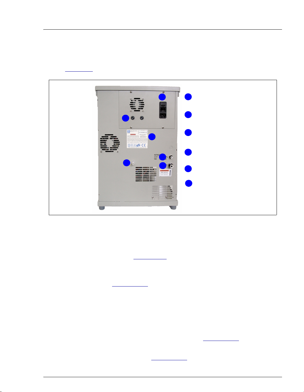
2.2 Rear Panel
Figure 2-3 illustrates the rear panel of the ASE 150.
2 • Description
Power
1
2
3
6
4
5
1
Oven Voltage
2
Switches
Model Data
3
Label
Nitrogen Gas
4
Inlet
5
Vent Outl et
Drain
6
Figure 2-3. ASE 150 Rear Panel
• The POWER switch provides on/off control of the main power for the system.
The power receptacle also includes the fuse holder. For instructions on how to
replace the fuses, see Section 5.10
.
• The oven voltage switches must be set to match the voltage from the power
source at the ASE 150 installation site. For instructions on how to set the
switches, see Section B.2.3
.
• The model data label lists fuse and power information, as well as the ASE 150
serial number. You will be asked to provide the serial number when ordering
replacement parts for the system.
• The NITROGEN connector is connected to a nitrogen supply regulated to
between 0.97 and 1.38 MPa (140 and 200 psi); 1.03 MPa (150 psi) is
recommended. For installation instructions, see Section B.2.1
.
• The VENT connector provides a connection for the vent outlet line. For
installation instructions, see Section B.2.1
Doc. 065207-02 9/08 15
.
Page 24

ASE 150 Operator’s Manual
• The drain directs solvent spills from the bottle area on top of the ASE 150 to
the rear panel. A drain hose connects to the fitting. For installation
instructions, see Section B.2.2
.
2.3 ASE 150 Extraction Process
Preparing to Run an Extraction
The following steps are required before the ASE 150 can perform an extraction.
Refer to Chapter 3
• Fill the solvent reservoir.
• Prepare the sample and load it into the sample cell.
• Install the waste bottle and collection vessel.
• Select or create a method.
• Press the START button.
• Verify that the STATUS on the STATUS screen is OVEN READY (see Figure 2-5)
and the LED on the
for detailed instructions for each step.
START button is flashing.
• Install the sample cell in the cell holder and close the cell door.
• Press the START button.
16 Doc. 065207-02 9/08
Page 25
2 • Description
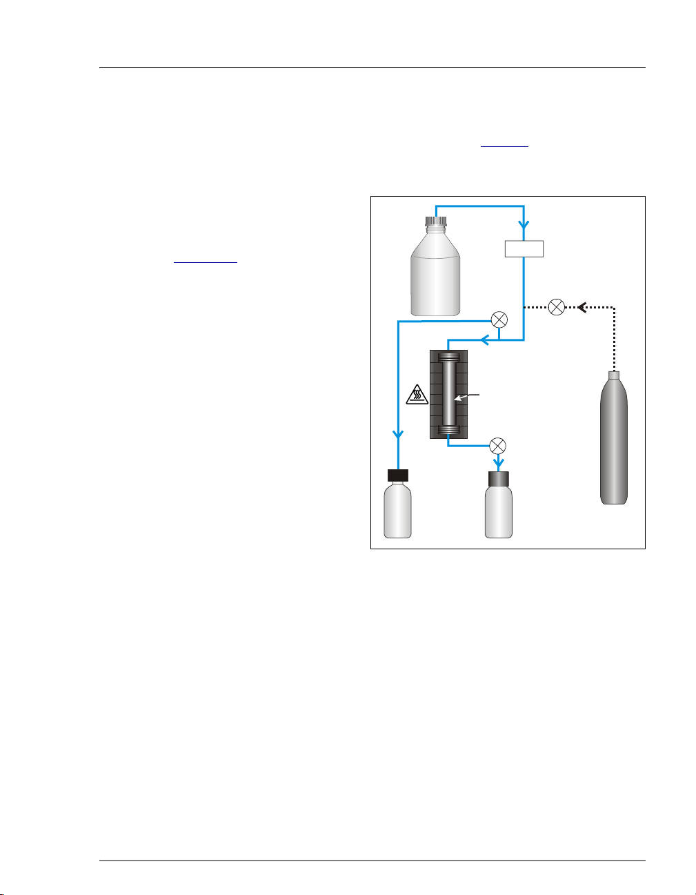
Performing the Extraction
After you complete the preparation steps described on page 16 and press START
the second time, the ASE 150 performs the extraction. The extraction process
consists of six main steps.
1. Fill the cell with solvent—the
pump is turned on and the
static valve is closed (see
Figure 2-4
). Solvent is pumped
into the sample cell until the
cell pressure reaches
10.35 MPa (1500 psi).
Thereafter, the static valve
opens occasionally to maintain
the pressure at 10.35 MPa
(1500 psi).
2. Heat the cell (equilibration)—
the temperature in the cell is
heated to the set point
specified in the method.
Solvent
Bottle
Oven
Pump
Pressure
Relief
Valve
Purge Valve
Sample
Cell
Static Valve
3. Static extraction—the cell
remains filled with the solvent
at the temperature set point.
Waste
Bottle
Figure 2-4. Extraction Process Schematic
Collection
Vessel
Nitrogen
4. Rinse with fresh solvent—the static valve opens and the extract flows into the
collection vessel. Fresh solvent is pumped through the cell.
5. Purge solvent from the system—the purge valve opens and gas purges the
remaining solvent from the cell into the collection vessel.
6. Relieve pressure—the pressure relief valve opens and residual pressure is
released from the cell.
NOTE Static extraction and rinsing can be repeated multiple
times.
Doc. 065207-02 9/08 17
Page 26

ASE 150 Operator’s Manual
Monitoring the Progress of a Run
To monitor the progress of a run, press MENU, move the cursor to STATUS (if
necessary), and press
ENTER. The STATUS screen appears (see Figure 2-5).
STATUS STATIC
METHOD PCB
PRESSURE
TEMP 100C
Figure 2-5. Status Screen Example
The
STATUS screen operating parameters are updated in real time.
• STATUS—the current system status. During a run, the status field displays the
following status states (in the order given): Oven Wait, Oven Ready, Load,
Preheat (optional), Fill, Heat, Static, Rinse, Purge, Relief, Unload, and Idle.
• METHOD—the name or number of the current method.
• VOL—the approximate volume of solvent (in mL) delivered by the pump
since the method started running.
VOL
1565PSI
TIME
75mL
2:25
• PRESSURE—the current sample cell pressure reading.
• TEMP—the temperature specified in the method.
• TIME—the elapsed time since the method started running.
18 Doc. 065207-02 9/08
Page 27

2.4 Method Control
A method determines how the ASE 150 performs the sample extraction. Methods
are defined on the
METHOD EDITOR screen (see Figure 2-6).
2 • Description
METHOD
TEMPERATURE
STATIC TIME
RINSE VOLUME
Figure 2-6. Method Editor Screen (Initial View)
The following method parameters define the method. See Section C.1.4
detailed descriptions of the method parameters.
1
100C
5MIN
60%
for
• TEMPERATURE—the temperature at which to heat the cell.
• STATIC TIME—the number of minutes to maintain the cell contents (sample
and solvent) at the temperature set point.
• RINSE VOLUME—the amount of solvent to rinse through the sample cell after
the static extraction.
• PURGE TIME—the amount of time the cell is purged with nitrogen.
• STATIC CYCLE—the number of times the static extraction and rinse cycles are
performed.
• CELL TYPE—the type of cell to use (stainless steel or zirconium).
Two types of methods are available:
• Preprogrammed methods are application-specific methods created by Dionex.
These methods cannot be changed or deleted by the user. For a list of the
parameters for each preprogrammed method, see Section 2.5
.
• Custom methods are user-programmable methods. All custom methods
initially contain the default method parameters. You can modify these
methods as required. For instructions on how to edit a custom method, see
Section 3.6
Doc. 065207-02 9/08 19
.
Page 28

ASE 150 Operator’s Manual
2.5 Preprogrammed Methods
To help you quickly produce results with the ASE 150, Dionex provides nine
preprogrammed methods. These methods are designated by three-letter
abbreviations (see the table below).
Preprogrammed Method Method Name
Semivolatiles BNA
Total Fat (crude) FAT
Chlorinated Herbicides HRB
Organochlorine Pesticides OCP
Organophosphorous Pesticides OPP
Polychlorinated Biphenyls PCB
Dioxins and Furans PDF
Polymer Additives PPE
Total Petroleum Hydrocarbons TPH
The remainder of this section lists the recommended solvent and the operating
conditions for each preprogrammed method. You cannot edit or delete a
preprogrammed method.
BNA (Semivolatiles) Method Parameters
Solvent MeCl2/Acetone (1:1, v/v)
Temperature 100 °C
Static Time 5 min
Rinse Volume 60%
Purge Time 100 sec
Static Cycle 1
Cell Type Stainless steel
20 Doc. 065207-02 9/08
Page 29

2 • Description
FAT (Total Fat) Method Parameters
Solvent Hexane/Acetone (4:1)
Temperature 125 °C
Static Time 5 min
Rinse Volume 100%
Purge Time 60 sec
Static Cycle 3
Cell Type Stainless steel
HRB (Chlorinated Herbicides) Method Parameters
Solvent MeCl2/Acetone (1:1) with 1%
H
3PO4
Temperature 100 °C
Static Time 5 min
Rinse Volume 60%
Purge Time 100 sec
Static Cycle 1
Cell Type Stainless steel
OCP (Organochlorine Pesticides) Method Parameters
Solvent Hexane/Acetone (1:1, v/v)
Temperature 100 °C
Static Time 5 min
Rinse Volume 60%
Purge Time 100 sec
Static Cycle 1
Cell Type Stainless steel
Doc. 065207-02 9/08 21
Page 30

ASE 150 Operator’s Manual
OPP (Organophosphorous Pesticides) Method Parameters
Solvent MeCl2/Acetone (1:1, v/v)
Temperature 100 °C
Static Time 5 min
Rinse Volume 60%
Purge Time 100 sec
Static Cycle 1
Cell Type Stainless steel
PCB (Polychlorinated Biphenyls) Method Parameters
Solvent Hexane
Temperature 100 °C
Static Time 5 min
Rinse Volume 60%
Purge Time 100 sec
Static Cycle 1
Cell Type Stainless steel
PDF (Dioxins and Furans) Method Parameters
Solvent Toluene
Temperature 200 °C
Static Time 5 min
Rinse Volume 60%
Purge Time 100 sec
Static Cycle 1
Cell Type Stainless steel
22 Doc. 065207-02 9/08
Page 31

2 • Description
PPE (Polymer Additives) Method Parameters
Solvent 2.5% Cyclohexane in Isopropyl
Alcohol
Temperature 140 °C
Static Time 3 min
Rinse Volume 100%
Purge Time 60 sec
Static Cycle 3
Cell Type Stainless steel
TPH (Total Petroleum Hydrocarbons) Method Parameters
Solvent MeCl2/Acetone (1:1, v/v)
Temperature 175 °C
Static Time 5 min
Rinse Volume 60%
Purge Time 100 sec
Static Cycle 1
Cell Type Stainless steel
Doc. 065207-02 9/08 23
Page 32

ASE 150 Operator’s Manual
24 Doc. 065207-02 9/08
Page 33

3 • Operation and Maintenance
3.1 Preparing to Run
3.1.1 Selecting and Preparing Solvent
Precautions
Do not use solvents with an autoignition point below 200 °C. The table
below lists some solvents that should not be used with the ASE 150. If
you have a question about solvent suitability, contact Dionex.
Do Not Use These Solvents Autoignition Point
Carbon disulfide: CS
Diethylether: (C
1,4-dioxane: C
N'utilisez pas de solvants ayant un point éclair inférieur à 200 °C. Le
tableau ci-dessous liste quelques solvants qui ne doivent pas être
utilisés avec l'ASE 150. Contactez Dionex si vous avez un doute
concernant l’usage d’un solvant absent de la liste.
2
O 180 °C
2H5)2
4H8O2
100 °C
180 °C
Solvants à ne pas utiliser Point d'auto-inflammation
Disulfure de carbone: CS
Éther diéthylique: (C
1,4-dioxane: C
Verwenden Sie keine Lösungsmittel, deren Selbstentzündungstemperatur unter 200°C liegt. Die untenstehende Tabelle zeigt einige
Lösungsmittel, die Sie nicht mit dem ASE 150 verwenden sollten. Bei
Fragen zur Eignung von Lösungsmitteln wenden Sie sich bitte an
Dionex.
Nicht zu verwendende
Lösungsmittel
4H8O2
Kohlendisulfid: CS
Diethyläther: (C
1,4-dioxan: C
Doc. 065207-02 9/08 25
2H5)2
4H8O2
2
2H5)2
2
O180 °C
100 °C
O 180 °C
180 °C
Selbstentzündungstemperatur
100 °C
180 °C
Page 34

ASE 150 Operator’s Manual
Guidelines for Selecting and Preparing Solvents
• When developing a new method, select a solvent or solvent mixture
that has a high solubility for the analytes of interest, but not for the
sample matrix. If you have been using another method (Soxhlet, for
example), use the same solvent with the ASE 150 that you used with
the other method.
• Before running a preprogrammed method, refer to Section 2.5 for the
recommended solvent.
• Use HPLC-grade or pesticide-grade solvents.
• Use organic or aqueous solvents.
• Use single-component or multiple-component solvents.
• Solvents do not generally need to be degassed. Degas solvents only if
the analyte of interest oxidizes easily.
• If Viton external O-rings are installed on the cell end caps, do not use
acetone and other ketones.
• Although the zirconium components in the ASE 150 flow path are
more resistant to acids and bases at elevated temperatures than other
metallic materials, follow these guidelines to prevent degradation and
ensure optimum performance:
a. As a general rule, strong mineral acids such as hydrochloric acid
should not be used (at any concentration) as extraction solvents.
This is because there are components in the flow path of the
system (for example, the pump head) that are constructed of
stainless steel and will corrode when used with strong acids.
Sulfuric acid or nitric acid can be pumped as a solvent at
concentrations less than 0.1% by volume. For additional details
about acids that can be pumped as solvents, see Table 3-1
Using corrosive acids or bases can damage stainless steel cells and
will void the product warranty.
b. Weak bases such as ammonia can be used at small percentages
(<5% by volume). Strong bases such as sodium hydroxide or
potassium hydroxide can be pumped as extraction solvents at
concentrations less than 0.1% by volume. For additional details
about bases that can be pumped as solvents, see Table 3- 1
26 Doc. 065207-02 9/08
.
.
Page 35

3 • Operation and Maintenance
c. Weak acids such as phosphoric or acetic acid can be used as
extraction solvents in small percentages (<5% by volume). Weak
bases such as ammonia can be used at small percentages (<5% by
volume).
d. Noncorrosive additives such as buffers (acetate, phosphate, etc.)
can be used as extraction solvents at moderate percentages.
e. In some cases, nitric or hydrochloric acid can be added directly to
the sample before it is placed into a zirconium cell (not a stainless
steel cell). For example, 1 to 2 mL of 5% to 10% HCl can be
added directly to a soil sample before it is loaded into a zirconium
cell for extraction.
f. Table 3- 1
lists the allowable concentrations for several acids and
bases. If a sample needs to be treated with acids stronger than the
concentrations here, pretreat the sample with the concentrated
acid before loading it into a zirconium cell (not a stainless steel
cell). For more details about sample preparation, see
Section 3.1.3
Acid or Base Concentration
HCl 8 M No No Yes
HCl 10% No Yes Yes
HCl 0.1 M No Yes Yes
NaOH 8 M No No N/A
NaOH 10% No Yes N/A
NaOH 0.1 M Yes Yes N/A
H
8 M No No Yes
2SO4
Okay to pump from
solvent reservoir?
(Okay to use SST
or Zr cells)
.
Add to sample and
transfer to Zr cell?
(Do not use SST
cells)
Add to sample
matrix with ASE
Prep CR and transfer to Zr cell? (Do
not use SST cells)
10% No Yes Yes
H
2SO4
5% solution Yes Yes Yes
H
2SO4
Table 3-1. Guidelines for Use of Acids and Bases with the ASE 150
Doc. 065207-02 9/08 27
Page 36

ASE 150 Operator’s Manual
Acid or Base Concentration
Okay to pump from
solvent reservoir?
(Okay to use SST
or Zr cells)
Add to sample and
transfer to Zr cell?
(Do not use SST
cells)
Add to sample
matrix with ASE
Prep CR and transfer to Zr cell? (Do
not use SST cells)
H2SO4 0.1 M Yes Yes Yes
KOH 8 M No No N/A
KOH 10% No Yes N/A
KOH 0.1 M Yes Yes N/A
HNO
8 M No No Yes
3
10% Yes Yes Yes
HNO
3
0.1 M Yes Yes Yes
HNO
3
OH 8 M No No N/A
NH
4
OH < 5% Yes Yes N/A
NH
4
OH 0.1 M Yes Yes N/A
NH
4
Trifluoroacetic acid
Ye s Ye s Ye s
< 5%
Acetic acid < 5% Yes Yes Yes
Phosphoric acid
Ye s Ye s Ye s
<5%
Table 3-1. Guidelines for Use of Acids and Bases with the ASE 150 (Continued)
If acids, bases, salts, or buffers are used as extraction solvents, rinse
the system with 100% polar organic solvent (for example, acetone or
methanol) or distilled water before turning off the power.
28 Doc. 065207-02 9/08
Page 37

3 • Operation and Maintenance
3.1.2 Filling the Solvent Reservoir
Use only Dionex solvent reservoirs. These are glass bottles with a
plastic, shatterproof coating. Make sure the pressure applied to the
bottles does not exceed 0.07 MPa (10 psi).
Utilisez uniquement des réservoirs à solvant Dionex. Ce sont des
réservoirs en verre à revêtement incassable en plastique. Veillez à ce
que la pression exercée sur ces réservoirs ne dépasse pas 0,07 MPa.
Verwenden Sie ausschließlich die Lösemittelbehälter von Dionex.
Dabei handelt es sich um Glasbehälter mit einer splittersicheren
Plastikbeschichtung. Vergewissern Sie sich, daß der Druck, der auf
die Behälter ausgeübt wird, 0,07 MPa nicht übersteigt.
Never fill the solvent reservoir or disconnect the tubing connections
to the solvent and gas connectors (see Figure 3-1
rinse cycle. At these times, the solvent reservoir is pressurized. If you
remove the bottle cap when the solvent reservoir is pressurized, the
ASE 150 may not operate to specification.
1. If you plan to run a preprogrammed method, refer to Section 2.5 for
the recommended solvent. If you plan to run a custom method, review
the solvent selection guidelines in Section 3.1.1
) during a run or
.
2. Fill the solvent reservoir with prepared solvent to the level indicated
in Figure 3-1
NOTE The solvent level in the reservoir must remain
.
below the gas line. This prevents solvent from
coming into contact with the pneumatic valves.
3. Place the bottle in the recess on top of the system.
4. Insert the solvent and gas lines extending from the underside of the
bottle cap assembly into the bottle (see Figure 3-1
). Make sure the
end-line filter on the solvent line rests on the bottom of the bottle.
5. Hand-tighten the lock ring cap securely over the stopper.
6. If they are not already connected, screw the solvent line fitting into
the solvent connector on the ASE 150 and then push the gas line
fitting into the gas connector.
Doc. 065207-02 9/08 29
Page 38

ASE 150 Operator’s Manual
NOTE Always connect the solvent line to the solvent
connector first, and then the gas line to the gas
connector. If you need to disconnect the lines,
reverse the order. It is not necessary to
disconnect the solvent and gas lines before
refilling the bottle.
End-Line Filter
Figure 3-1. Solvent Reservoir Connections
30 Doc. 065207-02 9/08
Page 39

3.1.3 Preparing the Sample
If you have successfully followed a particular sample pretreatment
procedure for another extraction method, continue using this procedure
with the ASE 150. If you have never run an extraction—or if you are
preparing a new sample—follow the guidelines here. This section
discusses two sample pretreatment procedures:
• Samples that are dry, wet, or liquid should be mixed with a drying or
dispersing agent before being loaded into the cells.
• Samples with large particle sizes should be ground before being
loaded into the cells.
NOTE: Most problems with the ASE (accelerated solvent extraction)
process are caused by errors made during sample preparation. To obtain
high quality analytical results, pay careful attention to the sample
preparation phase of the method. For more details, see Appendix E
Guidelines for Selecting a Drying or Dispersing Agent
• Although sodium sulfate is readily available, it should not be used in
ASE 150 cells. The use of sodium sulfate with very wet samples
(30% moisture) will result in clogging of system components (such as
the solvent line or needles) with recrystallized sodium sulfate. This
occurs particularly if a mixed solvent with a polar component such as
methanol or acetone is used. In these cases, use pelletized
diatomaceous earth (DE) (P/N 062819) as a drying agent and mix it
with the sample before loading into the sample cell (see the sample
preparation guidelines on page 32
a drying agent in the cell in place of sodium sulfate for all levels of
moisture.)
3 • Operation and Maintenance
.
). (Alternatively, DE can be used as
• For very wet samples, regardless of which drying agent is used, you
may add sodium sulfate to the collection vessels after collection and
then pass the extracts through either a drying column or drying
cartridge to dry the extract completely. At the temperatures used
during ASE 150 extractions, more water is co-extracted than with
other extraction procedures. To ensure good analyte recovery,
thoroughly rinse the sodium sulfate out of the collection vessel and
the cleanup column.
Doc. 065207-02 9/08 31
Page 40

ASE 150 Operator’s Manual
• If a sample needs to be treated with acids stronger than the
concentrations listed in Table 3- 1
concentrated acid before loading it into the cell. After the
pretreatment, mix the sample with ASE Prep CR Resin (P/N 080024)
to partially neutralize the acid to approximately 0.1 M. The sample
may need to be mixed with pelletized diatomaceous earth (DE)
(P/N 062819) to absorb water, depending on how much acid was used
to pretreat the sample.
For example, if a food sample is treated with 10 mL of 8 M HCl, mix
the liquid hydrolysate with 30 to 40 g of ASE Prep CR and 15 g of
DE. When the sample is thoroughly mixed, add it to the zirconium
cell. (Do not use a stainless steel cell.) Use this ratio of acid to ASE
Prep CR whenever using strong acids for pretreatment of samples.
If you have any questions about compatibility of an acid or base,
please contact Dionex.
Guidelines for Sample Preparation with a Drying or Dispersing
Agent
, pretreat the sample with the
The following mixtures are recommendations only; adjust the proportions
as required.
• If the sample appears dry, use this mixture:
4 grams sample to 1 gram DE
Mix the sample and the DE thoroughly in a small bottle, beaker, or
mortar.
• If the sample appears wet, use this mixture:
4 grams sample to 2 grams DE
Mix the sample and the DE thoroughly in a small bottle, beaker, or
mortar.
• If the sample is pure liquid, use 5 grams sample to 3 grams DE.
Fill the cell with DE and then add the sample.
NOTE Certain pure liquid samples may be mixed with
drying or dispersing agents other than DE. For
a current list of approved materials, contact
Dionex.
32 Doc. 065207-02 9/08
Page 41

3 • Operation and Maintenance
Guidelines for Grinding
• For an efficient extraction to occur, the solvent must make contact
with the target analytes. The more surface area that can be exposed in
a sample, the faster extraction will occur. Therefore, samples with
large particle sizes should be ground prior to extraction. Often a large,
representative sample can be ground, and then weighed portions of
the ground sample can be used for extraction.
• Soil and sediment samples usually do not need to be ground, but it
may be necessary to remove stones or sticks from the samples prior to
extraction.
• Polymer samples must be in a ground state for an efficient extraction
of additive compounds. Materials such as polymers and rubbers are
best ground at reduced temperatures; for example, liquid nitrogen.
• Animal or plant tissue samples can be homogenized using any
procedure such as a blender or tissue homogenizer.
Sample Preparation by Grinding
Grind the sample with any of the following tools: a conventional mortar
and pestle, an electric grinder, or an electric mill. For the most efficient
extraction, grind until particles are smaller than 1 mm.
Doc. 065207-02 9/08 33
Page 42

ASE 150 Operator’s Manual
3.1.4 Installing the Cell Filter
A disposable filter must be installed in the bottom end cap of the sample
cell before sample is loaded. The filter prevents blockage of the frit in the
bottom cap. For installation instructions, see page 34
to the information here to determine the appropriate filter material and
size.
Cell filters are available in two materials:
• Use cellulose filters for most extraction methods that use organic
solvents.
• Use glass-fiber filters for aqueous extractions, where cellulose may
provide inadequate filtration or may interfere with the analytical
technique.
Cell filters are available in two sizes:
• Use 27-mm filters for 1-mL, 5-mL, 10-mL, or 22-mL cells.
• Use 30-mm filters for 34-mL, 66-mL, or 100-mL cells.
Each ASE 150 Startup Kit includes a package of 100 cellulose filters, in
the size appropriate for the sample cell size to be used. For information
about reordering filters or ordering filters in a different material or size,
refer to Appendix D
and page 35. Refer
.
To install a 27-mm filter in a 1-, 5-, 10-, or 22-mL cell:
1. Unscrew the bottom cap from
the cell body.
Groove
To identify the cell top and
bottom, designate the end of the
cell with the groove around the
body and the Dionex logo, serial
Logo, Serial
Number,
and Size
number, and cell size as the cell
top (see Figure 3-2
34 Doc. 065207-02 9/08
).
Figure 3-2. Sample Cell Top (Smaller Cells)
Page 43

3 • Operation and Maintenance
2. Place a 27-mm filter in the
center of the cell bottom cap
(see Figure 3-3
).
PEEK
Bottom Cap of a
1-, 5-, 10-, or 22-mL Cell
Seal
3. To prevent leaks, check that no
part of the filter overlaps onto
the PEEK seal.
Figure 3-3. Installing a 27-mm Cell Filter
27-mm Filter
4. Carefully place the cell body over the bottom cap, screw the body
onto the cap, and hand-tighten.
Always tighten the cell end caps by hand. Use of a wrench or other
tool can damage the cell, as well as the seals inside the cell end caps.
To install a 30-mm filter in a 34-, 66-, or 100-mL cell:
1. Unscrew the top cap from the cell
body and verify that a cap is
installed on the bottom of the cell.
Groove
To identify the cell top and bottom,
designate the end of the cell with
the groove around the body and the
Logo and
Serial
Number
Dionex logo and serial number as
the cell top (see Figure 3-4
Always tighten the cell end caps by hand. Use of a wrench or other
tool can damage the cell, as well as the seals inside the cell end caps.
Do not place the 30-mm filter in the bottom cap before installing the
cap; this creates an improper seal and allows leaks.
).
Figure 3-4. Sample Cell Top (Larger Cells)
2. Follow the steps in Figure 3-5 to install the 30-mm filter.
Doc. 065207-02 9/08 35
Page 44

ASE 150 Operator’s Manual
Insert a 30-mm
filter into the
cell at a slight
angle.
Position the filter
insertion tool
(P/N 056929)
over the filter.
Slowly push the
insertion tool
straight into the
cell.
Push down until
the filter is in full
contact with the
end cap.
Figure 3-5. Installing a 30-mm Cell Filter in a 34-, 66-, or 100-mL Cell
NOTE The procedure for installing 30-mm filters in
stainless steel and zirconium cells is the same.
The photos in Figure 3-5
show a zirconium cell.
36 Doc. 065207-02 9/08
Page 45

3.1.5 Filling the Cell
Precautions:
• When filling the cell with sample, keep the threads on the cell body
and end cap as clean as possible to prevent thread fouling and extend
the life of the cell.
• Also make sure that the ends of the cell body and the seals in the end
caps are clean; if debris remains here, it will damage the cell body
and/or allow leaks during the run.
To fill a cell:
1. Use the funnel provided in the ASE 150 Startup Kit to carefully load
the sample into the top of the sample cell. To accommodate different
sample cell sizes, three funnels (with different inner diameters) are
available (see Figure 3-6
3 • Operation and Maintenance
).
Funnel for 1-mL cells
(P/N 068076
)
Funnel for 5-, 10-, and
22-mL cells (P/N 068075
Figure 3-6. Sample Funnels
)
Funnel for 34-, 66-, and
100-mL cells (P/N 056699
)
2. (Optional) To reduce the amount of solvent used during the run, fill
any void volume in the cell with an inert material such as Ottawa sand
(Fisher S23-2).
3. Using a soft brush or cloth, wipe all debris off the threads of the top
cell end cap.
4. Screw the top cap onto the cell body. Hand-tighten the cap.
Always tighten the cell end caps by hand. Use of a wrench or other
tool can damage the cell, as well as the seals inside the cell end caps.
Doc. 065207-02 9/08 37
Page 46

ASE 150 Operator’s Manual
s
5. Check the ends of each cell end cap
to verify that the O-rings are in
place and are in good condition
(see Figure 3-7
• If an O-ring is dislodged, press
it into place, using the O-ring
insertion tool (P/N 049660),
provided in the ASE 150 Ship
Kit (P/N 066399).
• If an O-ring is missing, place a
new O-ring over the opening in
the end of the cell end cap.
Press the O-ring into place,
using the O-ring insertion tool
(see Figure 3-8
information about ordering Orings, refer to Appendix D
).
). For
Verify that O-ring
are installed and
in good condition
Figure 3-7. Inspecting Cell O-Rings
O-Ring Insertion Tool
(P/N 049660)
Place O-ring in opening
and press into place
.
with insertion tool.
• If any O-ring has a hole size of
less than 0.5 mm, replace it. If
a white Teflon O-ring is
discolored, replace it (see the
following instructions).
Figure 3-8. Installing a Cell End Cap O-Ring
To replace a cell end cap O-ring:
Be careful not to scratch the interior of the cell end cap when
installing or removing the cell O-ring. Scratches on the sealing
surface will prevent the O-ring from sealing properly and may result in
leaks during operation.
1. Locate the small flathead screwdriver (P/N 046985) in the ASE 150
Ship Kit (P/N 066399).
2. Insert the tip of the screwdriver into the end cap and carefully pick out
the O-ring. (This may be easier to do if you first remove the cap from
the cell body and place it flat on the workbench.)
38 Doc. 065207-02 9/08
Page 47

3 • Operation and Maintenance
3. Place a new O-ring over the opening in the end of the cell end cap.
Press the O-ring into place using the O-ring insertion tool (see
Figure 3-8
).
3.1.6 Installing the Collection Vessel
During the extraction process, sensors determine if a collection vessel is
present and, if so, whether it is full. If you want to attach a label to a
collection vessel, or write an identification name or number on it, be sure
the location does not block the sensors. Figure 3-9
locations for this information.
shows the acceptable
5.25 cm
(2.07 in)
Bottle Label
Okay
3.45 cm
(1.36 in)
Vial
Label
Okay
Figure 3-9. Acceptable Locations for Collection Vessel Labels
Before each run, carefully inspect all collection vessels for chips,
scratches, or cracks. If a collection vessel shows any sign of damage,
do not use it.
Use each nongraduated collection vessel once only. Graduated
collection vessels may be used multiple times, provided they are
undamaged.
La présence de fêlure ou d’égratignures sur les flacons de collecte
doit être vérifiée avant chaque extraction. N’utilisez jamais un flacon
endommagé.
Les flacons non gradués sont à usage unique. Les flacons gradués
peuvent être réutilisés tant qu’ils sont intacts.
Doc. 065207-02 9/08 39
Page 48

ASE 150 Operator’s Manual
Untersuchen Sie vor jedem Lauf alle Sammelgefäße auf
Abplatzungen, Kratzer oder Risse. Wenn ein Sammelgefäß eine
Beschädigung aufweist, sollten Sie es nicht mehr verwenden.
Graduierte Sammelgefäße können mehrfach verwendet werden,
vorausgesetzt sie weisen keine Beschädigung auf.
Use each collection vessel cap and septum once only. This prevents
solvent leaks caused by piercing the septum in the cap multiple times.
1. Open the collection vessel compartment door and toggle the needle
switch to the
UP position (see Figure 3-10).
2. If you are using a 60
adapter (P/N 066392) and then place the adapter on the collection
bottle holder (see Figure 3-10
bottle, place the bottle directly on the collection bottle holder.
3. Toggle the needle switch to the
Needle
Switch
Collection Bottle Holder
60-mL
Collection
Vial
Figure 3-10. Installing the Collection Vessel
Adapter
for Vial
-mL collection vial, place the vial into the
). If you are using a 250-mL collection
DOWN position and close the door.
250-mL
Collection
Bottle
40 Doc. 065207-02 9/08
Page 49

3.1.7 Installing the Waste Bottle
Use a 250-mL collection bottle (without a cap) for the waste bottle.
1. Open the waste compartment door.
2. Tilt the waste bottle at a slight angle
and position it below the built-in
bottle cap.
3. While being careful not to bend the
tubing that extends from the bottle
cap, insert the bottle into the bottle
cap.
4. Tilt the cap and bottle toward you
and screw the bottle into the cap.
5. Hand-tighten the bottle onto the cap
to ensure a good seal.
3 • Operation and Maintenance
6. Release the bottle, allowing it to
swing gently into place.
7. Close the waste compartment door.
Figure 3-11. Installing the Waste Bottle
Doc. 065207-02 9/08 41
Page 50

ASE 150 Operator’s Manual
3.2 Running
3.2.1 Selecting the Method
1. Press MENU to display the MENU screen (see Figure 3-12).
STATUS
SETUP
METHOD EDITOR
DIAGNOSTICS
Figure 3-12. Menu Screen
2. Move the cursor to
SETUP and press ENTER. The SETUP screen
appears (see Figure 3-13
METHOD
CELL SIZE
UNITS
REDUCE RELIEF
Figure 3-13. Setup Screen
3. Press
ENTER to move the cursor to the method editing field.
4. Press an arrow button to step through the custom method numbers
and the names of the preprogrammed methods. To edit a custom
method, see Section 3.6
methods, refer to Section 2.5
5. When the method required for the run is displayed, press
3.2.2 Selecting the Cell Size
The ASE 150 determines various internal operating parameters (for
example, the rinse volume) based on the cell size selected on the
screen (see Figure 3-13
of the cell in use, select the correct size:
). If the selected cell size does not match the size
).
PCB
100ML
PSI
OFF
. For descriptions of the preprogrammed
.
ENTER.
SETUP
1. On the
SETUP screen, move the cursor to CELL SIZE and press ENTER.
2. Press an arrow button to step through the cell sizes.
3. When the correct cell size is displayed, press
42 Doc. 065207-02 9/08
ENTER.
Page 51

4. Press MENU to return to the MENU screen.
3.2.3 Verifying the Cell Type
If you are going to run a custom method (method numbers 1 through 24),
verify that the correct cell type is selected in the method.
3 • Operation and Maintenance
1. On the
ENTER. The METHOD EDITOR screen (see Figure 3-18) is displayed.
2. Press the down arrow until
3. If the selected cell type is incorrect, press
arrow button to select the other type. Press
For details about editing custom methods, see Section 3.6
MENU screen, move the cursor to METHOD EDITOR and press
CELL TYPE is displayed.
ENTER and then press an
ENTER.
.
3.2.4 Starting the Run and Checking the Oven Status
1. On the MENU screen, move the cursor to STATUS and press ENTER.
STATUS screen (see Section C.1.2) appears.
The
2. Press
Do not install the cell while the status is OVEN WAIT. Installing the cell
before the oven is ready will cause an error.
3. When the oven is within 1 °C of the set point, the
START, and then observe the STATUS field. If the STATUS is
OVEN WAIT, the oven temperature is not yet at the set point.
STATUS field
changes to
OVEN READY (see Figure 3-14) and the LED on the START
button begins flashing. You can now install the cell in the cell holder.
STATUS
METHOD
PRESSURE
TEMP
Figure 3-14. Status Screen
Always install the cell in the cell holder. If you install the cell directly in
the oven, the cell door will not close and the run will not start.
Doc. 065207-02 9/08 43
OVEN READY
PCB
100C
VOL 0mL
0PSI
TIME
5:00
Page 52

ASE 150 Operator’s Manual
3.2.5 Installing the Sample Cell in the Cell Holder
The installation procedure is the same for rinse and sample cells. A
sample cell is shown in the photos.
1. Open the cell door.
2. While holding the cell at a
slight angle, position the bottom
end cap under the bottom latch
of the cell holder.
3. Raise the cell so that the bottom
end cap lifts the bottom latch.
Top L atch
Bottom
Latch
Bottom Cell
End Cap
4. Straighten the cell until it is
vertical, and then lower it until
the top end cap rests on the top
latch of the cell holder.
5. Close the cell door.
Figure 3-15. Installing a Sample Cell
44 Doc. 065207-02 9/08
Page 53

3.2.6 Completing the Run
1. Verify that a collection vessel and a waste bottle are installed (see
Section 3.1.6
cell, collection vessel, and waste bottle doors are closed.
and Section 3.1.7); the needle switch is down; and the
3 • Operation and Maintenance
2. Press
Do not attempt to open the cell door while a run is in progress.
N'ouvrez pas la porte pendant une extraction.
Halten Sie die Tür während der Extraktion geschlossen.
3. Monitor the run on the
4. When the run is complete, three beeps are emitted, the
5. Toggle the needle switch to the
START to begin the run. A typical run takes 15 to 25 minutes.
STATUS screen (see Figure 3-14).
turns off, and the
STATUS screen displays IDLE.
UP position and remove the collection
START LED
vessel containing the extract from the holder. Refer to Section 3.3
post-run procedures.
Cells are extremely hot after a run. Be especially cautious with cells
that have been heated over 50 °C (122 °F).
Les cellules sont extrêmement chaudes après une extraction. Faites
particulièrement attention aux cellules qui ont été chauffées à plus de
50 °C.
for
Die Zellen sind nach ihrer Entnahme sehr heiß. Seien Sie besonders
vorsichtig, wenn Zellen über 50°C erhitzt wurden.
6. Put on the thermal gloves (P/N 060372) provided in the ASE 150
Ship Kit (P/N 066399).
7. Remove the cell from the cell holder and place it on the cell rack
(P/N 059927) to cool.
8. Close the cell door until the next run, to save energy and prevent
anyone from accidentally touching a hot surface.
Doc. 065207-02 9/08 45
Page 54

ASE 150 Operator’s Manual
3.3 Performing Post-Run Procedures
3.3.1 Cleaning the Sample Cells
Cells are extremely hot after an extraction. Allow cells to cool for at
least 15 minutes before handling. Be especially cautious with cells
that have been heated over 50 °C (122 °F).
Les cellules sont extrêmement chaudes après une extraction.
Laissez-les refroidir pendant au moins 15 minutes avant de les
manipuler. Faites particulièrement attention aux cellules qui ont été
chauffées à plus de 50 °C.
Die Zellen sind nach ihrer Entnahme sehr heiß. Lassen Sie die Zellen
mindestens 15 Minuten abkühlen. Seien Sie besonders vorsichtig,
wenn Zellen über 50 °C erhitzt wurden.
After use, empty the cells and rinse the cell bodies and end caps with
water or organic solvent.
• Both stainless steel and zirconium cell bodies (but not cell end caps)
can be cleaned in a dishwasher or high temperature cleaning unit. Do
not exceed 200 °C (392 °F) when performing high temperature
cleaning.
• For most applications, simply rinsing the end caps is sufficient. If
necessary, disassemble the end caps (see Section 5.2
soak in solvent to clean them.
• Do not use detergent to clean the end cap frits.
3.3.2 Processing Extracts
The composition of the extracts generated by the ASE 150 is very close to
that generated by Soxhlet and other standard solid-liquid extraction
techniques when using the same solvent. Use the same analytical method
for ASE 150 extracts that you employed for extracts obtained from other
techniques.
) and sonicate or
46 Doc. 065207-02 9/08
Page 55

3.4 Stopping a Run
To stop a run before the end of the method, press STOP. This stops the run and
displays the
ABORT screen (see Figure 3-16).
ABORT METHOD
CONTINUE METHOD
3 • Operation and Maintenance
ABORT
Figure 3-16. Abort Screen
Move the cursor to the preferred option and press
ENTER.
• ABORT METHOD—cancels the method. If necessary, a purge is done to remove
solvent from the sample. Then, residual pressure is relieved from the system.
• CONTINUE METHOD—resumes the run from the point at which the STOP
button was pressed.
Runs Stopped Automatically
The ASE 150 contains built-in diagnostics and sensors that continuously monitor
the system. Under certain conditions (for example, if the collection vessel
becomes too full or if the hydrocarbon vapor level exceeds the upper limit), the
system will automatically stop a run. If this occurs, the ASE 150 screen will
display an error message; the message will remain on-screen until you press a
button to clear it or until it is replaced by another error message. For a list of error
messages (and corrective action to take), see Section 4.1
NOTE After a run is stopped (whether manually or
automatically), rinse the system before resuming
operation. For instructions on how to run a rinse cycle,
see Section 3.5
.
.
Doc. 065207-02 9/08 47
Page 56

ASE 150 Operator’s Manual
3.5 Rinsing/Priming the System
During a rinse cycle, approximately 5 mL of solvent is pumped through the
system. Run a rinse cycle at the following times:
• After initial setup
• After refilling the solvent reservoir
• After changing solvents (rinse twice to remove all of the previous solvent)
• When the solvent lines contain air
• When acids, bases, salts, or buffers are used as extraction solvents, rinse the
system with deionized water at the end of operation.
• After the ASE 150 has been shut down for more than one day (see
Section 3.9
To run a rinse cycle:
1. Rinse cells are similar to sample cells, but they are blue in color. Check that
the rinse cell size is matched to the sample cell size.
)
Use this rinse cell: With this sample cell:
Short (P/N 060174) 1 mL, 5 mL, 10 mL, 22 mL, 34 mL
Medium (P/N 060175) 66 mL
Long (P/N 060176) 100 mL
2. Install the rinse cell in the cell holder. Rinse cells are installed in the same way
as sample cells; for instructions, see Section 3.2.5
.
3. Close the cell door.
4. Open the collection vessel compartment door, toggle the needle switch (see
Figure 3-10
Section 3.1.6
5. Toggle the needle switch to the
) to the UP position, and install a new collection vessel (see
).
DOWN position.
6. Close the door.
7. Press
RINSE to begin the rinse cycle. The LED on the RINSE button turns on,
and will remain lighted while the rinse cycle is in progress.
48 Doc. 065207-02 9/08
Page 57

3 • Operation and Maintenance
When the rinse cycle is complete (after about 1 minute), three beeps are
emitted and the
RINSE button LED turns off.
8. Remove the collection vessel used for the rinse cycle.
9. If the oven is hot and you want to start a run right away:
a. Put on the thermal gloves (P/N 060372) provided in the ASE 150 Ship Kit
(P/N 066399).
b. Remove the rinse cell from the cell holder and place it on the cell rack
(P/N 059927) to cool.
c. Close the cell door until the next run, to save energy and prevent anyone
from accidentally touching a hot surface.
3.6 Editing a Custom Method (Methods 1 through 24)
If none of the ASE 150 preprogrammed methods described in Section 2.5 is
suitable for a particular extraction, edit one of the custom methods provided with
the ASE 150.
Before beginning, review the method development guidelines in Section 3.7
the range of values allowed for each method parameter in Table 3- 1
. All
parameters in the custom methods are initially set to their default values.
Parameter Function Value Range
TEMPERATURE
STATIC TIME
RINSE VOLUME
Temperature at which to heat the cell. Off, 40 to
200 °C (default
= 100)
The number of minutes to maintain the cell
contents (sample and solvent) at the
temperature set point.
Amount of solvent to rinse through the sample
cell after the static heating step, expressed as a
percentage of the cell volume. For example, if
the
RINSE VOLUME is set to 50%, 5 mL is
rinsed through a 10-mL cell, 17 mL is rinsed
through a 34-mL cell, and so on.
Table 3-1. Method Parameters
0 to 99 min
(default = 5)
0 to 150%
volume in 5%
increments
(default = 60)
and
Doc. 065207-02 9/08 49
Page 58

ASE 150 Operator’s Manual
Parameter Function Value Range
PURGE TIME
Amount of time the cell is purged with
nitrogen. Dionex recommends the following
settings:
• 40 to 80 seconds for a 1-mL, 5-mL,
10-mL, or 22-mL cell
• 70 to 110 seconds for a 34-mL cell
• 160 to 200 seconds for a 66-mL cell
• 250 to 290 seconds for a 100-mL cell
STATIC CYCLE
CELL TYPE
Number of times the static heating and rinsing
steps are performed. When more than one
cycle is specified, the rinse volume is divided
among the cycles.
Specifies the type of cell used. SST (stainless
Table 3-1. Method Parameters (Continued)
20 to 900 sec
(default = 100)
1 to 5
(default = 1)
steel) (default)
Zr (zirconium)
To edit a custom method (for example, method 1):
1. Press MENU to display the MENU screen.
STATUS
SETUP
METHOD EDITOR
DIAGNOSTICS
Figure 3-17. Menu Screen
50 Doc. 065207-02 9/08
Page 59

3 • Operation and Maintenance
2. Move the cursor to METHOD EDITOR and press ENTER. The METHOD EDITOR
screen appears (see Figure 3-18
view additional parameters, press the down arrow button.
). All parameters do not fit on one screen. To
METHOD
TEMPERATURE
STATIC TIME
RINSE VOLUME
PURGE TIME
STATIC CYCLE
CELL TYPE
SAVE
Figure 3-18. Method Editor Screen (All Parameters Shown)
The
METHOD EDITOR screen displays the parameters for the method last
selected on the
SETUP screen (see Section C.1.3).
1
100C
5MIN
60%
100SEC
1
SST
1
Press the down
arrow button to
scroll through the
list of parameters.
3. To select a different method to edit:
a. Press
ENTER to move the cursor to the method editing field.
b. Press an arrow button to step through the method numbers (1 through 24).
c. When the desired method number is displayed, press
ENTER.
4. To edit the method:
a. Press an arrow button to move the cursor to the first parameter that you
want to change (for example,
TEMPERATURE).
b. Press
ENTER. The cursor moves to the editing field.
NOTE If you decide not to edit this field, press MENU to
return the cursor to the left margin of the screen.
c. Press an arrow button to step through the values allowed for the
highlighted value. (Pressing and holding the arrow button steps through
the values more rapidly.) When the required value is displayed, press
ENTER.
d. If other changes are required, repeat Step a
Doc. 065207-02 9/08 51
through Step c.
Page 60

ASE 150 Operator’s Manual
5. To save the method:
a. Press an arrow button to move the cursor to
b. To save the modified version of the method to the current method number,
ENTER.
press
NOTE Saving to the current method number will
permanently overwrite the previous version of the
method.
c. To save to a different method number, press an arrow button to select the
desired number and press
d. Press
MENU to exit the METHOD EDITOR screen and return to the MENU
ENTER.
screen.
3.7 Developing a New Method
Follow the procedure below to develop a method for a new sample type.
1. Select a solvent (see Section 3.1.1
2. Prepare the sample (see Section 3.1.3
3. Edit a custom method (see Section 3.6
4. Run the new method three times (with the same cell and sample, into three
separate collection vessels) and analyze the extracts.
SAVE and press ENTER.
).
).
).
5. If target analytes are present in extract 2 or 3, make the adjustments listed
below (one at a time) to the method. After each adjustment, repeat the method
and analyze the extract.
a. Raise the temperature. In general, raising the temperature increases the
efficiency of the extraction process. However, because compounds can
degrade at high temperatures, it is advisable to raise the temperature in
small increments (10 to 20 °C). The maximum allowable temperature of
the ASE 150 is 200 °C. If oxidation is a concern, degas the solvent before
use.
b. Run two static/rinse cycles. Extending the static time enhances diffusion
of the analytes into the extraction fluid. Separating the static time into two
cycles, instead of using one longer cycle, allows the introduction of fresh
52 Doc. 065207-02 9/08
Page 61

3 • Operation and Maintenance
solvent midway through. This helps maintain a favorable solvent/sample
equilibrium for samples that are heavily loaded or otherwise difficult to
extract.
c. Increase the rinse volume to allow more solvent to pass through the
sample.
NOTE When using 100-mL cells, it may be necessary to
balance the number of static cycles and the rinse
volume to prevent the collection bottle from being
overfilled.
6. If analytes still appear in the extract from the second extract, make the
adjustments listed below.
a. Run three static/rinse cycles.
b. Raise the temperature again.
c. Increase static time.
d. Select a different solvent or consider additional pretreatment of the
sample, such as grinding or hydrolysis.
When target analytes no longer appear in the extract from the second extract,
the method is complete for this sample type.
Doc. 065207-02 9/08 53
Page 62

ASE 150 Operator’s Manual
3.8 Performing Routine Maintenance
This section describes routine maintenance procedures that the user can perform.
All other ASE 150 maintenance procedures must be performed by qualified
Dionex personnel.
3.8.1 Daily Maintenance
• Check the gas supply to the instrument.
• Fill the solvent reservoir, if needed.
• Perform a rinse cycle. After filling the solvent reservoir, always run
two rinse cycles (see Section 3.5
• Empty the waste bottle, if needed.
• Check for leaks.
• Pull out the drip tray holder below the waste collection vessel
compartments (see Figure 2-1
remove it from the holder, dispose of the liquid, and reinstall the tray.
) to clear the solvent lines of air.
). If the drip tray contains liquid,
3.8.2 Periodic Maintenance
NOTE The EXTRACTION COUNTERS screen indicates the
number of extractions the ASE 150 has performed
(see Section C.2.5
).
• Replace the PEEK seals (P/N 061687, pkg. of 50) inside the cell end
caps after approximately 50 extractions (see Section 5.2
).
• Replace the external O-rings (P/N 049457, pkg. of 50 Teflon O-rings;
P/N 056325, pkg. of 50 Viton O-rings) in the cell end caps and rinse
cells after approximately 50 to 75 extractions (see Section 5.3
(Viton O-rings are for use in high temperature applications, such as
dioxin extraction.)
).
• Verify that the tips of the three needles that extend from the bottom of
the needle mechanism are straight and not damaged or worn. To view
the needles, open the collection vessel compartment door and toggle
the needle switch to the
54 Doc. 065207-02 9/08
UP position (see Figure 3-10).
Page 63

To replace the source needle, see Section 5.9. To replace the vent
needles, contact Dionex.
• Approximately every 6 months, open the cell door and inspect the
upper and lower AutoSeal tips. If a tip is damaged or worn, it should
be replaced. Contact Dionex for assistance.
• Replace the O-ring, filter, and seals in the static valve every 6 to
12 months (see Section 5.8
• Clean the exterior of the system with water and a mild detergent.
3.8.3 Annual Maintenance
• Dionex recommends performing preventive maintenance annually.
An ASE 150/ASE 350 Preventive Maintenance Kit (P/N 068954) is
available.
• If you frequently extract an acidic or basic sample, consider having
the solvent lines replaced when the annual maintenance is performed.
The solvent lines must be replaced by a qualified Dionex
representative.
3 • Operation and Maintenance
).
3.9 Shutting Down
Overnight or Longer Shutdowns
• If acids, bases, salts, or buffers are used as extraction solvents, rinse the
system with 100% polar organic solvent (for example, acetone or methanol)
or distilled water (see Section 3.5
• After extracting with a 100% organic solvent, you may turn off the power
immediately. If the shutdown is for more than one night, also turn off the gas
supply.
Before Shipping the ASE 150
1. After extracting with a solvent that contains acids, bases, or other strong
additive, rinse the system with either 100% organic solvent or distilled water
(see Section 3.5
2. Empty the solvent reservoir, reconnect the reservoir to the system, and run
one or more rinse cycles to remove solvent from the lines.
3. Turn off the gas supply, disconnect the gas source at the ASE 150 rear panel,
and remove the solvent reservoir.
Doc. 065207-02 9/08 55
).
) before turning off the power.
Page 64

ASE 150 Operator’s Manual
56 Doc. 065207-02 9/08
Page 65

This chapter is a guide to troubleshooting minor problems that may occur while
operating the ASE 150 Accelerated Solvent Extractor.
• Section 4.1 describes error messages and how to troubleshoot them.
• The remaining sections in this chapter describe operating problems and how
to resolve them.
If you are unable to resolve a problem by following the instructions here, contact
Dionex Technical Support. In the U.S., call 1-800-346-6390. Outside the U.S.,
call the nearest Dionex office. Please have this chapter at hand when talking with
Technical Support personnel.
4.1 Error Messages
The ASE 150 can identify several potential operating problems. If one of these
problems occurs, an error message is displayed on the screen. The message
remains until you press any button to clear it or until another error message
appears.
4 • Troubleshooting
Each error message is identified by a number. This section lists the error messages
and explains how to respond if an error occurs. Most problems can be resolved by
the user.
Error 001
Cause:
Action:
Action:
Doc. 065207-02 9/08 57
Oven compression low.
Insufficient nitrogen gas pressure applied to the oven compression
system during a run.
Check the REGULATORS screen (see Section C.2.3). When the oven
is compressed, the
0.03 MPa (130 ± 5 psi). If the
the gas pressure supplied to the ASE 150. It should be between 0.97
and 1.38 MPa (140 and 200 psi); 1.03 MPa (150 psi) is
recommended. If necessary, replace the gas cylinder.
If the error message reappears, contact Dionex for assistance.
COMPRESSION field should read 0.90 ±
COMPRESSION field is low, check
Page 66

ASE 150 Operator’s Manual
Error 002
Cause:
Action:
Action:
Error 003
Cause:
Action:
Error 004
Cause:
System pressure low.
Insufficient nitrogen gas pressure applied to the system.
Check the REGULATORS screen (see Section C.2.3). The SYSTEM
field should read 0.34 ± 0.02 MPa (50 ± 3 psi). If the
SYSTEM field
is low, check the gas pressure supplied to the ASE 150. It should be
between 0.97 and 1.38 MPa (140 and 200 psi); 1.03 MPa (150 psi) is
recommended. If necessary, replace the gas cylinder.
If the error message reappears, contact Dionex for assistance.
Oven temperature low.
The heater cable connection to the power supply is loose, or a heater
component malfunctioned.
Contact Dionex for assistance.
Oven temperature high
The heater cable connection to the power supply is loose, or a heater
component malfunctioned.
Action:
Error 005
Cause:
Action:
Contact Dionex for assistance.
Cell pressure threshold exceeded.
A blockage in the system.
Run a rinse cycle (see Section 3.5). If the rinse runs without error, the
sample cell may be plugged. Replace the cell filter (see
Action:
Section 3.1.4
(see Section 5.2
If the rinse has the same error, there may be a blockage in the solvent
). If the error still appears, clean or replace the cell frit
).
lines. Contact Dionex for assistance.
58 Doc. 065207-02 9/08
Page 67

Error 006 Collection bottle full.
4 • Troubleshooting
Cause:
Action:
The collection vessel (bottle or vial) is full.
Install a new collection vessel and continue the run. When the run is
complete, combine the extracts from both vessels. Reduce the rinse
volume in the method before running again.
Cause:
Water vapors are condensing on the upper walls of the collection
vessel.
Action:
Cause:
Change the solvent from 100% water to 1% MeOH, if possible.
A label or written information is blocking the area read by the
collection vessel sensor.
Action:
Cause
Action:
Make sure the label is positioned correctly (see Figure 3-9).
Solvent is leaking into the collection vessel.
If solvent leaks into the collection vessel during the static cycle, the
static valve seals are worn. Rebuild the static valve (see Section 5.8
Action:
Error 007 Collection bottle not detected.
Cause:
If the error message reappears, contact Dionex for assistance.
The collection vessel (bottle or vial) is not installed.
).
Action:
Action:
Error 008 Cell not detected.
Cause:
Install the collection vessel (with the cap screwed on) and toggle the
needle switch to the
DOWN position (see Figure 3-10).
If the error message reappears, contact Dionex for assistance.
No sample cell or rinse cell is installed, or the sensor failed to detect
the cell.
Action:
Install the appropriate cell (see Section 3.2.5). The installation
procedure for sample cells and rinse cells is identical.
Action:
Doc. 065207-02 9/08 59
If the error message reappears, contact Dionex for assistance.
Page 68

ASE 150 Operator’s Manual
Error 009 Pump volume limit exceeded.
Cause:
Action:
An empty (or incorrectly installed) solvent reservoir.
Refill the solvent reservoir, if necessary. Check that the solvent
reservoir is correctly installed (see Section B.2.6
Cause:
Action:
A leak somewhere in the system.
Remove the right-side panel of the ASE 150 (see Section 5.4).
Inspect the following fittings for leaks (see Figure 4-1
fittings, pump check valves, pressure transducer fittings, pressure
relief valve fittings, static valve fittings, and solvent line fittings. Use
a 1/4-inch open-end wrench (P/N 049452) to tighten any leaking
fittings. Do not overtighten!
If tightening does not stop a leak, the tubing and fitting assembly
must be replaced. Contact Dionex for assistance.
Action:
Pull out the drip tray holder below the oven and check the drip tray. If
the tray contains liquid, remove it from the holder, dispose of the
liquid, and reinstall the tray. Then, remove the collection vessel and
waste bottle from the system. Remove the lower trim panel and
check for leaks near the oven and the AutoSeal mechanism.
Error 010 Analog-to-digital converter failed.
Cause:
Failure of the main PC board (printed circuit board). The board must
be replaced.
).
): pump
Action:
Contact Dionex for assistance.
60 Doc. 065207-02 9/08
Page 69

Error 011 Solvent vapor threshold exceeded.
4 • Troubleshooting
Cause:
Action:
Cause:
Action:
Cause:
Action:
A leaking cell.
Check for foreign material on the threads of the cap, the seal surface,
and the cell body. If necessary, replace the O-rings and/or seals (see
Section 5.2
).
Tighten the cell end caps hand-tight. Do not use a wrench or other
tool.
Incomplete purging of solvent from the cell during the purge cycle.
The optimal purge time varies, depending on the sample cell size (see
Table 3-1 )
. If you are running a preprogrammed method, create a
custom method with the appropriate purge time. If you are already
running a custom method, edit the method to increase the purge time.
For instructions on editing a custom method, see Section 3.6
.
A leak somewhere in the system.
Remove the right-side panel of the ASE 150 (see Section 5.4).
Inspect the following fittings for leaks (see Figure 4-1
): pump
fittings, pump check valves, pressure transducer fittings, pressure
relief valve fittings, static valve fittings, and solvent line fittings. Use
a 1/4-inch open-end wrench (P/N 049452) to tighten any leaking
fittings. Do not overtighten!
If tightening does not stop a leak, the tubing and fitting assembly
must be replaced. Contact Dionex for assistance.
Action:
Pull out the drip tray holder below the oven and check the drip tray. If
the tray contains liquid, remove it from the holder, dispose of the
liquid, and reinstall the tray. Then, remove the collection vessel and
waste bottle from the system. Remove the lower trim panel and
check for leaks near the oven and the AutoSeal mechanism.
Error 012 Clamp plate temperature low.
Cause:
The heater cable connection to the power supply is loose, or a heater
component malfunctioned.
Action:
Doc. 065207-02 9/08 61
Contact Dionex for assistance.
Page 70

ASE 150 Operator’s Manual
Error 013 Clamp plate temperature high.
Cause:
The heater cable connection to the power supply is loose, or a heater
component malfunctioned.
Action:
Error 014 Oven unable to reach temperature.
Cause:
Contact Dionex for assistance.
Incorrect settings of the oven voltage switches on the ASE 150 rear
panel.
Action:
Set both oven voltage switches to match the voltage from the power
source at the installation site: either
Cause:
and 120 Vac) or
details, see Section B.2.3
The heater cable connection to the power supply is loose, or a heater
220 (for voltages between 220 and 240 Vac). For
.
component malfunctioned.
Action:
Error 015 Unable to rinse.
Cause:
Contact Dionex for assistance.
The pump could not deliver the specified rinse volume within the
allotted time. The cell or lines may be plugged.
110 (for voltages between 100
Action:
Run a rinse cycle (see Section 3.5). If the rinse runs without error, the
sample cell may be plugged. Replace the cell filter (see
Action:
Section 3.1.4
If the rinse has the same error, there may be a blockage in the solvent
) and the cell frit (see Section 5.2).
lines. Contact Dionex for assistance.
62 Doc. 065207-02 9/08
Page 71

Error 016 Unable to fill cell.
4 • Troubleshooting
Cause:
Action:
Cause:
Action:
Cause:
Action:
Cause:
Action:
An empty (or incorrectly installed) solvent reservoir.
Refill the solvent reservoir, if necessary. Check that the solvent
reservoir is correctly installed (see Section B.2.6
).
A leaking static valve seal.
Check the collection vessel for liquid. If liquid is present, replace the
static valve seals (see Section 5.8
).
A leaking fitting somewhere in the system.
Remove the right-side panel of the ASE 150 (see Section 5.4).
Inspect the following fittings for leaks (see Figure 4-1
): pump
fittings, pump check valves, pressure transducer fittings, pressure
relief valve fittings, static valve fittings, and solvent line fittings. Use
a 1/4-inch open-end wrench (P/N 049452) to tighten any leaking
fittings. Do not overtighten!
If tightening does not stop a leak, the tubing and fitting assembly
must be replaced. Contact Dionex for assistance.
A leaking check valve (internally).
Replace both check valve cartridges (see Section 5.5).
Error 017 Remove cell during oven wait period.
Cause:
A sample cell was installed in the cell holder before the temperature
set point was reached.
Action:
Doc. 065207-02 9/08 63
Remove the cell from the cell holder. Never install the cell until the
STATUS field (on the STATUS screen) indicates OVEN READY and
the LED on the front panel
Section 3.2.4
.
START button is flashing. For details, see
Page 72

ASE 150 Operator’s Manual
Error 018 Oven heater AC line voltage too high.
Cause:
Incorrect settings of the oven voltage switches on the ASE 150 rear
panel.
Action:
Set both oven voltage switches to match the voltage from the power
source at the installation site: either
Action:
and 120 Vac) or
details, see Section B.2.3
If selecting the correct switch settings does not correct the problem,
220 (for voltages between 220 and 240 Vac). For
.
contact Dionex for assistance.
Error 020 Oven heater malfunction.
Cause:
Incorrect settings of the oven voltage switches on the ASE 150 rear
panel.
Action:
Set both oven voltage switches to match the voltage from the power
source at the installation site: either
Action:
and 120 Vac) or
details, see Section B.2.3
If selecting the correct switch settings does not correct the problem,
220 (for voltages between 220 and 240 Vac). For
.
contact Dionex for assistance.
110 (for voltages between 100
110 (for voltages between 100
Error 021 Top plate heater AC line voltage too high.
Cause:
Incorrect settings of the oven voltage switches on the ASE 150 rear
panel.
Action:
Action:
Set both oven voltage switches to match the voltage from the power
source at the installation site: either
and 120 Vac) or
details, see Section B.2.3
220 (for voltages between 220 and 240 Vac). For
.
110 (for voltages between 100
If selecting the correct switch settings does not correct the problem,
contact Dionex for assistance.
64 Doc. 065207-02 9/08
Page 73

Error 023 Top plate heater malfunction.
4 • Troubleshooting
Cause:
Action:
Action:
Error 024 Cell size wrong.
Cause:
Action:
Incorrect settings of the oven voltage switches on the ASE 150 rear
panel.
Set both oven voltage switches to match the voltage from the power
source at the installation site: either
and 120 Vac) or
details, see Section B.2.3
If selecting the correct switch settings does not correct the problem,
contact Dionex for assistance.
The cell type specified in the method is zirconium, but the cell size
specified on the
are available only in 66 mL or 100 mL sizes.)
Select the correct cell size on the SETUP screen (see Section C.1.3)
or, if you are using a stainless steel cell and the cell size is correct,
change the cell type on the
4.2 Liquid Leaks
110 (for voltages between 100
220 (for voltages between 220 and 240 Vac). For
.
SETUP screen is less than 66 mL. (Zirconium cells
METHOD screen (see Section C.1.4).
• Worn-out seal in sample cell end cap
Replace the seal (see Section 5.2
).
• Missing or worn-out cell O-rings
Check the ends of the cell to verify that the O-rings are in place and in good
condition. If any O-ring has a hole size of less than 0.5 mm, replace it. If a
white Teflon O-ring is discolored, replace it (see Section 5.3
).
O-rings should last for approximately 50 extractions. To view the number of
extractions the ASE 150 has performed, go to the
screen (see Section C.2.5
).
EXTRACTION COUNTERS
• Leak in solvent flow path
Remove the right-side panel of the ASE 150 (see Section 5.4
following fittings for leaks (see Figure 4-1
Doc. 065207-02 9/08 65
): pump check valves, pressure
). Inspect the
Page 74

ASE 150 Operator’s Manual
s
transducer fittings, pressure relief valve fittings, static valve fittings, and
solvent line fittings. Use a 1/4-inch open-end wrench (P/N 049452) to tighten
any leaking fittings. Do not overtighten!
If tightening does not stop a leak, the tubing and fitting assembly must be
replaced. Contact Dionex for assistance.
If the pump head is leaking, replace the pump seals (see Section 5.6
Rear Panel
Solvent
Bottle
Oven
Sample
Cell
Purge
Valve
Pressure
Relief
Valve
Static Valve
Prime
Valve
Pump
Outlet
).
Nitrogen
In
Vent
Pump
Pressure
Waste
Bottle
Front Components Right-Side Components
Collection
Vessel
Transducer
Check
Valve
Pump
Inlet
= Gas Lines
= Solvent Line
Figure 4-1. ASE 150 Plumbing Diagram
66 Doc. 065207-02 9/08
Page 75

• Leaking into waste bottle during static cycle
If liquid drips into the waste bottle when the cell is under pressure and the
static valve is closed, the pressure relief valve is worn and must be replaced
(see Section 5.7
• Leaking into collection vessel during static cycle
If solvent leaks into the collection vessel during the static cycle, the static
valve seals are worn and the valve must be rebuilt (see Section 5.8
4.3 Gas Leaks
Gas leaks are usually audible. In addition, excessive gas consumption often
indicates a gas leak.
If you suspect a leak, check the following locations: gas supply, rear panel,
solvent reservoir, and interior connections. Listen for leaks and run your hand
over the area to feel for escaping gas.
If you find a loose connection, push the tubing firmly onto its fitting. If the fitting
or tubing continues to leak, replace it.
4 • Troubleshooting
).
).
4.4 Stopped System
• Electrical cables improperly installed
Remove the right-side panel of the ASE 150 (see Section 5.4
electrical cables are seated properly in their connectors on the main PC board
(printed circuit board).
Doc. 065207-02 9/08 67
). Check that all
Page 76

ASE 150 Operator’s Manual
68 Doc. 065207-02 9/08
Page 77

5•Service
This chapter describes ASE 150 Accelerated Solvent Extractor service and repair
procedures that users may perform. All procedures not included here, including
electronics-related repair procedures, must be performed by Dionex personnel.
For assistance, contact Dionex Technical Support. In the U.S., call 1-800-346-
6390. Outside the U.S., call the nearest Dionex office.
Before replacing any part, refer to the troubleshooting information in Chapter 4
correctly identify the cause of the problem.
Substituting non-Dionex parts (extraction cells, extraction cell
components, valves, etc.) may impair the performance of the ASE 150,
thereby voiding the product warranty. Refer to the warranty statement
in the Dionex Terms and Conditions for more information.
5.1 Replacing Tubing and Fittings
Use a 1/4-inch open-end wrench (P/N 049452) to tighten any leaking fittings. Do
not overtighten!
If tightening a fitting does not stop a leak, the tubing and fitting assembly must be
replaced. Contact Dionex for assistance.
5.2 Replacing the Cell End Cap Seal
A worn PEEK seal is deeply grooved and will fail to form a tight seal between the
cell cap and body during a run, causing leaks.
1. Unscrew the cell end cap from the cell body (see Figure 5-1
Wear safety glasses when removing the old snap ring from the cell
end cap or installing a new snap ring.
to
).
Le port de lunettes de sécurité est requis lors du changement de
l’anneau de serrage sur le bouchon des cellules d’extraction.
Doc. 065207-02 9/08 69
Page 78

ASE 150 Operator’s Manual
Tragen Sie eine Schutzbrille, wenn Sie den alten Sicherungsring von
der Verschlusskappe der Zelle entfernen oder wenn Sie einen neuen
Sicherungsring installieren.
Do not disassemble the cell end cap after each use. This can cause
the seal to fail prematurely.
2. Remove the snap ring from the end cap, using the snap ring tool (P/N 056684)
provided in the ASE 150 Ship Kit (P/N 066399).
a. Insert the pointed ends of the tool into the
two holes in the snap ring (see Figure 5-1
).
b. Squeeze the handles of the tool together to
reduce the diameter of the ring. At the
same time, carefully pull the ring out of the
cap.
c. Carefully release the handles of the tool
and remove the ring from the tool.
NOTE The procedure for stainless steel
and zirconium caps is identical. The
photos show a stainless steel cap.
3. Remove the cap insert
(see Figure 5-2
).
Remove the PEEK seal
from the groove in the
bottom of the cap insert.
4. Remove the frit from the
bottom of the end cap.
5. Clean the frit by
sonicating it in solvent
(or replace it).
Snap Ring
Too l
Cell End Cap
Figure 5-1. Removing the Snap Ring
Snap Ring
Cap Insert
Seal
Frit
Cell End Cap
Figure 5-2. Cell End Cap Disassembled
70 Doc. 065207-02 9/08
Page 79

5•Service
6. Refer to Figure 5-3 and the following steps to reassemble the sample cell.
a. Place the new or cleaned frit into the bottom of the end cap.
b. Press a new PEEK seal (P/N 061687, pkg. 50) into the bottom of the cap
insert.
c. Align the pins in the cap insert with the grooves in the end cap and then
place the insert, with the seal facing down, into the end cap.
7. With the cap assembly upright on the workbench, install the snap ring:
a. Insert the snap ring tool into the holes on the ring.
b. Squeeze the tool handles to bring the ends of the ring together.
c. Insert the ring into the cap. Using your fingers, push the ring under the lip
of the end cap. After verifying that the entire ring is under the lip, release
the tension on the tool and remove the tool from the ring.
d. Screw the cap back onto the cell body and hand-tighten.
Cell Body
Snap Ring
Cap Insert
Cell End Cap Assembly
Figure 5-3. Sample Cell Assembly
Doc. 065207-02 9/08 71
Seal
Frit
End Cap
O-Ring
Page 80

ASE 150 Operator’s Manual
5.3 Replacing the Cell End Cap O-Ring
Be careful not to scratch the interior of the cell end cap when
installing or removing the cell O-ring. Scratches on the sealing
surface will prevent the O-ring from sealing properly and may result in
leaks during operation.
1. Locate the small flathead screwdriver (P/N 046985) and the O-ring insertion
tool (P/N/ 049660) in the ASE 150 Ship Kit (P/N 066399).
2. Insert the tip of the screwdriver into the end cap and carefully pick out the Oring. (This may be easier to do if you first remove the cap from the cell body
and place it flat on the workbench.)
3. Place a new O-ring (Teflon, P/N 049457, pkg. of 50; Viton, P/N 056325, pkg.
of 50) over the opening in the end of the cell end cap. Press the O-ring into
place, using the O-ring insertion tool (see Figure 5-4
).
O-Ring Insertion Tool
(P/N 049660)
Place O-ring in opening
and press into place
with insertion tool.
Figure 5-4. Installing the Cell O-Ring
72 Doc. 065207-02 9/08
Page 81

5.4 Removing the Right-Side Panel
Several parts that the user can service are located behind the panel on the right
side of the ASE 150.
Removing the Right-Side Panel
1. Make sure the ASE 150 power is turned on and the gas supply is on. (This
ensures that the AutoSeal mechanism is lowered.)
5•Service
2. Toggle the needle switch to the
UP position. If a collection vessel is installed,
remove the vessel from the holder and set it aside.
3. Turn off the gas supply. Disconnect the gas source at the ASE 150 rear panel
and let the system vent.
4. Turn off the ASE 150 main power switch.
5. Unscrew the waste bottle and remove the bottle from the compartment.
6. Close the waste bottle and collection vessel compartment doors.
7. Remove the lower front trim panel of the ASE 150:
a. Slide the drip tray out about halfway.
b. Place your fingers in the indentations on both sides of the lower front trim
panel and pull the panel toward you to remove it (see Figure 5-5
).
Figure 5-5. Removing the Lower Front Trim Panel
Doc. 065207-02 9/08 73
Page 82

ASE 150 Operator’s Manual
8. Using a #2 Phillips screwdriver, remove the two screws on the right side of
the inner front panel. One screw is at the top right corner; the other is at the
bottom right corner (see Figure 5-6
Figure 5-6. Inner Front Panel
).
Remove this
screw
Opening for
screwdriver
Remove this
screw
9. Insert a screwdriver into the opening located beneath the top screw hole (see
Figure 5-6
). Push the screwdriver in until the right-side panel slides back
about 1/2 inch. To prevent scratches or other damage to the panel, do not
let the panel fall onto the workbench.
10. Remove the right-side panel from the system and set it aside.
Reinstalling the Right-Side Panel
1. Hold the panel against the right side of the system. Engage the small tabs on
the top and bottom of the panel with the slots in the chassis. Pull the panel
forward until it locks into place.
2. Replace the two Phillips screws on the inner front panel.
3. Slide the drip tray out about halfway.
4. Carefully align the lower trim panel with the edges of the instrument, and then
gently push the panel into place.
5. Reinstall the waste bottle and collection vessel.
6. Reconnect the gas source and turn on the gas supply.
7. Turn on the ASE 150 main power switch.
74 Doc. 065207-02 9/08
Page 83

5.5 Replacing Pump Check Valve Cartridges
5.5.1 Before Beginning
Disconnect the solvent reservoir and remove it from the top of the ASE
150. Run a rinse cycle (see Section 3.5
solvent when the inlet tubing is disconnected.
5.5.2 Removing the Pump
1. Follow the instructions in Section 5.4 to disconnect the gas source
and remove the right-side panel. The ASE 150 pump is behind the
right-side panel in the lower right corner (see Figure 5-7
). This prevents siphoning of
1
5•Service
).
Press Fittings
1
2
3
5
1
4
Outlet Check
2
Valve
Inlet Check
3
Valve
Pump PC
4
Board Cable
Mounting Screws
5
Figure 5-7. ASE 150 Pump (Behind Right-Side Panel)
2. Disconnect the red tubing and the transparent blue tubing from the
two black elbow press fittings ( ) on top of the pump.
1
1
To disconnect a press fitting, use your fingers (or a small open-end
wrench) to press the ring on the fitting in, while at the same time
pulling the tubing out.
3. Use a 1/4-inch open-end wrench to disconnect the stainless steel
fitting from the outlet check valve ( ).
2
2
4. By hand, disconnect the PEEK fitting from the inlet check valve ( ).
3
3
Doc. 065207-02 9/08 75
Page 84

ASE 150 Operator’s Manual
:
5. Disconnect the gray cable from the pump PC board ( ).
6. Use a 3-mm hex screwdriver (P/N 060154) to remove the screws in
the left and right end plates ( ) on the pump. These screws secure
5
5
the pump to the component panel.
5.5.3 Removing the Check Valves and Cartridges
1. Use a 1/2-inch open-end wrench to loosen the inlet check valve
housing. Remove the housing and then remove the check valve
cartridge from the housing (see Figure 5-8
Inlet Check
Valve Cartridge
Inlet Check
Valve Housing
).
4
4
Figure 5-8. Disassembled ASE 150 Pump Inlet Check Valve
2. Turn the pump over, so that the outlet check valve is facing down.
3. Use a 1/2-inch open-end wrench to loosen the outlet check valve
housing. Remove the housing and then remove the check valve
cartridge from the housing.
NOTE The housing for the inlet check
valve assembly has a 1/4-28
port. The housing for the outlet
check valve assembly has a 1032 port (see Figure 5-9
76 Doc. 065207-02 9/08
).
Inlet Check Valve:
1/4-28 Port
Outlet Check Valve
10-32 Port
Figure 5-9. Check Valve Housings
Page 85

5.5.4 Installing New Check Valve Cartridges
1. Install the new inlet cartridge
(P/N 047755) in the inlet
Double-hole
check valve housing so that
the double-hole end of the
cartridge is visible (see
Figure 5-10
2. Install the new outlet cartridge
(P/N 057346) in the outlet
check valve housing so that
).
Inlet
Check
Valve
Flow
the arrow on the cartridge
points down.
Figure 5-10. Check Valve Assemblies
5.5.5 Reinstalling the Check Valves
1. Install the inlet check valve assembly on the bottom of the pump
head.
5•Service
Flow
Outlet
Check
Valve
2. Install the outlet check valve assembly on the top of the pump head.
3. Tighten the check valves fingertight, and then use a wrench to tighten
an additional one-quarter to one-third turn.
Overtightening may damage the pump head and check valve housing
and crush the check valve seats.
5.5.6 Cleaning the Check Valves
Clean the check valves if new check valves are unavailable.
1. Place the check valve housings and cartridges in a beaker with
methanol. Sonicate or agitate for several minutes.
2. Rinse each check valve housing and cartridge thoroughly with
filtered, deionized water.
3. Reinstall the check valves on the pump.
Doc. 065207-02 9/08 77
Page 86

ASE 150 Operator’s Manual
5.5.7 Reinstalling the Pump
1. Reinstall the pump on the component panel.
2. Reconnect the red gas line to the left press fitting on top of the pump.
Reconnect the transparent blue gas line to the right press fitting.
3. Reconnect the solvent lines to the inlet and outlet check valve
housings.
4. Reconnect the cable to the pump PC board.
5.5.8 Completing the Procedure
1. Follow the instructions on page 74 to reinstall the right-side panel.
2. Reconnect the gas source at the ASE 150 rear panel and turn on the
gas supply.
3. Turn on the ASE 150 main power switch.
4. Rinse the system (see Section 3.5
normal.
) and check that the pump flow is
78 Doc. 065207-02 9/08
Page 87

5.6 Replacing Pump Seals
5.6.1 Before Beginning
Disconnect the solvent reservoir and remove it from the top of the ASE
150. Run a rinse cycle (see Section 3.5
solvent when the inlet tubing is disconnected.
5.6.2 Removing the Pump
Follow the instructions in “Removing the Pump” on page 75.
5.6.3 Replacing the Piston High-Pressure Seal
1. Use a 3-mm hex driver (P/N 060154) or wrench to loosen and remove
the two screws securing the pump head to the body.
5•Service
). This prevents siphoning of
2. Slide the pump head straight off the pump (see Figure 5-11
Lateral motion while disengaging the pump head from the pump may
break the piston.
Figure 5-11. Removing the Pump Head
).
Doc. 065207-02 9/08 79
Page 88

ASE 150 Operator’s Manual
3. Turn the pump head over so that the open end is down. The tan piston
guide (see Figure 5-12
gently tap the head on the workbench to dislodge the guide. Save the
piston guide (it will be reinstalled in Step 7
High-Pressure
Figure 5-12. Replacing the ASE 150 Piston High-Pressure Seal
4. If tapping the head on the bench does not remove the piston guide,
use the wooden end of a cotton-tipped swab to pry the guide out of
the pump head. Discard the used piston guide.
) should drop out of the head; if it does not,
).
Piston Guide
Seal
5. To remove the orange high-pressure seal from the pump head, insert
the wooden end of a cotton-tipped swab and pry out the seal. Discard
the seal.
Do not use a sharp tool (such as tweezers) to remove or install the
high-pressure piston seal. This will scratch the seal and the inside of
the pump housing; these scratches will prevent a proper seal and
allow leakage.
6. Hold the new high-pressure seal
(P/N 066162), with the smaller
diameter (ringed) side of the seal facing
down, and drop it into the pump head
cavity.
7. If the piston guide was easily removed
from the pump head (Step 3
), place the
original piston guide on top of the highpressure seal and firmly press it into place. This also seats the highpressure seal in the pump head.
80 Doc. 065207-02 9/08
Page 89

If you had to pry the piston guide out of the pump head (Step 4),
install a new piston guide (P/N 066109) as described above. The
original piston guide may have been scratched during removal, so do
not use it again. A scratched guide will not seal properly.
8. Reinstall the pump head onto the pump
5.6.4 Replacing the Piston Air Seal
1. Remove the PC board from the side of the pump (see Figure 5-13,
view A).
2. Loosen the two bolts that hold the two end plates together (see
Figure 5-13
, view B).
5•Service
A
Figure 5-13. Removing the Pump PC Board and End Plate Bolts
B
Pump End Plate
3. Remove the right end plate from the pump cylinder (see Figure 5-14
Right End Plate
Pump Cylinder
).
Figure 5-14. Removing the Pump Right End Plate
Doc. 065207-02 9/08 81
Page 90

ASE 150 Operator’s Manual
4. Remove the left end plate from the cylinder, exposing the piston (see
Figure 5-15
Figure 5-15. Removing the Pump Left End Plate
).
Piston
Left End Plate
5. To remove the piston air seal from the left end plate (see Figure 5-16
insert the wooden end of a cotton-tipped swab and pry out the seal.
Discard the seal.
Do not use a sharp tool (such as tweezers) to remove or install the
piston air seal. This will scratch the seal and the inside of the pump
housing; these scratches will prevent a proper seal and allow leakage.
Left End Plate
Piston Air Seal
Piston
Figure 5-16. Removing the Piston Air Seal
6. Insert the new piston air seal (P/N 066163), with the closed end
facing down, into the end plate. Gently press the seal into place with a
cotton-tipped swab (or other tool with a soft tip).
),
82 Doc. 065207-02 9/08
Page 91

5•Service
7. Gently insert the piston into the new seal in the left end plate. Push
the pump cylinder over the O-ring on the left end plate. Push the
pump cylinder over the O-ring on the right end plate.
8. Loosely secure the end plates together with the two bolts removed
previously.
9. Place the assembled pump on a flat surface. Make sure all four
alignment marks on the pump cylinder and end plates are aligned (see
Figure 5-17
other. The pump should sit evenly on the flat surface without rocking.
). Press down on the end plates to square them with each
Figure 5-17. Alignment Marks on Pump Cylinder and End Plates
10. Tighten the two bolts evenly.
11. Reattach the PC board to the side of the pump.
5.6.5 Reinstalling the Pump and Completing the Procedure
1. Reinstall the pump on the component panel.
2. Reconnect the red gas line to the left press fitting on top of the pump.
Reconnect the transparent blue gas line to the right press fitting.
3. Connect the solvent lines to the inlet and outlet check valve housings.
4. Reconnect the cable to the PC board.
5. Follow the instructions on page 74
6. Reconnect the gas source at the ASE 150 rear panel and turn on the
gas supply.
Doc. 065207-02 9/08 83
to reinstall the right-side panel.
Page 92

ASE 150 Operator’s Manual
7. Turn on the ASE 150 main power switch.
8. Reset the
screen (see Section C.2.5
PUMP STROKE counter on the EXTRACTION COUNTERS
).
5.7 Replacing the Pressure Relief Valve
1. Follow the instructions in Section 5.4 to disconnect the gas source and
remove the right-side panel.
2. The pressure relief valve is installed in the upper left corner of the component
panel (see Figure 5-18
elbow press fitting on the valve.
To disconnect a press fitting, use your fingers (or a small open-end wrench) to
press the ring on the fitting in, while at the same time pulling the tubing out.
3. Use a 1/4-inch open-end wrench to disconnect the stainless steel line ( )
from the right side of the valve. (This tubing connects to the pump
transducer.)
4. Use the wrench to disconnect the Hastelloy® line ( ) from the left side of
the valve. (This tubing connects to the upper AutoSeal tip.)
11 22
, ). Disconnect the yellow gas tubing ( ) from the
44
Pressure Relief Valve
1
3
3
Yellow Gas Tubing
5
4
6
3
7
1
2
2
Stainless Steel Line
3
Hastelloy Line
4
Green PEEK Waste Line
5
Allen Hex Screw
6
Splash Guard
7
Figure 5-18. Connections to the Pressure Relief Valve
84 Doc. 065207-02 9/08
Page 93

5•Service
5
5. Use the wrench to disconnect the green PEEK waste line ( ) from the top of
the valve.
6. Use a 9/64-inch Allen wrench to loosen the hex screw on the clamp ring
6
below the valve base ( ).
6
7. Lift the old valve off the valve base.
5
8. Remove the splash guard ( ) on the old valve by removing the two Phillips
67
screws on the valve.
9. Attach the splash guard to the new pressure relief valve (P/N 048889).
10. Lower the new pressure relief valve onto the valve base. Tighten the Allen
hex screw on the clamp ring.
11. Reconnect all of the lines.
12. Follow the instructions on page 74
to reinstall the right-side panel.
13. Turn on the ASE 150 main power switch.
14. Reconnect the gas source at the ASE 150 rear panel and turn on the gas
supply.
Doc. 065207-02 9/08 85
Page 94

ASE 150 Operator’s Manual
5.8 Rebuilding the Static Valve
Leaking from the source needle into the collection vessel during the static cycle
indicates that the static valve is worn and must be rebuilt. The rebuild procedure
consists of replacing a few parts (an O-ring, a filter, and two seals) and then
cleaning the inside of the valve body.
Before proceeding, check that the following kits are on hand. The kits contain the
replacement parts and special tools required to rebuild the valve.
• Order a Static Valve Repair Kit (P/N 068115) each time the valve requires
rebuilding.
Part Number Item Quantity
065254 ASE 150/ASE 350 Static Valve Repair
Kit Instructions
066165 High-pressure flangeless seal 2
067326 Perlast® O-ring 1
067327 Zirconium filter 1
1
Table 5-1. Static Valve Repair Kit Contents
• Order a Static Valve Tool Kit (P/N 068116) only the first time the valve
requires rebuilding. Figure 5-19
Part Number Static Valve Tool Quantity
049293 Tubing, orange (extension tubing) 60.96 cm (24 in)
057395 Union (for extension tubing) 1
067394 Piston-side seal insertion tool 1
067395 Inlet-side seal insertion tool 1
068117 Alignment tool 1
068118 Spacer tool 1
068119 Push screw tool 1
068245 Seal removal tool 1
Table 5-2. Static Valve Tool Kit Contents
illustrates each tool.
86 Doc. 065207-02 9/08
Page 95

5•Service
Piston-Side Seal
Insertion Tool
(P/N 067394)
Spacer Tool
(P/N 068118)
Inlet-Side Seal
Insertion Tool
(P/N 067395)
Seal Removal Tool
(P/N 068245)
Alignment Tool (P/N 068117) and
Push Screw Tool (P/N 068119)
Figure 5-19. Static Valve Tools
Additional Required Items
• #2 Phillips screwdriver
• 1/4-inch open-end wrench (P/N 049452); provided in the ASE 150 Ship Kit
(P/N 066399)
• 2.5-mm hex wrench
• 5/8-in open-end wrench or socket
• Large flathead screwdriver
• Cotton-tipped swabs (or other tool with a soft tip)
• Isopropyl alcohol (IPA) or acetone
Doc. 065207-02 9/08 87
Page 96

ASE 150 Operator’s Manual
5.8.1 Removing the Static Valve from the System
1. Turn off the ASE 150 main power switch.
2. Follow the instructions in Section 5.4
to disconnect the gas source
and remove the right-side panel.
The static valve is installed on the lower left side of the component
panel, below the pressure relief valve (see Figure 5-20
4
1
1 4
Lines (2)
2
Dark Yellow
3
Orange Tubing
Figure 5-20. Removing the Static Valve
).
2
3
Mounting Screws (4)Hastelloy
3. Using a 1/4-inch open-end wrench, disconnect the two Hastelloy fluid
1
lines from the valve .
4. Disconnect the dark yellow and orange tubing from the press
1
2
1
3
1
fittings on the valve.
To disconnect a press fitting, use your fingers (or a small open-end
wrench) to press the ring on the fitting in, while at the same time
pulling the tubing out.
5. Using a 2.5-mm hex wrench, remove the four screws that secure
14
the static valve to the ASE 150.
88 Doc. 065207-02 9/08
Page 97

5•Service
6. Remove the static valve assembly from the system and place it on the
workbench (see Figure 5-21
Figure 5-21. Static Valve
).
7. Using a 2.5-mm hex wrench, remove
the two mounting screws that secure
Mounting Screws
the valve body to the base plate of
the valve assembly.
Valve
Body
8. Follow these steps to remove the piston from the static valve:
a. Locate the slot in the piston
holder. If necessary, rotate the
piston holder so that the opening
Piston
Holder
Piston
in the slot faces up.
b. Guide the piston out of the
piston holder by lifting the valve
body straight up. This removes
both the piston and the valve
body. Do not drop the piston.
Dropping the piston may cause scratches or breakage. If the piston is
damaged, it cannot be used again and must be replaced.
Doc. 065207-02 9/08 89
Page 98

ASE 150 Operator’s Manual
c. Pull the piston out of the valve body and place it in a secure
location.
5.8.2 Disassembling the Static Valve Body
1. Remove the nut installed in each side of the valve body:
a. Using a 5/8-in open-end wrench
or socket, remove the nut on the
inlet side of the valve body.
b. Remove the seal backup ring
and the filter from the inlet side
(they may fall out on their own).
Save the seal backup ring. You
can discard the filter.
c. Using a large flathead
screwdriver, remove the nut on
the piston side of the valve body.
Inlet-Side
Nut
Seal
Backup
Ring
Filter
Piston-
Side Nut
Do not use a sharp object inside the valve body. Any scratches on the
valve body will prevent a proper seal and allow leakage.
90 Doc. 065207-02 9/08
Page 99

2. Insert the flat end of the seal removal
tool (P/N 068245) into the piston
side of the valve body and push the
inlet-side seal out of the valve body.
3. Pull the seal removal tool out of the
valve body.
4. Insert the flat end of the seal removal
tool into the inlet side of the valve
body and push the seal out of the
piston side of the valve body.
5•Service
Flat End of
Seal
Removal
Too l
Inlet-Side Seal
Piston-Side Seal
5. Insert the pointed end of the seal
removal tool into the valve body.
Slide the tool between the valve
body and O-ring and pull the O-ring
out of the valve body.
6. Using a cotton-tipped swab (or other tool with a soft tip), thoroughly
clean the inside of the valve body. If necessary, moisten the area with
IPA (isopropyl alcohol) or acetone to remove all debris, sediment, and
precipitates.
Do not use a sharp object to clean the inside of the valve body. Any
scratches on the valve body will prevent a proper seal and cause
leakage.
Doc. 065207-02 9/08 91
Page 100

ASE 150 Operator’s Manual
5.8.3 Installing the New Seals
1. Push the piston through the pistonside seal insertion tool
(P/N 067394).
2. Wet a new seal (P/N 066165) with
IPA (isopropyl alcohol) for
lubrication.
3. Note that one side of the seal is flat,
while the other side contains an Oring. Orient the O-ring side of the
seal so that it faces away from the
tool, and then slide the seal onto the
piston.
4. Place the valve body, with the piston
side (small opening) facing up, on
the workbench.
5. Rest your thumbs on the back of the
tool and press down firmly (with
equal pressure) on the left and right
sides of the tool. You should hear a
snap as the new seal is seated in the
valve body. Remove the piston and
the tool from the valve body.
Piston-Side Seal
Insertion Tool
Piston-Side Seal
Insertion Tool
Seal
Piston
Seal
O-Ring
Piston
NOTE: If there is no audible snap,
check the seal for damage. An
undamaged seal will lie completely
flat in the valve body, with no visible edges. If the seal is damaged,
remove it from the valve body. Contact Dionex to order a replacement
seal.
Do not use a sharp object inside the valve body. Any scratches on the
valve body will prevent a proper seal and allow leakage.
92 Doc. 065207-02 9/08
 Loading...