

Page 1

ASE 100
®
ACCELERATED SOLVENT EXTRACTOR
OPERATOR'S MANUAL
© 2002 Dionex Corporation
Document No. 031842
Revision 01
May 2002
Page 2

©2002 by Dionex Corporation
All rights reserved worldwide.
Printed in the United States of Amer ica.
This publication is protected by federal copyright law. No part of this publication
may be copied or distributed, transm itted, tr anscri bed , stored in a retrieval system, or
transmitted into any human or computer language, in any form or by any means,
electronic, mechanical, magnetic, manual, or otherwise, or disclosed to third parties
without the express written permission of Dionex Corporation, 1228 Titan Way,
Sunnyvale, California 94088-3603 U.S.A.
DISCLAIMER OF WARRANTY AND LIMITED WARRANTY
THIS PUBLICATION IS PROVIDED “AS IS” WITHOUT WARRANTY OF
ANY KIND. DIONEX CORPORATION DOES NOT WARRANT,
GUARANTEE, OR MAKE ANY EXPRESS OR IMPLIED
REPRESENTATIONS REGA RDIN G TH E USE, OR T HE R ESULTS OF THE
USE, OF THIS PUBLICATION IN TERMS OF CORRECTNESS, ACCURACY,
RELIABILITY, CURRENTNES S, OR OTHERWISE. FURTHER, DIONEX
CORPORATION RESERVES THE RIGHT TO REVISE THIS PUBLICATION
AND TO MAKE CHANGES FROM TIME TO TIME IN THE CONTENT
HEREINOF WITHOUT OBLIGATION OF DIONEX CORPORATION TO
NOTIFY ANY PERSON OR ORGANIZATION OF SUCH REVISION OR
CHANGES.
TRADEMARKS
AutoSeal™ is a trademark and ASE® 100 is a registered trademark of Dionex
Corporati on.
®
Teflon
Company.
and Viton® are registered trademarks of E. I. duPont de Nemours &
PRINTING HISTORY
Revision 01, May 2002
Page 3

Contents
1 • Introduction
1.1 Overview . . . . . . . . . . . . . . . . . . . . . . . . . . . . . . . . . . . . . . . . . . . . . . . .1-1
1.2 About This Manual . . . . . . . . . . . . . . . . . . . . . . . . . . . . . . . . . . . . . . . .1-3
1.2.1 Typefaces . . . . . . . . . . . . . . . . . . . . . . . . . . . . . . . . . . . . . . . . .1-4
1.2.2 Safety Messages and Notes . . . . . . . . . . . . . . . . . . . . . . . . . . .1-4
1.3 Safety Labels . . . . . . . . . . . . . . . . . . . . . . . . . . . . . . . . . . . . . . . . . . . . .1-6
2 • Description
2.1 Operating Features . . . . . . . . . . . . . . . . . . . . . . . . . . . . . . . . . . . . . . . . .2-1
2.1.1 Control Panel Screen . . . . . . . . . . . . . . . . . . . . . . . . . . . . . . . .2-3
2.1.2 Control Panel Keypad . . . . . . . . . . . . . . . . . . . . . . . . . . . . . . .2-4
2.2 Rear Panel . . . . . . . . . . . . . . . . . . . . . . . . . . . . . . . . . . . . . . . . . . . . . . .2-9
2.3 Extraction Process . . . . . . . . . . . . . . . . . . . . . . . . . . . . . . . . . . . . . . . .2-11
2.4 Method Control . . . . . . . . . . . . . . . . . . . . . . . . . . . . . . . . . . . . . . . . . .2-13
2.5 Preprogrammed Methods . . . . . . . . . . . . . . . . . . . . . . . . . . . . . . . . . .2-14
Doc. 031842-01 5/02
2.1.3 Extraction Cells and Rinse Cells . . . . . . . . . . . . . . . . . . . . . . .2-6
2.1.4 Collection Bottle . . . . . . . . . . . . . . . . . . . . . . . . . . . . . . . . . . . .2-7
2.1.5 Solvent Bottle . . . . . . . . . . . . . . . . . . . . . . . . . . . . . . . . . . . . . .2-8
2.1.6 Waste Bottle . . . . . . . . . . . . . . . . . . . . . . . . . . . . . . . . . . . . . . .2-9
i
Page 4

ASE 100 Accelerated Solvent Extractor
3 • Operation and Maintenance
3.1 Preparing to Run an Extraction . . . . . . . . . . . . . . . . . . . . . . . . . . . . . . 3-1
3.1.1 Selecting and Preparing Solvent . . . . . . . . . . . . . . . . . . . . . . . 3-1
3.1.2 Filling the Solvent Bottle . . . . . . . . . . . . . . . . . . . . . . . . . . . . .3-3
3.1.3 Preparing the Sample . . . . . . . . . . . . . . . . . . . . . . . . . . . . . . . . 3-5
3.1.4 Installing the Cell Filter . . . . . . . . . . . . . . . . . . . . . . . . . . . . . . 3-7
3.1.5 Filling the Cell . . . . . . . . . . . . . . . . . . . . . . . . . . . . . . . . . . . . . 3-9
3.1.6 Installing the Collection Bottle . . . . . . . . . . . . . . . . . . . . . . . 3-11
3.1.7 Rinsing/Priming the System . . . . . . . . . . . . . . . . . . . . . . . . . 3-12
3.2 Editing a Custom Method (1–24) . . . . . . . . . . . . . . . . . . . . . . . . . . . . 3-13
3.3 Guidelines for Method Development . . . . . . . . . . . . . . . . . . . . . . . . . 3-17
3.4 Running an Extraction . . . . . . . . . . . . . . . . . . . . . . . . . . . . . . . . . . . . 3-20
3.5 Post-Extraction Procedures . . . . . . . . . . . . . . . . . . . . . . . . . . . . . . . . .3-24
3.5.1 Cleaning the Cells . . . . . . . . . . . . . . . . . . . . . . . . . . . . . . . . . 3-24
3.5.2 Processing Extracts . . . . . . . . . . . . . . . . . . . . . . . . . . . . . . . . 3-24
3.6 Aborting a Run . . . . . . . . . . . . . . . . . . . . . . . . . . . . . . . . . . . . . . . . . . 3-25
3.7 Routine Maintenance . . . . . . . . . . . . . . . . . . . . . . . . . . . . . . . . . . . . . 3-26
3.7.1 Daily Maintenance . . . . . . . . . . . . . . . . . . . . . . . . . . . . . . . . . 3-26
3.7.2 Periodic Maintenance . . . . . . . . . . . . . . . . . . . . . . . . . . . . . . 3-26
3.8 Shutdown . . . . . . . . . . . . . . . . . . . . . . . . . . . . . . . . . . . . . . . . . . . . . . 3-27
ii
Doc. 031842 -01 5/ 02
Page 5

4 • Troubleshooting
4.1 Error Messages . . . . . . . . . . . . . . . . . . . . . . . . . . . . . . . . . . . . . . . . . . .4-1
4.2 Liquid Leaks . . . . . . . . . . . . . . . . . . . . . . . . . . . . . . . . . . . . . . . . . . . . .4-8
4.3 Gas Leaks . . . . . . . . . . . . . . . . . . . . . . . . . . . . . . . . . . . . . . . . . . . . . .4-10
4.4 System Stops . . . . . . . . . . . . . . . . . . . . . . . . . . . . . . . . . . . . . . . . . . . .4-10
5•Service
5.1 Replacing the Seal in the Cell End Cap . . . . . . . . . . . . . . . . . . . . . . . . .5-2
5.2 Replacing the Cell O-Ring . . . . . . . . . . . . . . . . . . . . . . . . . . . . . . . . . .5-4
5.3 Removing the Right Side Panel . . . . . . . . . . . . . . . . . . . . . . . . . . . . . . .5-5
5.4 Cleaning and/or Replacing Pump Check Valves . . . . . . . . . . . . . . . . . .5-8
Contents
5.4.1 Removing the Pump . . . . . . . . . . . . . . . . . . . . . . . . . . . . . . . . .5-8
5.4.2 Removing the Check Valves . . . . . . . . . . . . . . . . . . . . . . . . .5-10
5.4.3 Cleaning the Check Valves . . . . . . . . . . . . . . . . . . . . . . . . . .5-10
5.4.4 Reinstalling the Inlet Check Valve . . . . . . . . . . . . . . . . . . . . .5-10
5.4.5 Reinstalling the Outlet Check Valve . . . . . . . . . . . . . . . . . . .5-11
5.4.6 Reinstalling the Pump . . . . . . . . . . . . . . . . . . . . . . . . . . . . . .5-11
5.4.7 Completing the Procedure . . . . . . . . . . . . . . . . . . . . . . . . . . .5-11
5.5 Replacing the Piston Seal . . . . . . . . . . . . . . . . . . . . . . . . . . . . . . . . . .5-12
5.5.1 Removing the Pump . . . . . . . . . . . . . . . . . . . . . . . . . . . . . . . .5-12
5.5.2 Replacing the Piston Seal . . . . . . . . . . . . . . . . . . . . . . . . . . . .5-13
5.5.3 Reinstalling the Pump . . . . . . . . . . . . . . . . . . . . . . . . . . . . . .5-14
5.5.4 Completing the Procedure . . . . . . . . . . . . . . . . . . . . . . . . . . .5-14
5.6 Replacing the Relief Valve . . . . . . . . . . . . . . . . . . . . . . . . . . . . . . . . .5-15
Doc. 031842-01 5/02
iii
Page 6

ASE 100 Accelerated Solvent Extractor
5.7 Replacing the Static Valve . . . . . . . . . . . . . . . . . . . . . . . . . . . . . . . . . 5-18
5.8 Replacing the Source Needle . . . . . . . . . . . . . . . . . . . . . . . . . . . . . . . 5-20
5.9 Replacing the Solvent Outlet Line . . . . . . . . . . . . . . . . . . . . . . . . . . . 5-23
5.10 Replacing the Lower AutoSeal Tip . . . . . . . . . . . . . . . . . . . . . . . . . . 5-29
5.11 Replacing the Main Power Fuses . . . . . . . . . . . . . . . . . . . . . . . . . . . . 5-34
A • Specifications
A.1 Physical . . . . . . . . . . . . . . . . . . . . . . . . . . . . . . . . . . . . . . . . . . . . . . . . .A-1
A.2 Environmental . . . . . . . . . . . . . . . . . . . . . . . . . . . . . . . . . . . . . . . . . . .A-1
A.3 Electrical . . . . . . . . . . . . . . . . . . . . . . . . . . . . . . . . . . . . . . . . . . . . . . . .A-1
A.4 Pneumatic . . . . . . . . . . . . . . . . . . . . . . . . . . . . . . . . . . . . . . . . . . . . . . .A-2
A.5 Front Panel Display and Keypad . . . . . . . . . . . . . . . . . . . . . . . . . . . . .A-2
A.6 Extraction Cells . . . . . . . . . . . . . . . . . . . . . . . . . . . . . . . . . . . . . . . . . .A-2
A.7 Collection Bottles . . . . . . . . . . . . . . . . . . . . . . . . . . . . . . . . . . . . . . . . .A-2
A.8 Interior Components . . . . . . . . . . . . . . . . . . . . . . . . . . . . . . . . . . . . . . .A-2
B • Installation
B.1 Facility Requirements . . . . . . . . . . . . . . . . . . . . . . . . . . . . . . . . . . . . . .B-1
B.2 Installation Instructions . . . . . . . . . . . . . . . . . . . . . . . . . . . . . . . . . . . .B-2
B.2.1 Nitrogen Connections. . . . . . . . . . . . . . . . . . . . . . . . . . . . . . . .B-2
B.2.2 Electrical Connections . . . . . . . . . . . . . . . . . . . . . . . . . . . . . . .B-4
B.2.3 Checking Pressure Readings . . . . . . . . . . . . . . . . . . . . . . . . . .B-6
B.2.4 Solvent Bottle Connections . . . . . . . . . . . . . . . . . . . . . . . . . . .B-8
B.2.5 Waste Bottle Installation . . . . . . . . . . . . . . . . . . . . . . . . . . . .B-10
iv
Doc. 031842 -01 5/ 02
Page 7

B.2.6 Rinsing the System . . . . . . . . . . . . . . . . . . . . . . . . . . . . . . . . B-11
B.2.7 Adjusting the Cell Holder . . . . . . . . . . . . . . . . . . . . . . . . . . . B-13
B.2.8 Inspecting the Cell. . . . . . . . . . . . . . . . . . . . . . . . . . . . . . . . . B-15
B.2.9 Completing the Installation. . . . . . . . . . . . . . . . . . . . . . . . . . B-16
C • User Interface
C.1 Operational Screens . . . . . . . . . . . . . . . . . . . . . . . . . . . . . . . . . . . . . . . C-2
C.1.1 Main Screen. . . . . . . . . . . . . . . . . . . . . . . . . . . . . . . . . . . . . . . C-2
C.1.2 Status Screen. . . . . . . . . . . . . . . . . . . . . . . . . . . . . . . . . . . . . . C-3
C.1.3 Setup Screen . . . . . . . . . . . . . . . . . . . . . . . . . . . . . . . . . . . . . . C-4
C.1.4 Method Editor Screen . . . . . . . . . . . . . . . . . . . . . . . . . . . . . . . C-7
C.2 Diagnostic Screens . . . . . . . . . . . . . . . . . . . . . . . . . . . . . . . . . . . . . . . C-9
Contents
C.2.1 Diagnostics Screen . . . . . . . . . . . . . . . . . . . . . . . . . . . . . . . . . C-9
C.2.2 Sensors Screen. . . . . . . . . . . . . . . . . . . . . . . . . . . . . . . . . . . . C-10
C.2.3 Regulators Screen . . . . . . . . . . . . . . . . . . . . . . . . . . . . . . . . . C-11
C.2.4 Hydrocarbon Sensor Screen . . . . . . . . . . . . . . . . . . . . . . . . . C-12
C.2.5 Extraction Counters Screen . . . . . . . . . . . . . . . . . . . . . . . . . . C-13
C.2.6 Moduleware Screen . . . . . . . . . . . . . . . . . . . . . . . . . . . . . . . . C-14
D • Reordering Information
Doc. 031842-01 5/02
v
Page 8

ASE 100 Accelerated Solvent Extractor
vi
Doc. 031842 -01 5/ 02
Page 9
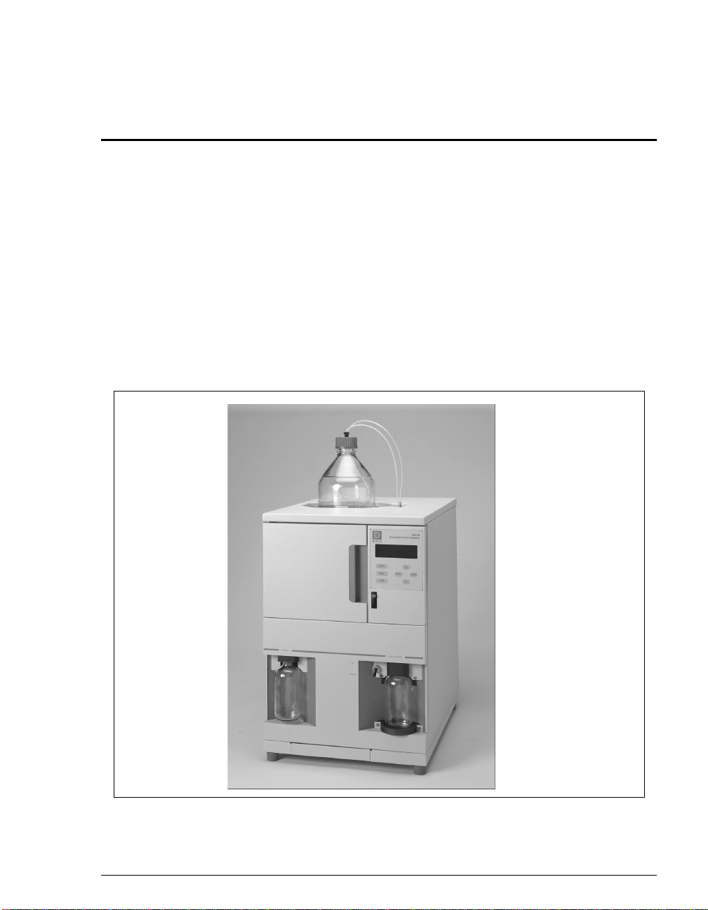
1.1 Overview
®
The ASE
organic o r ino rganic compounds from a varie ty of solid and/or semiso li d sampl es .
The ASE 100 accelerates the traditional extraction process by using solvent at
elevated temperatures and pressures. Pressure is applied to the sample extraction
cell to maintain the heated solvent in a liquid state during the extraction. After
heating, the extract is flushed from the sample cell into a collection bottle and is
ready for analysis.
100 Accelerated Solvent Extractor is a system for extracting either
1 • Introduction
Doc. 031842-01 5/02
Figure 1-1. ASE 100 Accele rated Solvent Extractor
1-1
Page 10

ASE 100 Operator’s Manual
The ASE 100 is designed to minimize the amount of solvent used without
sacrific in g the speed of extracti on or eas e of oper ation. Samples are ex tr act ed on e
at a time, and the extraction process is typically completed in 15 to 25 minutes.
All functions are controlled from the ASE 100 front panel.
Built-in safety diagnostics monitor the system during operation. If a problem
occurs, the front panel displays an error message that identifies the problem. In
addition, the method currently running is aborted and basic system functions are
shut down until the situation is corrected.
The ASE 100 is available in four product versions:
Product Description Part Number
ASE 100 with 10 mL extraction cells 059700
ASE 100 with 34 mL extraction cells 059701
ASE 100 with 66 mL extraction cells 059702
ASE 100 with 100 mL extraction cells 059703
Each ASE 100 is shipped from Dionex with two extraction cells in the sizes
indicated above, one rinse cell in the required size, and 12 collection bottles.
1-2
Ordering Extraction Cells in Other Sizes
The ASE 100 accommodates four extraction cell sizes (10 mL, 34 mL, 66 mL, or
100 mL). To perform an extraction with a cell in any size other than the size
included with your system, order the appropriate cells from Dionex. Cells are
available individually and in packages of six. For cell descriptions and part
numbers, see Appendix D of this manual.
Note that installation of a different extraction cell will require a few additiona l
changes:
Reposition the cell holder to accommodate the new extraction cell size, if
_
required. For instructions, refer to Section B.2.7.
Order a new rinse cell, if required. The rinse cell size must be matched to the
_
extraction ce ll size. For deta ils, see Section 2.1.3.
Before beginning a n e xtr acti on, speci fy the ne w cel l size on the
_
SETUP
screen
(see Section C.1.3).
Doc. 031842 -01 5/ 02
Page 11

1.2 About This Manual
1 • Introduction
Chapter 1
Introduction
Chapter 2
Description
Chapter 3
Operation and
Maintenance
Chapter 4
Troubleshooting
Chapter 5
Service
Appendix A
Specifications
Appendix B
Installation
Presents a brief overview of the ASE 100 Accelerated
Solvent Extractor. Explain s the meaning of safety
messages and icons in the manual and safety labels on the
instrument.
Describes the physical aspects of the ASE 100: the front
panel controls, rear panel connections, electronics, and
mechanical components. Briefly describes the extraction
process.
Describes key operating features and how to create, edit,
and run methods. Lists routine preventive maintenance
requirements.
Lists possible causes of minor problems, as well as stepby-step procedures to resolve them.
Contains step-by-step instructions for routine service and
parts replacement procedures.
Lists the ASE 100 specifications and installation site
requirements.
Describes how to install the ASE 100.
Appendix C
User Inte rface
Doc. 031842-01 5/02
Appendix D
Reordering
Information
Illustrates and describes all of the display screens selected
from the ASE 100 front panel.
Lists names and part numbers for spare parts for the ASE
100.
1-3
Page 12
ASE 100 Operator’s Manual
1.2.1 Typefaces
Uppercase bold t ype indic ates an ASE 100 fr ont panel b utton, the name of
a screen, or an on-screen entry. For example:
Press
_
_
_
RINSE
The
MAIN
Move the cursor to the
to start the rinse cycle.
screen has four options.
field .
SA VE
1.2.2 Saf et y Me ss ages and Notes
This manual contains warnings and precautionary statements that can
prevent personal injury and/or damage to the ASE 100 when properly
followed. Safety messages appear in bold type and are accompanied by
icons, as shown here.
Indicates an imminentl y hazardous situation whic h, i f not avoided, will
result in death or serious injury.
Indicates a potentially hazardous situation which, if not avoided, may
result in death or serious injury.
Indicates a potentially hazardous situation which, if not avoided, may
result in minor or moderate injury.
Indicates that the function or process of the instrument may be
impaired. Operation does not constitute a hazard.
1-4
Doc. 031842 -01 5/ 02
Page 13
1 • Introduction
Messages d’avertissement en français
Signale une situation de danger immédiat qui, si elle n'est pas évitée,
entraînera des blessures graves à mortelles.
Signale une situation de danger potentiel qui, si elle n'est pas évitée,
pourrait entraîner des blessures graves à mortelles.
Signale une situation de danger potentiel qui, si elle n'est pas évitée,
pourrait entraîner des blessures mineures à modérées. Également
utilisé pour signaler une situation ou une pratique qui pourrait
gravement endommager l'instrument mais qui n'entraînera pas de
blessures.
Warnhinweise in Deutsch
Bedeutet unmittelbare Gefahr. Mißachtung kann zum Tod oder
schwerwiegenden Verletzungen führen.
Doc. 031842-01 5/02
Bedeutet eine mögliche Gefährdung. Mißachtung kann zum Tod oder
schwerwiegenden Verletzungen führen.
Bedeutet eine mögliche Gefährdung. Mißachtung kann zu kleineren
oder mittelschweren Verletzungen führen. Wird auch verwen det, wenn
eine Situation zu schweren Schäden am Gerät führen kann, jedoch
keine Verletzungsgefahr besteht.
Informational messages also appear throughout this manual. These are
labeled NOTE and are in bold type.
NOTE NOTES call attention to certain information. They alert
the user to an unexpected result of an action, suggest
how to optimize instrument performance, etc.
1-5
Page 14
ASE 100 Operator’s Manual
1.3 Safety Labels
The TUV GS, C, US Mark safety label and the CE Mark label on the ASE 100
indicate that the ASE 100 is in compliance with the following standards: EN
61010-1:1993 (safety), CAN/CSA-C22.2 No. 1010.1-92 (safety), UL 31011/10.93 (safety), EN 50082-1:1992 (susceptibility), and EN 55011:1991
(emissions).
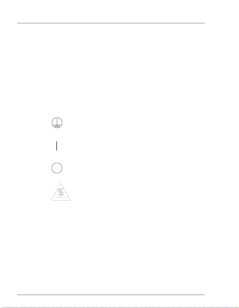
The symbols below appear on the ASE 100 or on ASE 100 labels.
Alternating current
b
Protective conductor terminal
Power supply is on
1-6
Power supply is off
Hot surface
Doc. 031842 -01 5/ 02
Page 15
Section 2.1 and Section 2.2 describe key operating features and components
_
of the ASE 100.
Section 2.3 describes the extraction process of the ASE 100.
_
Section 2.4 describes method control of the ASE 100.
_
Section 2.5 lists the operating parameters for preprogrammed methods.
_
2.1 Operating Features
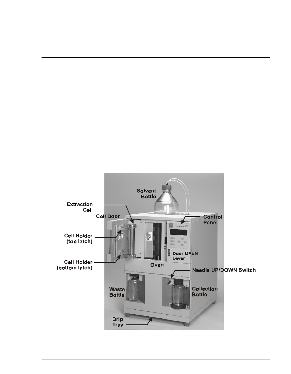
Figure 2-1 illustrates the main operating features of the ASE 100.
2 • Description
Doc. 031842-01 5/02
Figure 2-1. ASE 100 Key Operating Features
2-1
Page 16

ASE 100 Operator’s Manual
Control Panel
The ASE 100 control panel includes a display screen and a membrane keypad
with seven buttons. For more information about the display screen, refer to
Section 2.1.1. For a description of the keypad buttons, refer to Section 2.1.2.
Cell Holder
Before a sample e xtrac tion or a rinse c ycl e is per formed, an e xtr action ce ll or ri nse
cell, respectively , must be installed in the cell holder on the inside of the cell door.
To access the cell holder , pus h do wn on th e
and pull open the door.
Oven
The oven is located behind the cell door. This area also houses the AutoSeal™
tips, which seal the cell during an extraction. A pull-out drip tray is installed
below the o v e n to coll ect an y l iquid l eak s that may occur dur ing an e xt ract ion or a
rinse cycle.
Needle Mechanism
The needle mechanism includes a source needle and two vent needles. The
UP/DOWN
are in the “down” position, they pierce the collection bottle septum, allowing the
extract to f low from the extraction cell into the collection bot t le. The vent needle s
are connected to the w aste bot tle ca p and the sys tem v ent to allow displaced gases
to escape.
toggle switch controls the position of the needles. When the needles
lever (to release the door latch)
OPEN
2-2
Solvent Bottle
A 1-liter or 2-lit er solv ent bottle is in stal led in a re cess on top of the AS E 100. The
recess contains a plastic liner to contain any solvent leaks or spills that may occur.
Waste Bottle
The waste bottle is a 250 mL collection bottle that is sealed with a special cap
assembly. The waste bottle cap is connected to the vent needles. This allows
excess solvent vapors to condense and be collected in the waste bottle before
being vented out the ASE 100 rear panel.
Collection Bottle
After each extraction, the 250 mL collection bottle contains solvent and the
analytes extracted from the sample.
Doc. 031842 -01 5/ 02
Page 17
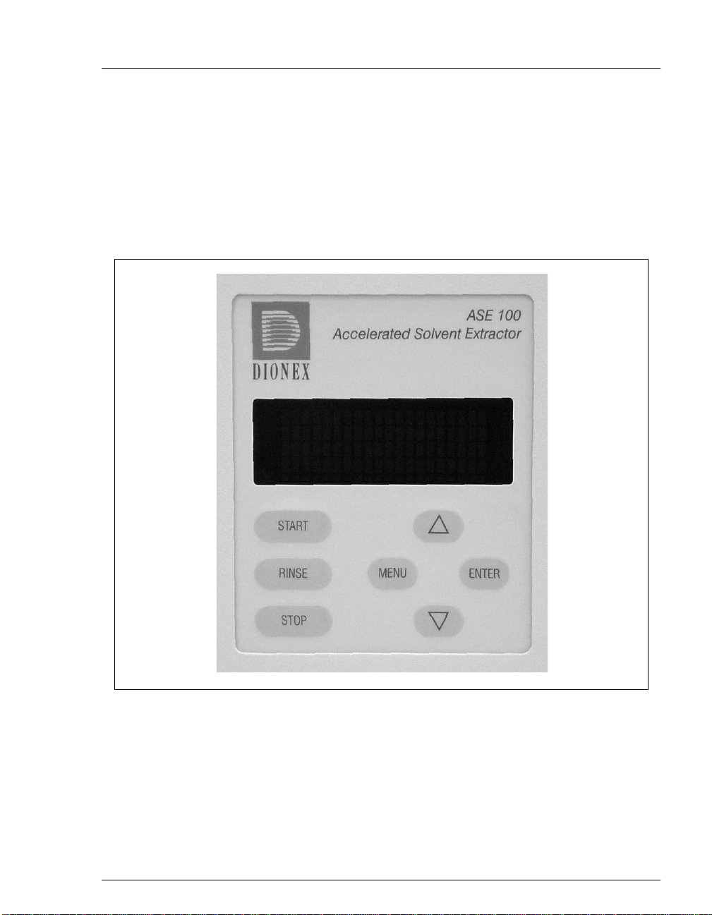
2.1.1 Control Panel Screen
The control panel scree n disp lays s tatus an d opera ting i nforma tion f or th e
ASE 100. Use the screen, in conjunction with the control panel keypad
(see Section 2.1.2), to control ASE 100 operation.
You can edit any f ield on the screen that contains a blinking curso r . A f ield
without a blinking cursor is for display only.
2•Description
Doc. 031842-01 5/02
Figure 2-2. ASE 100 Control Panel
2-3
Page 18
ASE 100 Operator’s Manual
2.1.2 Contro l Panel Keypad
Use the control panel k e ypad, in c onjuncti on with t he contr ol panel screen
(see Section 2.1.1), to control ASE 100 operation.
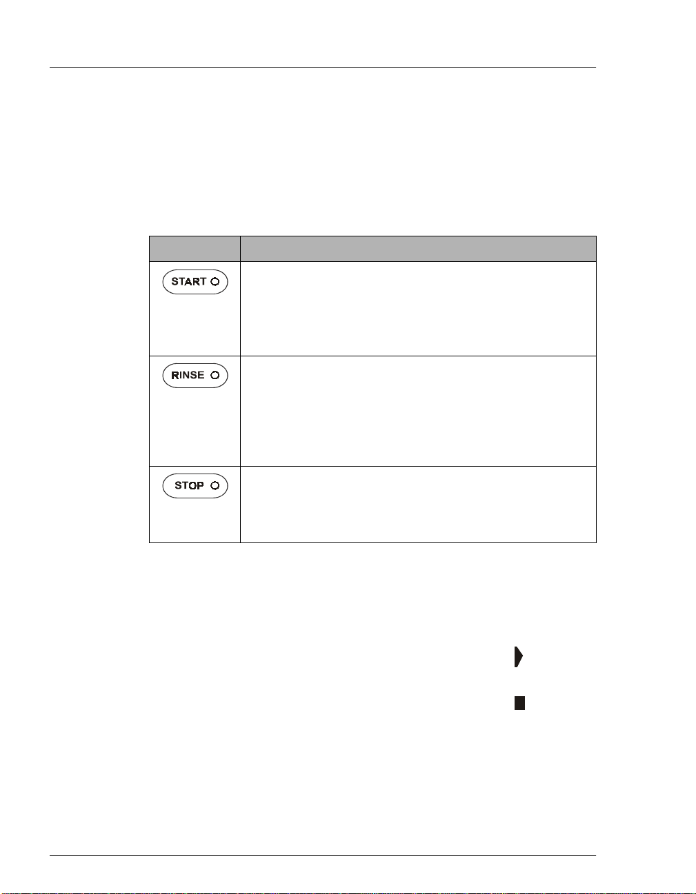
Three of the control panel buttons (
START, RINSE
, and
STOP
) let you
directly control the most frequently used functions.
Button Function
Starts the currently selected method. The LED starts flashing
when the oven is within 5 °C of the set point. During the
method run, the LED is lighted, but does not flash. When the
method finishes running (or is aborted), three beeps are
emitted and the LED turns off.
Starts a rinse cycle in which about 5 mL of solv ent is p umped
through the system. During the rinse cycle, the LED is
lighted. When the rinse cycle is complete (or is aborted),
three beeps are emitted and the LED turns off.
Always install a rinse cell and a rinse bottle before
Note:
starting a rinse cycle; see Section B.2.6 for instructions.
Interrupts the currently running method or rinse cycle and
displays the
LED. The LED turns off when you select an option on the
ABORT
ABORT
screen; see Section 3.6 for details.
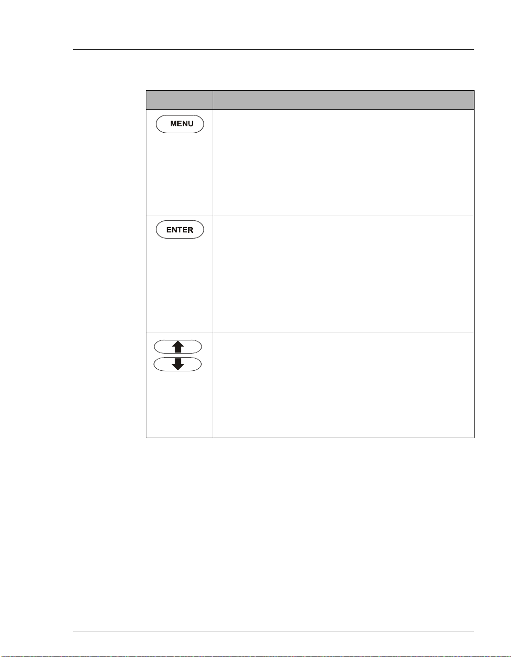
The four screen na viga tion b utt ons (
screen. Pressing the button lights the
MENU, ENTER
, the up arrow, and the
down arrow) are used in conjunction with the ASE 100 display to access
less frequently used functions. The action of the navigation keys depends
on whether the cursor is in
normal
mode or
editing
mode:
2-4
In
normal
mode, the cursor does no t blink and looks like
this.
In
editing
mode, the cursor blinks and looks like this.
You can edit any field that contains a blinking cursor.
Doc. 031842 -01 5/ 02
Page 19
2•Description
Button Function
Normal mode:
Exits the screen currently displayed and
returns to the screen one level up in the hierarchy. For
example, if the
pressing
MENU
METHOD EDITOR
returns you to the
screen is displayed,
screen. See
MAIN
Figure C-1 for an overview of the screens.
Editing mode:
Rejects your editing change in a field and
reverts to the previously selected parameter.
Normal mode:
pointing to. On the
Selects the field the cursor is currently
MAIN
or
DIAGNOSTICS
screen, this
selects and displays a different screen. On other screens,
pressing
ENTER
moves the cursor from the left margin to the
first field in that line that can be edited; it also changes the
normal cursor into the blinking editing cursor.
Editing mode:
Saves the parameter currently displayed in a
field.
Normal mode:
Moves the cursor, in the direction of the arrow,
to the next selectable line on the display (if any).
Editing mode:
Pressing and releasing an arrow button
displays the next or previous parameter or numeric value
allowed for the field. Pressing and holding down an arrow
button moves the cursor continuously through the allowed
settings.
Doc. 031842-01 5/02
2-5
Page 20
ASE 100 Operator’s Manual
2.1.3 Extrac tion Cells and Rinse Cells
Always tighten cell end caps by hand. Use of a wrench or other
tool can damage the cell, as well as the seal inside the cell cap.
Extraction Cells
ASE 100 extraction cells are available in four sizes: 10 mL, 34 mL,
66 mL, and 100 mL. Interchangeable end caps scre w ont o each e nd of t he
cell body. Each cell end cap contains a stainless steel frit and a seal.
During a run, the cell caps are compressed to form a tight seal between
the caps and the cell body.
An O-ring is installed on the outside of each cell cap. Teflon
®
(P/N 049457, pkg. of 50) are standard. Viton
O-rings (P/N 056325, pkg.
®
O-rings
of 50) are available for high temperature extractions, such as dioxins.
If a Viton (black) O-ring is installed on the outside of the cell
cap, do not use acetone as the solvent for an extraction.
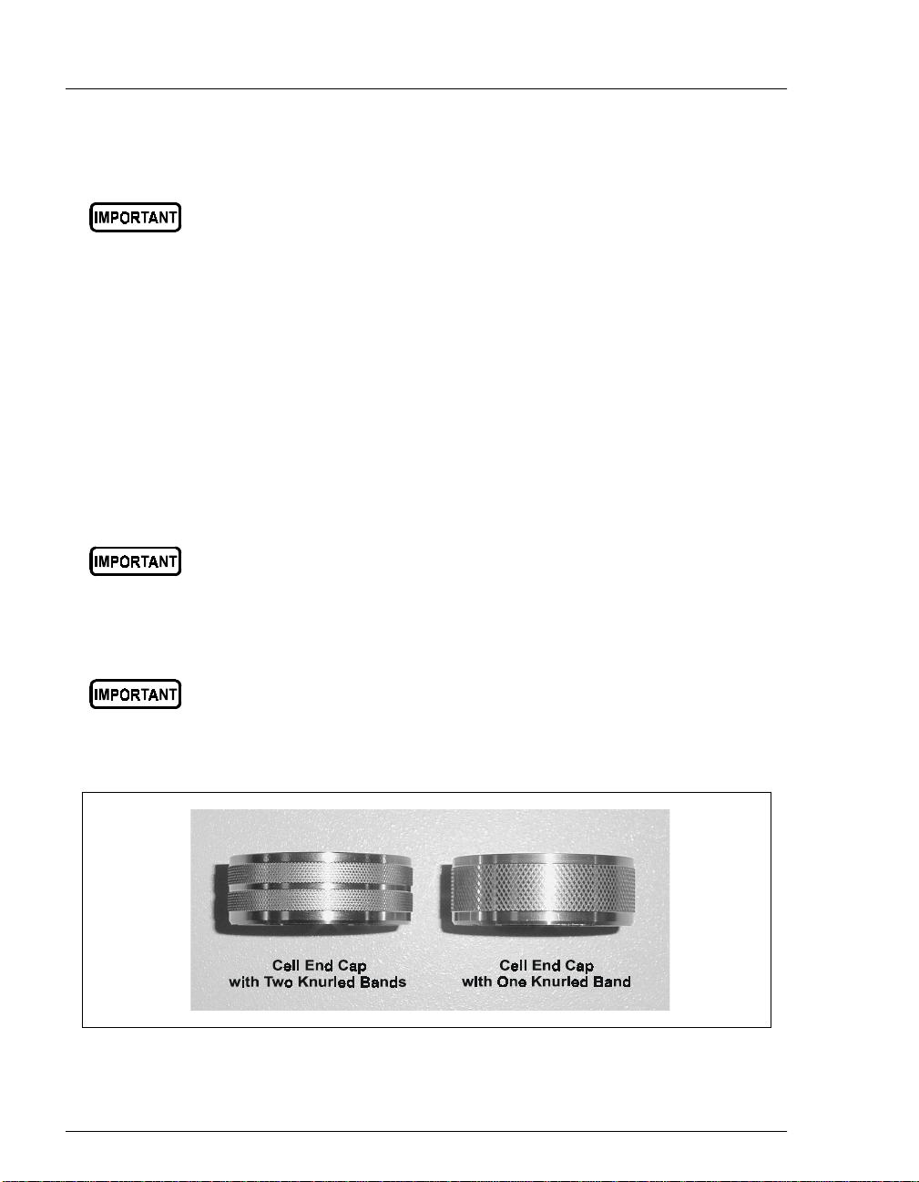
Note that only cell end caps with two knurled bands can be used with the
ASE 100 (see Figure 2-3).
Cell end caps with two knurled bands can be installed in either
the ASE 100 or ASE 300 Accelerated Solvent Extractor.
However, end caps with one knurled band can only be used
with the ASE 300.
2-6
Figure 2-3. Knurling on Cell End Caps
Doc. 031842 -01 5/ 02
Page 21

Rinse Cells
During a rinse cycle, solvent passes directly through the blue rinse cell
and into the collection bottle. For more information about rinse cycles,
see Section 3.1.7 and Section B.2.6.
The rinse cell size ( short, medi um, or long) mus t be matche d to the si ze of
the extraction cell, as indicated in the table below.
Use this rinse cell: With this extraction cell:
Short (P/N 060174) 10 mL, 34 mL
Medium (P/N 060175) 66 mL
Long (P/N 060176) 100 mL
2.1.4 Collection Bottle
The 250 mL collection bottle (P/N 056284, pkg. of 12) is made of clear
glass. The collection bottle cap contains a solvent-resistant septum.
During an extraction, the needle mechanism is lowered so that the needles
pierce the septum. This creates a liquid flow path from the extraction cell
to the collection bottle.
2•Description
Doc. 031842-01 5/02
After an extraction, the bottle contains solvent and the analytes extracted
from the sample. Refer to S ection 3.5 for post-extraction procedures.
s with any glass object, the collection bottle may become
A
damaged after repeat ed use. Before each extraction, carefully
inspect the collection b ottle for chips, scratches, or cracks. If
you notice any signs of damage, dispose of the bottle and
install a new one.
Replace the septum (P/N 04 9464, pkg. of 72) in the bottle cap
after each extraction. Using the septum more than once may
cause loss of sample and damage to the instrument.
2-7
Page 22
ASE 100 Operator’s Manual
2.1.5 Solvent Bottle
The ASE 100 Ship Kit (P/N 059397) includes a 2-liter glass bottle with
shatterproof plastic coating (P/N 045901) and a bottle cap assembly
(P/N 051977) with tubing and fitt ings f or the inl et and outle t conne ction s.
For instructions on how to install the solvent bottle, see Section B.2.4.
Use only Dionex solvent bottles (1-liter, P/N 045900; 2-liter,
P/N 045901). These are glass bottles with a shatterproof plastic
coating. To prevent operator injury, make sure the pressure
applied to the bottles does not exceed 0.07 MPa (10 psi).
Utilisez uniquement des réservoirs à solvant Dionex (1 litre,
N/P 045900; 2 litres, N/P 045901). Ce sont des réservoirs en
verre à revêtement incassable en plast ique. Veillez à ce que la
pression exercée sur ces réservoirs ne dépasse pas 0,07 MPa.
Verwenden Sie ausschließlich die Lösemittelbehälter von
Dionex (1-Liter, Bestell-Nr. 045900 ; 2-Liter, Bes tell-Nr. 04 5901).
Dabei handelt es sich um Glasbehälter mit einer
splittersicheren Plastikbeschichtung. Vergewissern Sie sich,
daß der Druck, der auf die Behälter ausgeübt wird, 0,07 MPa
nicht übersteigt.
2-8
NOTE Never fi ll the solvent bottle or disconnect the tubing
connections to the
(see Figure 3-1) when the system is performing an
extraction or a rinse cycle. During these times, the
solvent bottle is pressurized. If you remove the
bottle cap when the solvent bottle is pressurized, the
ASE 100 may not operate to specification.
SOLVENT
and
GAS
connectors
Doc. 031842 -01 5/ 02
Page 23

2.1.6 Waste Bottle
A 250 mL collection bottle (P/N 056284, pkg. of 12) serves as the waste
bottle (see Figure 2-1) for the system.
Three vent lines, one from the pressure relief valve and two from the
needle mechanism, are connec ted to the w aste bottle cap. The waste bottl e
collects the small amounts of condensed solvent vented through these
lines.
A vent outlet line is connected to the wast e bot tl e cap, also. Gas is vented
out this line to the rear pan el of the ASE 100. F or instal lation ins tructi ons,
see Section B.2.1.
NOTE Check the waste bottle regularly and empty
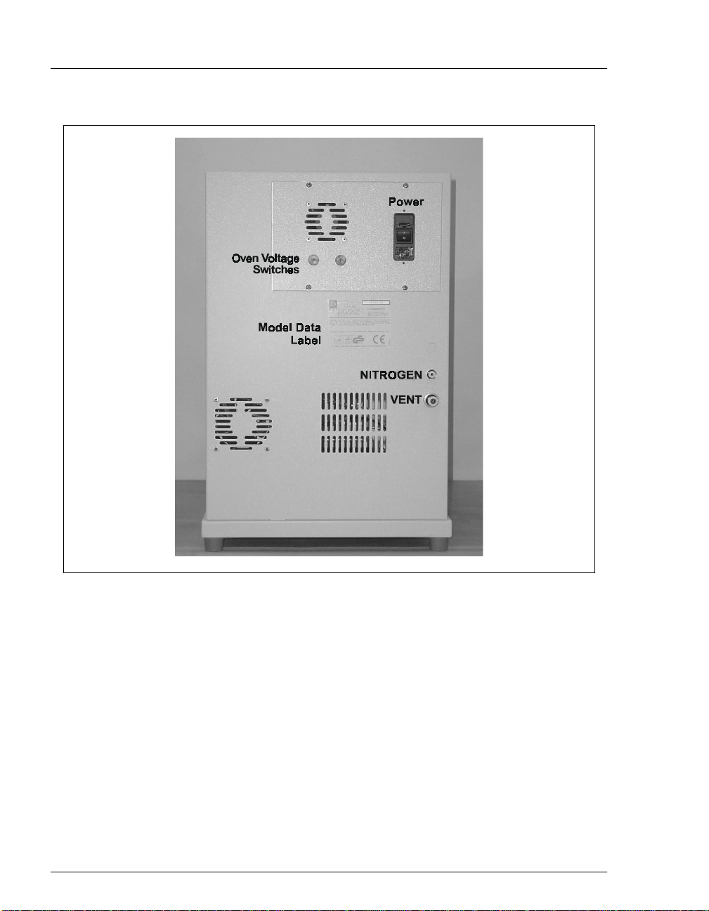
2.2 Rear Panel
Figure 2-4 illustrates th e rear panel of the ASE 100.
2•Description
whenever necessary.
The
_
_
_
_
_
POWER
The power re cepta cle al so inc ludes the fuse h older. For instructi ons on how to
replace the fuses, see Section 5.11.
The oven voltage switches must be set to match the voltage from the power
source at the ASE 100 installation site. For instructions on how to set the
switches, see Section B.2.2.
The
NITROGEN
between 1.03 and 1.38 MPa (150 to 200 psi). For installat io n i nst ruc ti ons , see
Section B.2.1.
The
VENT
installation instructions, see Section B.2.1.
The model data label list s fuse and po wer informati on, as well as the ASE 100
serial number. You will be asked to provide the serial number when ordering
replacemen t parts for the system.
switch provides on/off control of the main power for the system.
connector is connected to a nitrogen supply regulated to
connector provides a connection for the vent outlet line. For
Doc. 031842-01 5/02
2-9
Page 24
ASE 100 Operator’s Manual
2-10
Figure 2-4. ASE 100 Rear Panel
Doc. 031842 -01 5/ 02
Page 25

2.3 Extraction Process
Before starting an extraction, perform the following steps. Re fer to Chapter 3 for
detailed instructions for each step.
Prepare sample and load it into the extraction cell.
_
Set up a method.
_
2•Description
Press the
_
Verify that the system
_
on the
Place the collection bottle, with the bottle cap screwed on, in the holder.
_
Lower the needle mechanism.
Place the extraction cell in the cell holder and close t he cell door.
_
Press
_
From this point, the ASE 100 automatically performs the extraction process. An
extraction consists of six main steps:
Filling the cell with solvent
_
Heating the cell (equilibration)
_
Static extraction
_
Flushing with fresh solvent
_
Purging solvent from the system
_
End relief
_
START
START
START
button.
STATUS
button is flashing.
to begin the run.
is
OVEN READY
(see Figure 2-5) and the LED
Doc. 031842-01 5/02
2-11
Page 26
ASE 100 Operator’s Manual
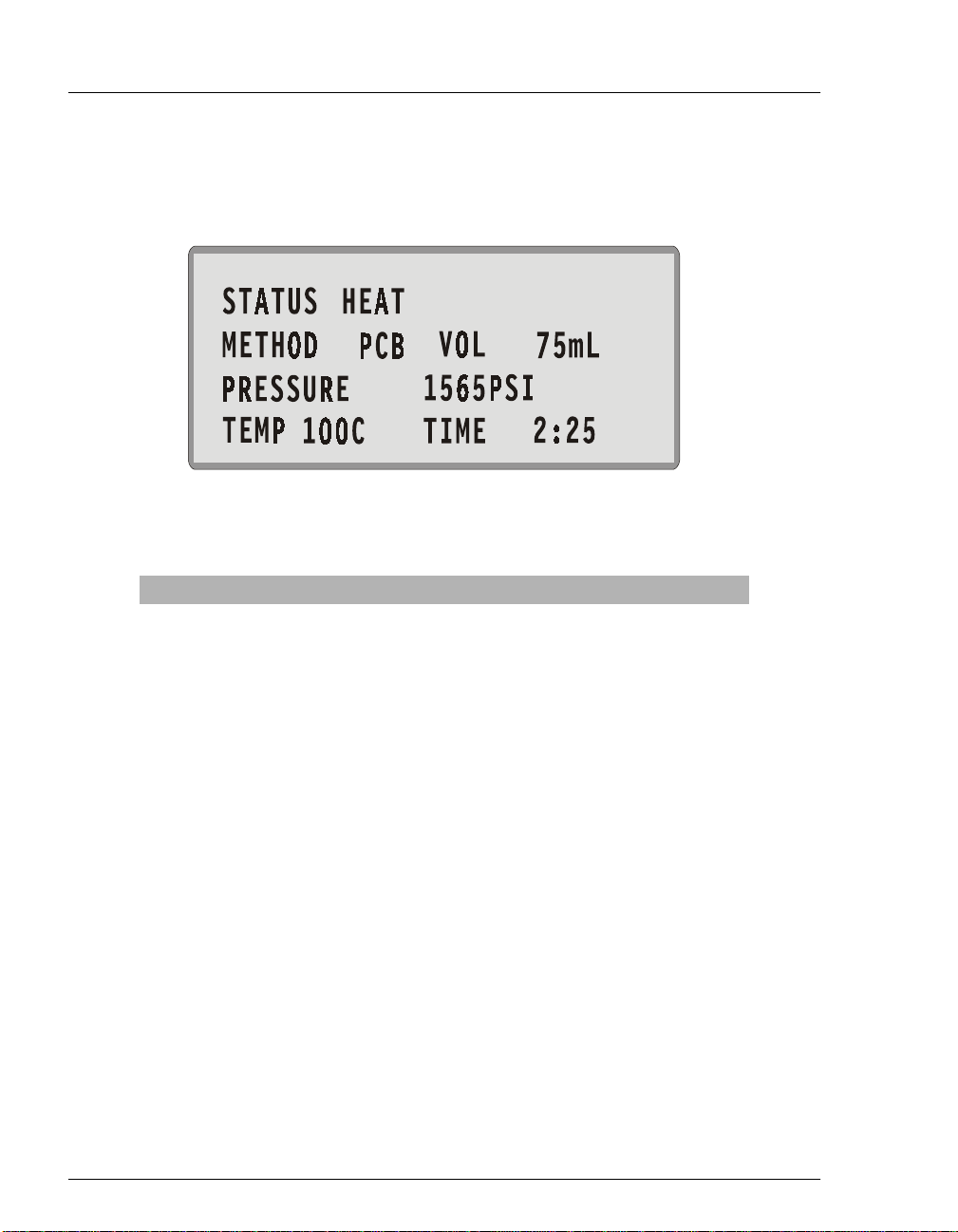
You can monitor the progress of an extraction on the
STATUS
screen (a
MAIN
screen option). Operating parameters are updated in real time. Figure 2-5
illustrates a typical
Parameter Description
STATUS
METHOD
VOL
PRESSURE
TEMP
TIME
STATUS
Table 2-1. Status Screen Parameters
screen. Table 2-1 describes the screen parameters.
Figure 2-5. Status Screen
The method step in progress, if any, or the current
system status. If the latter is indicated, the
STATUS
will display one of the following descriptions: Initialize,
Idle, Load, Fill, Preheat, Heat, Oven Wait, Ov en Ready,
Static, Flush, Purge, Relief, Unload, Rinse, or Abort. If
the status is Static or Flush, the cycle number is
indicated.
The name or number of the current method.
The approximate volume of solvent (in mL) delivered
by the pump since the method started running.
The current pressure reading. Select the unit of measure
on the
SETUP
screen (see Section C.1.3).
The temperature specified in the method.
Elapsed time (in minutes and seconds) since the method
started running.
field
2-12
Doc. 031842 -01 5/ 02
Page 27

2.4 Method Control
2•Description
A
method
defines all of th e timed ev ents that occur during a sample ext raction (see
Table 2-2). There are two types of methods:
Preprogrammed
_
methods are application-speci fic meth ods created by Dionex.
These methods cannot be changed or deleted by the user. For a list of the
parameters for each preprogrammed method, see Section 2.5.
_
Custom
methods are customer-pr ogrammabl e methods. A ll custom m ethods
initially contain the default method parameters. These methods can easily be
modified ( i.e ., c ust om iz ed) by the user as required. For instruction s o n how to
edit a custom method, see Section 3.2.
Parameter Function Value Range
TEMPERATURE
STATIC TIME
FLUSH
VOLUME
Temperature at which to heat the extraction cell. Off, 40 to
200°C
(default=100)
Static solvent extraction time. 0 to 99 min
(default=5)
Amount of solvent to flush through the
extraction cell after the static heating step. The
FLUSH VOLUME
of the cell volume; for example, if the
VOLUME
a 10 mL cell, 17 m L i s flus hed t hr oug h a 34 mL
cell, and so on.
is set to 50%, 5 mL is flushed through
is expressed as a percentage
FLUSH
0 to 150% vol
in 5% increments
(default=60)
PURGE TIME
STATIC CYCLE
Doc. 031842-01 5/02
Amount of time the cell is purge d with nitro gen . 20 to 900 sec
(default=100)
Number of times the static heating and flushing
steps are performed. When more than one cycle
is specified, the flush volume is divided among
the cycles.
Table 2-2. Method Parameters
1 to 5
(default=1)
2-13
Page 28

ASE 100 Operator’s Manual
2.5 Preprogrammed Methods
To enable you to quickly produce res ul ts wit h t he ASE 100, Dionex pro v ide s nine
preprogrammed methods. These methods are designated by three-letter
abbrevia ti ons (se e the table below).
Preprogrammed Method Method Name
Semivolatiles BNA
Total Fat (crude) FAT
Chlorinated Herbicides HRB
Organochlorine Pesticides OCP
Organophosphorous Pesticides OPP
Polychlorinated Biphenyls PCB
Dioxins and Furans PDF
Polymer Additives PPE
2-14
Total Petroleum Hydrocarbons TPH
The remainder of this section lists the operating conditions and recommended
solvent for each preprogrammed method. You cannot edit or delete a
preprogrammed method.
BNA (Semivolatiles) Method Parameters
Solvent MeCl2/Acetone (1:1, v/v)
Temperature 100 °C
Static Time 5 min
Flush Volume 60%
Purge Time 100 sec
Static Cycle 1
Doc. 031842 -01 5/ 02
Page 29

2•Description
FAT (Total Fat) Method Parameters
Solvent Hexane/Acetone (4:1)
Temperature 125 °C
Static Time 5 min
Flush Volume 100%
Purge Time 60 sec
Static Cycle 3
HRB (Chlorinated Herbicides) Method Parameters
Solvent MeCl2/Acetone (1:1) with 1%
H
3PO4
Temperature 100 °C
Doc. 031842-01 5/02
Static Time 5 min
Flush Volume 60%
Purge Time 100 sec
Static Cycle 1
OCP (Organochlorine Pesticides) Method Parameters
Solvent Hexane/Acetone (1:1, v/v)
Temperature 100 °C
Static Time 5 min
Flush Volume 60%
Purge Time 100 sec
Static Cycle 1
2-15
Page 30

ASE 100 Operator’s Manual
OPP (Organophosphorous Pesticides) Method Parameters
Solvent MeCl2/Acetone (1:1, v/v)
Temperature 100 °C
Static Time 5 min
Flush Volume 60%
Purge Time 100 sec
Static Cycle 1
PCB (Polychlorinated Biphenyls) Method Parameters
Solvent Hexane
Temperature 100 °C
Static Time 5 min
Flush Volume 60%
Purge Time 100 sec
Static Cycle 1
PDF (Dioxins and Furans) Method Parameters
Solvent Toluene
Temperature 200 °C
Static Time 5 min
Flush Volume 60%
Purge Ti me 100 sec
Static Cycle 1
2-16
Doc. 031842 -01 5/ 02
Page 31

PPE (Polymer Additives) Method Parameters
Solvent 2.5% Cyclohexane in
Isopropyl Alcohol
Temperature 140 °C
Static Time 3 min
Flush Volume 100%
Purge Time 60 sec
Static Cycle 3
TPH (Total Petroleum Hydrocarbons) Method Parameters
Solvent MeCl2/Acetone (1:1, v/v)
Temperature 175 °C
2•Description
Static Time 5 min
Flush Volume 60%
Purge Time 100 sec
Static Cycle 1
Doc. 031842-01 5/02
2-17
Page 32

ASE 100 Operator’s Manual
2-18
Doc. 031842 -01 5/ 02
Page 33

3 • Operation and Maintenance
3.1 Preparing to Run an Extraction
3.1.1 Selecting and Preparing Solvent
Do not use solvents with an autoignition point of 40 to 200 °C
(104 to 392 °F). The table below is a partial list of solvents that
should not be used with the ASE 100. If you have a question
about solvent suitability, contact Dionex.
Solvents Not to Use Autoignition Point
Carbon disulfide: CS
Diethylether: (C
1,4-dioxane: C
2
O180
2H5)2
4H8O2
N'utilisez pas de solvants ayant un point d'auto-inflammation
entre 40 et 200 °C. Le tableau ci-dessous donne la liste de
quelques solvants qui ne devraient pas être utilisés avec l'ASE
100. Contactez Dionex si vous avez des questions sur le
caractère approprié d'un solvant.
100 °C (212 °F)
180 °C (356 °F)
C (356 °F)
°
Doc. 031842-01 5/02
Solvants à ne pas utiliser Point d'auto-infl amm atio n
Disulfure de carbone: CS
Éther diéthylique: (C
1,4-dioxa ne: C
2H5)2
4H8O2
2
100 °C
O180 °C
180 °C
3-1
Page 34

ASE 100 Operator’s Manual
Verwenden Sie keine Lösungsmittel, deren
Selbstentzündungstemperatur bei 40° bis 200°C liegt. Die
untenstehende Tabelle zeigt einige Lösungsmittel, die Sie nicht
mit dem ASE 100 verwenden sollten. Bei Fragen zur Eignung
von Lösungsmitteln wenden Sie sich bitte a n Dionex.
Nicht zu verwendende
Lösungsmittel
Kohlendisulfid: CS
Diethyläther: (C
1,4-dioxan: C
When devel oping a ne w ex traction metho d, select a sol vent or solvent
_
2H5)2
4H8O2
2
O 180 °C
Selbstentzündungstemperatur
100 °C
180 °C
mixture that has a high solubility for the analytes of interest, but not
for the sample matrix. If you have been using another extraction
method (Soxhlet, for example), use the same solvent with the ASE
100 that you used with the other method.
Before running a prepr ogr ammed me tho d, r efe r to Section 2.5 for the
_
recommended solvent.
Use HPLC- or pesticide-grade solvents.
_
Use organic or aqueous solvents.
_
Use single- or multiple-component solvents.
_
Weak acids and bases (pH >2 or pH <11) or other noncorrosive
_
additives can be used, but add them in small percentages (<5% by
volume) to the solvent system. Do not use nitric, hydrochloric, or
sulfuric acid with the ASE 100.
3-2
After extracting with acidic solvents or basic solvents, rinse
the system with eit her 100% organic solvent (e. g., acetone or
methanol) or distilled water before overnight shutdown.
Solvents do no t g enerally need to be degassed. Deg as solvents only if
_
the analyte of interest oxidizes easily.
Do not use acetone if the O-ring on the outside of the
extraction cell cap is Viton (black).
Doc. 031842 -01 5/ 02
Page 35

3.1.2 Filling the Solvent Bottle
Use only Dionex solvent bottles (1-liter, P/N 045900; 2-liter,
P/N 045901). These are glass bottles with a plastic,
shatterproof coating. Make sure the pressure applied to the
bottles does not exceed 0.07 MPa (10 psi).
Utilisez uniquement des réservoirs à solvant Dionex (1 litre,
N/P 045900; 2 litres, N/P 045901). Ce sont des réservoirs en
verre à revêtement incassable en plas tique. Veillez à ce que la
pression exercée sur ces réservoirs ne dépasse pas 0,07 MPa.
Verwenden Sie ausschließlich die Lösemittelbehälter von
Dionex (1-Liter, Bestell-Nr. 045900 ; 2-Liter, Bes tell-Nr. 04 5901).
Dabei handelt es sich um Glasbehälter mit einer
splittersicheren Plastikbeschichtung. Vergewissern Sie sich,
daß der Druck, der auf die Behälter ausgeübt wird, 0,07 MPa
nicht übersteigt.
NOTE Never fi ll the solvent bottle or disconnect the tubing
connections to the
(see Figure 3-1) when the system is performing an
extraction or a rinse cycle. During these times, the
solvent bottle is pressurized. If you remove the
bottle cap when the solvent bottle is pressurized, the
ASE 100 may not operate to specification.
3 • Operation and Maintenance
SOLVENT
and
GAS
connectors
Doc. 031842-01 5/02
1. Fill the sol vent bottle with prepared solvent to the level indicated in
Figure 3-1.
If you plan to run a preprogrammed method, refer to Section 2.5 for
the recommended solv ent. I f you pla n to run a custom method , re vie w
the solvent se lection guidelines in Section 3.1.1.
NOTE The solvent level in the bottle must remain below the
gas inlet line. This prevents solvent from coming
into contact with the pneumatic valves.
2. Place the bottle in the recess on top of the system.
3-3
Page 36

ASE 100 Operator’s Manual
3. Insert the solvent outlet line extending from the underside of the
bottle cap assembly into the bottle (see Figure 3-1). Make sure the inline filter rests on the bottom of the bottle. (This prevents air from
being drawn through the line.)
4. Hand-tighten the re d lock ring cap securely over the stopper.
NOTE Always connect the outlet line to the
connector first, and then the inlet line to the
connector. Reverse this order when disconnecting
the lines. It is not necessary to disconnect the solvent
and gas lines before refilling the solvent bottle.
SOLVENT
GAS
3-4
Figure 3-1. Solvent Bottle Connections (Top view)
Doc. 031842 -01 5/ 02
Page 37

3.1.3 Preparing the Sample
Some samples must be mixed with a drying or dispersing agent before
being loaded into the cell. If you have successfully followed a particular
sample pretreatment procedure for another extraction method (Soxhlet,
for example), us e the same procedu re with the ASE 100. If you hav e ne ver
run an extraction before or if you are preparing a new sample, follow the
guidelines here.
Drying or Dispersing Agent Selection Guidelines
The sample preparation guidelines in the next section mention two
_
drying and dispers ing ag ents: sodi um sulf at e (Na
diatomaceous earth (DE). DE is easier to work with than sodium
sulfate; it dries samples more quickly, provides a cleaner transfer of
the mixtures to the cell, and extracts well. Sodium sulfate is more
readily available, but it tends to clump the samples and this makes
transfer more difficult.
The use of sodium sulfat e wit h very wet samples (30% moistu re) can
_
clog the frits in the cell with recrystallized sodium sulfate. This is
most likely to occur when using a mixed solvent with acetone or
methanol. To prevent clogging, substitute DE as a drying agent and
mix it with the sample before loading into the extraction cell. Or, use
DE as a drying agent in the cell for all levels of moisture.
3 • Operation and Maintenance
) and pelletized
2SO4
Doc. 031842-01 5/02
To ensure that very wet samples are completely dried (regardless of
_
which drying agent is used), add sodium sulfate to the bottles after
collection and then pass the extracts through either a drying column
or a drying cartridge. At the temperatures used during ASE 100
extractions, m ore water is co- extracted than with other extraction
procedures. To ensure good analyte recovery, thoroughly rinse the
sodium sulfate from the bottle and the cleanup column.
3-5
Page 38

ASE 100 Operator’s Manual
Sample Preparation Guidelines
The mixtures here are recommendations; adjust the proportions as
required for your extraction.
If the sample appears dry, use one of these mixtures:
_
4 grams sample to 1 gram DE
4 grams sample to 4 grams Na
2SO4
Mix the sample and the DE or Na2SO4 thoroughly in a small bottle,
beaker, or mortar .
If the sample appears wet, use one of these mixtures:
_
4 grams sample to 2 grams DE
4 grams sample to 8 grams Na
2SO4
Mix the sample and the DE or Na2SO4 thoroughly in a small bottle,
beaker, or mortar .
If the sample is pure liquid, use 5 grams sample to 3 grams DE.
_
Fill the cell with DE and then add the sample.
3-6
Doc. 031842 -01 5/ 02
Page 39

3.1.4 Installing the Cell Filter
A disposable filter must be installed in the bottom end of the extraction
cell before sample is loaded. The filter prevents blockage of the stainless
steel frit in the bottom cap.
There are two types of cell filters:
3 • Operation and Maintenance
_
Cellulose
filters (P/N 056780, pkg. 100) are appropriate for most
extraction m ethods that use organic solvents. The ASE 100 Ship Kit
(P/N 059397) includes a package of cellulose filters.
Glass-fiber
_
filters (P/N 056781, pkg. 100) are recommended for
aqueous extractions, where cellulose may provide inadequate
filtration or may interfere with the analytical technique.
1. Screw a cell cap onto the bottom of the cell body. (There is a groove
around the top of the cell body, but no groove around the bottom.)
Hand-tighten the cap.
Always tighten the cell end caps by hand. Use of a wrench or
other tool can damage the cell, as w ell as the seals inside t he
caps.
Always tighten the bottom cell cap onto the cell before
installing the cell filter. If you install the filter first, the cap will
not seal properly and will allow leaks.
Doc. 031842-01 5/02
3-7
Page 40

ASE 100 Operator’s Manual
2. Follow the steps below to install the cell filter.
Insert a cellulose or
glass-fiber filter into
the cell at a slight
angle.
Position the filter
insertion tool
(P/N 056929) over the
filter.
Slowly push the
insertion tool
straight into the cell.
3-8
Push down on the
filter until it is in full
contact with the end
cap frit. (End cap not
shown in photo.)
Doc. 031842 -01 5/ 02
Page 41

3.1.5 Filling the Cell
NOTE When filling the cell with sample, keep the threads
on the cell body and end cap as clean as possible to
prevent thread fouling and extend the life of the cell.
Also make sure that the ends of the cell body and the
seals in the end caps are clean; if debris remains
here, it will damage the cell body and/o r allow l eaks
during the extraction.
1. Carefully load the sample into the top of the extraction cell, using the
funnel (P/N 056699 ) pro vided i n the ASE 10 0 Ship Kit (P/N 0593 97).
3 • Operation and Maintenance
2. (
Optional
) To reduce the amount of solvent used during the
extraction, fill any void volume in the cell with an inert material such
as Ottawa sand (Fisher S23-2).
3. Using a soft brush or cloth, wipe all debris off the threads.
4. Screw the top cap onto the cell body. Hand-tighten the cap.
Always tighten the cell caps by hand. Use of a wrench or other
tool can damage the cell, as well as the seals inside the cell
caps.
5. Check the ends of each end cap to verify that the O-rings are in place
and are in good condition (see Figure 3-2). If an O-ring is discolored
or has a hole size of less than 0.5 mm, replace it:
a. Use a small flathead screwdriver (P/N 046985) to remove the old
O-ring from the cell cap.
b. Place a new O-ring over the openi ng in the end of the cel l cap and
press it into place, using the O-ring insertion tool (P/N 049660).
Doc. 031842-01 5/02
3-9
Page 42

ASE 100 Operator’s Manual
Figure 3-2. Inspecting Cell O-Rings
3-10
Doc. 031842 -01 5/ 02
Page 43

3 • Operation and Maintenance
3.1.6 Installing the Collection Bottle
1. Toggle t he nee dle s witch o n th e fr ont pa nel ( see Fi gure 3-3) to the UP
position.
2. Place a 250 mL collection bottle (P/N 056284, pkg. of 12), with the
bottle cap screwed on, in the collection bottle holder (see Figure 3-3).
3. Toggle the needle switch to the
NOTE Reverse the steps above to remove the collection
bottle from the system.
Figure 3-3. Installing the Collection Bottle
DOWN
position.
Doc. 031842-01 5/02
NOTE Verify that the waste bottle is installed (see
Section B.2.5).
3-11
Page 44

ASE 100 Operator’s Manual
3.1.7 Rinsing/Priming the System
During a rinse cycle, approximately 5 mL of solvent is pumped through
the system. Run a rinse cycle at the following times:
After initial setup
_
After refilling the solvent bottle
_
After changing solvents (rinse twice to remove all of the previous
_
solvent)
When the solvent lines contain bubbles
_
After a run is aborted
_
Before shutting down the system, if an extraction used acidic solvents
_
or basic solvents (see Section 3.8)
After a shutdown of more than one day (see Section 3.8)
_
Before starting a rinse cycle:
Check that the rinse cell size is matched to the extraction cell size.
_
Adjust the cell holder to accommodate the rinse cell, if necessa ry.
_
Install the rinse cell in the cell holde r.
_
Close the cell door.
_
When you are ready, press the
detailed instructions, refer to Section B.2.6.
RINSE
button to start the rinse cycle. For
3-12
Doc. 031842 -01 5/ 02
Page 45

3 • Operation and Maintenance
3.2 Editing a Custom Method (1–24)
If the ASE 100 preprogrammed methods (see Section 2.5) are not suitable for a
particular e xtracti on, edit one of the 24
custom
All parameters in these methods are initially set to their default values. You can
create a new method by editing either a custom method that still contains the
default parameters or a custom method that you previously edited. The edited
method can be saved to a new method number, if desired.
Before beginnin g, re vi ew the method de v elopment gui delines in Secti on 3.3. For a
list of the values allowed for metho d parameters, see Table 3-3.
Parameter Function Value Range
methods provided with the sys tem.
TEMPERATURE
STATIC TIME
FLUSH
VOLUME
PURGE TIME
STATIC CYCLE
Temperature at which to heat the cell. Off, 40 to
200°C (default
= 100)
Static solvent extraction time. 0 to 99 min
(default = 5)
Amount of solvent to flush through the
extraction cell after the static heating step,
expressed as a percentage of the cell volume.
For example, if the
50%, 5 mL is flushed through a 10 mL cell , 17
mL is flushed through a 34 mL cell, and so on.
Amount of time the cell is purged with
nitrogen. We recommend 40 to 80 seconds fo r
a 10 mL cell, 70 to 110 seconds for a 34 mL
cell, 160 to 200 seconds for a 66 mL cell, and
250 to 290 seconds for a 100 mL cell.
Number of times the static heating and flushing
steps are performed. When more than one
cycle is specified, the flush volume is divided
among the cycles.
Table 3-3. Method Parameters
FLUSH VOLUME
is set to
0 to 150% vol
in 5% increments
(default = 60)
20 to 900 sec
(default = 100)
1 to 5
(default = 1)
Doc. 031842-01 5/02
3-13
Page 46

ASE 100 Operator’s Manual
To edit a custom method (for example, method 1):
1. Press
MENU
to display the
Figure 3-4. Main Screen
MAIN
screen.
2. Move the cursor to the
The
METHOD EDITOR
Figure 3-5. Method Editor Screen (Additional text shown)
NOTE For convenience, Figure 3-5 illustrates all of the
method parameters. In reality, the screen displays
no more than four lines of text at once. To scroll the
screen and view additional lines of text, press an
arrow button.
option and press
METHOD EDITOR
screen is displayed (see Figure 3-5).
ENTER
.
3-14
Doc. 031842 -01 5/ 02
Page 47

3 • Operation and Maintenance
3. The
METHOD EDI TOR
selected on the
displayed, press
screen displays the parameters for the method last
screen (see Sectio n C.1.3). If method 1 is not currently
SETUP
ENTER
to move the cursor to the method editing field. Use
an arrow button to step through the method numbers (1 through 24). When 1
is displayed, press
ENTER
.
4. All method 1 parameters are set to the default values (see Table 3-3). Follow
the steps below to edit the me thod as required.
a. Using an arrow butt on, mo v e the cur so r to the first parameter that
you want to change (for example,
b. Press
ENTER
to move the cursor to the editing field for this
TEMPERATURE
).
parameter. (This also highlights the value currently selected here.)
NOTE If you decide not to edit this field, press
to return the cursor to the left margin of the
screen.
MENU
c. Press an arrow button to step through the values allowed for the
highlighted parameter. (Pressing and holding the arrow button
steps through the values more rapidly.) When the required value
is displayed, press
ENTER
to save it and to return the cursor to
the left margin o f the screen.
5. When you finish editing, use one of the following options to save the method.
To save to the current method number:
Doc. 031842-01 5/02
d. If other changes are required, repeat Steps a-c.
NOTE Saving to the current method number will
permanently overwrite the previous version of the
method. There is no way to undo this action.
a. U sing an arrow button, m ove the cursor to
b. Press
c. Press
ENTER
ENTER
to move the cursor to the
SAVE
to save the modified version of the method to the
.
SAVE
editing field.
current method number. The screen displays a message
confirming that the method was saved.
d. Press
MAIN
MENU
screen.
to exit the
METHOD EDITOR
screen and return to the
3-15
Page 48

ASE 100 Operator’s Manual
To save to a different method number:
a. U sing an arrow button, m ove the cursor to
b. Press
ENTER
to move the cursor to the
SAVE
.
SAVE
editing field.
c. Press an arrow button to step through the method numbers (1
through 24). When the desired number is displayed, press
ENTER
. The screen displays a message confirming that the
method was saved.
d. Press
MAIN
MENU
screen.
to exit the
METHOD EDITOR
screen and return to the
3-16
Doc. 031842 -01 5/ 02
Page 49

3 • Operation and Maintenance
3.3 Guidelines for Method Development
Follow the procedure below to develop a method for a new sample type.
1. Select a solvent(s) (see Section 3.1.1).
2. Prepare the sample (see Section 3.1.3).
3. Press the
button to display the
MENU
4. Move the cursor to
This displays the
METHOD EDITOR
MAIN
Figure 3-6. Main Screen
METHOD EDITOR
and press
screen.
screen.
ENTER.
Doc. 031842-01 5/02
Figure 3-7. Method Editor Screen (Additional text shown)
3-17
Page 50

ASE 100 Operator’s Manual
5. The
METHOD EDITOR
selected on the
want to edit, press
screen displays the parameters for the method last
screen (see Sectio n C.1.3). If this is not the meth od you
SETUP
ENTER
to move the cursor to the method editing field.
Press an arrow button to step through the method numbers (1 through 24).
When the correct method number is displayed, press
ENTER
to display the
parameters for this method.
6. Begin editing the method as follows:
a. Using an arrow butt on, mo v e the cu rso r to the first parameter that
you want to change (for example,
b. Press
ENTER
to move the cursor to the editing field for this
TEMPERATURE
).
parameter.
c. Press an arrow button to step through the values allowed for the
highlighted parameter. When the required value is displayed,
press
ENTER
to save it and to return the cursor to the left margin
of the screen. Figure 3-8 shows how the screen would look after
changing the temperature from the previous setting (100
°
150
C.
°
C) to
3-18
Figure 3-8. Method Editor Screen after Editing (Additional text shown)
7. Repeat Step 6 to change other parameters, if required.
8. When you finish editing, assign a number to the new method as follows:
a. Move the cursor to
b. Press
ENTER
to move the cursor to the editing field.
SAVE
.
c. Press an arrow but ton to step t hro ugh the me thod numbe rs. When
the desired number is displayed, press
ENTER
to save the new
Doc. 031842 -01 5/ 02
Page 51

3 • Operation and Maintenance
method to this number and to return the cursor to the left margin
of the screen.
9. Run the new method
three times
(with the same cell and sample) and analyze
the extracts.
10. If target analytes are present in extract 2 or 3, make the adjustments listed
below
(one at a time)
to the method. After each adju stment, repe at the method
and analyze the extract.
a. Raise the temperature. In general, raising the temperature
increases the efficiency of the extraction process. However,
because compounds can degrade at high temperature, it is
advisable to keep the temperature below the maximum allowed
(200 °C). If oxidation is a concern, degas the solvent before use.
b. Run two static/flush cycles. Extending the static time enhances
diffusion of the analytes into the extraction fluid. Separating the
static time into two cycles, instead of using one longer cycle,
allows the introduction of fresh solvent midway through. This
helps maintain a favorable solvent/sample equilibrium for
samples that are heavily loaded or otherwise difficult to extract.
c. Increase the flush volume to allow more solvent to pass through
the sample.
NOTE When using 100 mL cells, it may be necessary to
balance the number of static cycles and flush
volume to prevent the collection bottle from
being overfilled.
11. If analytes stil l appear in the extract from the second extract, m ake the
adjustments list ed bel o w. When target ana lyte s no long er appear in the e xtract
from the second extract, the method is complete for this sample type.
Doc. 031842-01 5/02
a. Run three static/flush cycles.
b. Raise the temperature again.
c. Increase static time.
d. Select a differ ent solvent.
3-19
Page 52

ASE 100 Operator’s Manual
3.4 Running an Extraction
1. Press
2. Select
MENU
SETUP
This displays the
to display the
Figure 3-9. Main Screen
and press
SETUP
ENTER
screen.
MAIN
screen.
.
3-20
Figure 3-10. Setup Screen (Initial view)
3. Check that the selected method is correct. If it is not, use an arrow to move the
cursor to
METHOD
, and then press
ENTER
to move the cursor to the editing
field. Press an arrow button to step through the method numbers and names.
When the method required for the extraction is displayed, press
This displays the
METHOD EDITOR
screen. If this is a custom method, check
ENTER.
that the parameters are appropriate for the extraction. Edit the method, if
necessary. (Remember to press
after making a change.)
Enter
Doc. 031842 -01 5/ 02
Page 53

3 • Operation and Maintenance
4. Press
5. On the
MENU
MAIN
This displays the
6. Press
START,
STATUS
Do not install the cell while the status is
the cell before the oven is ready will cause an error.
to return to the
screen, select the
STATUS
Figure 3-11. Status Screen
and then check the
is
OVEN WAIT
screen.
MAIN
STATUS
option and press
ENTER.
screen.
STATUS
field (on the
STATUS
screen). If the
, the oven temperature is not at the set point yet.
OVEN WAIT.
Installing
7. When the oven is within 5 °C of the set point, the
OVEN READY
pkg. of 12) and toggle the needle switch to the
8. Open the cell door and install the cell in the cell holder.
Doc. 031842-01 5/02
STATUS
field changes to
. You can now install an empty collection bottle (P/N 056284,
DOWN
s with any glass object, the collection bottle may become
A
damaged after repeated use. Before installing a used collection
bottle, carefully inspect it for chips, scratches, or cracks. If
there are any signs of damage, dispose of the bottle and install
a new one.
Replace the septum (P /N 049464, pkg. of 72) in the collection
bottle cap after each extraction. Us ing the septum more than
once may cause loss of sample and may damage the ASE 100.
position.
3-21
Page 54

ASE 100 Operator’s Manual
Always install the cell in the cell holder. If you install the cell
directly in the oven, the cell door will not close and the run will
not start.
While holding the
extraction cell at a
slight angle, position
the bottom end cap
under the bottom
latch of the cell
holder.
Raise the cell so tha t
the bottom end cap
lifts the bottom latch.
3-22
Straighten the cell
until it is vertical.
Now, lower the cell
until the top end cap
rests on the top latch
of the cell holder.
Doc. 031842 -01 5/ 02
Page 55

3 • Operation and Maintenance
9. Close the cell door and press
START
to begin the extraction. A typical
extraction takes 15 to 25 minutes.
Do not attempt to open the cell door while an extraction is in
progress.
N'ouvrez pas la porte pendant une extraction.
Halten Sie die Tür während der Extraktion geschlossen.
10. When the extracti on is compl ete, thr ee beeps a re emitte d and the
turns off.
Cells are extremely hot after an extraction. Be especially
cautious with cells that have been heated over 50 °C (122 °F).
START
LED
11. If you need to start the next extraction right away, put on the thermal gloves
(P/N 060372) supplied in the ASE 100 Ship Kit (P/N 059397), remove the
cell from the cell holder, and place it on the cell rack (P/N 059927) to cool.
If you are not starti ng anot her e xtr acti on right a w ay, open the cell door and le t
the cell cool in the cell holder for at least 15 minutes. Afterward, put on the
thermal gloves, remove the cell from the cell holder, and place it on the cell
rack. Close the cell door until the next extraction, to save energy and prevent
anybody from accidentally touching the inside of the door while it is hot.
Doc. 031842-01 5/02
Les cellules sont extrêmement chaudes après une extraction.
Faites particulièrement attention aux cellules qui ont été
chauffées à plus de 50 °C.
Die Zellen sind nach ihrer Entnahme sehr heiß. Seien Sie
besonders vorsichtig, wenn Zellen über 50°C erhitzt wurden.
3-23
Page 56

ASE 100 Operator’s Manual
12. Toggle the needle switch to the UP position and remove the collection bottle
containing the extract from the bottle holder. Refer to Section 3.5 for postextraction procedures.
3.5 Post-Extraction Procedures
3.5.1 Cleaning the Cells
Cells are extremely hot after an extraction. Be especially
cautious with cells that have been heated over 50 °C (122 °F).
Les cellules sont extrêmement chaudes après une extraction.
Laissez-les refroidir pendant au moins 15 minutes avant de les
manipuler. Faites particulièrement attention aux cellules qui
ont été chauffées à plus de 50 °C.
Die Zellen sind nach ihrer Entnahme sehr heiß. Lassen Sie die
Zellen mindestens 15 Minuten abkühlen. Seien Sie besonders
vorsichtig, wenn Zellen über 50°C erhitzt wurden.
After an extra ct ion, empty the cells and r in se the cell bodies a nd e nd caps
with water or organic solvent. For most applications, it is sufficient to
simply rinse the en d caps; h o we ver, if necessary, disassemble the end caps
and sonicate or soak in solvent to clean them. See Section 5.1 for
instructions on how to disassemble the cell.
The cell bodies (but not the caps) can be cleaned in a dishwasher or hightemperature cleaning unit, provided that the temperature does not exceed
400 °C (752 °F).
3.5.2 Processing Extracts
The composition of the e xtrac ts generat ed by th e ASE 100 is v ery clos e to
that generated by Soxhlet and other standard solid-liquid extraction
techniques when using the same solvent. Use the same analytical method
for ASE 100 extracts that you employed for extracts obtained from other
techniques.
3-24
Doc. 031842 -01 5/ 02
Page 57

3.6 Aborting a Run
3 • Operation and Maintenance
To abort a run manually, press the
the
ABORT
The
preferred option and press
Option What it means:
ABORT
METHOD
screen (see Figure 3-12).
ABORT
screen pres ents two options (see below). Move the cursor to the
Cancels the method. If necessary, a purge is done to
remove solvent from the sample. Then, residual
pressure is relieved from the system.
Figure 3-12. Abort Screen
ENTER.
button. This stops the run and displays
STOP
CONTINUE
METHOD
The ASE 100 contains built-in diagnostics and sensors that continuously monitor
the system. Under certain conditions (for example, if the collection bottle
becomes too full or if the hydrocarbon vapor level exceeds the upper limit), the
system will automatically abort a run. If this occurs, the ASE 100 screen will
display an error mess age; th e mess age will remain on -scre en until you pres s a ke y
to clear it or until it is replaced by another error message. For a list of error
messages (and corrective action to take), see Section 4.1.
Doc. 031842-01 5/02
Resumes the run from the point at which the
button was pressed.
NOTE After a run is aborted (whether manually or
automatically), rinse the system before resuming
operation. For instructions on how to run a rinse cycle,
see Section B.2.6.
STOP
3-25
Page 58

ASE 100 Operator’s Manual
3.7 Routine Maintenance
This section describes routine maintenance procedures that the user can perform.
All other ASE 100 maintenance procedures must be performed by qualified
Dionex personnel.
3.7.1 Daily Maintenance
Fill the sol vent bottle, if needed. After filling the solvent bottle,
_
always run two rinse cycles to clear the solvent lines of bubbles (see
Section 3.1.7).
Empty the waste bottle, if needed.
_
Check the gases.
_
Check for leaks.
_
Pull out the drip tra y holder belo w th e o v en and ch eck the plas tic dr ip
_
tray. If the tray contains liquid, remove it from the holder, dispose of
the liquid, and reinstall the tray.
3.7.2 Periodic Maintenance
NOTE The
Replace the PEEK seals (P/N 049455, pkg. of 10; P/N 049454, pkg.
_
of 50) inside the cell end caps after approximately 50 extractions, or
when they become worn (see Section 5.1).
Replace the O-rings (P/N 049457, pkg. of 50 Teflon O-rings;
_
P/N 056325, pkg. of 50 Viton O-rings) on the outside of the cell end
caps and rinse cells after approximately 50 extractions, or when they
become worn (see Section 5.2).
Verify that the source needle is straight. If it is not, try bending the
_
needle back slightly. If this does not straighten the needle, it should be
replaced (see Section 5.8).
Approximately every 6 months, open the cell door and inspect the
_
lower AutoSeal tip. Make sure the tip is not flattened, and that it is not
EXTRACTION COUNTERS
Section C.2.5) indicates the number of extractions
the ASE 100 has performed.
screen (see
3-26
Doc. 031842 -01 5/ 02
Page 59

scratched, gouged, or corro ded. If the t ip is damaged or worn, rep lace
it (see Section 5.10).
3.8 Shutdown
Overnight Shutdown
After extracting with a 100% organic solvent, you may turn off the power
_
immediately. No other action is required.
After extracting with an acidic solvents or a basic solvent, rinse the system
_
with either 100% organic solvent or distilled water (see Section 3.1 .7) before
turning off the power.
Longer Shutdowns
Before shutting down for more than one night:
_
1. After extracti ng with acidic solvents or basic solvents, rinse the
system with either 100% organic solvent or distilled water (see
Section 3.1.7) before turning off the power.
3 • Operation and Maintenance
2. Turn off the gas supply.
Before shipping the ASE 100:
_
1. After extracti ng with acidic solvents or basic solvents, rinse the
system with either 100% organic solvent (e.g., acetone or methanol)
or distilled water (see Section 3.1.7).
2. Empty the solvent bottle, reconnect the bottle to the system, and run
one or more rinse cycles to ensure that all solvent is removed from the
lines.
3. Remove the solvent bottle.
Doc. 031842-01 5/02
3-27
Page 60

ASE 100 Operator’s Manual
3-28
Doc. 031842 -01 5/ 02
Page 61

This chapter is a guide to troubleshooting minor problems that may occur during
operation of the ASE 100 Accelerated Solvent Extractor. Turn to the section of
this chapter that be st describes the operating pr oblem; there, the possible cause s of
the problem are listed in order of probability, along with the recommended
corrective action. If an error message appears on the ASE 100 screen, refer to
Section 4.1 for details.
If you are unable to resolve a problem, contact Dionex Technical Support. In the
U.S., call 1-800-346-6390. Outside the U.S., call the nearest Dionex office.
4.1 Error Messages
The ASE 100 Moduleware can identify several potential operating problems. If
one of these problems occurs, an error message is displayed on the screen. The
message remains until you press any key to clear it or until another error message
appears.
Each error message is identi fi ed by a number. This section lists the error messages
and explains how to respond if an error occurs . Most p robl ems can be resolved by
the user.
4 • Troubleshooting
Error 001
Cause:
Action:
Action:
Action:
Doc. 031842-01 5/02
Oven compression pressure low.
Insufficient nitrogen gas pressure applied to the oven
compression system during an extraction.
Check the nitrogen supply; if it is low, replace it. Regulate the
supply to between 1.03 and 1.38 MPa (150 and 200 psi);
1.03 MPa (150 psi) is recommended.
Check the
the oven is compressed, the
0.90 ± 0.03 MPa (130 ± 5 psi); if it does not, adjust the
pressure regulator for the compression oven.
If the error message appears again, contact Dionex for
assistance.
REGULATORS
screen (see Section C.2.3). When
COMPRESSION
field should read
4-1
Page 62

ASE 100 Operator’s Manual
Error 002
Cause:
Action:
System pressure low.
Insufficient nitrogen gas pressure applied to the system.
Check the nitrogen supply; if it is low, replace it. Regulate the
supply to between 1.03 and 1.38 MPa (150 and 200 psi);
1.03 MPa (150 psi) is recommended.
Action:
Check the
SYSTEM
REGULATORS
field should read 0.34 ± 0.02 MPa (50 ± 3 psi); if it
does not, adjust the pressure regulator for the system gas to
0.34 MPa (50 psi).
Action:
If the error message appears again, contact Dionex for
assistance.
Error 003 Oven temperature low.
Cause:
The heater cable connection to the power supply is loose, or a
heater component malfunctioned.
Action:
Error 004 Oven temperature high
Contact Dionex for assistance.
screen (see Section C.2.3). The
4-2
Cause:
Action:
The heater cable connection to the power supply is loose, or a
heater component malfunctioned.
Contact Dionex for assistance.
Doc. 031842 -01 5/ 02
Page 63

4 • Troubleshooting
Error 005
Cause:
Action:
Cell pressure threshold exceeded.
A blockage in the system.
Run a rinse cycle (see Section 3.1.7). If the rinse runs
successfully, the extraction cell may be plugged. Replace the
cell filter (see Section 3.1.4) and the stainless steel cell frit (see
Section 5.1).
Action:
If the rinse is not successful, there may be a blockage in the
solvent lines. Contact Dionex for assistance.
Error 006 Collection bottle full.
Cause:
Action:
The collection bottle is full.
Empty the collection bottle. If the error message reappears,
contact Dionex for assistance.
Error 007 Collection bottle not detected.
Cause:
The collection bottle is not installed, or the sensor failed to
detect the bottle.
Action:
Error 008 Cell not detected.
Cause:
Action:
Doc. 031842-01 5/02
Install the collection bottle (with the bottle cap screwed on)
and toggle the needle switch to the
DOWN
position
(see
Section 3.1.6). If the error message reappears, contact Dionex
for assistance.
No cell is installed, or the sensor failed to detect the cell.
Install the appropriate cell (see either Section 3.4, Step 8, or
Section B.2.6.) The installation procedure for extraction cells
and rinse cells is identical. If the error message reappears,
contact Dionex for assistance.
4-3
Page 64

ASE 100 Operator’s Manual
Error 009 Pump volume limit exceeded.
Cause:
If the pump exceeds the volume limit (250 mL), there is
probably a leak somewhere in the system.
Action:
Remove the right side panel of the ASE 100 (see Section 5.3).
Inspect the following fittings for leaks (see Figure 4-1): pump
fittings, pump check valves, pressure transducer fittings, relief
valve fittings, static valve fittings, and solvent line fittings.
Tighten any leaking fittings.
Action:
Pull out the drip tray holder below the oven and check the
plastic drip tray. If the tray contains liquid, remove it from the
holder, dispose of the liquid, and reinstall the tray. Then,
remove the collection bottle and waste bottle from the system.
Remove the lo wer trim pan el and check f or leaks near the ov en
and the AutoSeal mechanism.
Error 010 Analog-to-digital converter failed.
Cause:
Failure of the main printed circuit board (PCB). The board
must be replaced.
Action:
Contact Dionex for assistance.
4-4
Doc. 031842 -01 5/ 02
Page 65

Error 011 Solvent vapor threshold exceed ed.
4 • Troubleshooting
Cause:
Action:
Cause:
Action:
Cause:
Action:
Action:
The cell is leaking.
Check for foreign material on the threads of the cap, the seal
surface, and the cell body. If necessary, replace the O-rings
and/or seals (see Section 5.1).
Tighten the cell end caps hand-tight.
Do not use a wrench or
other tool.
Solvent was not completely removed from the cell during the
purge cycle.
The optimal purge time v aries, depending on t he extraction cell
size (see Table 3-3). If you are running a preprogrammed
method, create a custom method with the appropriate purge
time (see Section 3.2). If you are already running a custom
method, edit the method to increase the purge time (see
Section 3.2).
A leaking fitting(s) somewhere in the system.
Remove the right side panel of the ASE 100 (see Section 5.3).
Inspect the following fittings for leaks (see Figure 4-1): pump
fittings, pump check valves, pressure transducer fittings, relief
valve fittings, static valve fittings, and solvent line fittings.
Tighten or replace any leaking fittings.
Pull out the drip tray holder below the oven and check the
plastic drip tray. If the tray contains liquid, remove it from the
holder, dispose of the liquid, and reinstall the tray. Then,
remove the collection bottle and waste bottle from the system.
Remove the lo wer trim pan el and check f or leaks near the ov en
and the AutoSeal mechanism.
Error 012 Clamp plate temperature low.
Cause:
Action:
Doc. 031842-01 5/02
The heater cable connection to the power supply is loose, or a
heater component has malfunctioned.
Contact Dionex for assistance.
4-5
Page 66

ASE 100 Operator’s Manual
Error 013 Clamp plate temperature high.
Cause:
The heater cable connection to the power supply is loose, or a
heater component has malfunctioned.
Action:
Error 014 Oven unable to reach temperature.
Cause:
Contact Dionex for assistance.
The heater cable connection to the power supply is loose, or
there is a problem with a heater component.
Action:
The defective component should be replaced. Contact Dionex
for assistance.
Error 015 Unable to flush.
Cause:
Action:
The solvent bottle is empty, or is not properly installed.
Refill the solvent bottle, if necessary. Check that the solvent
bottle is installed as instructed in Section B.2.4.
Cause:
The pump could not deliver the specified flush volume within
the allotted time. The cell or lines may be plugged.
Action:
Run a rinse cycle (see Section 3.1.7). If the rinse runs
successfully, the extraction cell may be plugged. Replace the
cell filter (see Section 3.1.4) and the stainless steel cell frit (see
Section 5.1).
4-6
Action:
If the rinse is not successful, there may be a blockage in the
solvent lines. Contact Dionex for assistance.
Doc. 031842 -01 5/ 02
Page 67

Error 016 Unable to fill cell.
4 • Troubleshooting
Cause:
Insufficient pressure was applied to the cell during an
extraction.
Action:
Remove the right side panel of the ASE 100 (see Section 5.3).
Inspect the following fittings for leaks (see Figure 4-1): pump
fittings, pump check valves, pressure transducer fittings, relief
valve fittings, static valve fittings, and solvent line fittings.
Tighten or replace any leaking fittings. If the error message
appears again, contact Dionex for assistance.
Error 017 Remove cell during oven wait period
Cause:
An extraction cell was installed in the cell holder before the
temperature set point was reached.
Action:
Remove the cell from the cell holder. Never install the cell until
the
STATUS
READY
field (on the
STATUS
screen) indicates
and the LED on the front panel
flashing. For more details, refer to Section 3.4.
Start
OVEN
button starts
Doc. 031842-01 5/02
4-7
Page 68

ASE 100 Operator’s Manual
4.2 Liquid Leaks
_
Worn-out seal in extraction cell end cap
Replace the seal (see Section 5.1).
_
Missing or worn-out cell O-rings
Check the ends of the cell to verify that the O-rings are in place and in good
condition. Replace an y O-ri ng wit h a hole size of less than 0.5 mm or a white
Teflon O-ring that is discolored (see Section 5.2).
O-rings should last for approximately 50 extractions. To learn how many
extractions the ASE 100 has performed, go to the
screen (see Section C.2.5).
_
Leak in solvent flow path
Remove the right side panel of the ASE 100 (see Section 5.3). Inspect the
following fittings for leaks (see Figure 4-1): pump fittings, pump check
valves, pressure transducer fittings, relief valve fittings, static valve fittings,
and solvent line fittings. Tighten or replace any leaking fittings.
EXTRACTION COUNTERS
If the pump head is leaking, replace the piston seal (see Section 5.5).
_
Leaking into waste bottle during static cycle
If liquid drips into the waste bottle when the cell is under pressure and the
static valve is close d, the relief valve is dirty or worn and must be replaced
(see Section 5.6).
_
Leaking into collection bottle during static cycle
If solvent leaks into the collection bottle during the static cycle, the static
valve is dirty or worn and must be replaced (see Section 5.7).
4-8
Doc. 031842 -01 5/ 02
Page 69

4 • Troubleshooting
Doc. 031842-01 5/02
Figure 4-1. ASE 100 Plumbing Diagram
4-9
Page 70

ASE 100 Operator’s Manual
4.3 Gas Leaks
Gas leaks are usually audible. In addition, excessive gas consumption often
indicates a gas leak.
If you suspect a leak, check th e follo wing locations : gas supply, rear panel, solvent
bottle, and interior connections. Listen for leaks and run your hand over the area
to feel for escaping gas.
If you find a loose connection, push the tubing firmly onto its fitting. If the fitting
or tubing continues to leak, replace it.
4.4 System Stops
_
Electrical cables improperly installed
Remove the right side panel of the ASE 100 (see Section 5.3). Check that all
electrical cables are seated properly in their connectors on the main PCB
(printed circuit board).
4-10
Doc. 031842 -01 5/02
Page 71

5•Service
This chapter describes routine rep air and repl acement proc edures that the user can
perform. All procedures not included here should be performed by Dionex
personnel.
NOTE The ASE 100 electronics components cannot be serviced
by the user. All repairs involving the electronics must be
performed by Dionex personnel.
Before replacing an y pa rt in th e ASE 100, ref er to the trouble shooting i nformat ion
in Chapter 4 of this manual to isolate the cause of the problem. When ordering
replacement parts, please specify the ASE 100 serial number listed on the model
data label on the rear panel. To contact Dionex in the U.S., call 1-800-346-6390.
Outside the U.S., call the nearest Dionex office.
Substituting non-Dionex parts may impair the performance of
the ASE 100, thereby voiding the product warranty. Refer to the
warranty statement in the Dionex Terms and Conditions for
more information.
Doc. 031842-01 5/02
5-1
Page 72

ASE 100 Operator’s Manual
5.1 Replacing the Seal in the Cell End Cap
1. Unscrew the cell end cap from the cell body (see Figure 5-1).
Wear safety glasses when removing the old snap ring from the
cell end cap or installing a new snap ring.
2. Remove the snap ring from the end ca p, using the snap ring tool (P/N 056684)
provided in the ASE 100 Ship Kit (P/N 059397).
a. Insert the pointed ends of the tool into the two holes in the snap
ring.
b. Squeeze the handles of the tool together to release the tension on
the ring. At the same time, carefully pull the ring out of the cap.
c. Carefully release the handl es of the tool and remov e the ring from
the tool.
3. Remove the cap insert. Remove the s eal from the groove in the bottom of the
cap insert.
5-2
4. Remove the stainless steel frit from the bottom of the end cap.
5. Clean the frit by sonicating it in solvent or replace it.
6. Place the stainless steel frit (either cleaned or new) into the bottom of the end
cap.
7. Press a new seal into the bottom of the cap insert.
8. Align the pins in the cap insert with the grooves in the end ca p and t hen place
the insert, with the seal facing down, into t he end cap.
Doc. 031842 -01 5/02
Page 73

5•Service
9. With the cap assembly upright on the workbench, install the snap ring:
Doc. 031842-01 5/02
Figure 5-1. Extraction Cell Assembly
a. Insert the snap ring tool into the holes on the ring.
b. Squeeze the tool handles to bring the ends of the ring together.
c. Insert the ring into the cap. Using your fingers, push the ring
under the lip of the end cap. After verifying that the entire ring is
under the lip, release the tension on the tool and remove the tool
from the ring.
d. Screw the cap back onto the cell body and hand-tighten.
5-3
Page 74

ASE 100 Operator’s Manual
5.2 Replacing the Cell O-Ring
Be careful not to scratch the int erior of the cell end cap when
installing or removing the cell O-ring. Scratches on the sealing
surface will prevent the O-ring from sealing properly and may
result in leaks during operation.
1. Use the small flathead screwdriver (P/N 046985) provided in the ASE 100
Ship Kit (P/N 059397) to remove worn O-rings. To do so, insert the tip of the
screwdriver into the end cap and carefully pick out the O-ring.
2. Place a new O-ring (Teflon: P/N 049457, pkg. of 50; Viton: P/N 056325, pkg.
of 50) ov er the opening in the end of the ce ll cap and press it into place, using
the O-ring insertion tool (P/N/ 049660) (see Figure 5-2).
5-4
Figure 5-2. Installing the Cell O-Ring
Doc. 031842 -01 5/02
Page 75

5.3 Removing the Right Side Panel
Many parts that the user can service (the pump check valves, etc.) are located
behind the panel on the right side of the ASE 100.
To remove the right side panel:
1. Turn off the ASE 100 main power switch.
2. Unscrew the waste bottle from the bottle cap and set the bottle aside.
5•Service
3. Toggle the needle switch to the
position. If a collection bottle is installed,
UP
remove the bottle from the bottle holder and set it aside.
4. Turn off the gas supply. Disconnect the gas source at the ASE 100 rear panel.
5. Remove the lower trim panel of the ASE 100:
a. Stand directly in front of the ASE 100, with both hands facing
palm upwards.
b. Hook the first two fi ngers of each h and under th e top edg es of t he
bottle holders, near the
WASTE
and
COLLECTION
labels (see
Figure 5-3).
c. Brace your thumbs against the bottom of the cell door and the
control panel. Pul l for war d unti l the to p of th e tri m panel pops off
the ball stu ds that secure it to the system.
Doc. 031842-01 5/02
Figure 5-3. Removing the Lower Trim Panel
5-5
Page 76

ASE 100 Operator’s Manual
d. Note the small round depressions on t he le ft and r ight s ides of the
trim panel, near the bottom (see Figure 5-4). Place your index
fingers in these depressions and pull forward until the bottom of
the trim panel pops off.
e. Pull the trim panel comple tely of f, e xpos ing t he inne r front pa nel ,
and set the trim panel aside.
5-6
Figure 5-4. Depressio n in Lower Trim Panel
Doc. 031842 -01 5/02
Page 77

6. Remove the right side panel of the ASE 100:
a. U sing a Phillip s screwdriver, remove the two screws on the inner
front panel, near the needle assembly (see Figure 5-5).
b. Insert a screwdriver into the hole located beneath the top screw
hole (see Figure 5-5). Push the screwdriver in until the right side
panel slides back about 1/2 inch.
damage to the panel, do not let the panel fall onto the
workbench.
c. R emove the right side panel from the system and s et it aside.
5•Service
To prevent scratches or other
To reinstall the right side panel:
1. Hold the panel against the right side of the system. Engage the small tabs on
the top and bottom of the panel with the slots in the chassis. Pull the panel
forward until it locks into place.
2. Replace the two Phillips screws on the inner front panel.
3. Carefully align the lower trim panel with the edges of the instrument, and then
gently push the panel into place.
4. Reinstall the waste bottle.
5. Turn on the ASE 100 main power switch.
6. Reconnect the gas source at the ASE 100 rear panel and turn on the gas
supply.
Doc. 031842-01 5/02
Figure 5-5. Removing the Right Side Panel
5-7
Page 78

ASE 100 Operator’s Manual
5.4 Cleaning and/or Replacing Pump Check Valves
5.4.1 Removing the Pump
1. Turn off the ASE 100 main power switch.
2. Unscrew the waste bottle from the bottle cap and set the bottle aside.
3. Toggle the needle switch to the
position. If a collection bottle is
UP
installed, remove the bottle from the bottle holder and set it aside.
4. Turn off the gas supply. Disconnect the gas source at the ASE 100
rear panel.
5. Remove the lower trim panel of the ASE 100:
a. Stand directly in front of the ASE 100, with both hands facing
palm upwards.
b. Hook the first two fi ngers of each hand under th e top edg es of t he
bottle holders, near the
WASTE
and
COLLECTION
labels (see
Figure 5-3).
c. Brace your thumbs against the bottom of the cell door and the
control panel. Pul l for war d unti l the to p of th e trim panel pops off
the ball stu ds that secure it to the system.
d. Note the small round depressions on t he le ft and r ight s ides of the
trim panel, near the bottom (see Figure 5-4). Place your index
fingers in these depressions and pull forward until the bottom of
the trim panel pops off.
e. Pull the trim panel comple tely of f, e xpos ing t he inne r front pa nel ,
and set the trim panel aside.
5-8
6. Remove the right side panel of the ASE 100:
a. U sing a Phillip s screwdriver, remove the two screws on the inner
front panel, near the needle assembly (see Figure 5-5).
b. Insert a screwdriver into the hole located beneath the top screw
hole (see Figure 5-5). Push the screwdriver in until the right side
panel slides back about 1/2 inch.
To prevent scratches or other
damage to the panel, do not let the panel fall onto the
workbench.
c. R emove the right side panel from the system and s et it aside.
Doc. 031842 -01 5/02
Page 79

5•Service
7. Disconnect the red tubing and the transparent blue tubing from the
two black elbow press fittings on top of the pump (see Figure 5-6).
8. Using a 1/4-inch open-end wrench, disconnect the stainless steel
fitting from the outlet check valve (see Figure 5-6).
9. Disconnect the PEEK fitting from the inlet check valve, by hand (see
Figure 5-6).
10. Disconnect the gray cable from the pump PC board (see Figure 5-6).
11. Using a 3 mm hex-screw driver (P/N 060154), remove the screws in
the left and right end plates (see Figure 5-6) that secure the pump to
the component panel.
Doc. 031842-01 5/02
Figure 5-6. ASE 100 Pump
5-9
Page 80

ASE 100 Operator’s Manual
5.4.2 Rem oving the Check Valves
1. Use a 1/2-inch open-end wrench to loosen the
housing. Remove the housing, and then remove the check valve
cartridge from the housing.
2. Turn the pump over, so that the outlet check valve is facing down.
3. Use a 1/2-inch open-end wrench to loosen the
housing. Remove the housing, and then remove the check valve
cartridge from the housing.
5.4.3 Cleaning the Check Valves
1. Place the check valve housings and cartridges in a beaker with
methanol. Sonicate or agitate for several m inutes.
2. Rinse each check valve housing and cartridge thoroughly with
filtered, deionized water.
5.4.4 Reinstalling the Inlet Check Valve
1. The inlet check valve assembl y h ousing has a 1/4-2 8 port . (Thi s is the
larger of the two ports.) Place the inlet check valve cartridge
(P/N 047755) in the inlet check valve housing so that the double-hole
end of the cartridge is visible.
check valve
inlet
check valve
outlet
5-10
NOTE When correctly installed, liquid enters the
check valve through the large single hole and
exits through the small double holes.
2. Install the c heck valve assembly. Tighten the check valve assembly
just enough to seat (25 in-lb torque); tighten a little more only if it
leaks.
Overtightening may damage the pump head and the check
valve housing and crush the check valve seats.
Doc. 031842 -01 5/02
Page 81

5.4.5 Reinstalling the Outlet Check Valve
1. The outlet check valve a ssembly housing has a 10-32 port. (This is the
smaller of the two ports.) Place the outlet check valve cartridge
(P/N 057346) in the outlet check valve housing so that the arrow
points inwa rd.
NOTE When correctly installed, the arrow on the
outlet check valve housing points away from the
pump.
2. With the pump inverted, reinstall the check valve assembly. Tighten
the check valve just enough to seat (25 in-lb torque); tighten a little
more only if it leaks.
Overtightening may damage the pump head and the check
valve housing and crush the check valve seats.
5•Service
5.4.6 Reinstalling the Pump
1. Reinstall the pump on the component panel.
2. Reconnect the red gas line to the left pre ss fitting on top of the pump.
Reconnect the transparent blue gas line to the right press fitting.
3. Reconnect the solvent lines to the inlet and outlet check valve
housings.
4. Reconnect the electrical connector to the pump PC board.
5.4.7 Completing the Procedure
1. Reinstall the right side panel:
a. Hold the panel against the right side of the system. Engage the
small tabs on the to p and bottom of the panel wit h t he sl ots in the
chassis. Pull the panel forward until it locks into place.
b. Replace the two Phillips screws on the inner front panel.
2. Carefully align the lower trim pan el with the edges of the inst rument,
and then gently push the panel into place.
Doc. 031842-01 5/02
5-11
Page 82

ASE 100 Operator’s Manual
3. Reinstall the waste bottle.
4. Turn on the ASE 100 main power switch.
5. Reconnect the gas source at the ASE 100 rear panel and turn on the
gas supply.
6. Rinse the system (see Section 3.1.7) and check that the pump flow is
normal.
If cleaning the check valves does not eliminate the problem, replace
both check valve cartridges (inlet check valve cartridge, P/N 047755;
outlet check valve cartridge, P/N 057346).
5.5 Replacing the Piston Seal
5.5.1 Removing the Pump
1. Turn off the ASE 100 main power switch.
2. Unscrew the waste bottle from the bottle cap and set the bottle aside.
3. Toggle the needle switch to the
position. If a collection bottle is
UP
installed, remove the bottle from the bottle holder and set it aside.
4. Turn off the gas supply. Disconnect the gas source at the ASE 100
rear panel.
5. Remove the lower trim panel of the ASE 100:
a. Stand directly in front of the ASE 100, with both hands facing
palm upwards.
b. Hook the first two fi ngers of each hand under th e top edg es of t he
bottle holders, near the
WASTE
and
COLLECTION
labels (see
Figure 5-3).
c. Brace your thumbs against the bottom of the cell door and the
control panel. Pul l for war d unti l the to p of th e trim panel pops off
the ball stu ds that secure it to the system.
d. Note the small round depressions on t he le ft and r ight s ides of the
trim panel, near the bottom (see Figure 5-4). Place your index
fingers in these depressions and pull forward until the bottom of
the trim panel pops off.
5-12
Doc. 031842 -01 5/02
Page 83

5•Service
e. Pull the trim panel comple tely of f, e xpos ing t he inne r front pa nel ,
and set the trim panel aside.
6. Remove the right side panel of the ASE 100:
a. U sing a Phillip s screwdriver, remove the two screws on the inner
front panel, near the needle assembly (see Figure 5-5).
b. Insert a screwdriver into the hole located between the two screw
holes (see Figure 5-5). Push the screwd ri ver in until the right side
panel slides back about 1/2 inch.
damage, do not let the panel fall onto the workbench.
c. R emove the right side panel from the system and s et it aside.
7. Disconnect the red tubing and the transparent blue tubing from the
two black elbow press fittings on top of the pump.
8. Using a 1/4-inch open-end wrench, disconnect the stainless steel
fitting from the outlet check valve (see Figure 5-6).
9. Disconnect the PEEK fitting from the inlet check valve (by hand).
10. Disconnect the gray cable from the pump PC board.
To prevent scratches or other
11. Remove the two screws in the e nd plates (see Figure 5-6) t hat secure
the pump to the component panel.
5.5.2 Replacing the Piston Seal
1. Using a 3-mm hex driver or wrench, loosen and remove the two
screws securing the pump head to the body.
2. Slide the pump head straight off the pump.
Lateral motion while disengaging the pump head from the pump may
break the piston.
3. Turn the pump head upside down. The tan piston guide should drop
out of the head; if it does not, gently tap the head on the lab bench to
dislodge the guide. Save the piston guide (it will be reinstalled in
Step 7).
Doc. 031842-01 5/02
5-13
Page 84

ASE 100 Operator’s Manual
4. If tapping the head on the bench does not remove the piston guide,
use the wooden end of a cot ton-tipped s wab to pry th e guide out of the
pump head. Discard the used piston guide.
5. To remove the orange piston seal from the pump head, insert the
wooden end of a cotton-t ipp ed swab and pry out the seal. Discar d the
seal.
6. Hold the new piston seal (P/N 047583) over the cavity in the pump
head, center the seal, and drop it into place.
7. If the piston guide was easily removed from the pump head (Step 3),
place the original piston guide on top of the piston seal and firmly
press it into place. This also seats the piston seal in the pump head.
If you had to pry the piston guide out of the pump head (Step 4),
install a new piston guide (P/N 049014) as described above. The
original piston guide may have been scratched during removal, so do
not use it again. A scratched guide will not seal properly.
5.5.3 Reinstalling the Pump
1. Reinstall the pump on the component panel.
2. Reconnect the red gas line to the left pre ss fitting on top of the pump.
Reconnect the transparent blue gas line to the right press fitting.
3. Connect the solvent lines to the inlet and outlet check valve housings.
4. Connect the electrical connector to J8 on the main board.
5.5.4 Completing the Procedure
1. Reinstall the right side panel:
a. Hold the panel against the right side of the system. Engage the
small tabs on the to p and bottom of the panel wit h t he s lot s i n t h e
chassis. Pull the panel forward until it locks into place.
b. Replace the two Phillips screws on the inner front panel.
2. Carefully align the lower trim pan el with the edges of the inst rument,
and then gently push the panel into place.
3. Reinstall the waste bottle.
5-14
Doc. 031842 -01 5/02
Page 85

4. Turn on the ASE 100 main power switch.
5. Reconnect the gas source at the ASE 100 rear panel and turn on the
gas supply.
5.6 Replacing the Relief Valve
1. Turn off the ASE 100 main power switch.
2. Unscrew the waste bottle from the bottle cap and set the bottle aside.
5•Service
3. Toggle the needle switch to the
position. If a collection bottle is installed,
UP
remove the bottle from the bottle holder and set it aside.
4. Turn off the gas supply. Disconnect the gas source at the ASE 100 rear panel.
5. Remove the lower trim panel of the ASE 100:
a. Stand directly in front of the ASE 100, with both hands facing
palm upwards.
b. Hook the first two fi ngers of each h and under th e top edg es of t he
bottle holders, near the
WASTE
and
COLLECTION
labels (see
Figure 5-3).
c. Brace your thumbs against the bottom of the cell door and the
control panel. Pul l for war d unti l the to p of th e tri m panel pops off
the ball stu ds that secure it to the system.
d. Note the small round depressions on t he le ft and r ight s ides of the
trim panel, near the bottom (see Figure 5-4). Place your index
fingers in these depressions and pull forward until the bottom of
the trim panel pops off.
e. Pull the trim panel comple tely of f, e xpos ing t he inne r front pa nel ,
and set the trim panel aside.
Doc. 031842-01 5/02
5-15
Page 86

ASE 100 Operator’s Manual
6. Remove the right side panel of the ASE 100:
a. U sing a Phillip s screwdriver, remove the two screws on the inner
front panel, near the needle assembly (see Figure 5-5).
b. Insert a screwdriver into the hole located beneath the top screw
hole (see Figure 5-5). Push the screwdriver in until the right side
panel slides back about 1/2 inch.
damage to the panel, do not let the panel fall onto the
workbench.
c. R emove the right side panel from the system and s et it aside.
7. The relief valve is installed in the upper left corner of the component panel
(see Figure 5-7). Disconnect the green gas tubing from the elbow press fitting
on the valve.
8. Disconnect the stainless steel line from t he right side of the v alve. (Thi s tubing
connects to the pump transducer.)
To prevent scratches or other
5-16
Figure 5-7. Connections to the Relief Valve
Doc. 031842 -01 5/02
Page 87

5•Service
9. Disconnect the stainless steel line from the left side of the valve. (This tubing
connects to the upper AutoSeal tip.)
10. Disconnect the green PEEK waste line from the top of the valve.
11. Loosen the Allen hex screw (9/64-inch) on the clamp ring below the valve
base.
12. Lif t the old valve off the valve base.
13. Lower the new relief valve (P/N 048889) onto the valve base. Tighten the
Allen hex screw on the clamp ring.
14. Reconnect all of the lines.
15. Reinstall the right side panel:
a. Hold the panel against the right side of the system. Engage the
small tabs on the to p and bottom of the panel wit h t he sl ots in the
chassis. Pull the panel forward until it locks into place.
b. Replace the two Phillips screws on the inner front panel.
16. Carefully align the lower trim panel with the edges of the instrument, and then
gently push the panel into place.
17. Reinstall the waste bottle.
18. Turn on the ASE 100 main power switch.
19. Reconnect the gas source at the ASE 100 rear panel and turn on the gas
supply.
Doc. 031842-01 5/02
5-17
Page 88

ASE 100 Operator’s Manual
5.7 Replacing the Static Valve
1. Turn off the ASE 100 main power switch.
2. Unscrew the waste bottle from the bottle cap and set the bottle aside.
3. Toggle the needle switch to the
position. If a collection bottle is installed,
UP
remove the bottle from the bottle holder and set it aside.
4. Turn off the gas supply. Disconnect the gas source at the ASE 100 rear panel.
5. Remove the lower trim panel of the ASE 100:
a. Stand directly in front of the ASE 100, with both hands facing
palm upwards.
b. Hook the first two fi ngers of each hand under th e top edg es of t he
bottle holders, near the
WASTE
and
COLLECTION
labels (see
Figure 5-3).
c. Brace your thumbs against the bottom of the cell door and the
control panel. Pul l for war d unti l the to p of th e trim panel pops off
the ball stu ds that secure it to the system.
d. Note the small round depressions on t he le ft and r ight s ides of the
trim panel, near the bottom (see Figure 5-4). Place your index
fingers in these depressions and pull forward until the bottom of
the trim panel pops off.
e. Pull the trim panel comple tely of f, e xpos ing t he inne r front pa nel ,
and set the trim panel aside.
6. Remove the right side panel of the ASE 100:
5-18
a. U sing a Phillip s screwdriver, remove the two screws on the inner
front panel, near the needle assembly (see Figure 5-5).
b. Insert a screwdriver into the hole located beneath the top screw
hole (see Figure 5-5). Push the screwdriver in until the right side
panel slides back about 1/2 inch.
To prevent scratches or other
damage to the panel, do not let the panel fall onto the
workbench.
c. R emove the right side panel from the system and s et it aside.
Doc. 031842 -01 5/02
Page 89

5•Service
7. The static valve is installed in the lower left corner of the component panel
(see Figure 5-8). Disconnect the ora nge t ubing from t he el bo w pr ess fitting on
the valve.
8. Disconnect the stainless steel line from the right side of the valve. (This line
connects to the source needle.)
9. Disconnect the stainless steel line (P/N 059821) from the top of the valve.
(This line c onnects to the lower AutoSeal tip.)
10. Loosen the Allen hex screw (9/64-inch) on the clamp ring below the valve
base.
11. Lif t the old valve off the valve base.
12. Lower the new static valve (P/N 048778) onto the valve base. Tighten the
Allen hex screw on the clamp ring.
13. Reconnect all of the lines.
Doc. 031842-01 5/02
Figure 5-8. Connections to the Static Valve
5-19
Page 90

ASE 100 Operator’s Manual
14. Reinstall the right side panel:
a. Hold the panel against the right side of the system. Engage the
small tabs on the to p and bottom of the panel wit h t he s lot s i n t h e
chassis. Pull the panel forward until it locks into place.
b. Replace the two Phillips screws on the inner front panel.
15. Carefully align the lower trim panel with the edges of the instrument, and then
gently push the panel into place.
16. Reinstall the waste bottle.
17. Turn on the ASE 100 main power switch.
18. Reconnect the gas source at the ASE 100 rear panel and turn on the gas
supply.
5.8 Replacing the Source Needle
1. Turn off the ASE 100 main power switch.
2. Unscrew the waste bottle from the bottle cap and set the bottle aside.
5-20
3. Toggle the needle switch to the
position. If a collection bottle is installed,
UP
remove the bottle from the bottle holder and set it aside.
4. Turn off the gas supply. Disconnect the gas source at the ASE 100 rear panel.
5. Remove the lower trim panel of the ASE 100:
a. Stand directly in front of the ASE 100, with both hands facing
palm upwards.
b. Hook the first two fi ngers of each hand under th e top edg es of t he
bottle holders, near the
WASTE
and
COLLECTION
labels (see
Figure 5-3).
c. Brace your thumbs against the bottom of the cell door and the
control panel. Pul l for war d unti l the to p of th e trim panel pops off
the ball stu ds that secure it to the system.
d. Note the small round depressions on t he le ft and r ight s ides of the
trim panel, near the bottom (see Figure 5-4). Place your index
fingers in these depressions and pull forward until the bottom of
the trim panel pops off.
Doc. 031842 -01 5/02
Page 91

5•Service
e. Pull the trim panel comple tely of f, e xpos ing t he inne r front pa nel ,
and set the trim panel aside.
6. Remove the right side panel of the ASE 100:
a. U sing a Phillip s screwdriver, remove the two screws on the inner
front panel, near the needle assembly (see Figure 5-5).
b. Insert a screwdriver into the hole located beneath the top screw
hole (see Figure 5-5). Push the screwdriver in until the right side
panel slides back about 1/2 inch.
damage to the panel, do not let the panel fall onto the
workbench.
c. R emove the right side panel from the system and s et it aside.
7. Using a 1/4-inch open-end wrench, di sconne ct t he st ainle ss stee l f i tti ng on t he
right side of the static valve (see Figure 5-8).
8. The needle assembly is secured to the inner front panel. The source needle
assembly is on the right side of the needle block (see Figure 5-9). Disconnect
the 1/4-inch stainless steel fitting (part of the source needle assembly) from
the needle block.
To prevent scratches or other
Doc. 031842-01 5/02
Figure 5-9. Vent and Source Needles
5-21
Page 92

ASE 100 Operator’s Manual
9. Pull up the source needle assembly to remove the needle.
10. Insert the new sourc e needle asse mbly (P/N 059923) into the top of the needle
block. Verify that the eye of the needle is toward the front of the needle block.
Be careful when handling the source needle. The tip of the
needle is sharp; in addition, it is fragile and can easily be bent.
11. Reconnect the 1/4-inch stainless steel fitting to the needle block.
12. Reconnect the stainless steel tubing to the right side of the static valve.
13. Reinstall the right side panel:
a. Hold the panel against the right side of the system. Engage the
small tabs on the to p and bottom of the panel wit h t he s lot s i n t h e
chassis. Pull the panel forward until it locks into place.
b. Replace the two Phillips screws on the inner front panel.
14. Carefully align the lower trim panel with the edges of the instrument, and then
gently push the panel into place.
15. Reinstall the waste bottle.
5-22
16. Turn on the ASE 100 main power switch.
17. Reconnect the gas source at the ASE 100 rear panel and turn on the gas
supply.
Doc. 031842 -01 5/02
Page 93

5.9 Replacing the Solvent Outlet Line
1. Make sure the ASE 100 power is turned on. (This ensures that the AutoSeal
mechanism is lowered.)
2. Unscrew the waste bottle from the bottle cap and set the bottle aside.
5•Service
3. Toggle the needle switch to the
position. If a collection bottle is installed,
UP
remove the bottle from the bottle holder and set it aside.
4. Turn off the gas supply. Disconnect the gas source at the ASE 100 rear panel
and let the s ystem vent.
5. Turn off the ASE 100 main power switch.
6. Check that the cell door is closed.
7. Remove the lower trim panel of the ASE 100:
a. Stand directly in front of the ASE 100, with both hands facing
palm upwards.
b. Hook the first two fi ngers of each h and under th e top edg es of t he
bottle holders, near the
WASTE
and
COLLECTION
labels (see
Figure 5-3).
c. Brace your thumbs against the bottom of the cell door and the
control panel. Pul l for war d unti l the to p of th e tri m panel pops off
the ball stu ds that secure it to the system.
d. Note the small round depressions on t he le ft and r ight s ides of the
trim panel, near the bottom (see Figure 5-4). Place your index
fingers in these depressions and pull forward until the bottom of
the trim panel pops off.
Doc. 031842-01 5/02
e. Pull the trim panel comple tely of f, e xpos ing t he inne r front pa nel ,
and set the trim panel aside.
5-23
Page 94

ASE 100 Operator’s Manual
8. Remove the right side panel of the ASE 100:
a. U sing a Phillip s screwdriver, remove the two screws on the inner
front panel, near the needle assembly (see Figure 5-5).
b. Insert a screwdriver into the hole located beneath the top screw
hole (see Figure 5-5). Push the screwdriver in until the right side
panel slides back about 1/2 inch.
damage to the panel, do not let the panel fall onto the
workbench.
c. R emove the right side panel from the system and s et it aside.
9. Remove the left side panel of the ASE 100:
a. U sing a Phillips screwdriver, remove the two screws in the uppe r
left section of the inner front panel (see Figure 5-10).
b. Gently slid e the left side panel back ward as far as it can travel
(about 1/2 inch). Pull the panel to the left and remove it from the
system.
Be careful not to damage the mounting tabs on the left side
panel.
To prevent scratches or other
5-24
Figure 5-10. Removing the Left Side Panel
Doc. 031842 -01 5/02
Page 95

5•Service
10. Locate the static valve in the lower left corner of the component panel (see
Figure 5-11). The stainless steel solvent outlet line is connected to the top of
the static valve. (The other end of the solvent ou tlet line is connected to the
lower AutoSeal tip.)
Remove the fitting that connects the solvent outlet line to the static valve.
Carefully feed the tubing through the small round opening in the component
panel (see Figure 5-11) and into the left side of the instrument.
NOTE Many tubes and wires are connected to both sides of the
component panel. Be careful not to disconnect or unseat
any of the connections.
Doc. 031842-01 5/02
Figure 5-11. Solvent Outlet Line–Static Valve Connection
5-25
Page 96

ASE 100 Operator’s Manual
11. The stainless steel solvent outlet line is connected to the lower AutoSeal tip
(see Figure 5-12). From there, the solvent outlet line is routed through a
vertical guide .
5-26
Figure 5-12. Lower AutoSeal Tip–Solvent Outlet Line Connection
Doc. 031842 -01 5/02
Page 97

5•Service
12. Loosen the three Phillips screws that secure the cover to the vertical guide.
Slip the solvent outlet line out the left side of the cover (see Figure 5-13).
Figure 5-13. Removing the Solvent Outlet Line from the Vertical Guide
Doc. 031842-01 5/02
5-27
Page 98

ASE 100 Operator’s Manual
13. Lift the lower AutoSeal tip out of the support tube located on top of the air
cylinder shaft (see Figure 5-14).
14. Note the indentation alo ng the top e dge of the s upport tub e, where it meets the
lower AutoSeal tip (see Figure 5-14). Insert the tip of a small flathead
screwdriver into the indentation and twist the screwdr iver just enough to raise
and loosen the lower AutoSeal tip.
15. Remove the old solvent outlet line. Remove the lower AutoSeal tip from the
outlet line.
16. Screw the lower AutoSeal tip onto the end of the new solvent outlet line
(P/N 059821). While holding the solvent line securely with a 1/4-inch
wrench, use a 3/8-inch open-end wrench to tighten the AutoSeal tip.
17. Reinstall the AutoSeal tip in the support tube on top of the air cylinder.
18. Route the new solvent outlet line through the vertical guide and reinstall the
Phillips screw s in the guide.
19. Connect the other end of the new solvent outlet line to the top of the static
valve. Make sure that there is adequate clearance above and below the solvent
line. During operation, the solvent line must be a ble to move up and down
freely.
5-28
Figure 5-14. Support Tube for Lower AutoSeal Tip
Doc. 031842 -01 5/02
Page 99

5•Service
20. Reinstall the left side panel:
a. Hold the panel against the l eft side of the system. Eng age the
small tabs on the to p and bottom of the panel wit h t he sl ots in the
chassis. Pull the panel forward until it locks into place.
b. Replace the two Phillips screws on the inner front panel.
21. Reinstall the right side panel:
a. Hold the panel against the right side of the system. Engage the
small tabs on the to p and bottom of the panel wit h t he sl ots in the
chassis. Pull the panel forward until it locks into place.
b. Replace the two Phillips screws on the inner front panel.
22. Carefully align the lower trim panel with the edges of the instrument, and then
gently push the panel into place.
23. Reinstall the waste bottle.
24. Turn on the ASE 100 main power switch.
25. Reconnect the gas source at the ASE 100 rear panel and turn on the gas
supply.
5.10 Replacing the Lower AutoSeal Tip
1. Make sure the ASE 100 power is turned on. (This ensures that the AutoSeal
mechanism is lowered.)
2. Toggle the needle switch to the
remove the bottle from the bottle holder and set it aside.
3. Turn off the gas supply. Disconnect the gas source at the ASE 100 rear panel
and let the s ystem vent.
4. Turn off the ASE 100 main power switch.
5. Check that the cell door is closed.
6. Unscrew the waste bottle from the bottle cap and set the bottle aside.
Doc. 031842-01 5/02
position. If a collection bottle is installed,
UP
5-29
Page 100

ASE 100 Operator’s Manual
7. Remove the lower trim panel of the ASE 100:
a. Stand directly in front of the ASE 100, with both hands facing
palm upwards.
b. Hook the first two fi ngers of each hand under th e top edg es of t he
bottle holders, near the
Figure 5-3).
c. Brace your thumbs against the bottom of the cell door and the
control panel. Pul l for war d unti l the to p of th e trim panel pops off
the ball stu ds that secure it to the system.
d. Note the small round depressions on t he le ft and r ight s ides of the
trim panel, near the bottom (see Figure 5-4). Place your index
fingers in these depressions and pull forward until the bottom of
the trim panel pops off.
e. Pull the trim panel comple tely of f, e xpos ing t he inne r front pa nel ,
and set the trim panel aside.
8. Remove the left side panel of the ASE 100:
WASTE
and
COLLECTION
labels (see
a. U sing a Phillips screwdriver, remove the two screws in the uppe r
left section of the inner front panel (see Figure 5-10).
b. Gently slid e the left side panel back ward as far as it can travel
(about 1/2 inch). Pull the panel to the left and remove it from the
system.
Be careful not to damage the mounting tabs on the left side
panel.
5-30
Doc. 031842 -01 5/02
 Loading...