

Page 1

AS Autosampler
Operator's Manual
Document No. 065051
Revision 03
January 2008
Page 2

©2008 by Dionex Corporation
All rights reserved worldwide.
Printed in the United States of America.
This publication is protected by federal copyright law. No part of this publication
may be copied or distributed, transmitted, transcribed, stored in a retrieval system, or
transmitted into any human or computer language, in any form or by any means,
electronic, mechanical, magnetic, manual, or otherwise, or disclosed to third parties
without the express written permission of Dionex Corporation, 1228 Titan Way,
Sunnyvale, California 94088-3603 U.S.A.
DISCLAIMER OF WARRANTY AND LIMITED WARRANTY
THIS PUBLICATION IS PROVIDED “AS IS” WITHOUT WARRANTY OF
ANY KIND. DIONEX CORPORATION DOES NOT WARRANT,
GUARANTEE, OR MAKE ANY EXPRESS OR IMPLIED
REPRESENTATIONS REGARDING THE USE, OR THE RESULTS OF THE
USE, OF THIS PUBLICATION IN TERMS OF CORRECTNESS, ACCURACY,
RELIABILITY, CURRENTNESS, OR OTHERWISE. FURTHER, DIONEX
CORPORATION RESERVES THE RIGHT TO REVISE THIS PUBLICATION
AND TO MAKE CHANGES FROM TIME TO TIME IN THE CONTENT
HEREINOF WITHOUT OBLIGATION OF DIONEX CORPORATION TO
NOTIFY ANY PERSON OR ORGANIZATION OF SUCH REVISION OR
CHANGES.
TRADEMARKS
Chromeleon is a registered trademark and PolyVial is a trademark of Dionex
Corporation.
PEEK is a trademark of Victrex plc.
Teflon and Tefzel are registered trademarks of E.I. duPont de Nemours & Co.
Microsoft, Windows XP, and Windows 2000 are registered trademarks of Microsoft
Corporation.
PRINTING HISTORY
Revision 01, May 2005
Revision 02, August 2006
Revision 03, January 2008
Page 3

1 • Introduction
1.1 Overview . . . . . . . . . . . . . . . . . . . . . . . . . . . . . . . . . . . . . . . . . . . . . . . . . 1
1.2 About This Manual . . . . . . . . . . . . . . . . . . . . . . . . . . . . . . . . . . . . . . . . . 3
1.2.1 Safety Messages and Notes . . . . . . . . . . . . . . . . . . . . . . . . . . . . 4
1.3 Safety and Regulatory Information . . . . . . . . . . . . . . . . . . . . . . . . . . . . . 6
1.3.1 Safety Labels . . . . . . . . . . . . . . . . . . . . . . . . . . . . . . . . . . . . . . . 6
2•Description
2.1 Overview of Features . . . . . . . . . . . . . . . . . . . . . . . . . . . . . . . . . . . . . . . 7
2.2 Front Panel Features . . . . . . . . . . . . . . . . . . . . . . . . . . . . . . . . . . . . . . . . 9
2.2.1 Keypad Button Functions . . . . . . . . . . . . . . . . . . . . . . . . . . . . . 10
Contents
2.2.2 Display Screens . . . . . . . . . . . . . . . . . . . . . . . . . . . . . . . . . . . . 12
2.3 Autosampler Compartment . . . . . . . . . . . . . . . . . . . . . . . . . . . . . . . . . . 14
2.3.1 Syringe and Reservoir Organizer . . . . . . . . . . . . . . . . . . . . . . . 15
2.3.2 Sampling Needle Arm . . . . . . . . . . . . . . . . . . . . . . . . . . . . . . . 17
2.3.3 Sampling Needle Assembly . . . . . . . . . . . . . . . . . . . . . . . . . . . 18
2.3.4 Flush, Waste, and Inject Ports . . . . . . . . . . . . . . . . . . . . . . . . . 19
2.3.5 Sample Vials and Well Plates . . . . . . . . . . . . . . . . . . . . . . . . . 19
2.3.6 Injection Valve Options . . . . . . . . . . . . . . . . . . . . . . . . . . . . . . 21
2.3.7 Sample Temperature Control Option . . . . . . . . . . . . . . . . . . . . 22
2.3.8 Simultaneous Injection Option . . . . . . . . . . . . . . . . . . . . . . . . . 23
Doc. 065051-03 1/08 i
Page 4

AS Autosampler Operator’s Manual
2.3.9 Sequential Injection Option . . . . . . . . . . . . . . . . . . . . . . . . . . . .23
2.3.10 Concentrator Injection Option . . . . . . . . . . . . . . . . . . . . . . . . . .24
2.4 Rear Panel Features . . . . . . . . . . . . . . . . . . . . . . . . . . . . . . . . . . . . . . . .25
2.4.1 USB Receptacle . . . . . . . . . . . . . . . . . . . . . . . . . . . . . . . . . . . . .25
2.4.2 TTL/Relay Connectors . . . . . . . . . . . . . . . . . . . . . . . . . . . . . . .26
2.4.3 Fuse Holder and Power Receptacle . . . . . . . . . . . . . . . . . . . . . .26
2.5 Autosampler Control . . . . . . . . . . . . . . . . . . . . . . . . . . . . . . . . . . . . . . .27
2.5.1 Local Control . . . . . . . . . . . . . . . . . . . . . . . . . . . . . . . . . . . . . . .27
2.5.2 Computer Control (Locked Remote Mode) . . . . . . . . . . . . . . .30
2.6 System Wellness and Predictive Performance . . . . . . . . . . . . . . . . . . . .31
2.7 Theory of Operation . . . . . . . . . . . . . . . . . . . . . . . . . . . . . . . . . . . . . . . .33
2.7.1 Understanding the Wait Operation . . . . . . . . . . . . . . . . . . . . . .33
2.7.2 Overlapping Sample Preparation . . . . . . . . . . . . . . . . . . . . . . . .34
2.7.3 Running Samples Without Overlap . . . . . . . . . . . . . . . . . . . . . .35
2.7.4 Operating the AS as the System Master (Disabling the
Wait Operation) . . . . . . . . . . . . . . . . . . . . . . . . . . . . . . . . . . . . .35
2.7.5 Understanding the Cycle Time . . . . . . . . . . . . . . . . . . . . . . . . .36
2.7.6 Operating Events During a Schedule . . . . . . . . . . . . . . . . . . . .37
2.7.7 Understanding the Status Display During a Run . . . . . . . . . . . .40
2.7.8 Operating Events During Flushing and Priming . . . . . . . . . . . .41
2.7.9 Sample and Prep Syringe Fluid Schematics . . . . . . . . . . . . . . .42
3 • Operation and Maintenance
3.1 Getting Ready to Run . . . . . . . . . . . . . . . . . . . . . . . . . . . . . . . . . . . . . . .45
3.1.1 Turn On the Power . . . . . . . . . . . . . . . . . . . . . . . . . . . . . . . . . .45
ii Doc. 065051-03 1/08
Page 5

Contents
3.1.2 Fill the Vials or Wells and Load the Sample Tray . . . . . . . . . . 46
3.2 Selecting Computer or Front Panel (Local) Control . . . . . . . . . . . . . . . 51
3.2.1 Connecting to Chromeleon or Chromeleon Xpress . . . . . . . . . 52
3.2.2 Running a Sequence of Injections in Chromeleon or
Chromeleon Xpress . . . . . . . . . . . . . . . . . . . . . . . . . . . . . . . . . 54
3.3 Default Operating Parameters . . . . . . . . . . . . . . . . . . . . . . . . . . . . . . . . 55
3.4 Specifying Sample Positions . . . . . . . . . . . . . . . . . . . . . . . . . . . . . . . . . 56
3.4.1 Vial Tray Sample Positions . . . . . . . . . . . . . . . . . . . . . . . . . . . 56
3.4.2 Well Plate Tray Sample Positions . . . . . . . . . . . . . . . . . . . . . . 57
3.5 Specifying Injection Volumes . . . . . . . . . . . . . . . . . . . . . . . . . . . . . . . . 58
3.6 Sample Injection Types . . . . . . . . . . . . . . . . . . . . . . . . . . . . . . . . . . . . . 60
3.6.1 Overview . . . . . . . . . . . . . . . . . . . . . . . . . . . . . . . . . . . . . . . . . 60
3.6.2 Determining the Injection Type . . . . . . . . . . . . . . . . . . . . . . . . 62
3.6.3 Determining the Sample Loop Injection Type . . . . . . . . . . . . . 63
3.6.4 Guidelines for Sample Volumes Used, Loop Sizes, and
Injection Volumes . . . . . . . . . . . . . . . . . . . . . . . . . . . . . . . . . . 66
3.6.5 Normal, Full-Loop Injections . . . . . . . . . . . . . . . . . . . . . . . . . . 70
3.6.6 Normal, Large-Loop Injections . . . . . . . . . . . . . . . . . . . . . . . . 72
3.6.7 Normal, Partial-Loop Injections . . . . . . . . . . . . . . . . . . . . . . . . 73
3.6.8 Normal, Partial-Loop, Limited-Sample Injections . . . . . . . . . . 76
3.6.9 Simultaneous Injections . . . . . . . . . . . . . . . . . . . . . . . . . . . . . . 78
3.6.10 Concentrate Injections . . . . . . . . . . . . . . . . . . . . . . . . . . . . . . . 82
3.6.11 Sequential Injections . . . . . . . . . . . . . . . . . . . . . . . . . . . . . . . . 86
3.6.12 Sequential Concentrate Injections . . . . . . . . . . . . . . . . . . . . . . 90
3.7 Selecting Syringe Speed Settings . . . . . . . . . . . . . . . . . . . . . . . . . . . . . 92
Doc. 065051-03 1/08 iii
Page 6

AS Autosampler Operator’s Manual
3.7.1 Selecting Syringe Speeds on the Control Panel . . . . . . . . . . . .93
3.7.2 Entering Syringe Speeds in the Program . . . . . . . . . . . . . . . . . .94
3.8 Syringe Speed and Tubing Size Guidelines . . . . . . . . . . . . . . . . . . . . . .97
3.9 Opening the Autosampler Door During Operation . . . . . . . . . . . . . . .100
3.10 Routine Maintenance . . . . . . . . . . . . . . . . . . . . . . . . . . . . . . . . . . . . . .102
3.10.1 Daily . . . . . . . . . . . . . . . . . . . . . . . . . . . . . . . . . . . . . . . . . . . .102
3.10.2 Periodically . . . . . . . . . . . . . . . . . . . . . . . . . . . . . . . . . . . . . . .103
3.10.3 Annually . . . . . . . . . . . . . . . . . . . . . . . . . . . . . . . . . . . . . . . . .103
3.10.4 Manually Flushing the Inject Port . . . . . . . . . . . . . . . . . . . . . .103
3.11 System Shutdown . . . . . . . . . . . . . . . . . . . . . . . . . . . . . . . . . . . . . . . . .104
4 • Troubleshooting
4.1 Error Messages . . . . . . . . . . . . . . . . . . . . . . . . . . . . . . . . . . . . . . . . . . .105
4.2 Liquid Leaks . . . . . . . . . . . . . . . . . . . . . . . . . . . . . . . . . . . . . . . . . . . . .124
4.2.1 Leaking Syringe or Syringe Valve Port . . . . . . . . . . . . . . . . . .124
4.2.2 Leaking Drain Line Connection . . . . . . . . . . . . . . . . . . . . . . .125
4.2.3 Leaking Inject Port . . . . . . . . . . . . . . . . . . . . . . . . . . . . . . . . .125
4.2.4 Leaking Fitting . . . . . . . . . . . . . . . . . . . . . . . . . . . . . . . . . . . .125
4.2.5 Broken Liquid Line . . . . . . . . . . . . . . . . . . . . . . . . . . . . . . . . .125
4.3 Condensation on Well Plate Covers . . . . . . . . . . . . . . . . . . . . . . . . . . .126
5•Service
5.1 Replacement Tubing and Fittings . . . . . . . . . . . . . . . . . . . . . . . . . . . . .127
5.1.1 Syringe and Reservoir Connections . . . . . . . . . . . . . . . . . . . .127
iv Doc. 065051-03 1/08
Page 7

Contents
5.1.2 Assemblies, Tubing, and Fittings . . . . . . . . . . . . . . . . . . . . . . 128
5.2 Resetting the Usage Counters . . . . . . . . . . . . . . . . . . . . . . . . . . . . . . . 129
5.2.1 Resetting a Usage Counter on the AS Wellness Panel . . . . . . 130
5.2.2 Resetting a Usage Counter on the Usage Log Screen . . . . . . 131
5.3 Replacing the Sample or Prep Syringe . . . . . . . . . . . . . . . . . . . . . . . . 132
5.3.1 Removing the Existing Syringe . . . . . . . . . . . . . . . . . . . . . . . 133
5.3.2 Filling the New Syringe and Removing Bubbles . . . . . . . . . . 134
5.3.3 Connecting the New Syringe and Flushing . . . . . . . . . . . . . . 134
5.3.4 Initializing the Syringe . . . . . . . . . . . . . . . . . . . . . . . . . . . . . . 135
5.3.5 Resetting the Syringe Usage Counter . . . . . . . . . . . . . . . . . . . 136
5.4 Replacing the Sampling Needle Assembly . . . . . . . . . . . . . . . . . . . . . 136
5.4.1 Removing the Old Sampling Needle Assembly . . . . . . . . . . . 138
5.4.2 Installing the New Sampling Needle Assembly . . . . . . . . . . . 142
5.4.3 Resetting the Sampling Needle Assembly Usage Counter . . 145
5.5 Removing the Drip Tray . . . . . . . . . . . . . . . . . . . . . . . . . . . . . . . . . . . 145
5.6 Installing the Drip Tray . . . . . . . . . . . . . . . . . . . . . . . . . . . . . . . . . . . . 146
5.7 Replacing the Needle Seal Assembly . . . . . . . . . . . . . . . . . . . . . . . . . 148
5.8 Aligning the Sampling Needle in the Inject Port . . . . . . . . . . . . . . . . . 151
5.9 Calibrating the Inject Port Volume . . . . . . . . . . . . . . . . . . . . . . . . . . . 155
5.10 Replacing the Leak Sensor . . . . . . . . . . . . . . . . . . . . . . . . . . . . . . . . . 161
5.11 Calibrating the Leak Sensor . . . . . . . . . . . . . . . . . . . . . . . . . . . . . . . . 162
5.12 Removing the Sample or Prep Syringe Valve . . . . . . . . . . . . . . . . . . . 164
5.13 Replacing the Sample Syringe Valve . . . . . . . . . . . . . . . . . . . . . . . . . 165
5.14 Replacing the Prep Syringe Valve . . . . . . . . . . . . . . . . . . . . . . . . . . . . 167
5.15 Replacing a Sample or Prep Syringe Pump Assembly . . . . . . . . . . . . 169
Doc. 065051-03 1/08 v
Page 8

AS Autosampler Operator’s Manual
5.16 Rebuilding the Injection or Diverter Valve . . . . . . . . . . . . . . . . . . . . .170
5.17 Replacing the Well Plate Tray Thermal Pads . . . . . . . . . . . . . . . . . . . .172
5.18 Changing the Main Power Fuses . . . . . . . . . . . . . . . . . . . . . . . . . . . . .173
A • Specifications
A.1 Autosampler . . . . . . . . . . . . . . . . . . . . . . . . . . . . . . . . . . . . . . . . . . . . .175
A.1.1 Electrical. . . . . . . . . . . . . . . . . . . . . . . . . . . . . . . . . . . . . . . . . .175
A.1.2 Environmental/Physical . . . . . . . . . . . . . . . . . . . . . . . . . . . . . .175
A.1.3 Valves (Optional) . . . . . . . . . . . . . . . . . . . . . . . . . . . . . . . . . . .176
A.1.4 Injection . . . . . . . . . . . . . . . . . . . . . . . . . . . . . . . . . . . . . . . . . .176
A.2 Sample Temperature Control (Optional) . . . . . . . . . . . . . . . . . . . . . . .177
B • Installation
B.1 Facility Requirements . . . . . . . . . . . . . . . . . . . . . . . . . . . . . . . . . . . . . .179
B.2 Unpacking . . . . . . . . . . . . . . . . . . . . . . . . . . . . . . . . . . . . . . . . . . . . . . .180
B.3 Autosampler Installation . . . . . . . . . . . . . . . . . . . . . . . . . . . . . . . . . . . .186
B.3.1 Before You Begin . . . . . . . . . . . . . . . . . . . . . . . . . . . . . . . . . . .186
B.3.2 Installation Checklist . . . . . . . . . . . . . . . . . . . . . . . . . . . . . . . .186
B.3.3 Connecting the Syringes and Drain Line . . . . . . . . . . . . . . . . .187
B.3.4 Connecting a Single Injection Valve . . . . . . . . . . . . . . . . . . . .191
B.3.5 Connecting Two Injection Valves (for Simultaneous
Injections) . . . . . . . . . . . . . . . . . . . . . . . . . . . . . . . . . . . . . . . . .193
B.3.6 Connecting a Diverter Valve (for Sequential Injections) . . . . .197
B.3.7 Connecting a Second AS to a Dual ICS-3000 System . . . . . . .200
vi Doc. 065051-03 1/08
Page 9

Contents
B.3.8 Connecting the AS to Chromeleon or Chromeleon
Xpress (Optional) . . . . . . . . . . . . . . . . . . . . . . . . . . . . . . . . . . 203
B.3.9 Connecting the Power Cord . . . . . . . . . . . . . . . . . . . . . . . . . . 206
B.3.10 Turning On the Power . . . . . . . . . . . . . . . . . . . . . . . . . . . . . . . 207
B.3.11 Selecting Module Setup Options . . . . . . . . . . . . . . . . . . . . . . 208
B.3.12 Configuring the AS in Chromeleon or Chromeleon Xpress . . 212
B.3.13 Priming the Liquid Lines. . . . . . . . . . . . . . . . . . . . . . . . . . . . . 214
B.3.14 Removing Bubbles from the Syringe . . . . . . . . . . . . . . . . . . . 218
B.4 Injection Valve Plumbing . . . . . . . . . . . . . . . . . . . . . . . . . . . . . . . . . . 219
B.5 Setting Up Chromeleon or Chromeleon Xpress for Simultaneous
Injections 220
B.5.1 Assigning Unique Names to Devices . . . . . . . . . . . . . . . . . . . 220
B.5.2 Creating Sequences, Programs, and Quantification Methods . 224
C • Display Screens
C.1 Menu of Screens . . . . . . . . . . . . . . . . . . . . . . . . . . . . . . . . . . . . . . . . . 228
C.2 Main Status Screen . . . . . . . . . . . . . . . . . . . . . . . . . . . . . . . . . . . . . . . 229
C.3 Detail Status Screen . . . . . . . . . . . . . . . . . . . . . . . . . . . . . . . . . . . . . . . 232
C.4 Method Menu . . . . . . . . . . . . . . . . . . . . . . . . . . . . . . . . . . . . . . . . . . . 236
C.4.1 Sample Prep Screen. . . . . . . . . . . . . . . . . . . . . . . . . . . . . . . . . 237
C.4.2 Method Setup Screen. . . . . . . . . . . . . . . . . . . . . . . . . . . . . . . . 242
C.4.3 Timed Events Screen . . . . . . . . . . . . . . . . . . . . . . . . . . . . . . . . 243
C.5 Schedule Screen . . . . . . . . . . . . . . . . . . . . . . . . . . . . . . . . . . . . . . . . . . 245
C.6 Module Setup Menu . . . . . . . . . . . . . . . . . . . . . . . . . . . . . . . . . . . . . . 247
C.6.1 Installed Options Screen . . . . . . . . . . . . . . . . . . . . . . . . . . . . . 247
Doc. 065051-03 1/08 vii
Page 10

AS Autosampler Operator’s Manual
C.6.2 Front Panel Screen . . . . . . . . . . . . . . . . . . . . . . . . . . . . . . . . . .248
C.6.3 Plumbing Configuration Screen . . . . . . . . . . . . . . . . . . . . . . . .249
C.6.4 Time/Date Screen . . . . . . . . . . . . . . . . . . . . . . . . . . . . . . . . . . .251
C.6.5 System Parameters Screen . . . . . . . . . . . . . . . . . . . . . . . . . . . .252
C.6.6 Inject Port Alignment Screen . . . . . . . . . . . . . . . . . . . . . . . . . .255
C.6.7 Door Interlock Bypass Screen . . . . . . . . . . . . . . . . . . . . . . . . .256
C.7 Flush/Prime Screen . . . . . . . . . . . . . . . . . . . . . . . . . . . . . . . . . . . . . . . .257
C.8 Time Function In Screen . . . . . . . . . . . . . . . . . . . . . . . . . . . . . . . . . . .259
C.9 Diagnostic Menu . . . . . . . . . . . . . . . . . . . . . . . . . . . . . . . . . . . . . . . . . .260
C.9.1 Power-Up Screen . . . . . . . . . . . . . . . . . . . . . . . . . . . . . . . . . . .260
C.9.2 Diagnostic Tests Screen . . . . . . . . . . . . . . . . . . . . . . . . . . . . . .261
C.9.3 XYZ Test Screen . . . . . . . . . . . . . . . . . . . . . . . . . . . . . . . . . . .262
C.9.4 Temperature Statistics Screen . . . . . . . . . . . . . . . . . . . . . . . . .263
C.9.5 Liquid Control Screen . . . . . . . . . . . . . . . . . . . . . . . . . . . . . . .264
C.9.6 Logs Menu . . . . . . . . . . . . . . . . . . . . . . . . . . . . . . . . . . . . . . . .267
C.9.7 Leak Sensor Calibration and Status Screen . . . . . . . . . . . . . . .270
C.9.8 Keyboard Test Screen. . . . . . . . . . . . . . . . . . . . . . . . . . . . . . . .271
C.9.9 Code Versions Screen. . . . . . . . . . . . . . . . . . . . . . . . . . . . . . . .272
C.10 Time Function Out Screen . . . . . . . . . . . . . . . . . . . . . . . . . . . . . . . . . .272
D • Front Panel Control
D.1 Accessing AS Screens . . . . . . . . . . . . . . . . . . . . . . . . . . . . . . . . . . . . .273
D.2 Entering or Changing Values . . . . . . . . . . . . . . . . . . . . . . . . . . . . . . . .273
D.3 Running a Schedule of Injections from the Front Panel . . . . . . . . . . . .274
viii Doc. 065051-03 1/08
Page 11

Contents
D.3.1 Selecting and Starting the Schedule . . . . . . . . . . . . . . . . . . . . 275
D.3.2 Placing a Running Schedule on Hold . . . . . . . . . . . . . . . . . . . 276
D.3.3 Stopping a Running Schedule . . . . . . . . . . . . . . . . . . . . . . . . . 276
D.4 Running Under Direct Control from the Front Panel . . . . . . . . . . . . . 277
D.5 Creating Methods from the AS Front Panel . . . . . . . . . . . . . . . . . . . . 279
D.5.1 Creating a Method. . . . . . . . . . . . . . . . . . . . . . . . . . . . . . . . . . 279
D.5.2 Saving a Method . . . . . . . . . . . . . . . . . . . . . . . . . . . . . . . . . . . 280
D.5.3 Defining Sample Prep Steps . . . . . . . . . . . . . . . . . . . . . . . . . . 281
D.5.4 Selecting Method Setup Parameters . . . . . . . . . . . . . . . . . . . . 291
D.5.5 Defining Timed Events Steps . . . . . . . . . . . . . . . . . . . . . . . . . 294
D.5.6 Editing a Method . . . . . . . . . . . . . . . . . . . . . . . . . . . . . . . . . . . 297
D.5.7 Deleting a Method. . . . . . . . . . . . . . . . . . . . . . . . . . . . . . . . . . 297
D.5.8 Copying a Method. . . . . . . . . . . . . . . . . . . . . . . . . . . . . . . . . . 297
D.5.9 Example Method for Dilution . . . . . . . . . . . . . . . . . . . . . . . . . 298
D.6 Creating Schedules from the AS Front Panel . . . . . . . . . . . . . . . . . . . 298
D.6.1 Creating a New Schedule . . . . . . . . . . . . . . . . . . . . . . . . . . . . 299
D.6.2 Saving a Schedule . . . . . . . . . . . . . . . . . . . . . . . . . . . . . . . . . . 300
D.6.3 Selecting an Action if a Scheduled Vial Is Missing . . . . . . . . 300
D.6.4 Defining Schedule Lines . . . . . . . . . . . . . . . . . . . . . . . . . . . . . 301
D.6.5 Editing a Schedule. . . . . . . . . . . . . . . . . . . . . . . . . . . . . . . . . . 303
D.6.6 Deleting a Schedule. . . . . . . . . . . . . . . . . . . . . . . . . . . . . . . . . 303
D.6.7 Copying a Schedule. . . . . . . . . . . . . . . . . . . . . . . . . . . . . . . . . 303
D.7 Selecting Syringe Speeds for Front Panel Operation . . . . . . . . . . . . . 304
D.8 Aligning the Sampling Needle from the AS Front Panel . . . . . . . . . . 306
D.9 Calibrating the Inject Port Volume from the AS Front Panel . . . . . . . 311
Doc. 065051-03 1/08 ix
Page 12

AS Autosampler Operator’s Manual
E • TTL and Relay Control
E.1 TTL and Relay Connections . . . . . . . . . . . . . . . . . . . . . . . . . . . . . . . . .317
E.1.1 Connecting a TTL or Relay . . . . . . . . . . . . . . . . . . . . . . . . . . .318
E.1.2 Selecting TTL Input Control Types . . . . . . . . . . . . . . . . . . . . .319
E.2 Controlling TTL and Relay Outputs . . . . . . . . . . . . . . . . . . . . . . . . . . .321
E.2.1 Example TTL/Relay Connections . . . . . . . . . . . . . . . . . . . . . .322
F • Reordering Information
x Doc. 065051-03 1/08
Page 13

1.1 Overview
The Dionex AS Autosampler precisely delivers from 1 to 8,000 μL of sample to
an injection valve. The injection volume range delivered by a particular AS
depends on the size of the sample syringe and the sampling mode.
Modes
Several sampling modes are available:
• In normal mode, sample is delivered to a single system and a sample loop is
installed on the injection valve.
• In concentrate mode, the AS delivers sample to a Dionex ultra-low pressure
concentrator column.
• In simultaneous mode, the AS can deliver sample to two independent ion
chromatography (IC) systems. Sample is delivered equally to the two IC
systems (50% of the volume to each). This mode requires the simultaneous
injection option.
1 • Introduction
• In sequential mode, a diverter valve allows sample to be delivered to two
independent channels or IC systems through sequential injections. This mode
requires the sequential injection option.
• In sequential concentrate mode, a diverter valve allows sample to be delivered
to two independent channels or IC systems on which Dionex ultra-low
pressure concentrator columns are installed.
Sample Temperature Control
The sample temperature control option provides uniform heating and cooling of
the vial tray.
Sample Preparation
The sample preparation option is used for automated dilutions and pipet functions.
Doc. 065051-03 1/08 1
Page 14

AS Autosampler Operator’s Manual
Injection Valve Options
The AS can be configured either without an injection valve, or with one or two
injection valves installed in the autosampler compartment.
Vials, Well Plates, and Sample Trays
The AS can sample from either vials or well plates. Several types of sample trays
are available to accommodate the various vial and well plate sizes. Insulated trays
are available for use with the sample temperature control option.
During sampling, the tray remains stationary and a sampling needle arm moves
from position to position. Up to 99 injections can be taken from each vial or well.
Control
The AS can be controlled locally, from the front panel keypad and display, or
remotely, with a personal computer running Windows
Chromeleon
or later), or Chromeleon Xpress (Release 1.0 or later). Limited remote control is
also available, using TTL and relay signals.
For communication between the AS and the software, the AS is connected to a
USB (Universal Serial Bus) port on the computer, USB hub, or other Dionex
module equipped with a USB hub.
® Chromatography Data Management System software (Release 6.7
® 2000 or Windows XP and
2 Doc. 065051-03 1/08
Page 15

1.2 About This Manual
1 • Introduction
Chapter 1
Introduction
Chapter 2
Description
Chapter 3
Operation and
Maintenance
Chapter 4
Troubleshooting
Chapter 5
Service
Appendix A
Specifications
Appendix B
Installation
Appendix C
Display Screens
Appendix D
Front Panel Control
Introduces the AS; explains the conventions used in
this manual, including safety-related information.
Describes the AS operating features and system
components; provides the theory of operation.
Provides operating instructions for the AS and
describes routine preventive maintenance
procedures.
Lists problems and presents step-by-step
procedures for how to isolate and eliminate the
cause of each problem.
Provides step-by-step instructions for routine
service and parts replacement procedures that the
user can perform.
Lists the AS specifications and installation site
requirements.
Describes how to install the AS.
Describes the front panel operational and diagnostic
display screens.
Provides step-by-step instructions for operating the
AS from the front panel.
Appendix E
TTL and Relay Control
Appendix F
Reordering Information
NOTE For details about using Chromeleon or Chromeleon
Xpress to operate the AS, refer to the Chromeleon or
Chromeleon Xpress Help. If you are using Chromeleon
Xpress, also refer to the Chromeleon Xpress Quick
Reference Guide (P/N 065070), provided on the Dionex
Reference Library CD-ROM (P/N 053891).
Doc. 065051-03 1/08 3
Describes the AS TTL and relay control features.
Lists spare parts for the AS.
Page 16
AS Autosampler Operator’s Manual
1.2.1 Safety Messages and Notes
This manual contains warnings and precautionary statements that can
prevent personal injury and/or damage to the AS when properly followed.
Safety messages appear in bold type and are accompanied by icons, as
shown below.
Indicates an imminently hazardous situation which, if not avoided, will
result in death or serious injury.
Indicates a potentially hazardous situation which, if not avoided,
could result in death or serious injury.
Indicates a potentially hazardous situation which, if not avoided, may
result in minor or moderate injury. Also used to identify a situation or
practice that may seriously damage the instrument, but will not cause
injury.
Indicates that the function or process of the instrument may be
impaired. Operation does not constitute a hazard.
Messages d'avertissement en français
Signale une situation de danger immédiat qui, si elle n'est pas évitée,
entraînera des blessures graves à mortelles.
Signale une situation de danger potentiel qui, si elle n'est pas évitée,
pourrait entraîner des blessures graves à mortelles.
Signale une situation de danger potentiel qui, si elle n'est pas évitée,
pourrait entraîner des blessures mineures à modérées. Également
utilisé pour signaler une situation ou une pratique qui pourrait
gravement endommager l'instrument mais qui n'entraînera pas de
blessures.
4 Doc. 065051-03 1/08
Page 17
1 • Introduction
Warnhinweise in Deutsch
Bedeutet unmittelbare Gefahr. Mißachtung kann zum Tod oder
schwerwiegenden Verletzungen führen.
Bedeutet eine mögliche Gefährdung. Mißachtung kann zum Tod oder
schwerwiegenden Verletzungen führen.
Bedeutet eine mögliche Gefährdung. Mißachtung kann zu kleineren
oder mittelschweren Verletzungen führen. Wird auch verwendet, wenn
eine Situation zu schweren Schäden am Gerät führen kann, jedoch
keine Verletzungsgefahr besteht.
Notes
Informational messages also appear throughout this manual. These are
labeled NOTE and are in bold type:
NOTE NOTES call attention to certain information. They alert
you to an unexpected result of an action, suggest how to
optimize instrument performance, etc.
Doc. 065051-03 1/08 5
Page 18
AS Autosampler Operator’s Manual
1.3 Safety and Regulatory Information
The AS is designed for IC (ion chromatography) and HPLC (high-performance
liquid chromatography) applications and should not be used for any other
purpose. Operation of an AS in a manner not specified by Dionex may result in
personal injury.
1.3.1 Safety Labels
The TUV GS and cTUVus Mark safety labels and the CE Mark label on
the AS indicate that the AS is in compliance with the following standards:
EN 61010-1:2001 (safety), CAN/CSA-C22.2 No. 1010.1-92 + A2:97
(safety), UL 61010C-1:2002 R8.02 (safety), and EN 61326:1997,
including A1:1998 and A2:2001 (EMC susceptibility and immunity).
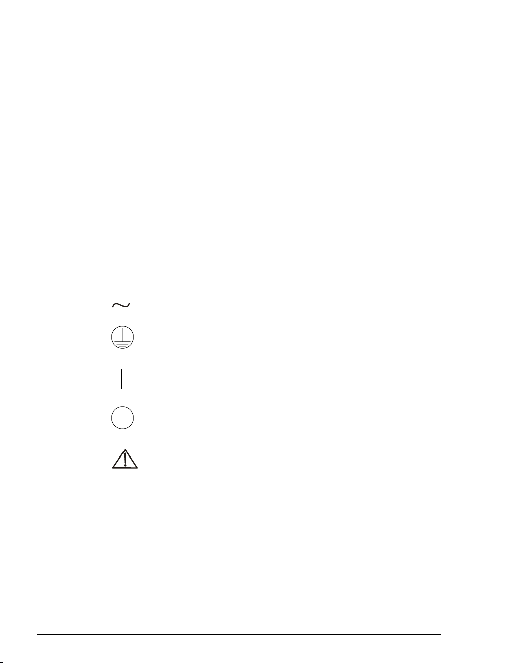
The symbols below appear on the AS or on AS labels.
Alternating current
Protective conductor terminal (earth ground)
Power supply is on
Power supply is off
Indicates a potential hazard. Refer to the operator’s manual for
an explanation of the hazard and how to proceed.
6 Doc. 065051-03 1/08
Page 19
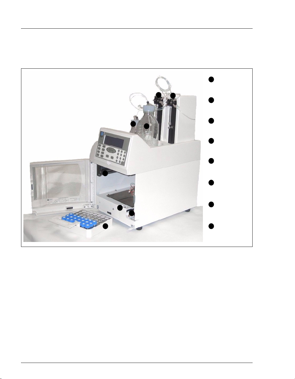
2.1 Overview of Features
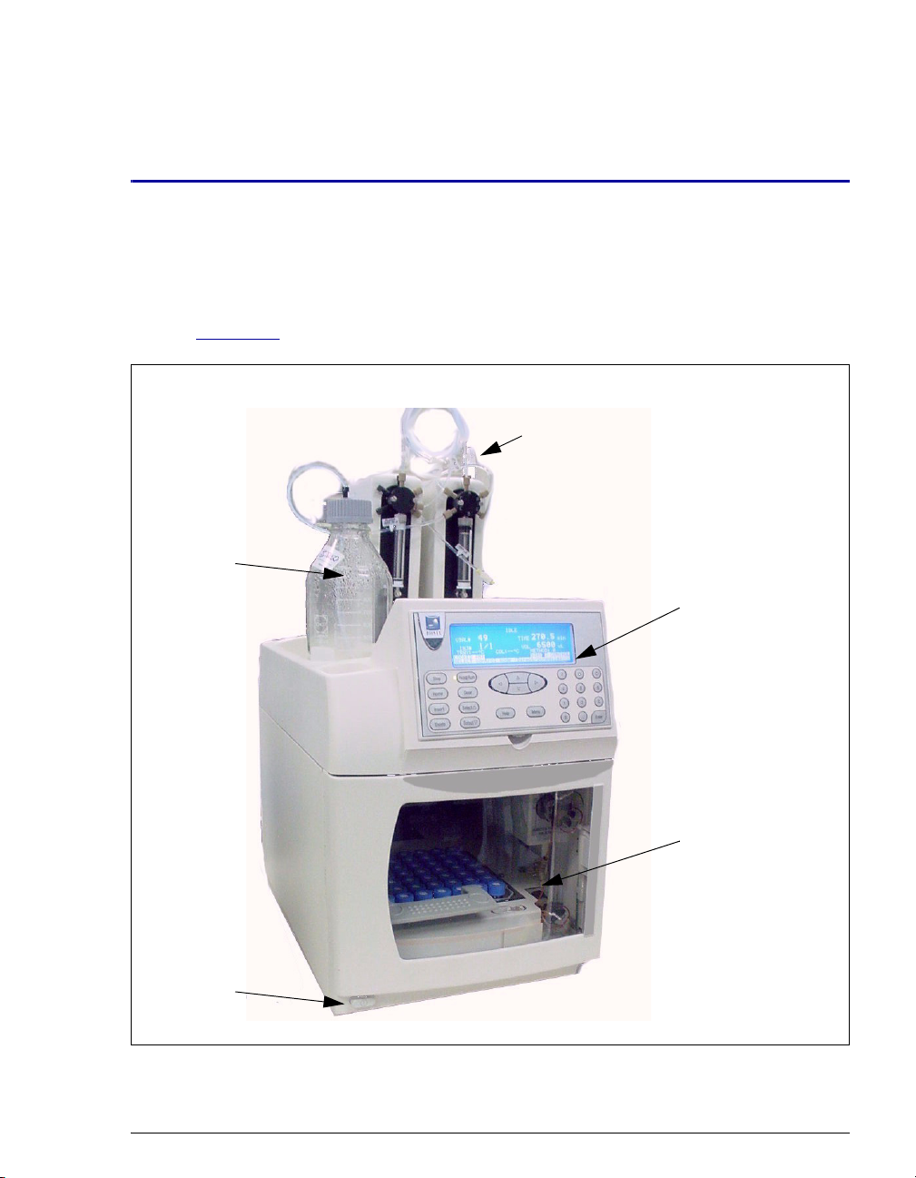
Figure 2-1 illustrates the main features of the AS Autosampler.
Flush
Reservoir
2 • Description
Sample and
Prep Syringes
Front
Panel
Autosampler
Compartment
Power
Switch
Figure 2-1. AS Operating Features
Doc. 065051-03 1/08 7
Page 20

AS Autosampler Operator’s Manual
Front Panel
The front panel contains a liquid crystal display (LCD) and membrane keypad
(see Section 2.2
Power Switch
The power switch is in the lower left corner of the AS. The switch functions only
when the door is fully closed.
Autosampler Compartment
The autosampler compartment contains a stationary sample tray and an XYZ
sampling needle arm that moves from vial to vial during operation (see
Section 2.3
port. Valves for sample injection or for diverting sample flow to different systems
can optionally be included.
Syringe and Reservoir Organizer
The organizer on top of the autosampler holds the sample syringe, the flush liquid
reservoir, and the optional prep syringe and reagent reservoirs. See Section 2.3.1
for details.
). The front panel permits manual control of AS functions.
). The compartment also contains an inject port, flush port, and waste
Options
• Sample Preparation: When this option is installed, the AS can perform
sample preparation functions such as diluting standards or dispensing
reagents. See Section 2.3.1
for details.
• Sample Temperature Control (not pictured): When this option is installed,
the AS provides uniform heating and cooling of the sample tray. See
Section 2.3.7
for details.
• Simultaneous Injection (not pictured): When this option is installed, the AS
can deliver sample to two independent ion chromatography (IC) systems
simultaneously. See Section 3.6.9
for details.
• Sequential Injection (not pictured): When this option is installed, the AS can
deliver sample to two independent ion chromatography (IC) systems
alternately.
• Concentrator Injection (not pictured): When this option is installed, the AS
can load sample to a Dionex ultra-low pressure concentrator column. See
Section 2.3.10 for details.
8 Doc. 065051-03 1/08
Page 21
Valve Options
One or two injection valves can be installed in the AS autosampler compartment.
Or, the AS can be configured without an injection valve and instead be connected
to one or two valves installed in other chromatography system modules. Two
injection valves are required for simultaneous injections.
For the sequential injection option, a diverter valve is installed in the AS.
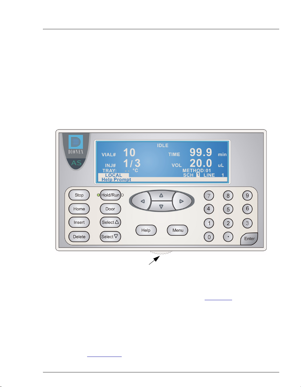
2.2 Front Panel Features
2 • Description
Adjust screen contrast
Figure 2-2. AS Front Panel
Information is displayed on the LCD, or screen. To adjust the screen contrast, use
the knurled knob in the recess below the keypad (see Figure 2-2
).
From the keypad, you can:
• Directly control AS operation
• Create and modify programmed series of operating steps, called methods
• Create and modify programmed series of injections, called schedules
Refer to Section 2.2.2
Doc. 065051-03 1/08 9
for a summary of how to select screens and edit parameters.
Page 22
AS Autosampler Operator’s Manual
(
)
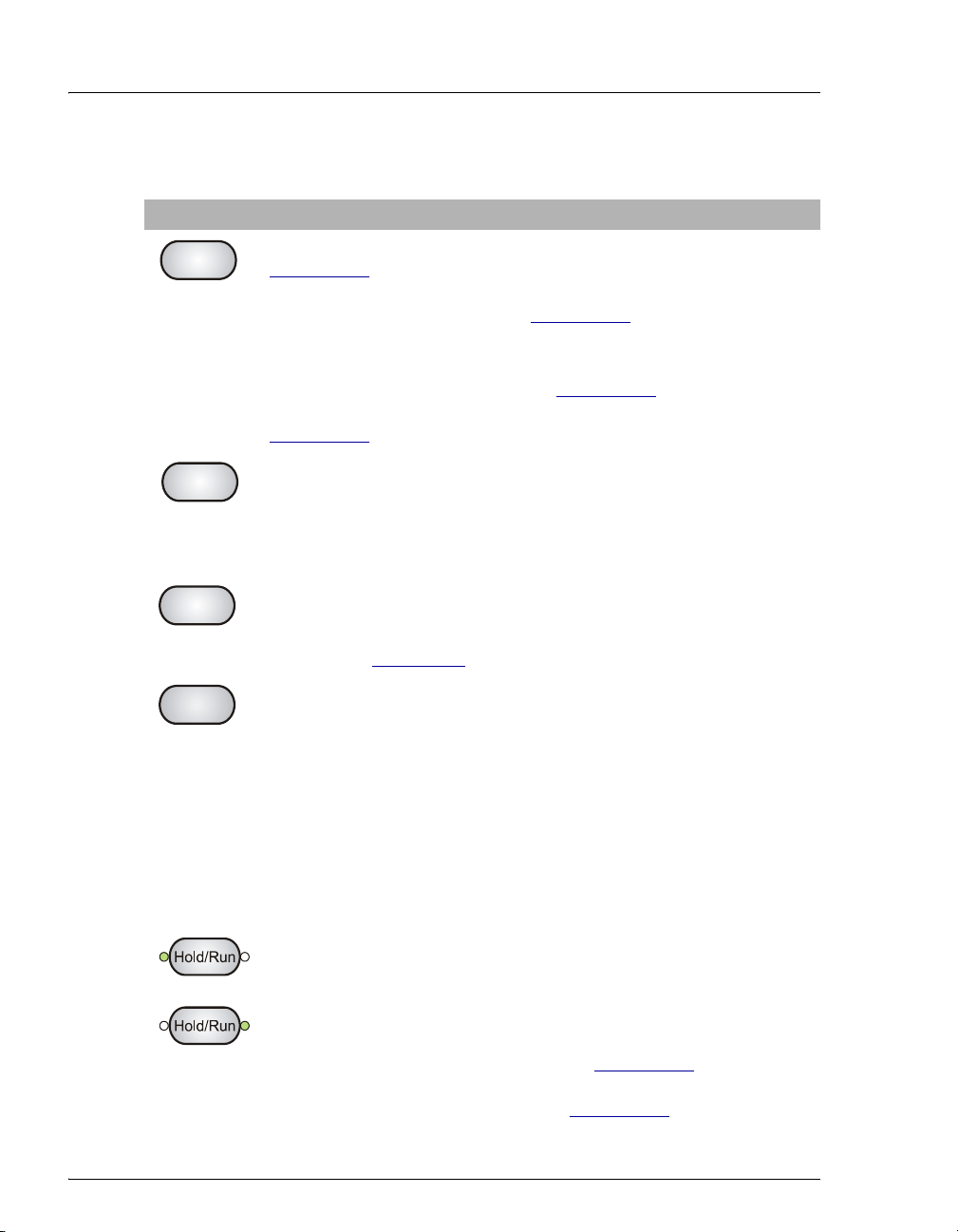
2.2.1 Keypad Button Functions
Button Function
Stop
Stops a schedule if the AS is in Local mode, Schedule control (see
Section 2.5.1
). A confirmation message appears; press Stop again to
abort the schedule or Hold/Run to resume.
If the AS is in Direct Control (see Section 2.5.1
the current syringe and/or sampling arm movement.
Note: Pressing Stop while the AS is in Direct Control, Locked
Remote mode (software control) (see Section 2.5.2
recommended. Use the controls on the software Control panel (see
Section 2.5.2
) to stop a sequence.
), pressing Stop stops
) is not
Home
Insert
Delete
(Hold)
Run
Sends the needle arm to its home position. This button functions only
when the AS is in Local mode. If a schedule is in progress, it must be
on hold. If you press Home when a schedule is on hold, and then
resume the schedule, the needle arm returns to the location it was in
when you pressed Home.
Inserts a new step into a method or schedule. Move the cursor to the
leftmost field on the
SAMPLE PREP, TIMED EVENTS, or SCHEDULE
screen and press Insert. The new step is added above the cursor
position. See Appendix D
for details about front panel operation.
Delete performs several functions:
• Cancels an entry that is in progress and restores the previous value.
• Returns a field to its default value (if an entry is not in progress).
• Deletes a line in a method or schedule. To do this, position the
cursor in the leftmost field of the line that you want to delete and
press Delete twice.
• Deletes an entire method or schedule. To do this, position the
cursor in the method or schedule edit field, or in the time field of
the
INIT step, and press Delete twice.
At power-up, the AS is on hold (the left LED is illuminated). After you
select a schedule to run, pressing Hold/Run starts the schedule (the
right LED is illuminated). When the schedule is complete, the AS
returns to hold. When running, press Hold/Run to pause the schedule.
This button functions only when the AS is in Local mode.
Note: If the wait operation is enabled (see Section 2.7.1
pauses when it reaches the wait step in the method. Press Hold/Run to
continue. You can disable the wait (see Section 2.7.4
), the AS
).
10 Doc. 065051-03 1/08
Page 23
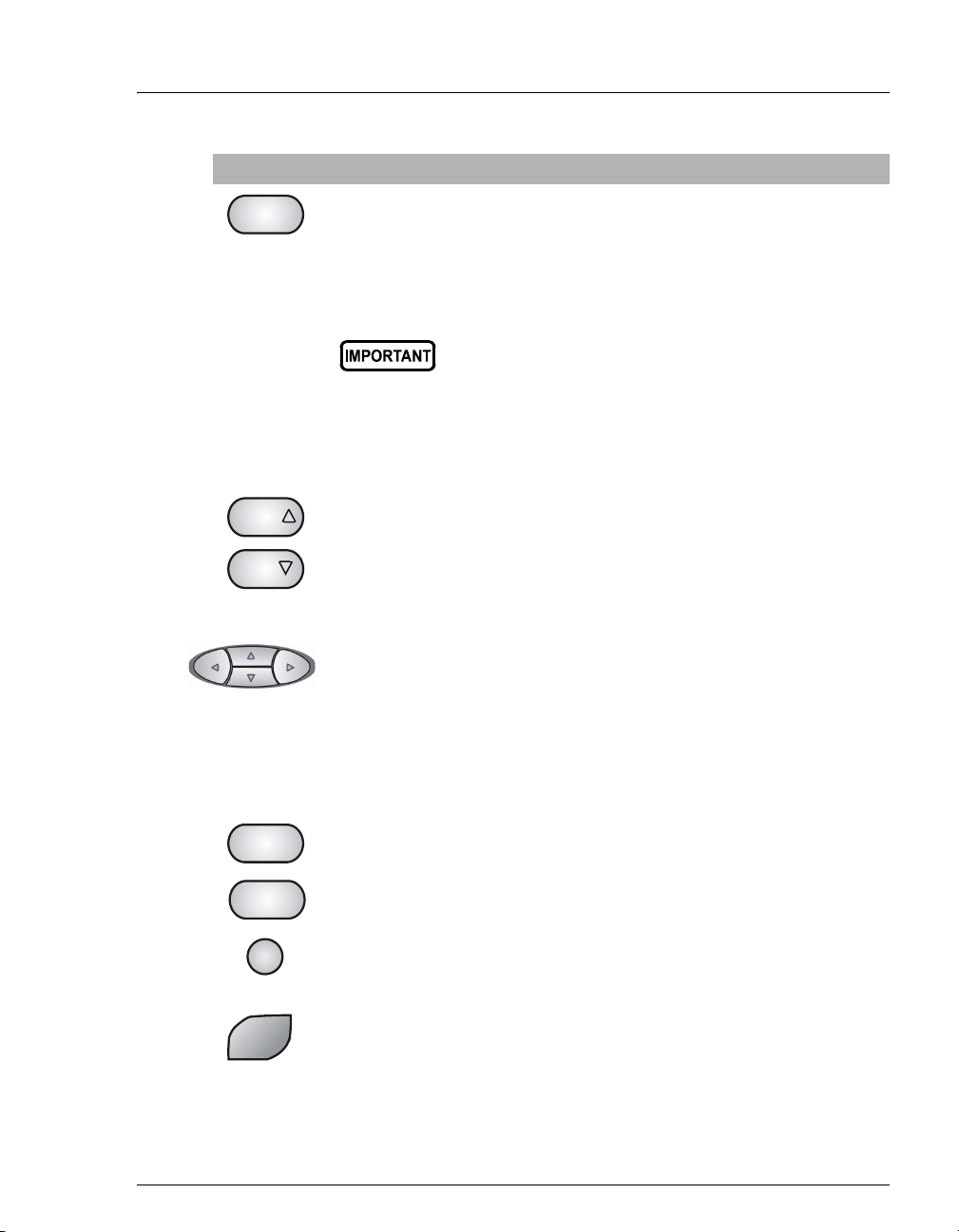
Button Function
If you press the Door button when a sequence (or front panel
Door
schedule) is running, a message screen indicates whether it is currently
safe to open the door. If it is, the screen displays for how much longer it
is safe to open the door. Opening the door without first pressing this
button, or when the message indicates it is not safe, ends the currently
running sequence (or schedule).
Select
The Select buttons scroll through predetermined options in entry
fields. To confirm the selected value, press Enter or move out of the
field by pressing a cursor arrow button. In fields that have
Select
predetermined numeric choices, Select Δ increases the value by one
unit and Select ∇ decreases the value by one. Holding down a Select
button increases (or decreases) the value continuously.
The arrow buttons move the cursor in the direction of the arrow to the
next entry field (if one exists). At the end of a line, the left arrow wraps
the cursor around to the next entry field on the line above; the right
arrow wraps the cursor to the next entry field on the line below. The up
and down arrows do not wrap around.
2 • Description
The autosampler door must remain closed during
operation. If the door is opened during operation,
the sampling arm stops immediately. If a sequence
(or schedule) is running, it is ended. If you want to
open the door during a sequence (or schedule),
first press the Door button, and then follow the onscreen instructions.
After entering a new value in an entry field, pressing an arrow button
saves and/or executes the change.
Displays a help screen specific to the current entry field.
Help
Displays a list of the available screens.
Menu
1
The numeric buttons enter the selected number into the current entry
field. On a menu, pressing a numeric button opens the corresponding
screen.
Enter
Doc. 065051-03 1/08 11
Saves and/or executes changes made in entry fields. If a menu screen is
displayed, pressing Enter opens the highlighted screen.
Page 24
AS Autosampler Operator’s Manual
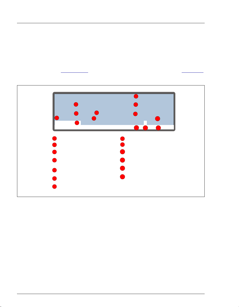
g
2.2.2 Display Screens
The LCD displays status information and allows access to all AS
operations.
When the power is turned on, the AS performs an initialization sequence
(see Section 3.1.1
is an example of the
) and then displays the MAIN STATUS screen. Figure 2-3
MAIN STATUS screen during AS operation.
1
8
9
VOL
8
9
20.013
METHOD: 01
SCH LINE
11
Time since last injection
Volume to be injected
Current method
Control mode
Current s chedule
Schedule line currently in
progress
10
1
121113
min
uL
8
INJ#
2
10 10.6
3
/
6
°C
↑
20
7
status
m ode
VIAL#
5
TRAY:
LOCAL
Help Prompt
Operating status
1
Current vial or well
2
3
Current injection
Total injections s cheduled
4
for this vial
Current tray temperature
5
Tray temperature
6
(increasing)
Operatin
7
LOADING LOOP
TIME
4
10
12
13
Figure 2-3. Main Status Screen
NOTE TRAY temperature is displayed only when the
sample temperature control option is installed.
12 Doc. 065051-03 1/08
Page 25

2 • Description
To access other AS screens:
Press the Menu button. The MENU of SCREENS appears (see Figure 2-4).
MENU of SCREENS
FLUSH/PRIME
MAIN STATUS
1
DETAIL STATUS
2
METHOD MENU
3
SCHEDULE
4
MODULE SETUP MENU
5
Help Prompt
Figure 2-4. Menu of Screens
To select a screen on the menu, use one of the following methods:
6
TIME FUNCTION IN
7
DIAGNOSTIC MENU
8
9
TIME FUNCTION OUT
• Press the keypad numeric button corresponding to the screen’s
number on the menu.
• Move the cursor to highlight the screen number and press Enter.
To display a brief description of each screen:
Press the Help button. See Appendix C for details about each screen.
To edit a field on the screen:
1. Press a cursor arrow button to position the cursor in the field to be
edited. Fields that are in reverse video (blue letters on white
background) can be edited. Other fields display information only.
2. If the field accepts numeric values, press the desired numeric buttons
to enter the value.
If the field has predetermined options, press the
Select Δ or Select ∇
button to choose the desired option.
3. To confirm the selected value, press
Enter or move the cursor out of
the field by pressing an arrow button.
Doc. 065051-03 1/08 13
Page 26
AS Autosampler Operator’s Manual
2.3 Autosampler Compartment
3
5
Prep Syringe
1
(Optional)
1
2
4
Sample
2
2
Syringe
Reagent
3
3
Reservoir
(Optional)
Flush
4
Reservoir
XYZ Sampling
5
Needle Arm
Flush, Waste,
6
and Inject Ports
6
7
8
Figure 2-5. Autosampler Compartment Features
Injection and/or
Diverter Valves
7
(Optional)
Sample Tray
8
(for Vials or
Well Plates)
14 Doc. 065051-03 1/08
Page 27

2.3.1 Syringe and Reservoir Organizer
The organizer on top of the autosampler holds the sample syringe, 1 L
flush reservoir, and the optional prep syringe and reagent reservoirs (see
Figure 2-5
Sample Syringe Functions
).
The sample syringe performs these operations:
• Pipettes liquid from one vial to another or to waste.
• Mixes a vial by repeatedly drawing and expelling the vial contents. If
AS is equipped with the sample preparation option, mixing is done
the
with the sample prep syringe instead of the sample syringe.
• Delivers sample to the injection valve.
The following sample syringe volumes are available:
2 • Description
Sample Syringe
Vol ume
100 μL 055064
250 μL (standard) 053916
500 μL 055065
1,000 μL 055066
5 mL* 053915
10 mL* 055068
*A 5 or 10 mL syringe is required for simultaneous
injections and optional for all other sampling modes. If a
5 or 10 mL syringe is installed, an 8.5 mL sampling
needle assembly (P/N 061267) is required.
Part Number
Doc. 065051-03 1/08 15
Page 28

AS Autosampler Operator’s Manual
Sample Preparation Option Functions
The AS can be equipped with a sample preparation option that includes a
sample prep syringe, a sample prep valve, and one 250 mL reagent
reservoir. Up to three additional reagent reservoirs can be configured.
The sample prep syringe performs these operations:
• Dispenses reagents from external reservoirs to any vial
• Mixes a vial by repeatedly drawing and expelling the vial contents
• Performs dilutions, allowing preparation of multilevel calibration
standards
• Performs liquid-liquid extractions by adjusting the height of the
needle in the vial
The following sample prep syringe volumes are available:
Prep Syringe Volume Part Number
250 μL 053916
500 μL 055065
1,000 μL 055066
2.5 mL 055067
5 mL (standard) 053915
10 mL 055068
The reagent reservoir connects to port A on the sample prep valve.
Additional reservoirs can be connected to ports B, C, and D. Commands
from the AS front panel screens or from Chromeleon or Chromeleon
Xpress let you select the reservoirs.
NOTE The 5 mL and 10 mL syringes are intended for most
sample prep functions. Use the smaller syringes only
for applications that require low flow rates.
NOTE The 2.5 mL syringe (P/N 055067) can only be used
with the sample preparation option. It cannot be
used as a sample syringe.
16 Doc. 065051-03 1/08
Page 29

2.3.2 Sampling Needle Arm
The autosampler door must remain closed during operation. If you
open the door during operation, the sampling arm stops immediately.
If a schedule is running, it is ended. To safely open the door during a
schedule, press the Door button. See Section 3.9 for details.
During operation, the sampling needle arm moves the sample needle
along X-, Y-, and Z-axes. The sample tray remains stationary throughout
the sampling process.
To sample from a vial or well plate, the arm moves to the specified
position in the tray and lowers the needle into the vial or well. The
sampling needle pierces the vial cap or well plate cover to allow fluid to
be drawn or delivered. When sampling is complete, the arm raises the
needle out of the vial or well. When running a schedule of injections, vials
or wells can be sampled in any order.
The needle height (the distance from the tip of the needle to the bottom of
the vial or well) can be adjusted, allowing operations such as liquid-liquid
extraction.You can set the needle height in a Chromeleon or Chromeleon
Xpress program (see Section 3.2.2
page 292
).
2 • Description
) or in a front panel program (see
NOTE Changing the needle height is not recommended
when sampling from a micro-well well plate,
because the well depth is shallow. You can adjust the
needle height in a deep-well well plate as required,
provided the needle remains submerged in sample.
This ensures accurate sample aspiration.
During a flush operation, the sampling needle arm delivers flush fluid to
the flush port (see Figure 2-7
Doc. 065051-03 1/08 17
).
Page 30
AS Autosampler Operator’s Manual
S
eedle
A
y
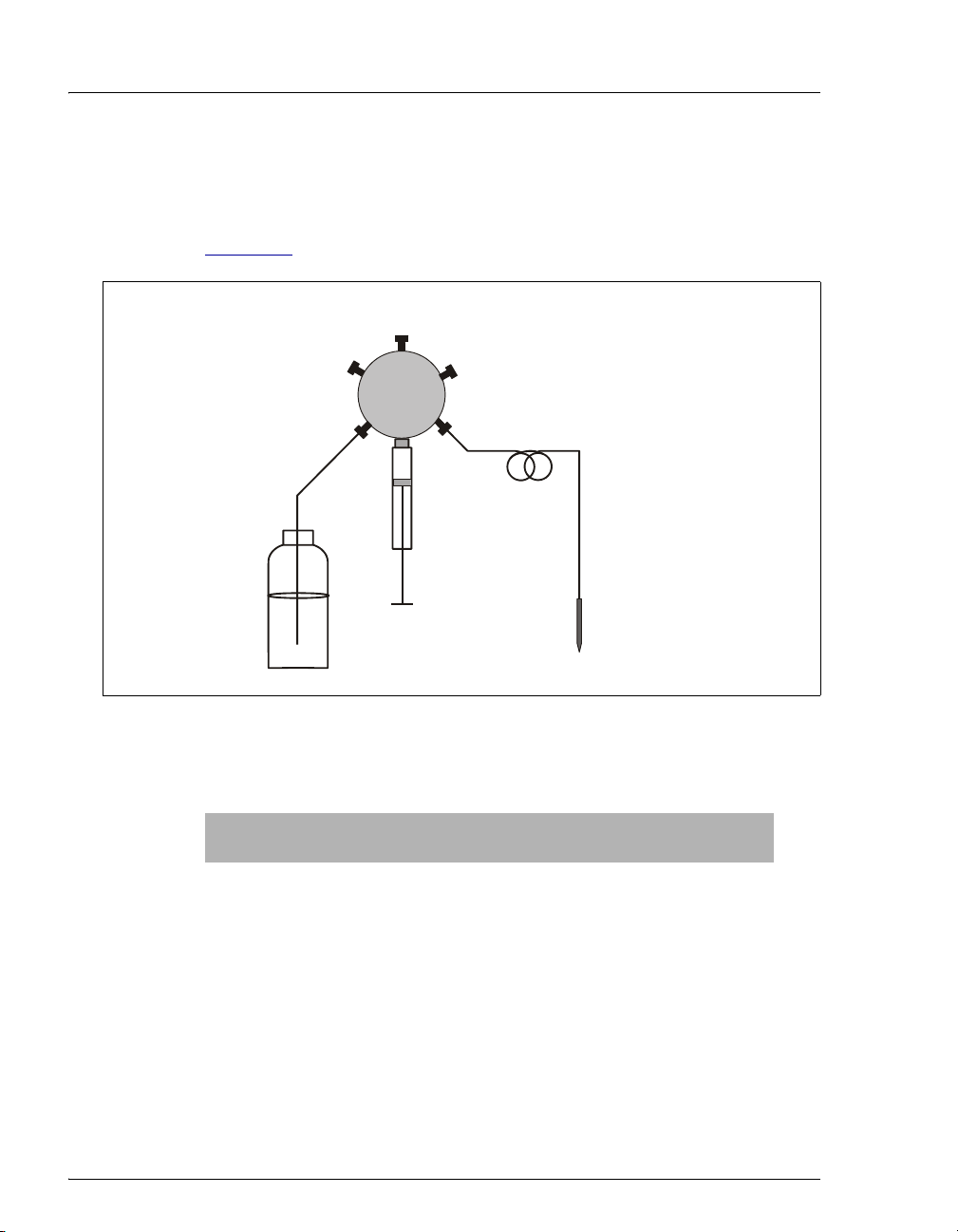
2.3.3 Sampling Needle Assembly
The sampling needle assembly consists of a PEEK™ sampling needle and
a line, which connects the sample syringe and the sampling needle (see
Figure 2-6
).
ample Syringe
Valve
A
F
E
D
Sample
Syringe
B
C
Sampling
Needle
ssembl
Flush Reservoir
Sampling
N
Figure 2-6. Sample Syringe with Sampling Needle Assembly
Two assemblies are available (see the table below).
Sampling Needle
Assembly
PEEK Needle with
1.2 mL line
PEEK Needle with
8.5 mL line
a
a. The 8.5 mL sampling needle assembly is standard when the AS is
configured with the simultaneous injection option.
18 Doc. 065051-03 1/08
Used With Part Number
Sample syringe volumes
054271
1mL or less
Sample syringe volumes
061267
greater than 1 mL
Page 31

2.3.4 Flush, Waste, and Inject Ports
The flush port flushes the outside of the sampling needle with fluid from
the flush reservoir. Excess fluid flows to the waste port. The waste port
accepts waste fluid from the sampling needle and the flush port, and
directs it out the drain line. The inject port (see Figure 2-7
sample from the sampling needle and delivers it to the injection valve.
Waste Port
Flush Port
Figure 2-7. Flush, Waste, and Inject Ports
2.3.5 Sample Vials and Well Plates
2 • Description
) accepts the
Inject Port
Vial Trays and Vials
The following vial trays are available. See the following section for well
plate information.
Tray Material Vial Size Held Tray Capacity Part Number
Plastic 10 mL 49 062374
Aluminum 0.3 mL, 1.5 mL 100 062481
a
Insulated Aluminum
a. Required for the sample temperature control option. Includes tray
covers for empty tray rows.
0.3 mL, 1.5 mL 100 062377
The following vials are available:
Vial Size and Material Quantity Part Number
0.3 mL polymer Package of 100 055428
1.5 mL glass Package of 100 055427
10 mL PolyVial™ Package of 100 055058
1.5 mL plastic Package of 100 061696
Doc. 065051-03 1/08 19
Page 32

AS Autosampler Operator’s Manual
Dionex does not recommend using the 10 mL plastic tray with the
sample temperature control option because the plastic tray is
inefficient at heating and cooling the vials. In addition, the tray is not
designed for temperatures above 40 °C (104 °F) and may deform at
temperatures above 40
Well Plates and Trays
°C.
Dionex recommends using well plates in the AS if you have limited
amounts of sample or if you require more than 100 sample positions.
Follow these guidelines when using well plates:
• 2 mL deep-well plates are suitable for ion chromatography (IC)
applications, where concentration of ions is above 1 ppm.
• 0.5 mL and 0.45 mL micro-well plates are not recommended for IC
applications.
• Where concentration of ions is below 1 ppm, Dionex recommends
using 10 mL PolyVials (P/N 055058, package of 100).
The following well plate tray packages are available:
Well Plate Tray Type Includes Part Number
Micro-well plate tray One micro-well plate tray, two micro-well
plates with 0.5 mL round (U-shaped) wells, and
two covers (not suitable for IC applications)
Deep-well plate tray One deep-well plate tray, two deep-well plates
with 2 mL wells, and two covers (suitable for
IC applications, where concentration of ions is
above 1 ppm)
066324
066325
Additional well plates and covers can be ordered separately. See
Appendix F
Well Plate Tray Notes
for reordering information.
• All well plate trays can be used with the sample temperature control
option.
• Each well plate tray also holds ten, 1.5 mL vials.
• The micro-well plate tray can hold either type of micro-well plate (V-
shaped wells or U-shaped wells).
20 Doc. 065051-03 1/08
Page 33

• The AS automatically detects the type of tray installed.
n
2.3.6 Injection Valve Options
The AS can optionally have one or two injection valves installed inside
the autosampler compartment. The injection valves are six-port,
electrically-activated Rheodyne valves. The valves have two operating
positions: Load and Inject (see Figure 2-8
2 • Description
).
Concentrator
Column
(optional—
replaces loop)
Sample In
Sample
Loop
To Wa st e
LOAD POSITION
(5)
S
(6)
W
(1)
L
L
(4)
C
(3)
P
(2)
From Pump
Sample In
To Co l u m n
Sample
Loop
(6)
To Wa st e
INJECT POSITION
(5)
W
(1)
S
L
L
From Pump
(4)
C
P
(2)
To C o l u m
(3)
Figure 2-8. Injection Valve Flow Schematics
Eluent flows through either the Load or Inject path, depending on the valve
position:
• In the Load position, sample flows from the AS inject port line, through the
valve, and into the sample loop, where it is held until injection. Eluent flows
from the pump, through the valve, and to the column, bypassing the sample
loop. Excess sample flows out to waste.
• In the Inject position, sample is swept to the column for analysis. Eluent flows
from the pump, through the sample loop, and on to the column, carrying the
contents of the sample loop with it.
Doc. 065051-03 1/08 21
Page 34

AS Autosampler Operator’s Manual
2.3.7 Sample Temperature Control Option
The sample temperature control option provides heating and cooling of
the sample tray. You can program the temperature set point from 4
60
°C. Samples in the tray are uniformly heated or cooled to the
programmed set point (to a minimum of 20
maximum of 40
The sample temperature control option sits on the workbench below the
autosampler compartment (see Figure 2-9
°C above ambient). The absolute range is 4 °C to 60 °C.
°C to
°C below ambient and a
).
Sample
Temperature
Control Option
Figure 2-9. AS with Sample Temperature Control Option
NOTE The temperature inside the autosampler compartment
may exceed ambient by up to 2 °C. The sample
temperature control option is recommended for samples
that are temperature sensitive.
22 Doc. 065051-03 1/08
Page 35

2.3.8 Simultaneous Injection Option
When the AS simultaneous injection option is installed, a single AS can
deliver sample to two independent chromatography systems. The sample
is injected simultaneously to both systems (two injection valves are
required). Dual analyses can be performed with only one sample, thus
increasing sample throughput and eliminating the need to label, fill, and
track two sample vials.
In Chromeleon or Chromeleon Xpress, the two chromatography systems
and the AS are configured into a single timebase and each system is
assigned a unique device name and channel. This lets you monitor and
control both systems from one Control panel and run all samples in one
sequence.
2 • Description
The simultaneous injection option requires a 5 or 10 mL
and an 8.5 mL sampling needle assembly (see Section 2.3.3
injections are required with this option.
See Section 3.6.9
for details about simultaneous injections.
2.3.9 Sequential Injection Option
When the simultaneous option is installed, a single AS can deliver sample
to two independent chromatography systems. With the sequential option,
sample is delivered to the first system, flow is rerouted (diverted), and
sample is then delivered to the second system. Sequential injection allows
different samples to be injected into each system.
The sequential injection option requires two injection valves and a
diverter valve (for switching sample flow between the two systems). The
diverter valve is installed in the AS autosampler compartment. The
injection valves must be installed in the IC system’s chromatography
compartment.
See Section 3.6.11
NOTE The diverter valve can only be controlled by
for details about sequential injections.
Chromeleon or Chromeleon Xpress. It is not
controllable from the AS front panel.
sample syringe
). Full-loop
Doc. 065051-03 1/08 23
Page 36

AS Autosampler Operator’s Manual
2.3.10 Concentrator Injection Option
The AS concentrator injection option lets an AS deliver sample and
reagent to a Dionex ultra-low pressure concentrator column. With this
option, a concentrator column is installed on the injection valve instead of
a sample loop. A 5 or 10 mL
larger sample loading volumes. If the 5 or 10 mL
installed, an 8.5 mL sampling needle assembly must also be installed (see
Section 2.3.3
The AS is capable of delivering at a maximum pressure of 690 kPa
(100 psi). When setting up concentrator injections, make sure to select
syringe speeds that will keep the backpressure below 690 kPa (100 psi),
taking into account the pressure from the installed tubing and the
concentrator column. A syringe speed of 1 or 2 is required. See
Section 3.8
).
for details.
sample syringe can be installed to allow
sample syringe is
See Section 3.6.10
for details about concentrator injections.
24 Doc. 065051-03 1/08
Page 37

2.4 Rear Panel Features
1 2 3
2 • Description
USB
1
Receptacle
TTL/Relay
2
Connectors
Syringe
3
Connectors
Auxiliary
4
Power
Connector
4
5
Main Power
5
Receptacle and
Fuse Holder
Figure 2-10. AS Rear Panel
2.4.1 USB Receptacle
The USB receptacle provides a connection to the Chromeleon or
Chromeleon Xpress computer. To enable computer control of the
autosampler, connect a USB cable between the USB receptacle on the AS
rear panel and a USB port on the computer or USB hub. See Section B.3.8
for USB connection instructions.
Doc. 065051-03 1/08 25
Page 38
AS Autosampler Operator’s Manual
2.4.2 TTL/Relay Connectors
The eight TTL and relay connectors interface with Dionex and nonDionex modules. The input connectors allow for relay and TTL control of
the autosampler by a connected module(s). The output connectors allow
the AS to control other module(s). Appendix E
TTL functions and the connections between the AS and other modules.
2.4.3 Fuse Holder and Power Receptacle
The fuse holder contains two 3.15 amp fast-blow fuses (P/N 954745). For
instructions on how to change the fuses, see Section 5.18
The power cord plugs into the IEC 320 three-prong receptacle.
The power supply cord is used as the main disconnect device. Make
sure the socket-outlet is located near the AS and is easily accessible.
Le cordon d'alimentation principal est utilisé comme dispositif
principal de débranchement. Veillez à ce que la prise de base soit
située/installée près du module et facilement accessible.
Das Netzkabel ist das wichtigste Mittel zur Stromunterbrechung.
Stellen Sie sicher, daß sich die Steckdose nahe am Gerät befindet und
leicht zugänglich ist.
describes the relay and
.
26 Doc. 065051-03 1/08
Page 39

2.5 Autosampler Control
The AS can be controlled locally, from the front panel keypad and display (see
Section 2.5.1
Chromeleon Xpress software is installed (see Section 2.5.2
from an integrator or other remote controller can also be used to control the AS.
See Appendix E
2.5.1 Local Control
), or remotely, with a personal computer on which Chromeleon or
for details about TTL control.
In Local mode, the AS receives commands from the front panel buttons
and screens. When the AS is powered up, it is always in Local mode.
When the AS is in Local mode, two types of control are available: Direct
and Schedule.
• In Direct control, you enter control commands and parameters on the
AS screens, and the AS executes the commands immediately.
• In Schedule control, you define a list of injections (a schedule) to be
run in sequence. The schedule can be defined, saved, and then run at a
later time.
2 • Description
). TTL input signals
The table below summarizes the AS Local control configurations:
Operating/Control Mode Autosampler Operation
Local/Direct Control Commands are entered from the AS front panel
and executed immediately after being entered.
Local/Schedule Control Commands are entered from the AS front panel
and executed by running a schedule programmed
from the front panel.
Local/Direct Control Mode
You can directly control the following AS functions from the front panel:
• TTL and relay outputs
• Injection valve position
• Second injection valve position or diverter valve (if installed)
• Tray set point (if installed)
Doc. 065051-03 1/08 27
Page 40

AS Autosampler Operator’s Manual
Set these functions from the DETAIL STATUS screen (see Figure 2-11).
DETAIL
VIAL#:
INJ#:
METHOD:
TRAY:
LOCAL
Help Prompt
Local/Schedule Control Mode
20 °C25
Figure 2-11. Detail Status Screen Example
IDLE
TIME:
VOL:
TRAY:
LOOP:
NORMAL FULL
DIRECT CONTROL
100
min
uL
2mL
uL
TTL1
TTL2
RLY1
RLY2
INJ VLV L
The AS runs all injections according to a programmed schedule. The
schedule defines a series of vials to be sampled and the operating
parameters to run on each vial. A schedule consists of the following
parameters:
• The vials to sample
• The number of injections to draw from each vial
• The volume of each injection
• The method to run on each injection
• The action to take when a scheduled vial is missing
1
0
0
0
You program, save, and edit schedules from the
Figure 2-12
). The AS can store up to nine schedules in memory. The
SCHEDULE screen (see
stored schedules are retained in memory when the AS is turned off.
Section D.6
MISSING VIAL ACTION:
LINE ENDSTART
1
Help Prompt
28 Doc. 065051-03 1/08
describes how to create schedules.
EDIT
VIAL#
-
-
Figure 2-12. Schedule Screen
SAVE TO
STOP
INJ/ INJ
VIAL METHODVOL(uL)
1
RUNSCHEDULE
25.0 111
Page 41

2 • Description
Each injection in a schedule is assigned a method (a series of operating
instructions that tells the AS how to perform a single injection). A method
consists of the following three phases:
Method Phase Used To Examples
Sample prep Prepare the sample for injection Pipetting, mixing, diluting
Method setup Set parameters that remain
constant throughout the method
Timed events Perform functions at a specific
time in the method
When the method runs, the
AS performs the sample prep steps first,
followed by the method setup, and then the timed events steps.
Section D.5
Notes
describes how to create methods.
• See Appendix D for details about front panel operation.
• Some autosampler operations are not available from the AS front
panel and can only be accessed from Chromeleon or Chromeleon
Xpress. These include setting different aspirate and dispense syringe
speeds and sampling from well plates.
Sample needle height, sample
temperature
Loading the sample loop,
injecting
Doc. 065051-03 1/08 29
Page 42

AS Autosampler Operator’s Manual
2.5.2 Computer Control (Locked Remote Mode)
In Locked Remote mode, Chromeleon or Chromeleon Xpress software
sends commands from the host computer via the USB interface.
Connecting the AS to a Control panel (see Figure 2-13
selects the Locked Remote mode. In this mode, you cannot change any
operating parameters from the front panel keyboard. To return the AS to
Local mode, clear the Connect check box on the AS Control panel.
) immediately
Figure 2-13. Example AS Control Panel
There are two modes for controlling the AS using Chromeleon or
Chromeleon Xpress:
• In Direct mode, you select operating parameters and commands
directly from the Control panel. The AS executes the commands
immediately.
30 Doc. 065051-03 1/08
Page 43

2 • Description
• In Automatic mode, you create a list of samples (a sequence) to be
processed automatically. The sequence defines a series of vials to be
sampled and the AS operating parameters to run on each vial. The
sequence is similar to a front panel schedule (see Section 2.5.1
For instructions on how to connect the AS to Chromeleon or Chromeleon
Xpress, see Section 3.2.1
autosampler using Chromeleon or Chromeleon Xpress, see Section 3.2.2
For detailed instructions, refer to the Chromeleon Help or Chromeleon
Xpress.
. For an overview of how to operate the
2.6 System Wellness and Predictive Performance
The Chromeleon System Wellness panels provide easy access to the
autosampler’s built-in diagnostic and calibration features. You can use the
Wellness panels to perform the following tasks:
• Calibrate the inject port tubing volume
• Align the sampling needle in the inject port
),
.
• Calibrate and test the leak sensor
• Monitor usage of replaceable parts (see the description of Predictive
Performance below)
Wellness panels for calibrating the inject port tubing, aligning the sampling
needle, and monitoring usage of parts are available on the Control panel (see
Figure 2-13
sensor (see Section 5.11
The Chromeleon Predictive Performance feature provides functions for
monitoring the lifetime of replaceable parts and for planning and recording
service procedures. You can use the Chromeleon Predictive Performance feature
to perform the following tasks:
). A separate panel is available for calibrating and testing the leak
).
NOTE You can also perform System Wellness tasks from the
front panel screens. See Appendix D
for details.
• Monitor how many times a part has been used since it was last replaced.
Chromeleon monitors usage of the following AS parts: injection valve,
diverter valve, XYZ sampling needle arm, sampling needle assembly, needle
seal assembly, sample syringe, and prep syringe.
Doc. 065051-03 1/08 31
Page 44

AS Autosampler Operator’s Manual
• Display a warning message in the Chromeleon Audit Trail when a monitored
part is approaching its usage limit and when the limit is reached.
• Set the usage limits for monitored parts to suit your needs.
• Record when a part is serviced and reset the usage counter.
All Predictive Performance commands and parameters are available in the
Chromeleon Commands dialog box (press the F8 key or select Command on the
Control menu to open the Commands dialog box).
You can view and reset the usage counters for the various replaceable parts on
either the AS Wellness panel (see Figure 2-14
Section C.9.6
above, are available only in Chromeleon.
). The remaining Predictive Performance functions, described
) or the USAGE LOG SCREEN (see
Figure 2-14. Example AS Wellness Panel
(Default Warning Values for All Parameters Shown)
32 Doc. 065051-03 1/08
Page 45

2.7 Theory of Operation
2.7.1 Understanding the Wait Operation
NOTE This section pertains to AS operation in
Local/Schedule Control mode (see Section 2.5.1
only.
The wait operation is a step in the sample prep phase of a method. After
performing all other sample prep steps, the AS waits for a continue
command before performing the method’s timed events. The continue
command can be sent via the front panel
signal.
The wait’s position in the sample prep steps determines whether samples
are overlapped or run sequentially:
• When the wait operation is the last step in the sample prep phase (the
default), samples are overlapped (see Section 2.7.2
• When the wait operation is at the beginning of the sample prep phase,
samples are run sequentially (see Section 2.7.3
2 • Description
)
Hold/Run button or a TTL input
).
).
NOTE The wait operation can be disabled (see
Section 2.7.4
Doc. 065051-03 1/08 33
).
Page 46

AS Autosampler Operator’s Manual
US
2.7.2 Overlapping Sample Preparation
When the wait operation is at the end of the sample prep phase (the
default), the
collection is occurring for one injection, the AS performs the sample prep
steps for the next injection (see Figure 2-15
the schedule run flow of operations, see Section 2.7.6
AS overlaps sample preparation. This means that while data
). For a detailed description of
.
Start First Method
SAMPLE PREPWASH /
FLUSH
NOTE:
The WAIT is ignored for
the first injection in a
Schedule.
Sample Overlap with Chromeleon or Chromeleon Xpress
If Chromeleon or Chromeleon Xpress is controlling the AS, front panel
settings for the wait operation are ignored. Instead, the Sample Overlap
option determines whether sample preparation is overlapped. Sample
overlap, which is selected in the Chromeleon Server Configuration
program, is enabled by default. For instructions on how to configure the
AS in Chromeleon, see Section B.3.12
Injection 1
SETUP TIMED EVENTSINIT
0.0
Overlap
Start Next Method
WAS H/
SAMPLE PREP SETUP TIMED EVENTSINIT
FLUSH
Wait for Continue
Command
WAI T
CONTINUE
Injection 2
0.0
Overlap
Start Next Method
WASH /
SAMPLE PREP
FL
H
Figure 2-15. Sample Prep Overlap: Wait Operation at
End of Sample Prep Phase (Default)
.
WAI T
34 Doc. 065051-03 1/08
Page 47

2.7.3 Running Samples Without Overlap
Placing the wait operation at the start of the sample prep steps allows
samples to be run sequentially. The
timed events for an injection before starting the next injection (see
Figure 2-16
).
AS completes the sample prep and
2 • Description
Start First Method Start Next Method
Run
FLUSH
SAMPLE PREPWAS H/
SETUP
TIMED EVENTS
INIT
Injection 1
Injection 2
WASH /
FLUSH
Continue Continue
WAIT
SAMPLE PREP
SETUP
TIMED EVENTS
INIT
Figure 2-16. No Sample Prep Overlap: Wait Operation at
Beginning of Sample Prep Phase
2.7.4 Operating the AS as the System Master (Disabling the Wait Operation)
When the wait operation is disabled, a single run command (for example,
pressing the
performs the schedule lines without requiring additional commands. This
allows the
sending TTL signals to start the pump and detector methods).
To disable the wait operation, press
SETUP MENU and press 5 to go to the SYSTEM PARAMETERS screen. Set
WAIT field to DISABLED (see Figure 2-17).
the
METHOD SYRINGE SPEED:
CUT SEGMENT VOLUME:
FLUSH SYRINGE SPEED:
Help Prompt
Hold/Run button) starts the schedule. Thereafter, the AS
AS to act as the system master (the AS controls the system by
Menu and 5 to go to the MODULE
SYSTEM PARAMETERS
WAIT:
DISABLED
4
SAMPLE MODE:
INJECT PORT VOLUME:
10
43
uL
NORMAL
uL
4
WASH /
FLUSH
Figure 2-17. System Parameters Screen
For details about the order of events during a schedule when the wait
operation is disabled, see Figure 2-20
Doc. 065051-03 1/08 35
.
Page 48

AS Autosampler Operator’s Manual
0.0
2.7.5 Understanding the Cycle Time
Cycle time is an optional feature that can be used to control the time
between injections. When a method is assigned a cycle time, the AS
delays sample injection until the specified time has elapsed since the
previous injection. Cycle time is measured from the start of the previous
method's timed events (see Figure 2-18
time zero for each method (the default), specifying a cycle time allows a
consistent time interval between injections, regardless of differences in
sample prep and timed events among methods.
). Assuming injection occurs at
WASH /
FLUSH
SAMPLE PREP
SETUP TIMED EVENTSINIT
Injection 1Start First Method
0.0
Start Next Method
WAS H/
SAMPLE PREP SETUP
FLUSH
Cycle Time
Wait fo r end
of cycle time
INIT
Injection 2
TIMED EVENTS
0.0
Start Next Method
WASH /
FLUSH
Cycle Time
SAMPLE PREP SETUP INIT
Figure 2-18. Cycle Time Example
A cycle's duration is never shorter than the specified time. However, cycle
time will be ignored, thus delaying injection, if any of the following
events occurs:
• WAIT FOR TEMP STABLE is enabled in the METHOD SETUP screen
(see Section C.6
the cycle time.
) and the temperature did not stabilize by the end of
• The sample prep wait operation is enabled and a run command did
not occur by the end of the cycle time.
• The previous method’s timed events extend beyond the cycle time.
If the cycle time expires before the injection occurs, a warning message is
displayed and the message is logged on the
Section C.9.6
36 Doc. 065051-03 1/08
).
MESSAGE LOG screen (see
Page 49

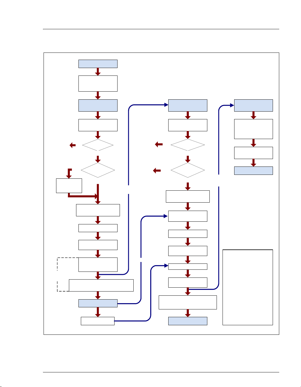
2.7.6 Operating Events During a Schedule
• Figure 2-19 shows the order of events during a schedule when the
wait operation is enabled.
• Figure 2-20 shows the order of events during a schedule when the
wait operation is disabled.
2 • Description
See Section 2.7.1
for details about the wait operation.
Doc. 065051-03 1/08 37
Page 50

AS Autosampler Operator’s Manual
Schedule Started
Preparing to Run:
Flush Inject Port and
Wash Needle
See Note #1
Wait for
Temperature
to Stabilize
See Note #2
Timed
Events
See Note #4
Method Starts for
Injection #1
Flush Inject Port and
Wash Needle
Vial Present?
No
Yes
Yes
Set
Temperature(s)
?
No
Do Sample Prep
(Pipetting, Mixing, etc.)
Method Setup
Execute INIT Step
Load Loop
Method Time 0.0
Inject
Start Cycle Timing
Method Times x.x to x.x
Set TTLs/Relays, etc.
Method Finished
See Note #3
End of Cycle Time
See Note #1
Sample Prep
Overlap
Continue
See Note #2
Method Starts for
Injection #2
Flush Inject Port and
Wash Needle
No
Vial Present?
No
Yes
Yes
Set
Temperature(s)
?
No
Do Sample Prep
(Pipetting, Mixing, etc.)
Wait for Previous
Method to Finish
Wait for Continue
Command
Method Setup
Execute INIT Step
Load Loop
Wait for Cycle Time
Method Time 0.0
Inject
Method Times x.x to x.x
Set TTLs/Relays, etc.
Method Finished
Sample Prep
Overlap
Method Starts for
Injection #3
Continue as Shown
for Method #2 Until
Last Scheduled
Injection Completed
Flush Inject Port and
Wash Needle
Schedule Ends
Notes:
1. The schedule either
stops and waits or skips to
the next vial, depending on
the action selected in the
schedule.
2. If multiple injections
from the same vial are
specified in the schedule,
the sample prep steps are
perfomed once only
(before the first injection).
3. The continue command
can be sent via the front
panel Hold/Run button or a
TTL input signal.
4. Use of cycle time is
optional.
Figure 2-19. Order of Events During a Schedule Run (Wait Enabled)
38 Doc. 065051-03 1/08
Page 51
Schedule Started
Preparing to Run:
Flush Inject Port
and Wash Needle
2 • Description
See Note #1
Wait for
Temperature
to Stabilize
See Note #2
Timed
Events
Method Starts for
Injection #1
Flush Inject Port and
Wash Needle
Vial Present?
No
Yes
Yes
Set
Temperature(s)
?
No
Do Sample Prep
(Pipetting, Mixing, etc.)
Set Up Method
Execute INIT Step
Load Loop
Method Time 0.0
Inject
Start Cycle Timing
Method Times x.x to x.x
Set TTLs/Relays, etc.
Method Finished
End of Cycle TimeSee Note #3
See Note #1
Sample Prep
Overlap
See Note #2
Yes
Method Starts for
Injection #2
Flush Inject Port and
Wash Needle
No
Vial Present?
No
Yes
Yes
Set
Temperature(s)
?
No
Do Sample Prep
(Pipetting, Mixing, etc.)
Wait for Previous
Method to Finish
Setup Method
Execute INIT Step
Load Loop
Wait for Cycle Time
Method Time 0.0
Inject
Method Times x.x to x.x
Set TTLs/Relays, etc.
Method Finished
Sample Prep
Overlap
Method Starts for
Injection #3
Continue as Shown
for Method #2 Until
Last Scheduled
Injection Completed
Flush Inject Port and
Wash Needle
Schedule Ends
Notes:
1. The schedule either
stops and waits or skips to
the next vial, depending on
the action selected in the
schedule.
2. If multiple injections
from the same vial are
specified in the schecule,
the sample prep steps are
perfomed once only
(before the first injection).
3. Use of cycle time is
optional.
Figure 2-20. Order of Events During a Schedule Run (Wait Disabled)
Doc. 065051-03 1/08 39
Page 52

AS Autosampler Operator’s Manual
2.7.7 Understanding the Status Display During a Run
During runs, the MAIN STATUS and DETAIL STATUS screens display the
operations currently being performed. Because of sample prep overlap,
information on multiple injections may be displayed simultaneously at
certain points in the schedule. For example, in Figure 2-21
injecting the sample and performing the timed events for the first
injection from vial 1 while preparing for the second injection.
, the AS is
Method Timed Events
Clock for Injection #1
DETAIL
VIAL#:
INJ#:
METHOD: TRAY:
TRAY:
LOCAL
Help Prompt
1
1/3
12.53
12mL
20 °C
25
Figure 2-21. Detail Status Screen Example
Preparing for
Injection #2
FLUSHING
TIME:
VOL:
LOOP:
NORMAL PARTIAL
SCH 1
12.5
25
100
LINE 10
Elapsed Time
Since Injection #1
min
uL
uL
INJ VLV
TTL1
TTL2
RLY1
RLY2
0
1
0
0
L
Notes
• The INJ# field is updated when the AS loads the loop for the next
injection.
• The TIME field and the METHOD timed events clock are reset to zero at
injection.
• The TIME field counts up from the injection until the next injection
occurs.
• The METHOD timed events clock counts up until all timed events have
been performed for an injection. The clock then stops and is no longer
displayed.
40 Doc. 065051-03 1/08
Page 53

2 • Description
2.7.8 Operating Events During Flushing and Priming
The AS automatically flushes the inject port and washes the outside of the
needle at the following times:
• At the beginning and end of a Chromeleon or Chromeleon Xpress
sequence or a front panel schedule
• Before each injection, while the schedule or sequence is running
Flushing can also be initiated manually when the AS is idle, or as a step in
the sample prep phase of a Chromeleon or Chromeleon Xpress program
or front panel method.
Manual priming of the flush and reagent lines must be initiated after
refilling a reservoir, or after the AS has been idle for a period of time. See
Section B.3.13
Flushing
The AS performs the following operations during flushing:
for instructions on priming the liquid lines.
• The sampling needle arm moves to the waste port and expels any
fluid from the needle.
• The sampling needle arm moves to the inject port and delivers a
volume of fluid for flushing the inject port.
• The sampling needle arm moves to the flush port and delivers a
volume of flush fluid. This washes the outside of the needle.
The flush reservoir and sample syringe are always used to perform the
flush.
The needle is washed with a factory-set volume. Select the volume of
liquid for flushing or priming on the Chromeleon or Chromeleon Xpress
Control panel (see Figure 2-13
Section C.7
syringe volume, the
volume is reached.
If you are using Chromeleon or Chromeleon Xpress to control the
autosampler, you can specify separate syringe speeds for aspirating and
dispensing liquid during flushing or priming. Specify the speeds on the
Control panel or in the program (see Section 3.7
Doc. 065051-03 1/08 41
). If you specify a flush volume that is greater than the sample
AS performs multiple syringe strokes until the
) or on the FLUSH/PRIME screen (see
).
Page 54

AS Autosampler Operator’s Manual
eedle
A
Priming
The AS performs the following operations during priming:
• The sampling needle arm moves to the waste port and expels any
fluid from the needle.
• The sampling needle arm moves to the flush port and delivers a
volume of flush fluid. This primes the lines from the flush reservoir to
the syringe and through the sampling needle assembly (see
Figure 2-22
).
When the sample preparation option is installed, additional priming is
required to prime the lines from the reagent reservoir(s) to the sample
syringe (see Figure 2-24
). See Section B.3.13 for instructions on priming
the liquid lines.
2.7.9 Sample and Prep Syringe Fluid Schematics
Figure 2-22 shows the fluid connections to the sample syringe and flush
reservoir when no sample prep option is installed.
Sample Syringe
Valve
A
F
B
C
E
D
Sampling
Needle
ssembly
Sample
Syringe
Flush Reservoir
Sampling
N
Figure 2-22. Fluid Schematic for Sample Syringe
42 Doc. 065051-03 1/08
Page 55

2 • Description
Needle Positi
y
Flush Positi
y
A
Figure 2-23 shows the flow paths through the sample syringe valve ports
for the two valve positions:
• In the needle position, flow is between ports A–B, C–D, and E–F.
• In the flush position, flow is between ports A–F, B–C, and D–E.
To Flush
Reservoir
A
F
E
D
To Sample
ringe
S
on
B
C
To Sampling
Needle
To Flush
Reservoir
F
E
To Sample
S
D
ringe
on
B
C
To S amp lin g
Needle
Figure 2-23. Sample Syringe Valve Port Flow Path Schematics
Figure 2-24
shows the fluid connections to the sample syringe, flush
reservoir, sample prep syringe, and reagent reservoirs when the sample
prep option is installed.
Doc. 065051-03 1/08 43
Page 56

AS Autosampler Operator’s Manual
(
)
R
ldi
g
y
To R
B
Reagent B
(Optional)
Reagent C
(Optional)
(*Port E not connected)
(Back Fitting)
Prep
Syringe
Valve
Reagent D
Optional
E
(Behind
Port S*)
(Front Fitting)
L
B
C
D
S
Prep
Syringe
N
F
A
(Front Fitting)
(Back Fitting)
Reagent A
eagent Ho
ng Loop
(To/From Needle)
Sample
Syringe
Valve
Flush Reservoir
A
F
E
D
Sample
Syringe
B
C
Sampling Needle Line
Figure 2-24. Fluid Schematic for Sample Syringe with Optional Prep Syringe
The prep syringe valve has two rows of port fittings. Figure 2-25 shows a
detailed view of the front and back port connections.
Samplin
Needle
To P ort A on
Sample Syringe
L
Front
Fittings
F
S
To P rep
S
ringe
To Reservoir C
To R eser voir D
To Port F on
Sample Syringe
eservoir
B
C
Back
Fittings
D
E
Not
Connected
To P ort B on
Sample Syringe
N
A
To Reservoir A
Notes on Valve Port
Flow Paths:
• Ports S and F are
always connected.
• Port L connects to
the port selected on
the back fittings.
Figure 2-25. Prep Syringe Valve Port Connections
44 Doc. 065051-03 1/08
Page 57

3 • Operation and Maintenance
3.1 Getting Ready to Run
3.1.1 Turn On the Power
Press the power switch in the lower left corner of the front door to turn on
the AS power. When the power is turned on, a series of screens are
displayed and the autosampler performs a power-up sequence.
• The COPYRIGHT NOTICE screen is displayed briefly, and then the
POWER-UP screen appears.
• While the POWER-UP screen is displayed, the AS performs
initialization procedures and a series of diagnostic tests. If one of the
tests fails, testing stops and the
displayed. See Section C.9.2
• When the initialization procedures are complete and the AS has
passed the diagnostics, the
a few seconds (or if you press a button), the
The power-up sequence is then complete.
DIAGNOSTIC TEST screen is
if this occurs.
INSTALLED OPTIONS screen appears. After
MAIN screen is displayed.
After power-up, you can display the
INSTALLED OPTIONS screens by selecting these options on the MENU of
SCREENS
Doc. 065051-03 1/08 45
. See (see Section C).
POWER-UP, DIAGNOSTIC TEST, and
Page 58

AS Autosampler Operator’s Manual
)
3.1.2 Fill the Vials or Wells and Load the Sample Tray
Filling Vials
1. Fill the vials to the vial
shoulder or lower (see
Figure 3-1
). Do not fill to the
Never fill
above
this point
top.
During sampling, make sure
the needle’s vent is not
immersed in liquid.
All vial sizes
For 10 mL vials only: If
necessary, raise the needle
height inside the vial to
position the vent above the
liquid. You can set the needle
height in a Chromeleon or
Chromeleon Xpress program
(see Section 3.2.2
) or in a
Needle vent
(Do not immerse
front panel program (see
page 292
).
10 mL vial
Figure 3-1. Maximum Level to Fill Vials
2. Screw a cap onto each vial and tighten. To prevent septa from falling
into the vials when they are pierced by the sampling needle, make
sure the cap septa are pushed fully into the caps and the caps are
securely tightened.
NOTE For 0.3 mL and 1.5 ml vials (any type), Dionex
recommends using vial caps with slit septa only (see
Section 2.3.5
).
3. Load the vials in the tray in the order required for the Chromeleon or
Chromeleon Xpress sequence (see Section 3.2.2
panel schedule (see Section D.6
).
) or for the front
4. If the sample temperature control option is installed, position tray
covers (P/N 061010) over any empty positions on the tray (see
46 Doc. 065051-03 1/08
Page 59

Figure 3-2). This ensures temperature stability and minimizes
condensation, especially at low temperature set points.
Tray Covers
(for empty
positions)
Sample Vials
3 • Operation and Maintenance
Figure 3-2. Installing Tray Covers (Sample Temperature Control Option Only)
5. Install the tray in the autosampler compartment.
6. Close the autosampler compartment door. Make sure the door
remains closed during operation.
If the door is opened during operation, the sampling arm stops
immediately. If a schedule is running, it is aborted. To safely open the
door during operation, press the Door button (see Section 3.9
details).
Doc. 065051-03 1/08 47
for
Page 60

AS Autosampler Operator’s Manual
Filling Well Plates
1. Put on powder-free latex gloves before handling well plates and
covers to minimize sample contamination.
2. Rinse the well plates and covers thoroughly with deionized water
before use to remove any contaminants.
3. Dry the well plates completely to prevent any changes in sample
concentration. You can use 690 kPa (100 psi) nitrogen gas to assist in
drying.
4. Use a pipet to fill the wells in the well plate. In general, pipet the
amount of sample to be aspirated plus 70
details about the sample volumes aspirated for each type of injection.
The table below lists the maximum fluid volumes for each well size
and the maximum sample volumes available when the well is filled:
μL. See Section 3.6.4 for
Well Plate Type Maximum Volume
per well (
0.45 mL micro-well with
conical (V-shaped) wells
0.5 mL micro-well with
round (U-shaped) wells
2.0 mL deep-well 1800 1700
a. Assumes the well contains the maximum volume and the needle
height is 2 mm (the default).
NOTE Changing the needle height is not recommended
when sampling from a micro-well well plate,
because the well depth is shallow. You can adjust the
needle height in a deep-well well plate as required,
provided the needle remains submerged in sample.
This ensures accurate sample aspiration.
320 250
320 250
μL)
Sample Available
a
μL)
(
5. Place a cover over the well plate and firmly press the indentations on
the cover into each well. This creates a tight seal and prevents sample
evaporation.
NOTE Replace covers after each use to prevent
contamination and sample evaporation. Well plates
can be reused.
48 Doc. 065051-03 1/08
Page 61

3 • Operation and Maintenance
6. Orient the well plate with well A1 at the front-left corner and set the
well plate in the well plate tray (see Figure 3-3
7. Fill another well plate and install it on the right side of the tray. The
two plates must be of the same type. You can install either two deepwell plates or two micro-well plates (0.50 mL or 0.45 mL).
8. Position the clamp in the well plate tray with the thumbscrews in the
center of the tray and the arms across both well plates.
Always install two well plates in the tray to ensure even pressure from
the clamp. Make sure that the arms on the clamp are positioned over
the small “lip” on the front and back sides of both well plates. This
ensures that the clamp presses down on each well plate evenly and
the well plate doesn’t move during sampling.
9. Tighten the thumbscrews on the clamp snugly.
Clamp Thumbscrews
).
A1 Wells
(in left and right
well plates)
Figure 3-3. Well Plate Tray with Two Well Plates Installed
10. Install the tray in the autosampler compartment.
Doc. 065051-03 1/08 49
Page 62

AS Autosampler Operator’s Manual
11. Close the autosampler compartment door. Make sure the door
remains closed during operation.
If you open the door during operation, the sampling arm stops
immediately. If a schedule is running, it is ended. To safely open the
door during operation, press the Door button (see Section 3.9
details).
Guidelines for improving precision when sampling from well plates:
• To avoid contaminants, rinse well plates and covers thoroughly with
deionized water before use.
• Dry well plates completely to prevent any changes in sample
concentration. You can use 690 kPa (100 psi) nitrogen gas to assist in
drying.
• Follow the sample volume guidelines (see Step 4) when pipetting
sample into the wells.
• Check the orientation of the cover to make sure the notches in the
corners of the cover and well plate are aligned.
for
• Press the well plate cover tightly into each well.
• To avoid contaminants and evaporation, do not reuse covers. The
small hole created when the sampling needle pierces the cover allows
slight, but noticeable, evaporation of sample. This is especially true
when samples must wait for several hours before being run.
• If sample evaporation does occur, try reducing the tray temperature.
50 Doc. 065051-03 1/08
Page 63

3 • Operation and Maintenance
3.2 Selecting Computer or Front Panel (Local) Control
When the AS is powered up, it is always in front panel (Local) control. The MAIN
and
DETAIL screens indicate this by displaying LOCAL in the operating mode field.
See the example in Figure 3-4
.
IDLE
IDLE
TIME
VOL
TIME
VOL
25.011
METHOD: 0
DIRECT CONTROL
25.011
METHOD: 0
DIRECT CONTROL
min
uL
MAIN and DETAIL screens
.
min
uL
VIAL#
INJ#
TRAY:
LOCAL
Help Prompt
To select computer control, follow the steps in Section 3.2.1
a Chromeleon or Chromeleon Xpress Control panel.
When the AS is under computer control, the front panel
indicate this by displaying
and control mode fields. See the example in Figure 3-5
VIAL#
INJ#
TRAY:
LOCKED RMT
Help Prompt
5 99.9
/
°C
- -
Figure 3-4. Main Screen—Local Control
LOCKED RMT and DIRECT CONTROL in the operating
5 99.9
/
°C
- -
Figure 3-5. Main Screen—Computer Control
to connect the AS to
To return the AS to Local mode, clear the Connect check box on the Chromeleon
or Chromeleon Xpress Control panel (see Figure 3-6
Doc. 065051-03 1/08 51
).
Page 64

AS Autosampler Operator’s Manual
3.2.1 Connecting to Chromeleon or Chromeleon Xpress
1. Start the Chromeleon Server, if it is not already running:
• If the Chromeleon Server icon on the taskbar is crossed out in red
, the Server is not running. Start the Server by right-clicking
the icon and selecting Start Server. When the server is running
(and data acquisition is not occurring), the icon is gray
• If the Server Monitor icon is not on the taskbar, click Start on the
taskbar and select All Programs (or Programs, depending on the
operating system) > Chromeleon > Server Monitor. Click Start
to start the server.
2. Start the Chromeleon or Chromeleon Xpress client:
a. Click Start on the Windows taskbar and select All Programs (or
Programs) > Chromeleon > Chromeleon to start the
Chromeleon client.
b. If Chromeleon is installed, select View > Default Panel Tabset
or click the corresponding toolbar button to display the panel
tabset.
NOTE If Chromeleon Xpress is installed, starting the
client automatically displays the panel tabset.
c. To display the AS Control panel, select the Autosampler tab on
the panel tabset (see Figure 3-6
).
.
52 Doc. 065051-03 1/08
Page 65

3 • Operation and Maintenance
d. Verify that the Connect check box is selected. If it is not, click
the box to connect the AS to Chromeleon or Chromeleon Xpress.
Figure 3-6. AS Control Panel
Doc. 065051-03 1/08 53
Page 66

AS Autosampler Operator’s Manual
3.2.2 Running a Sequence of Injections in Chromeleon or Chromeleon Xpress
This section provides a brief description of the steps required to set up and
run the autosampler with Chromeleon or Chromeleon Xpress. For
detailed instructions, refer to the Chromeleon or Chromeleon Xpress
Help.
1. Create a program that specifies the functions the autosampler (and
other system instruments) should perform at a specific time.
Programs can be created automatically (with the help of a software
wizard) or manually (by editing an existing program).
In addition to commands for loading and injecting the sample, a
program for the AS can include commands for setting up the
autosampler (syringe speed, sample needle height, etc.) and for
preparing the sample before injection (pipetting, mixing, flushing,
etc.).
2. Create a sequence (a list of injections). For each injection, specify the
vial or well position (see Section 3.4
program to run, and other parameters. Sequences can be created
automatically (with the help of a software wizard) or manually (by
editing an existing sequence).
), the injection volume, the
3. Load the sequence into a batch.
4. Start the batch.
54 Doc. 065051-03 1/08
Page 67

3 • Operation and Maintenance
3.3 Default Operating Parameters
The Table 3- 1 lists the factory-set values for AS operating parameters:
Operating Screen Parameter Default Value
Method Sample Prep Step 1 wait step only
Method Setup Cycle Time
Sample Needle Height
Sample Temperature
Wait for Temp Stable
Method Timed
Events
Schedule Missing Vial Action
System Parameters Wait
Flush/Prime Flush Volume
Time=Init
Inject Valve
TTL/Relays
Time=0.00
Inject Valve
TTL/Relays
Vial # Start/End
Injections per Vial
Injection Volume
Method Number
Syringe Speeds
Cut Volume
Sample Mode
Inject Port Volume
Air Bubble Volume
(not user changeable)
Flush Reservoir
Flush Syringe
Prime Volume
Prime Reservoir
Prime Syringe
Off
2 mm
20 °C
No
Load (for simultaneous or sequential
injection, both valves at Load position)
All off (0)
Inject (for simultaneous or sequential
injection, both valves at Inject position)
All off (0)
Stop
1/1
1
25.0 μL; 1 mL for simultaneous injection
1
Enabled
Refer to Section 3.7
syringe speeds. Refer to Section D.7
front panel control syringe speeds.
10 μL (see Section 3.6.3
Normal
varies (each inject port is individually
calibrated)
8 μL if the sample syringe is <5 mL;
60 μL if a 5 or 10 mL syringe is installed
250 μL
Flush (always)
Sample (always)
400 μL
Flush
Sample
for Chromeleon control
for
for details)
Table 3-1. Default Operating Parameters
Doc. 065051-03 1/08 55
Page 68

AS Autosampler Operator’s Manual
3.4 Specifying Sample Positions
When creating a schedule or sequence of injections, use the following guidelines
to specify sample positions in the vial or well plate sample tray.
3.4.1 Vial Tray Sample Positions
For the 49-position vial tray, vial
position 1 is in the lower-left
corner of the tray and vial position
49 is in the upper-right corner (see
Figure 3-7
).
43 49
36
29
22
15
8
5
1234
67
For the 100-position vial tray, vial
position 1 is in the lower-left
corner of the tray and vial position
100 is in the upper-right corner (see
Figure 3-8
).
Figure 3-7. 49-Position Vial Tray
43
36
29
43
36
29
22
15
8
1234
567
100
8910
Figure 3-8. 100-Position Vial Tray
56 Doc. 065051-03 1/08
Page 69

3 • Operation and Maintenance
3.4.2 Well Plate Tray Sample Positions
NOTE Chromeleon or Chromeleon Xpress is required
to sample from a well plate.
Sample positions in the well plates are specified with a two letter and one
number identifier (for example, LB8):
• The first letter (either L or R), specifies the left or right well plate (see
Figure 3-9
).
• The second letter (A through H) and the number (1 through 12)
specify the well position in the well plate. Well letters and numbers
are printed on well plates and well plate covers.
For example, well plate position LA1 identifies the well located at
position A1, in the well plate installed on the left side of the AS well plate
tray. When the well plate is installed in the tray, position LA1 is in the
lower-left corner of the tray (see Figure 3-9
).
RH12
H
R
V10
Position
LA1
LH12
LA1
12 3456789101112
ABCDEFG
A1
L
V1
1234567 8910
RA1
12 3456789101112
H
ABCDEFG
A1
Figure 3-9. Well Plate Tray: Well Plate and Vial Positions
NOTE To specify the position of a 1.5 mL vial installed in the
well plate tray, precede the vial position number with a
V (V1, V2,…V10) (see Figure 3-9
Doc. 065051-03 1/08 57
).
Page 70

AS Autosampler Operator’s Manual
3.5 Specifying Injection Volumes
The range of injection volumes the AS can deliver to the injection valve depends
on the size of the sample syringe installed on the AS and on the sampling mode
selected on the
SYSTEM PARAMETERS screen (see Section 3.6.2).
Table 3- 3
Syringe Size(s) Sampling Mode Injection Volume
100–1,000 μL Normal and Sequential 1.0–1,000 μL
5 mL Normal and Sequential 1.0–4,700 μL
10 mL Normal and Sequential 1.0–8,000 μL
lists the volume range for each syringe size and sampling mode.
Concentrate and
Sequential Concentrate
Concentrate and
Sequential Concentrate
Simultaneous 1,000–4,700 μL
Concentrate and
Sequential Concentrate
Simultaneous 1,000–8,000 μL
Table 3-2. Summary of Injection Volume Ranges
100–1,000 μL
100–4,700 μL
100–8,000 μL
You can enter the injection volume in the Chromeleon or Chromeleon Xpress
sequence (see Figure 3-10
Section D.3
). For volumes less than 100 μL, specify the value in 0.1 μL
and Figure 3-11) or in the front panel schedule (see
58 Doc. 065051-03 1/08
Page 71

3 • Operation and Maintenance
increments. For volumes of 100 μL or greater, specify the value in 1 μL
increments.
Figure 3-10. Sequence Wizard: Specifying the Injection Volume
Figure 3-11. Sequence Control Panel: Specifying the Injection Volume
Doc. 065051-03 1/08 59
Page 72

AS Autosampler Operator’s Manual
3.6 Sample Injection Types
3.6.1 Overview
The type of injection the AS performs for a particular sample depends on
several factors, including the number of systems the AS is connected to
and whether a sample loop or concentrator column is installed on the
injection valve. Table 3- 3
Injection Type Description
Full Full-loop injection to one system
Partial Partial-loop injection to one system
Partial LS Partial-loop, limited-sample injection to one
Large Loop Large-loop injection to one system
Simultaneous Full-loop injections to two systems simultaneously
Concentrate Concentrate injection to one system
Sequential Full Full-loop injections to two systems alternately
Sequential Partial Partial-loop injections to two systems alternately
Sequential Partial LS Partial-loop, limited-sample injections to two
Sequential Large Loop Large-loop injection to two systems alternately
Sequential Concentrate Concentrate injections to two systems alternately
summarizes all of the available injection types.
system (no extra sample is aspirated)
systems alternately
Table 3-3. Summary of Available Injection Types
60 Doc. 065051-03 1/08
Page 73
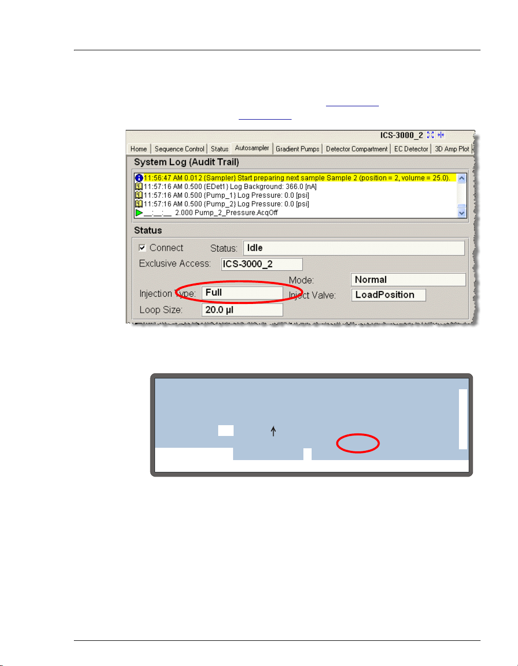
3 • Operation and Maintenance
During an injection, the injection type is displayed on the Chromeleon or
Chromeleon Xpress Control panel (see Figure 3-12
STATUS screen (see Figure 3-13).
Figure 3-12. Injection Type Shown on Control Panel
) and on the DETAIL
DETAIL
VIAL#:
INJ#:
METHOD:
TRAY:
1
1/3
01 P10 mL
20 °C
25
LOCAL
Help prompt
Figure 3-13. Injection Type Shown on Detail Status Screen
Doc. 065051-03 1/08 61
INJECTING
TIME:
VOL:
0.0
25
TRAY:
LOOP:
25.0
NORMAL FULL
SCH 1
LINE 1
min
uL
uL
TTL1
TTL2
RLY1
RLY2
INJ VLV
0
1
0
0
L
Page 74

AS Autosampler Operator’s Manual
3.6.2 Determining the Injection Type
To determine the injection type performed by the AS, first select the
sample mode on the
Menu, 5, and 5 to go to the SYSTEM PARAMETERS screen.
Press
METHOD SYRINGE SPEED:
CUT SEGMENT VOLUME:
INJECT PORT VOLUME:
FLUSH SYRINGE SPEED:
Help Prompt
SYSTEM PARAMETERS screen (see Figure 3-14).
SYSTEM PARAMETERS
SAMPLE MODE:
Figure 3-14. System Parameters Screen
The sample mode corresponds to the AS configuration. The following
sample modes are available:
• Normal—Sample is delivered to a single system; a sample loop is
installed on the injection valve.
WAIT:
ENABLED
3
10
uL
NORMAL
S1 43
4
uL
uLS2
• Concentrate—Sample is delivered to a single system; a concentrator
column is installed on the injection valve.
• Simultaneous—Sample is delivered to two systems simultaneously;
a sample loop is installed on both injection valves.
• Sequential—Sample is delivered to two systems alternately; a
sample loop is installed on both injection valves.
• Sequential concentrate—Sample is delivered to two systems
alternately; a concentrator column is installed on both injection
valves.
NOTE The SAMPLE MODE must be selected on the
SYSTEM PARAMETERS screen. It cannot be selected
from Chromeleon or Chromeleon Xpress.
If normal or sequential mode is selected, you must also enter additional
parameters to specify the type of sample loop injection performed (see
Section 3.6.3
62 Doc. 065051-03 1/08
).
Page 75

3 • Operation and Maintenance
3.6.3 Determining the Sample Loop Injection Type
When the AS is in normal or sequential mode, it can perform the
following types of sample loop injections:
• Full-loop—A full loop volume is injected.
• Large-loop—A full (large) loop volume is injected. Large loops are
200.0 to 7000.0
μL in volume.
• Partial-loop—A partial loop volume is injected.
• Partial-loop, limited-sample—A partial loop volume is injected; no
extra sample is aspirated from the vial or well.
NOTE When the AS is in simultaneous mode, it performs
only full-loop injections.
The following three parameters are used to determine the type of sample
loop injection the AS performs: cut volume, injection volume, and loop
size (see Table 3-4)
.
Criteria for Determining the
Sample Loop Injection Type
Injection volume ≥ loop size
(loop size = 2.5 to 199.9 μL)
Injection volume ≥ loop size
(loop size = 200.0 to 7000.0 μL)
Injection volume < loop size
(cut volume > 0)
Injection volume < loop size
(cut volume = 0)
Table 3-4. Determining the Sample Loop Injection Type
Type of Sample Loop Injection
Performed
Full-loop
Large-loop
Partial-loop
Partial-loop, limited-sample
The cut volume, which is used only for partial-loop and partial-loop,
limited-sample injections, specifies a volume of sample to be “cut” (or
omitted) from each side of the sample during the injection process. Using
a smaller cut volume minimizes the amount of total sample aspirated from
the vial or well. However, better precision is achieved with a larger cut
volume. If you enter a cut volume of 0, the AS draws only the injection
volume from the vial or well.
Doc. 065051-03 1/08 63
Page 76

AS Autosampler Operator’s Manual
1. Enter the size of the installed loop on the PLUMBING CONFIGURATION
screen (see Figure 3-15
CONFIGURATION screen.
SAMPLE SYRINGE VOLUME:
SAMPLE SYRINGE CONFIG:
PREP SYRINGE VOLUME:
PREP SYRINGE CONFIG:
Help Prompt
Figure 3-15. Plumbing Configuration Screen
2. Enter the injection volume in the Chromeleon or Chromeleon Xpress
sequence (see Figure 3-16
Section D.3
).
). Press Menu, 5, and 3 to go to the PLUMBING
PLUMBING CONFIGURATION
LOOP SIZE V1:
LOOP SIZE V2:
25
uL
uL
250
uL
READY
5
READY
mL
) or in the front panel schedule (see
Figure 3-16. Sequence Wizard: Specifying the Injection Volume
64 Doc. 065051-03 1/08
Page 77

3 • Operation and Maintenance
• If you enter an injection volume equal to or larger than the
installed loop size, the AS performs a full-loop (or large-loop)
injection.
• If you enter an injection volume smaller than the loop size, the
AS performs a partial-loop or partial-loop, limited-sample
injection.
3. Enter the cut volume
program (see Figure 3-17
(see Section C.6.5
NOTE The cut volume is used only for partial-loop or
partial-loop, limited-sample injections. For full-loop
or large-loop injections, the cut volume is ignored.
See page 63
in the Chromeleon or Chromeleon Xpress
) or on the SYSTEM PARAMETERS screen
).
for details about cut volumes.
Figure 3-17. Program Wizard: Specifying the Cut Volume
Doc. 065051-03 1/08 65
Page 78

AS Autosampler Operator’s Manual
3.6.4 Guidelines for Sample Volumes Used, Loop Sizes, and Injection Volumes
Sample Volumes Used for Each Type of Sample Loop Injection
Table 3- 5 shows the volume of sample the AS aspirates from the sample
vial or well plate well and the volume of sample injected onto the column.
Injection Type Sample Volume Aspirated
from Vial or Well
Full-loop
(2.5–16.9 μL loop)
Full-loop
(17.0–199.9 μL loop)
Large-loop
(200.0–7000.0 μL loop)
Partial-loop Injection volume + 2 × cut
Partial-loop, limitedsample
Table 3-5. Sample Volumes Used for Each Injection Type
See Section 3.6.3
for descriptions of sample loop injection types and the
Injection volume or
2.5 × loop size + 25 μL
(whichever is greater)
Injection volume or
4 × loop size
(whichever is greater)
Injection volume or
1 × loop size + 500 μL
(whichever is greater)
volume
Injection volume Injection volume
Sample Volume
Injected
Loop size
Loop size
Loop size
Injection volume
criteria used to determine which type of injection is performed.
The following tables give several examples for full-loop, large-loop, and
partial-loop injections. The examples show the amount of sample used
and injected for various loop sizes and injection volumes.
66 Doc. 065051-03 1/08
Page 79

3 • Operation and Maintenance
Full-Loop Sample Volume Examples
For full-loop injections, if the injection volume is more than 4 times the
loop size, the full injection volume is aspirated. The excess aspirated
sample is flushed through the loop, but the amount injected is equal to the
loop size.
Installed Loop
Size (
μL)
Injection
Volume from
Chromeleon
Sequence (μL)
Sample
Aspirated from
Vial or Well
a
μL)
(
Sample Volume
Injected onto
Column (μL)
10 10 40 10
10 35 40 10
10 60 60 10
25 25 100 25
25 75 100 25
25 150 150 25
Table 3-6. Full-Loop Sample Volume Examples
a. Excess aspirated sample is used to flush the loop before and after injection.
Large-Loop Sample Volume Examples
For large-loop injections, if the injection volume exceeds the loop size +
μl, the full injection volume is aspirated. The excess sample aspirated
500
is flushed through the loop, but the amount actually injected is equal to
the loop size.
Installed Loop
Size (
μL)
Injection
Vol ume from
Chromeleon
Sequence (μL)
Sample
Aspirated from
Vial or Well
a
μL)
(
Sample Volume
Injected onto
Column (μL)
500 500 1,000 500
500 700 1,000 500
500 1,100 1,100 500
Table 3-7. Large-Loop Sample Volume Examples
a. Excess aspirated sample is used to flush the loop before and after injection.
Doc. 065051-03 1/08 67
Page 80

AS Autosampler Operator’s Manual
Partial-Loop and Partial-Loop, Limited-Sample Volume Examples
For partial-loop injections, the amount of sample aspirated is equal to the
injection volume + 2
to the injection volume.
For partial-loop, limited-sample injections, the amount of sample
aspirated and injected is equal to the injection volume.
times the cut volume. The amount injected is equal
Installed
Loop Size
(
μL)
25 10
25 20
25 10
25 20
Table 3-8. Partial-Loop and Partial-Loop, Limited-Sample
a. The cut volume specifies a volume of sample to be “cut” (or omitted) from
each side of the sample during the injection process. See Section 3.6.3
details.
Maximum Sample Loop Sizes and Injection Volumes
Injection
Vol ume from
Chromeleon
Sequence (μL)
Sample Volume Examples
Cut
Volu me
a
μL)
(
5
10
0
0
Sample
Aspirated
from Vial or
Well (μL)
Sample
Volume
Injected onto
Column (μL)
20 10
40 20
10 10
20 20
for
The maximum loop size allowed depends on which sample syringe and
sampling needle assembly are installed. If the sample loop is too large, the
sample volume drawn exceeds the syringe/sampling needle assembly
volume, causing sample to enter the flush bottle.To prevent sample from
contaminating the flush bottle, the sample loop size must not exceed the
values shown in Tab le 3-9
.
68 Doc. 065051-03 1/08
Page 81

3 • Operation and Maintenance
Table 3- 9 also lists the maximum injection volume that can be specified in
the Chromeleon or Chromeleon Xpress sequence or in the front panel
schedule.
Sample
Syringe
≤1,000 μL1.2mL 500μL
5mL 8.5mL 4,000μL
10 mL 8.5 mL 7,000 μL
Table 3-9. Maximum Sample Loop Sizes and Injection Volumes
a. Requires a 1.5 mL vial or a 2 mL deep well plate.
b. Requires a 10 mL vial.
Notes
Sampling
Needle Assembly
Maximum Sample
Loop Size
a
b
b
Maximum
Injection Volume
1,100 μL
4,700 μL
8,000 μL
• To minimize the backpressure applied to the sample syringe pump,
use the largest ID tubing possible to make the injection loop.
• If a 1.5 mL vial is used, the maximum loop size is 500 μL and the
maximum injection volume is 1100
μL, regardless of the syringe size.
• For syringes that are 1,000 μL or smaller, the maximum loop size and
injection volume requires the syringe to aspirate from the sample vial
multiple times. This can result in reduced precision. For maximum
precision, use a loop size and injection volume that require only a
single sample aspiration.
Doc. 065051-03 1/08 69
Page 82
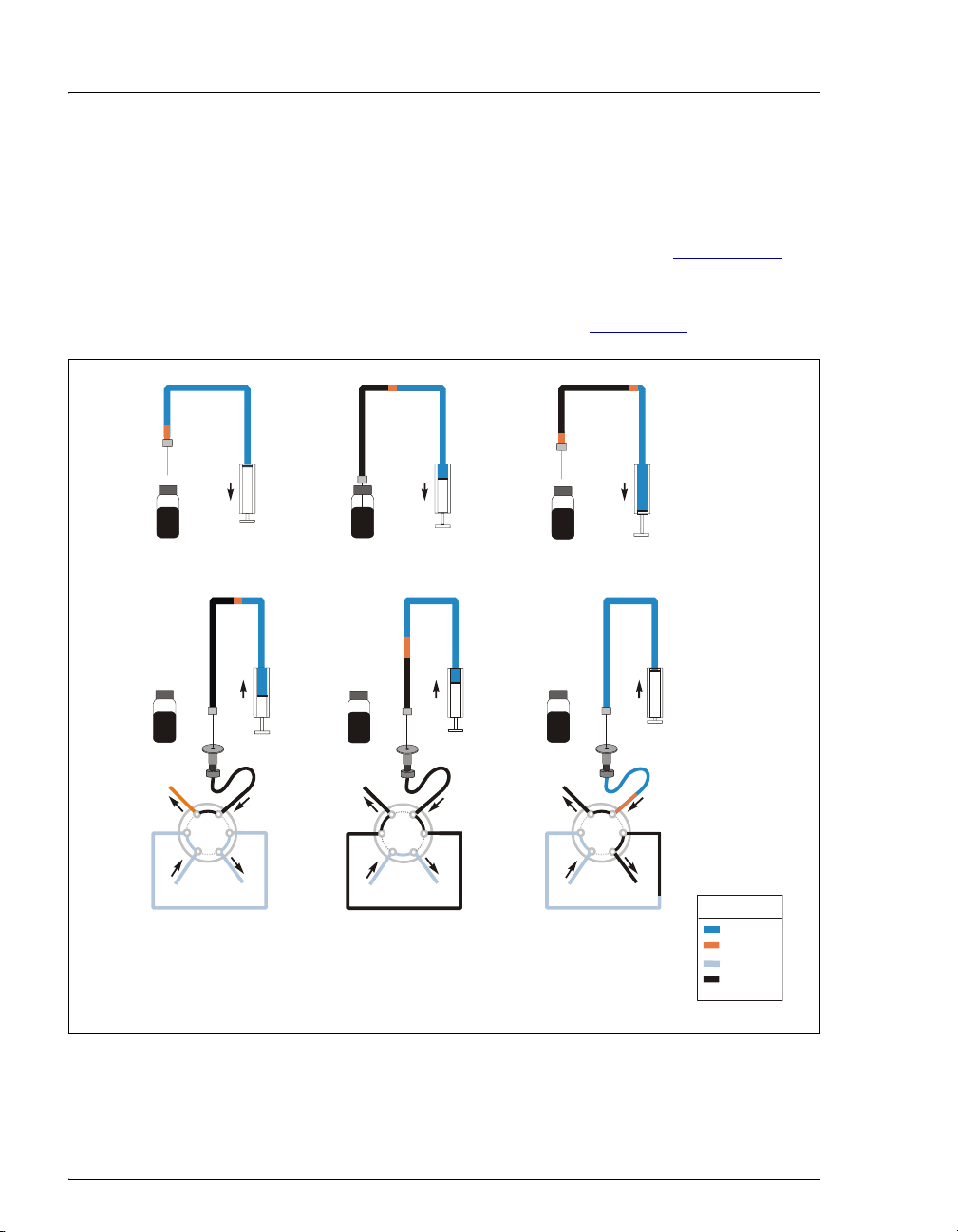
AS Autosampler Operator’s Manual
)
3.6.5 Normal, Full-Loop Injections
For a normal, full-loop injection, the AS draws a volume of sample from
the sample vial or well plate well. The volume of sample drawn depends
on the loop size and the specified injection volume (see Section 3.6.4
details). A portion of the sample is flushed through the loop, the loop is
filled, and an additional portion remains before the loop. The sample in
the loop is then injected onto the column (see Figure 3-18
Flush
Air
Sample
Syringe
Sample
for
).
1. Draw air
2. Draw sample
3. Draw air again to
isolate the sample
Waste Waste Waste
W
S
L
Pump
INJECT
P
L
C
Column
4. Prepare to load
sample (excess
sample used)
W
S
L
Pump
P
LOAD
L
C
Column
5. Deliver sample
to the loop (excess
sample sent to
waste)
Figure 3-18. Full-Loop Injection Sequence
W
S
L
Pump
INJECT
P
L
C
Column
6. Inject sample
onto column. Empty
syringe (remaining
sample + air bubble
KEY
Flush
Air
Eluent
Sample
70 Doc. 065051-03 1/08
Page 83

3 • Operation and Maintenance
Setting Up a Full-Loop Injection
1. On the SYSTEM PARAMETERS screen (see Section C.6.5), select
NORMAL in the SAMPLE MODE field.
2. In the Chromeleon or Chromeleon Xpress sequence (see Figure 3-19
or in the front panel schedule (see Section D.3
), enter an injection
volume equal to or greater than the volume of the loop installed on
the injection valve.
)
Figure 3-19. Sequence Wizard: Specifying the Injection Volume
Full-Loop Injection Notes
• Entering an injection volume equal to or greater than the sample loop
size sets up the AS for a full-loop injection. The actual volume of
sample injected equals the volume of the sample loop installed.
• If the entered injection volume is more than four times the loop size,
the entire injection volume is delivered during loading of the loop.
For example, if a 100
600
μL, then 350 μL is flushed through the loop, 100 μL is loaded
into the loop, and 150
Doc. 065051-03 1/08 71
μL loop is installed and the injection volume is
μL remains before the loop.
Page 84

AS Autosampler Operator’s Manual
Example Program for Normal Mode
The following example Chromeleon or Chromeleon Xpress program
shows the AS commands for sample loading and injecting when the
autosampler is in normal mode (full-loop, partial-loop, or partial-loop,
limited sample).
0.000 Load ;Switch the inject valve to Load
and load sample onto the loop
Wait CycleTimeState ;Wait for the end of the specified
Cycle Time
Inject ;Switch the inject valve to Inject
and sweep the sample onto the
column
Wait InjectState ;Wait for the injection to finish
3.6.6 Normal, Large-Loop Injections
The injection sequence for a normal, large-loop injection is the same as
described for a normal, full-loop injection (see Section 3.6.5
when a large loop (200.0 to 7000.0 μL)
amount (500
μL) of extra sample from the vial for flushing the loop,
instead of drawing a factor of the loop volume (see Section 3.6.4
details).
is installed, the AS draws a set
). However,
for
72 Doc. 065051-03 1/08
Page 85
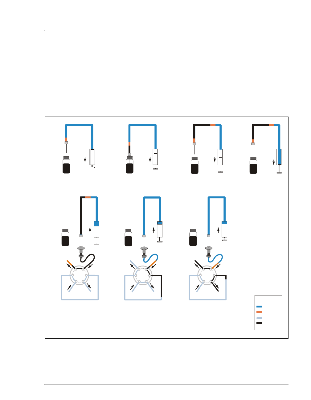
3 • Operation and Maintenance
3.6.7 Normal, Partial-Loop Injections
For a partial-loop injection, the AS draws the volume of sample to be
injected from the sample vial plus two times the cut volume.The cut
volume specifies a volume of sample to be “cut” (or omitted) from each
side of the sample during the injection process.
details. The middle portion of the sample is positioned in the loop and
).
3. Draw air again to
isolate the sample.
Flush
Air
Sample
1. Draw air
injected (see Figure 3-20
Sample
Syringe
2. Draw sample
(injection volume
+ 2X cut volume)
See Section 3.6.3 for
4. Draw flush
fluid to position
sample in loop.
Waste Waste Waste
W
S
L
Pump
INJECT
P
L
C
Column
5. Prepare to load
sample (flush fluid +
air bubble + cut
volume #1 is used)
W
S
L
Pump
P
LOAD
L
C
Column
6. Deliver sample
(inject volume)
the loop
to
W
S
L
Pump
INJECT
P
L
C
Column
7. Inject sample
onto column. Empty
sample syringe (cut
volume #2 + air bubble)
KEY
Flush
Air
Eluent
Sample
Figure 3-20. Partial-Loop Injection Sequence
Doc. 065051-03 1/08 73
Page 86

AS Autosampler Operator’s Manual
Setting Up a Partial-Loop Injection
1. On the SYSTEM PARAMETERS screen (see Section C.6.5), select
NORMAL in the SAMPLE MODE field.
2. In the Chromeleon or Chromeleon Xpress sequence (see Figure 3-19
or in the front panel schedule (see Section D.3
), enter an injection
volume that is less than the volume of the sample loop installed on the
injection valve.
3. In the Chromeleon or Chromeleon Xpress program (see Figure 3-21
or on the
SYSTEM PARAMETERS screen, enter a cut volume greater
than zero.
)
),
Figure 3-21. Program Wizard: Specifying the Cut Volume
NOTE For the best accuracy when performing partial-loop
injections, specify an injection volume equal to half
the loop size or less.
74 Doc. 065051-03 1/08
Page 87

3 • Operation and Maintenance
Example Partial-Loop Injection Parameters:
Sample loop size: 100
Injection volume: 50
Cut volume: 20
To perform the injection, the AS aspirates 90
μL
μL
μL
μL from the sample vial
(the inject volume plus double the cut volume) and delivers it to the
injection valve. Then, enough flush fluid is drawn into the syringe to
position the sample. One cut volume (20
next 50
μL is loaded into the loop. At injection, 50 μL is injected.
After injection, the remaining cut volume (20
μL) flows to waste and the
μL) flows to waste.
Doc. 065051-03 1/08 75
Page 88
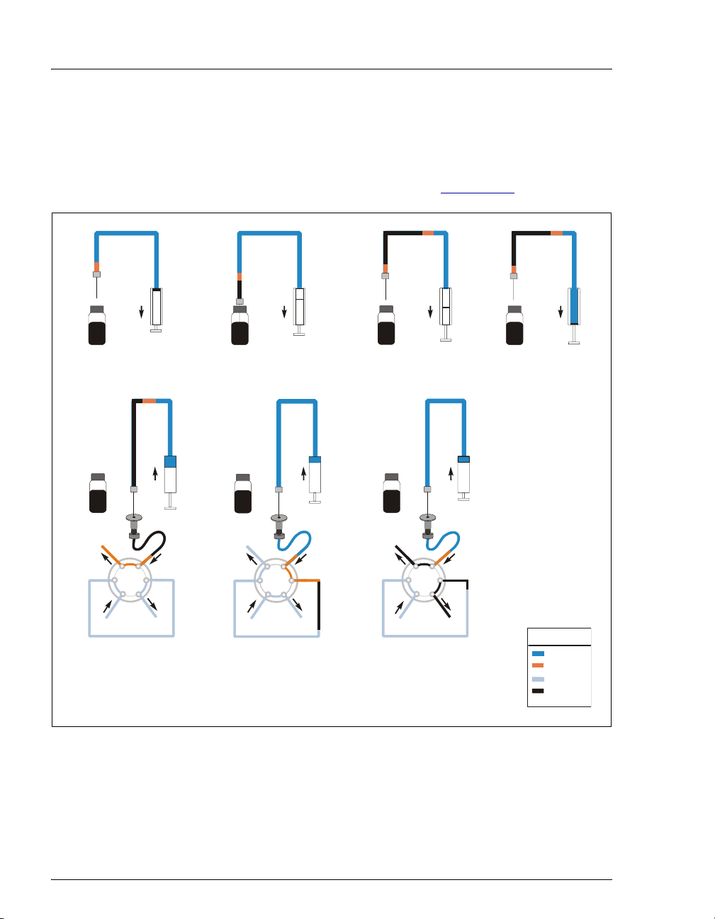
AS Autosampler Operator’s Manual
y
)
3.6.8 Normal, Partial-Loop, Limited-Sample Injections
For a partial-loop, limited-sample injection, the AS draws only the
volume to be injected from the sample vial. The AS positions the sample
in the loop and injects it onto the column (see Figure 3-22
Flush
Air
Sample
Syringe
Sample
).
1. Draw air
2. Draw sample
(injection volume)
Waste Waste Waste
W
S
L
Pump
INJECT
P
L
C
Column
5. Prepare to load
sample (flush fluid +
air bubble is used)
W
S
L
Pump
P
LOAD
L
C
Column
6. Deliver sample
(injection volume)
the loop
to
3. Draw air again to
isolate the sample.
7. Inject sample
onto column. Empty
sample syringe (air
bubble + an
Figure 3-22. Partial-Loop, Limited-Sample Injection Sequence
L
Pump
W
P
INJECT
S
L
C
Column
excess fluid
4. Draw flush
fluid for cleaning
inject port.
KEY
Flush
Air
Eluent
Sample
76 Doc. 065051-03 1/08
Page 89

3 • Operation and Maintenance
Setting Up a Partial-Loop, Limited-Sample Injection
1. On the SYSTEM PARAMETERS screen (see Section C.6.5), select
NORMAL in the SAMPLE MODE field.
2. In the Chromeleon or Chromeleon Xpress sequence (see Figure 3-19
or in the front panel schedule (see Section D.3
), enter an injection
volume that is less than the volume of the sample loop installed on the
injection valve.
3. In the Chromeleon or Chromeleon Xpress program (see Figure 3-21
or on the
SYSTEM PARAMETERS screen, enter a cut volume of zero.
Example Partial-Loop, Limited-Sample Injection Parameters:
Sample loop size: 100
Injection volume: 50
Cut volume: 0
μL
To perform the injection, the AS aspirates 50
μL
μL
μL from the sample vial
(the inject volume) and then enough flush fluid is drawn into the
syringe to position the sample. The 50
μL of sample is positioned just
before the loop and is then loaded onto the loop and injected.
)
),
Doc. 065051-03 1/08 77
Page 90

AS Autosampler Operator’s Manual
)
3.6.9 Simultaneous Injections
The AS must be in simultaneous mode to perform a simultaneous
injection (see Section 3.6.2
volumes of sample to two injection valves (see Figure 3-23
injection is a full-loop size.
Flush
Air
Sample
Syringe
Sample
1. Draw air 3. Draw air again to
2. Draw sample
(inject volume)
). In simultaneous mode, the AS delivers equal
). Each
isolate the sample
Waste
L
Pump
Inject Valve #1
S
W
P
LOAD
C
Column
Waste
L
L
Pump
Inject Valve #2
4. Deliver 1/2 of sample
to the loop of each inject valve
W
P
LOAD
S
C
Column
Waste Waste
W
L
L
P
Pump
INJECT
Inject Valve #1
5. Inject sample simultaneously
onto both system’s columns.
Empty sample syringe (remaining
S
L
C
Column
S
W
L
P
C
Column
Pump
INJECT
Inject Valve #2
L
KEY
Flush
Air
Eluent
Sample
sample + air bubble
Figure 3-23. Simultaneous Injection Sequence
78 Doc. 065051-03 1/08
Page 91

3 • Operation and Maintenance
Setting Up a Simultaneous Injection
The AS must be equipped with the simultaneous injection option in order
to perform simultaneous injections. The following setup steps are
required:
• Follow the instructions in Section B.3.5 to connect the AS to two
injection valves (either in the autosampler compartment or two IC
systems). In this configuration, the inject port tubing is connected to a
Y-connector and the legs of the Y are connected to the inject valves in
both systems (see Figure 3-23
). The tubing from the Y to each valve
must be the same length.
• Install a sample syringe of 5,000 or 10,000 μL.
• Enter the sample syringe size of 5,000 or 10,000 μL on the
PLUMBING CONFIGURATION screen (see Section C.6.3).
• On the SYSTEM PARAMETERS screen (see Section C.6.5), select
SIMULTANEOUS in the SAMPLE MODE field.
• In the Chromeleon or Chromeleon Xpress sequence (see Figure 3-19)
or in the front panel schedule (see Section D.3
volume that is large enough to allow flushing the inject port, flushing
the tubing from the inject port to each valve (25
tubing), plus enough to flush and fill both injection loops (this is
about 5 times the combined loop sizes).
), enter an injection
μL per inch of
Example Simultaneous Injection Parameters:
45
μL = inject port volume
μL = 20 inches of connector tubing (combined from both
500
systems) x 25
625
μL = 5 x (100 μL loop #1 + 25 μL loop #2)
total = 1170
μL
μL
The specified injection volume is loaded into the sample syringe and
then delivered equally to the two sample loops.
Doc. 065051-03 1/08 79
Page 92

AS Autosampler Operator’s Manual
Example Program for Simultaneous Mode
The following example Chromeleon or Chromeleon Xpress programs
show the AS commands for sample loading and injecting when the
autosampler is in simultaneous mode. Commands differ slightly,
depending on where the valves are installed.
Example Simultaneous Injection Program: Two Valves Installed in
the AS
0.000 Sampler_InjectValve.LoadPosition ;Switch the first inject
valve to Load
Sampler_InjectValve_2.LoadPosition ;Switch the second
inject valve to Load
Load ;Load sample onto the
loop
Wait CycleTimeState ;Wait for the end of the
specified Cycle Time
Sampler_InjectValve.InjectPosition ;Switch the first inject
valve to Inject
Sampler_InjectValve_2.InjectPosition ;Switch the second
inject valve to Inject
Inject ;Sweep the sample onto
the column
Wait InjectState ;Wait for the injection to
finish
Example Simultaneous Injection Program: Two Valves Installed in
an ICS-3000 Detector/Chromatography Module
0.000 InjectValve_1.LoadPosition ;Switch the first inject
valve to Load
InjectValve_2.LoadPosition ;Switch the second
inject valve to Load
Load ;Load sample onto the
loop
Wait CycleTimeState ;Wait for the end of the
specified Cycle Time
80 Doc. 065051-03 1/08
Page 93

3 • Operation and Maintenance
InjectValve_1.InjectPosition ;Switch the first inject
valve to Inject
InjectValve_2.InjectPosition ;Switch the second
inject valve to Inject
Inject ;Sweep the sample onto
the column
Wait InjectState ;Wait for the injection to
finish
Example Simultaneous Injection Program: Two Valves Installed in
an ICS-1000/1500/2000
0.000 Pump_InjectValve.LoadPosition ;Switch the first inject
valve to Load
Pump_InjectValve_2.LoadPosition ;Switch the second
inject valve to Load
Load ;Load sample onto the
loop
Wait CycleTimeState ;Wait for the end of the
specified Cycle Time
Pump_InjectValve.InjectPosition ;Switch the first inject
valve to Inject
Pump_InjectValve_2.InjectPosition ;Switch the second
inject valve to Inject
Inject ;Sweep the sample onto
the column
Wait InjectState ;Wait for the injection to
finish
Doc. 065051-03 1/08 81
Page 94

AS Autosampler Operator’s Manual
3.6.10 Concentrate Injections
The AS must be in concentrate mode to perform a concentrate injection
). In concentrate mode, the AS draws the volume to be
). The example in Figure 3-24 also shows the reagent prime
Flush
Sample
Air
(see Section 3.6.2
injected from the sample vial and delivers it to a concentrator column (see
Figure 3-24
and reagent flush steps for matrix elimination.
Sample
Syringe
3. Draw air again to
isolate the sample
Reagent
Waste
W
L
Pump
Concentrator
LOAD
6. Flush concentrator
with reagent (matrix
elimination)
Sample
Eluent
P
S
L
C
Column
Waste
Pump
7. Inject sample
onto column
ReagentAir
Waste
Waste
1. Draw air
W
L
P
Pump
Concentrator
LOAD
S
L
C
Column
2. Draw sample
(inject volume)
Reagent
S
Waste
Waste
Port
W
L
Pump
Concentrator
LOAD
5
. Prime sampling
P
S
L
C
Column
needle assembly
line
with reagent
KEY
DI Water
Figure 3-24. Concentrate Injection Sequence (Example for Matrix Elimination)
W
S
L
P
C
Column
Concentrator
INJECT
L
82 Doc. 065051-03 1/08
Page 95

3 • Operation and Maintenance
Setting Up a Concentrate Mode Injection
1. Install a concentrator column on the injection valve.
2. If the sample syringe volume is greater than 1 mL, install an 8.5 mL
sampling needle assembly (P/N 061267). See Section 5.4
installation instructions.
for
3. On the
SAMPLE MODE field.
4. For front panel control, select
SYRINGE
SYSTEM PARAMETERS screen, select CONCENTRATE in the
METHOD SYRINGE and FLUSH
speeds on the SYSTEM PARAMETERS screen.
5. For Chromeleon or Chromeleon Xpress control, enter the syringe
speed in the Program Wizard. 1 is the slowest speed and 5 is the
fastest. You can enter separate aspirate and dispense speeds for the
Concentrate, Reagent Flush, and Reagent Prime functions. In general,
use a faster speed for aspirating and a slower speed for dispensing
fluid to the concentrator. See Section 3.7
for details about selecting
syringe speeds.
NOTE If a 5 or 10 mL syringe is installed, the dispense
speed is limited to speed 1 or 2 only.
Doc. 065051-03 1/08 83
Page 96

AS Autosampler Operator’s Manual
Figure 3-25 shows the Program Wizard Sampler Options tab page
with the Concentrate function selected.
Figure 3-25. Program Wizard Sampler Options for Concentrate
NOTE Be sure to select syringe speeds that will keep the
backpressure below 690 kPa (100 psi), taking into
account the pressure from the tubing and the
concentrator column. See Section 3.8
for details.
6. In the Chromeleon or Chromeleon Xpress sequence (see Figure 3-19)
or in the front panel schedule (see Section D.3
), enter an injection
volume equal to the amount of sample to be loaded onto the
concentrator.
84 Doc. 065051-03 1/08
Page 97

Example Program for Concentrate Mode (Matrix Elimination)
The following example Chromeleon or Chromeleon Xpress program
shows the AS commands when the autosampler is in concentrate mode.
Commands similar to these could be used for a matrix elimination
application.
Flush Volume = 100 ;AS options commands
Wait FlushState
NeedleHeight = 2
CutSegmentVolume = 0
SyringeSpeed = 3
CycleTime = 0
Pipet Volume = 20.0, SourceVial =
CurrentVial, DestinationVial =
CurrentVial
Mix SourceVial = CurrentVial,
NumberOfTimes = 5, Volume = 250.0
FlushSP Volume = 250.0
DelaySP Time = 0.0
Dispense Volume = 1000.0,
SourceReservoir = Reservoir_A,
DestinationVial = CurrentVial
WaitForTemperature = False
Concentrate ValvePosition =
LoadPosition, AspirateSpeed = 3,
DispenseSpeed = 1
ReagentPrime Volume = 10000.0,
SourceVial = Reservoir_A, ValvePosition
= NoChange
ReagentFlush Volume = 5000.0, SourceVial
= Reservoir_A, ValvePosition = NoChange
Wait SampleReady
0.000 Wait CycleTimeState
3 • Operation and Maintenance
;AS sample prep
commands
;Switch the inject valve
to Load and load sample
onto the concentrator
;Prime sampling needle
assembly with reagent
;Flush concentrator with
reagent; this is the
matrix elimination step
Doc. 065051-03 1/08 85
Page 98

AS Autosampler Operator’s Manual
Sampler_InjectValve.InjectPosition ;Switch the inject valve
to Inject and sweep the
sample onto the column
5.000 BeginOverlap ;Start preparing the next
sample in the sequence
(see note below)
30.000 End
NOTE If the AS is in concentrate mode, sample preparation
overlap is available only if the autosampler is controlled
by Chromeleon or Chromeleon Xpress. If the AS is
under front panel control, sample overlap is not
available.
3.6.11 Sequential Injections
The AS must be in sequential mode to perform sequential injections (see
Section 3.6.2
separate chromatography systems. Each system is operated independently
and can have a different sample and sample volume injected.
). In sequential mode, the AS delivers sample to two
NOTE Precision for partial-loop injections may be slightly
affected by the longer tubing length from the inject
port to the injection valve.
NOTE Figure 3-26
When the diverter valve is switched to position 2,
the injection sequence is identical, except that flow
is diverted to inject valve #2.
86 Doc. 065051-03 1/08
shows an injection to inject valve #1.
Page 99

.
Flush
Sample
Air
Sample
Syringe
3 • Operation and Maintenance
1. Draw air
PP
Diverter Valve
Waste
L
Pump
Inject Valve #1
W
P
INJECT
1
S
L
C
Column
S
2
Waste
Pump
4. Prepare to load sample
(excess sample used). Diverter
valve selects inject valve #1 or #2.
P
W
S
L
P
C
Column
INJECT
Inject Valve #2
2. Draw sample (at
least 4X loop volume)
PP
1
Waste Waste
L
L
Pump
Inject Valve #1
S
W
P
LOAD
P
2
S
L
C
Column
To Inject
Valve #2
5. Deliver sample
to the loop (excess
sample sent to waste)
3. Draw air again to
isolate the sample
PP
1
1
2
Pump
Inject Valve #1
S
6
INJECT
P
2
5
4
3
Column
To Inject
Valve #2
6. Inject sample onto column
Empty syringe (remaining
sample + air bubble)
KEY
Flush
Eluent
Sample
Unselected ValveAir
Figure 3-26. Sequential, Full-Loop Injection Sequence
NOTE Partial-loop and partial-loop, limited-sample injections
can also be performed in sequential mode. The
sequences of events for these injection types are the
same as for normal mode, except for selection of the
diverter valve position.
Doc. 065051-03 1/08 87
Page 100

AS Autosampler Operator’s Manual
Setting Up a Sequential Mode Injection
The AS must be equipped with the sequential injection option
(P/N 063294) in order to perform sequential injections. The following
setup steps are required:
1. Follow the instructions in Section B.3.6
to install the sequential
injection diverter valve, connect the AS inject port tubing to the
diverter valve, and connect the diverter valve to the injection valves
on two systems.
2. Calibrate the inject port volume of each system. This is the volume
from the inject port through the diverter valve to the injection valve
(see Section 5.9
3. On the
SAMPLE MODE field (see Figure 3-27).
METHOD SYRINGE SPEED:
Help Prompt
4. On the
SYSTEM PARAMETERS screen, select SEQUENTIAL in the
CUT SEGMENT VOLUME:
INJECT PORT VOLUME:
FLUSH SYRINGE SPEED:
Figure 3-27. System Parameters Screen: Sequential Mode
PLUMBING CONFIGURATION screen, enter the sample loop size
installed on each valve (see Figure 3-28
).
SYSTEM PARAMETERS
WAIT:
SAMPLE MODE:
ENABLED
3
10
uL
SEQUENTIAL
S1 43
4
uL
S2 47
).
uL
PLUMBING CONFIGURATION
uL
LOOP SIZE V1:
LOOP SIZE V2:
SAMPLE SYRINGE VOLUME:
SAMPLE SYRINGE CONFIG:
PREP SYRINGE VOLUME:
PREP SYRINGE CONFIG:
Help Prompt
Figure 3-28. Plumbing Configuration Screen: Sequential Mode
88 Doc. 065051-03 1/08
25
100
uL
250
READY
READY
uL
5
mL
 Loading...