

Dion-Ag F41 Operator's Manual
F41
05/12/14
Operator’s Manual
Forage Harvester
Manual No. F4112E952 V1.2
1

DION-AG INC. LIMITED WARRANTY TERMS AND CONDITIONS
Covered by Warranty – Under the warranty, Dion-Ag guarantees its new machinery and/or equipment to
be free of defects, both in workmanship and material, for a period of one (1) year from the time of delivery by
the dealer. Dion-Ag Inc. will repair or replace, at its discretion and without charge for service parts or labour,
any defective part of the equipment on condition that the machinery and/or equipment has been operated
in accordance with the instructions contained in the Dion-Ag Inc. Operator’s Manual.
Not covered by Warranty – This warranty does not cover: (1) service parts and labour needed to maintain the unit; and (2) the replacement of parts due to normal wear and tear. The owner is responsible for
these items. Some examples of maintenance and normal wear parts are: oil, lubricants & other uids, belts,
knives, clutch and clutch discs, roller chain, paddles, etc. Dion-Ag Inc. is not responsible for depreciation or
damage caused by normal wear, lack of reasonable and proper maintenance, failure to follow operating instructions, misuse, lack of proper protection during storage, vandalism, the elements, collision or accident.
Securing Warranty Service – To secure warranty service, the purchaser must report the machinery and/
or equipment defect to an authorized dealer and request warranty service within the applicable warranty
terms.
Owner’s Obligation – It is the responsibility of the Owner to transport the equipment to the service shop of
an authorized Dion-Ag Dealer or to reimburse the dealer for any travel or transportation expense involved
in fullling this warranty. This warranty does NOT cover rental of replacement equipment during the repair
period, loss of prots, or other commercial loss, and any or all incidental or consequential damages, over-
time labour charges and/or freight charges for replacement parts.
Limitations of This Warranty – No agent, employee or representative of Dion-Ag Inc. has the authority to
amend, or modify, in any manner whatsoever, the terms of the present warranty. The express warranties
herein contained exclude all other express, implied or statutory warranties. THIS WARRANTY IS IN LIEU
OF ALL OTHER WARRANTIES INCLUDING THE WARRANTIES OF MERCHANTABILITY AND/OR FITNESS FOR ANY PARTICULAR PURPOSE.
Right to Inspect – Dion-Ag and its authorized agents reserve the right to inspect the purchaser’s Dion-Ag
product to determine if a defect in material or workmanship exists prior the commencement of any covered
repairs. It is the purchaser’s responsibility to ensure availability and/or delivery of the product to Dion-Ag
for the purpose of inspection.
Right to Make Design Changes – Dion-ag reserves the right to make changes in the design and other
changes in its products at any time and from time to time without notice and without incurring any obligation
of its part to modify, improve or add to products previously ordered from Dion-Ag and sold or shipped by
Dion-Ag.
Liability – Dion-Ag Inc. shall not be liable, if, during the use of the machinery and/or attachment, the secu-
rity guards have been removed, modied, or have not been properly maintained.
The Warranty shall not apply if the instructions mentioned in this manual have not been followed comple-
tely and correctly. Nor will the warranty apply if the owner or any third party modies the machine without
Dion-AG’s knowledge and/or authorization. Every purchaser, when buying a Dion-Ag machine, agrees and
undertakes to use and operate the machinery and its component parts safely, and in accordance with all
applicable laws, and in accordance with the Operator’s Manual. Furthermore, the purchaser agrees and
accepts to indemnify and hold harmless Dion-Ag for all losses and damages to any person or property resulting from the purchaser’s non-compliance with the terms and conditions of this warranty. Each purchaser
further agrees to bring the warranty to the attention of any subsequent purchaser, and to obtain agreement
therein as a condition of resale or transfer.
2
Manual no. F4112E952 V1.2
FORAGE HARVESTER F41
TO OUR CUSTOMER
We appreciate your condence in Dion Farm Equipment and thank you for your trust. In preparing
this manual, we hope we have furnished you with a valuable tool for operating and maintaining
this ne machine. Use this manual as your guide. Practicing the instructions given here will result
in many years of dependable service from your machine.
Your dealer can give you assistance with parts and specially trained personnel to assist you in
repair and maintenance.
Call your dealer if you need any assistance or information.
Manual no. F4112E952 V1.2
3

TABLE OF CONTENTS
SPECIFICATIONS ....................................................................................................................................... 7
SERIAL NUMBER LOCATION .................................................................................................................. 9
CHECK LIST .............................................................................................................................................. 10
PRE-SEASON CHECKS ..................................................................................................................... 10
DAILY CHECKS .................................................................................................................................. 11
FOREWORD .............................................................................................................................................. 12
TO OUR CUSTOMER ........................................................................................................................... 12
THIS MANUAL SHOULD REMAIN WITH THE MACHINE WHEN SOLD ............................................ 12
WARRANTY INFORMATION ................................................................................................................ 12
WARRANTY ON THE METAL DETECTOR .......................................................................................... 12
SAFETY ................................................................................................................................................ 12
SAFETY RULES ........................................................................................................................................ 13
SAFETY ALERT SYMBOL .................................................................................................................... 13
FOLLOW A SAFETY PROGRAM ......................................................................................................... 13
A WORD TO THE OPERATOR ............................................................................................................. 13
PTO OPERATION ................................................................................................................................. 15
MANDATORY STOPPING PROCEDURE ............................................................................................ 15
GUARDS AND SHIELDS ...................................................................................................................... 16
SAFETY SIGN LOCATION ........................................................................................................................ 17
DELIVERY .................................................................................................................................................. 22
MATERIAL OR EQUIPMENT SUPPLIED WITH THE MACHINE ......................................................... 22
MATERIAL SUPPLIED SEPARATELY WITH THE MACHINE .............................................................. 22
HARVESTERS ARE SHIPPED TO OPERATE AS FOLLOWS ............................................................. 22
OPTIONAL EQUIPMENT CHOICES .................................................................................................... 22
MANUAL JACK ..................................................................................................................................... 22
ASSEMBLING INSTRUCTIONS ................................................................................................................ 23
RECEIVING YOUR FORAGE HARVESTER ........................................................................................ 23
PREPARING THE FORAGE HARVESTER .......................................................................................... 23
INSTALLING THE CONTROL BOX ...................................................................................................... 23
CONNECTING THE POWER-TAKE-OFF (PTO) .................................................................................. 25
INSTALLING THE STANDARD SPOUT ............................................................................................... 26
INSTALLING THE 12” (30 cm) SPOUT EXTENSION ........................................................................... 27
INSTALLING THE 24” (60 cm) SPOUT EXTENSION ........................................................................... 29
HOW TO MAKE THE ELECTRICAL CONNECTIONS ON THE SPOUT .............................................. 31
INSTALLING MUDGUARDS OVER TANDEM WHEELS ...................................................................... 32
INSTALLING AN ATTACHMENT ON THE FORAGE HARVESTER ..................................................... 33
INSTALLING THE RECUTTER BAR ASSEMBLY FOR CORN CROP ................................................. 35
INSTALLING THE GRAIN PAN AND FRONT RUBBER PAD ASSEMBLY FOR CORN CROP ........... 35
INSTALLING A LIGHT ON THE SPOUT DEFLECTOR ........................................................................ 36
INSTALLING THE INSPECTION LIGHT ............................................................................................... 37
ASSEMBLING INSTRUCTIONS - LIQUID INCORPORATION SYSTEM ................................................. 38
ASSEMBLING INSTRUCTIONS - MANUAL QUICK-DISCONNECT HITCH ........................................... 42
ASSEMBLING INSTRUCTIONS - ELECTRIC QUICK-DISCONNECT HITCH ......................................... 43
ASSEMBLING INSTRUCTIONS - DRAW BAR EXTENSION ................................................................... 45
ASSEMBLING INSTRUCTIONS - TRANSPORT LIGHTS ........................................................................ 47
CORN CRACKER INSTALLATION INSTRUCTIONS ............................................................................... 48
4
Manual no. F4112E952 V1.2

TABLE OF CONTENTS
PARTIAL DISMANTLING OF THE CORN CRACKER FOR HAY CROP ................................................. 63
PARTIAL reassembling OF THE CORN CRACKER FOR CORN CROP ................................................ 70
OPERATING INSTRUCTIONS .................................................................................................................. 75
OPERATION TIPS ................................................................................................................................ 75
BREAK-IN SPEED ................................................................................................................................ 75
BOLT TORQUE SPECIFICATIONS ...................................................................................................... 75
METAL DETECTOR .............................................................................................................................. 75
STOPPING THE MACHINE .................................................................................................................. 75
TRANSPORTATION ON PUBLIC ROADS ........................................................................................... 75
PREPARING FOR FIELD OPERATION ............................................................................................... 76
HITCHING THE FORAGE HARVESTER TO THE TRACTOR ............................................................. 76
ADJUSTING THE ATTACHMENT GROUND CLEARANCE ................................................................. 77
STARTING UP ...................................................................................................................................... 77
INFORMATION ON THE METAL DETECTOR ..................................................................................... 77
DAILY CHECKS ON THE METAL DETECTOR .................................................................................... 78
INITIALIZING THE METAL DETECTOR ............................................................................................... 79
STOPPING THE MACHINE .................................................................................................................. 79
STARTING OPERATION ...................................................................................................................... 80
THE CONTROL BOX ............................................................................................................................ 80
EMERGENCY STOP ............................................................................................................................ 80
WHAT TO DO WHEN THE MACHINE DETECTS A FERROUS METAL .............................................. 81
WHAT TO DO IF MATERIAL ACCUMULATION OCCURS (CLOGGING) ............................................ 81
HOW TO BY-PASS THE METAL DETECTOR ...................................................................................... 82
SHEAR BOLT ........................................................................................................................................ 83
PRESSURE AND FLOW CHARTS FOR STANDARD NOZZLE .......................................................... 84
HOW TO OPERATE THE LIQUID INCORPORATION SYSTEM ......................................................... 84
PRESSURE ADJUSTMENT ................................................................................................................. 84
DETECTION SYSTEM FOR SAFETY BOLT BREAKAGE OR FRICTION CLUTCH SLIPPAGE
ON THE CUTTER HEAD TRANSMISSION SHAFT
............................................................................. 85
LUBRICATION ........................................................................................................................................... 87
HYDRAULIC CIRCUIT ........................................................................................................................ 87
POWER-TAKE-OFF (PTO) ................................................................................................................. 87
LUBRICATION CHART ....................................................................................................................... 87
CHAINS ............................................................................................................................................... 87
GEAR BOX LUBRICATION ................................................................................................................. 87
CORN CRACKER LUBRICATION ...................................................................................................... 94
ADJUSTMENTS - MAINTENANCE ........................................................................................................... 96
WHEEL POSITIONING ......................................................................................................................... 96
GROUND CLEARANCE ....................................................................................................................... 97
DISMANTLING AND REASSEMBLY OF THE POWER-TAKE-OFF (PTO) ROTATING GUARDS ...... 97
FORAGE HARVESTER DRAW BAR .................................................................................................... 98
FEED ROLL BALANCING SPRINGS ................................................................................................... 98
UPPER FEED ROLL CHAIN TENSION ................................................................................................ 99
LOWER FEED ROLL CHAIN TENSION ............................................................................................... 99
STRAW CHOPPING ............................................................................................................................. 99
BALANCING SPRINGS ........................................................................................................................ 100
UPPER ROLL ADJUSTING BOLTS ...................................................................................................... 101
SPOUT WEAR PLATE .......................................................................................................................... 101
5
Manual no. F4112E952 V1.2

TABLE OF CONTENTS
MAGNETIC DRAIN PLUGS .................................................................................................................. 101
FEED ROLL STOPPING SYSTEM ....................................................................................................... 102
FAN BELT TENSION............................................................................................................................. 103
FAN AND TRANSMISSION BELT REPLACEMENT ............................................................................. 103
CORN CRACKER BELT TENSION ...................................................................................................... 104
CORN CRACKER BELT REPLACEMENT ........................................................................................... 105
TRANSMISSION BOX BELTS .............................................................................................................. 106
REVERSE, NEUTRAL AND FORWARD SPEEDS POSITIONS .......................................................... 106
ANGLE DRIVE TRANSMISSION BOX SHEAVE .................................................................................. 107
FAN ADJUSTMENT .............................................................................................................................. 108
KNIFE ADJUSTMENT ........................................................................................................................... 110
KNIFE GRINDING ................................................................................................................................. 111
KNIFE REPLACEMENT ........................................................................................................................ 113
KNIVES & SHEAR BAR GENERAL INFORMATION ............................................................................ 11 3
SHEAR BAR ADJUSTMENT ................................................................................................................ 114
DAILY ADJUSTMENT ........................................................................................................................... 114
REPLACEMENT AND INITIAL ADJUSTMENT OF THE SHEAR BAR ................................................ 115
CUTTING LENGTH SELECTION ......................................................................................................... 116
PROCEDURE FOR CHANGING THE CUTTING LENGTH ................................................................. 117
SMOOTH FEED ROLL CLEANER ADJUSTMENT ............................................................................... 117
MAINTENANCE PROCEDURE FOR THE CUTTER HEAD BOTTOM PLATE ASSEMBLY ................ 118
CORN CRACKER SHEAVE ALIGNMENT ............................................................................................ 119
CORN CRACKER Q.D. BUSHINGS ..................................................................................................... 120
CORN CRACKER LOWER ROLL BEARINGS ..................................................................................... 120
CORN CRACKER UPPER ROLL BEARINGS ...................................................................................... 122
CORN CRACKER LOWER ROLL HALF BOTTOM PLATE .................................................................. 124
CORN CRACKER LOWER ROLL PROTECTOR ................................................................................. 124
CORN CRACKER ROLL SCRAPER .................................................................................................... 125
UPPER CORN CRACKER ROLL “ZERO” POSITION ADJUSTMENT ................................................. 126
UPPER CRACKER ROLL PRESSURE AND GAP ADJUSTMENT ...................................................... 127
CORN CRACKER INITIAL START UP ADJUSTMENT ......................................................................... 128
LIFTING THE ATTACHMENT ............................................................................................................... 128
LIFTING ARMS ..................................................................................................................................... 128
STONE CARRIAGE ADJUSTMENT .................................................................................................... 129
STONE REPLACEMENT ...................................................................................................................... 129
CUTTER HEAD SENSOR ADJUSTMENT ........................................................................................... 130
FEED ROLL SHAFT SENSOR ADJUSTMENT .................................................................................... 130
PTO FRICTION CLUTCH ADJUSTMENT (OPTION) ........................................................................... 131
VENTING THE CLUTCH ...................................................................................................................... 132
CLUTCH DISMANTLING PROCEDURE .............................................................................................. 133
CLUTCH ASSEMBLY PROCEDURE .................................................................................................... 134
CLUTCH TORQUE SETTING ............................................................................................................... 135
TRANSMISSION CLUTCH LEVER POSITION SENSOR .................................................................... 136
STORAGE .................................................................................................................................................. 138
METAL DETECTOR DIAGNOSTIC SHORT PROCEDURE ...................................................................... 139
«LED» DISPLAY ON METAL DETECTOR ................................................................................................ 140
TROUBLESHOOTING ............................................................................................................................... 141
6
Manual no. F4112E952 V1.2

SPECIFICATIONS
Specifications and design are subject to change without notice
and without liability therefore.
WEIGHT (with 31 X 13.5 X 15” TERRA RIB tires)
with metal detector ..................................................................................... 5280 lbs (2400 Kg)
without metal detector ................................................................................ 5230 lbs (2380 Kg)
DIMENSIONS
Overall width:
with 31x13.50 tires - 15 Terra Rib 142” (361cm)
with 31x15.50 tires - 15 Terra Grip 150” (381 cm)
length ...........................................................................................................228” (579 cm)
height ...........................................................................................................129” (328 cm)
ANGLE DRIVE TRANSMISSION
540 or 1000 RPM (buyer’s choice)
MAIN TRANSMISSION
forward-neutral-reverse with torque limiter
three lengths of cut
OPERATING CAPACITY
540 RPM to 730 RPM - 90 to 135 HP
1000 RPM to 815 RPM - 90 to 180 HP
1000 RPM to 1033 RPM - 160 to 300 HP
ELECTRICAL CONTROLS
transmission
spout (240˚ rotation)
deector
CUTTER HEAD
12 helicoidal knives
24” (61 cm) wide
22” (56 cm) diameter
speed: 815 to 1033 RPM
TIRES AND SINGLE WHEELS
31 X 13.5 X 15” TERRA RIB
16.5 X 16.1 - 8 ply DYNA RIB
TIRES AND TANDEM WHEELS
31 X 3.50 - 15 TERRA RIB
31 X 15.50 - 15 HIPPO
Manual no. F4112E952 V1.2
7

SPECIFICATIONS
Specifications and design are subject to change without notice
and without liability therefore.
STANDARD EQUIPMENT
Hydraulic lift control
Hydraulic tongue control
Cutting edges of the cylinder knives with tungsten carbide treatment
Built-in grinder
Transmission, spout and deector electrical controls
Double sprocket wheel for lengths of cut: 26 teeth for 3/8” (9.5 mm) standard upon delivery
and 34 teeth for 1/2” (13 mm)
Shear bar adjustment on one side
240o rotation spout
OPTIONAL EQUIPMENT
Metal detector
Spout extension (12” or 24”) (30 or 60 cm)
Single wheels or tandem wheels
Double sprocket wheels for lengths of cut: 17 teeth for 1/4” (6.35 mm)
Deector light
Inspection light
Manual (cord) quick-disconnect hitch
Electrical heavy-duty quick-disconnect hitch
Liquid incorporation system
Recuperation grain pan
Recuter bar (for corn only)
Corn Cracker
Draw Bar Hooker
Draw Bar Extension
OIL CAPACITY
Angle drive transmission: 1.8 imperial gallons - 2.0 US gallons - 8 liters
Main transmission: 0.88 imperial gallon - 1.1 US gallons - 4 liters
8
Manual no. F4112E952 V1.2
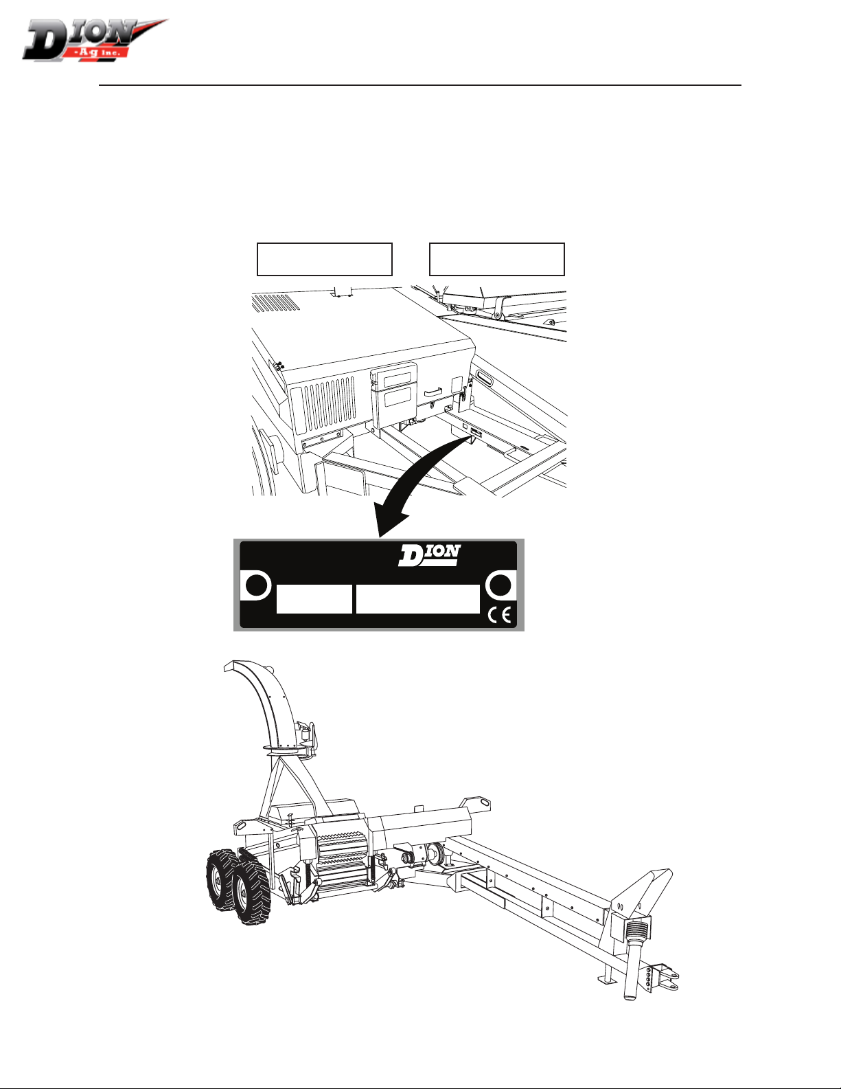
SERIAL NUMBER LOCATION
For your convenience, write down in full in this manual both the model and serial numbers of
your machine, as shown on the name plate illustrated below. Always mention both the model and
the serial numbers when ordering parts or regarding any other correspondence referring to your
machine.
Write down your number here:
MODEL NO. SERIAL NUMBER
D.F.E
BOI
.
I
SB
N
C.
RI
A
ND Q
M
ODEL
UE
.
NO.
PA
R
/
S
B
ERI
Y
DF
AL N
E
O.
M
AD
E IN CANADA
RIGHT
REAR
DION-AG INC.
BOISBRIAND QUE.
MODEL NO.
MADE IN CANADA
Dion-Ag Inc.
SERIAL NO.
LEFT
FRONT
Manual no. F4112E952 V1.2
9

PRE-SEASON CHECKS
Check condition of knives and shearbar. Check that knives and shearbar are set at zero
clearance.
Check tension of belts and chains. Make sure sheaves and sprockets are correctly
aligned.
Check all adjustable components for correct setting. Make sure adjustments are
correctly done (fan, etc)
Check tire pressure. See specications.
Check wheel rim bolt torque. See Specications.
Perform complete lubrication and servicing of the machine. Make sure all grease ttings
are in place and taking grease properly. Check gearbox and transmission uid levels.
Look for loose or missing bolts and parts.
Run the machine in a stationary position at half-speed for a short period of time.
Shut off tractor engine. Make sure all moving parts have stopped, then inspect
bearings for over-heating, excessive wear, or loose anges and lock collars.
CHECK LIST
Check metal detection system for proper operation (if installed on machine). Always
service metal detector when tractor engine is switched off.
Make sure the proper operating adjustments have been made for current crop
conditions.
Make sure SMV emblem (Slow Moving Vehicle) is in good condition and visible.
Make sure all safety shields are installed. Review Safety Precautions.
Check parts for wear (paddles, fan bottom, spout liner, etc.).
10
Manual no. F4112E952 V1.2

DAILY CHECKS
Check metal detection system. Always check metal detector system after tractor
engine has been shut off.
Remove all crop residue and wipe off oil and dirt.
Lubricate and service the machine according to the Servicing section.
Check tension of belts and chains. Check all sheaves and sprockets for correct
alignment.
Check tire pressure. See Specications.
Make sure harvester is hooked to tractor correctly, and that the safety chain is
safely installed. Make sure all controls are operable.
Sharpen knives and adjust shearbar once or twice a day.
CHECK LIST
Manual no. F4112E952 V1.2
11

FOREWORD
TO OUR CUSTOMER
The following pages and illustrations are printed to
help supply you with the knowledge to better operate and service your Dion Forage Harvester.
Any piece of equipment needs, and must have a
certain amount of service and maintenance to keep
it in top running condition. We have attempted to
cover all the adjustments required to t most conditions; however, there may be times when special
care must be taken to t a condition.
Study this operator’s manual carefully and become
acquainted with all the adjustments and operating
procedures before attempting to operate your new
equipment. Remember, it is a machine and it has
been designed and tested to do an efcient job in
most operating conditions and will perform in relation to the service it receives.
If special attention is required for some conditions,
ask your Dion Dealer; its Parts and Service department will be glad to help and answer any questions
on the operation and service of your new machine.
THIS MANUAL SHOULD REMAIN WITH THE
MACHINE WHEN SOLD
This manual was prepared from the latest product
information available at publication time. The Company reserves the right to make changes at any time
without notice.
WARRANTY INFORMATION
The warranty for this machine is located at the beginning of this manual.
If the Forage Harvester is used with an attachment
from another manufacturer, the warranty is limited to
the Forage Harvester.
You, the equipment purchaser, shall assume charges for service calls or transportation of equipment
to and from the location of servicing Dion dealer.
WARRANTY ON THE METAL DETECTOR
Because of its limitations, the metal detector cannot
and must not be expected to be a full proof device.
WARRANTY COVERAGE DOES NOT EXTEND TO
CONSEQUENTIAL DAMAGES.
SAFETY
The safety of the operator is one of the main concerns in designing and developing a new Forage
Harvester. Designers build in as many safety features as possible. However, every year accidents
occur which could have been avoided by a few seconds thought and a more careful approach to handling farm machinery and implements.
Read and implement the safety instructions detailed
in the safety section of this manual.
12
The Safety section of your Operator’s manual is intended to point out some of the basic safety situations which may be encountered during the normal
operation and maintenance of your Forage Harvester, and to suggest possible ways of dealing with
these situations. This section is NOT a replacement
for other safety practices featured in other sections
of this book.
Manual no. F4112E952 V1.2

SAFETY RULES
SAFETY ALERT SYMBOL
The symbol above calls your attention to instructions concerning your personal safety. It is found throughout the man-
ual as well as on the machine to point out specic hazards
and ways to avoid them. Always follow the instructions to
minimize the risk of personal injury or death.
DANGER, WARNING AND CAUTION
Whenever you see the words and symbols shown below,
used in this manual and on decals, you MUST take note of
their instructions as they relate to personal safety.
DANGER: This symbol together with the
word DANGER indicates an imminently hazardous situation that, if not avoided, will result in DEATH OR VERY SERIOUS INJURY.
WARNING: This symbol together with the
word WARNING indicates a potentially hazardous situation that, if not avoided, could
result in DEATH OR SERIOUS INJURY.
CAUTION: This symbol together with the
word CAUTION is used to indicate a potentially hazardous situation that, if not avoided,
may result in MINOR INJURY.
IMPORTANT: The word IMPORTANT is used to identify
special instructions or procedure which, if not strictly
observed, could result in damage to, or destruction of
the machine, process or its surroundings.
NOTE: The word NOTE is used to indicate points of particu-
lar interest for a more efcient and convenient service and
operation of the machine.
DECALS:
WARNING: DO NOT remove or obscure Danger, Warning, Caution or Instruction Decals
that are not readable or are missing. Replacement decals are available from your Dealer in
the event of loss or damage. The actual location of these Safety Decals is illustrated on
pages 17 to 21.
FOLLOW A SAFETY PROGRAM
For safe operation of a Forage Harvester, you must be a
qualied and authorized operator. To be qualied, you must
read and understand the written instructions supplied in this
Operator’s Manual, have training, and know the safety rules
and regulations for the job.
Some regulations specify that no one under the age of 16
years, for example, may operate power machinery. This includes tractors. It is your responsibility to know what these
regulations are, and obey them, in the operating area or situation.
These will include, but are not limited to, the following instructions for proper operation:
WARNING: An operator should not use alcohol or drugs which can change his alertness
or coordination. An operator on prescription
or “over the counter” drugs needs medical
advice on whether or not he or she can operate machines
A WORD TO THE OPERATOR
It is YOUR responsibility to read and understand the safety
section in this manual before operating your tractor. You must
follow these safety instructions that take you step by step
through your working day.
In reading this section, you will note that illustrations
have been used to highlight certain situations. Each
illustration is numbered and the same number appears
in the text in parenthesis.
Remember that YOU are the key to safety. Good safety practices not only protect you, but also the people around you.
Study the features in this manual and make them a working
part of your safety program.
Think SAFETY! Work SAFELY.
WARNING: In some of the illustrations used
in this Operator Instruction Book, panels or
guards may have been removed for clarity.
Never operate the machine without these
components in position. If the removal of
panels or guards is necessary to make a
repair, they MUST be replaced before operation.
Manual no. F4112E952 V1.2
13

SAFETY RULES
•
Disengage the PTO and shut off engine before
leaving the operator’s seat for refueling, lubricating or adjusting the machine.
• Always use a hitch pin large enough for the load
to be transported with a safety lock between the
tractor and the Forage Harvester and between
the Forage Harvester and the Forage Box, anytime the machine is moved.
• The tractor engine ignition key must be removed
each time the operator leaves the tractor.
• Wear appropriate clothing, safety boots or shoes.
Do not operate the machine when visibility is
bad, or during night, in poor lighting.
• When driving on a public road, or on hilly land
you must remove the electrical box ignition key
and put the locking pin in the stop pawl of the
quick-disconnect hitch to prevent unlocking. This
locking pin should also be used for the manual
quick-disconnect hitch.
• Attach a safety chain of at least 20,000 lbs (9071
Kg) capacity for transportation.
• Never hook a loaded trailer behind a Forage Har-
vester when travelling on public roads.
• Keep children away from the machine at all times.
Maximum traveling speed of a forage harvester
should not exceed 20 mph (34 km/h).
• Carefully read all safety signs applied on the machine. If they are damaged, replace them immediately.
• If a feeding or throwing mechanism should become jammed, never attempt to unblock it or
remove any material when the machine is in motion or the tractor engine running.
• Never manually feed the Forage Harvester.
• When making a metal detection test, stop the
PTO and the tractor engine, then wait until all
mobile parts are stopped.
• Never operate a Forage Harvester without rst
having installed an attachment.
• Never remove guards or make adjustments while
the machine or tractor engine is running.
• Never attempt to check or adjust chains while the
machine is running.
• Make sure all rotating parts are stopped and the
tractor engine is turned off before cleaning the
machine throat.
• Never park the Forage Harvester in its transport
position. Lower the attachment to the ground
rst.
• Before starting the tractor engine, make sure
all guards, shields, and doors are in place and
properly secured and check the machine thoroughly for possible loose parts or bolts and
tighten them.
• When knives are being readjusted, a piece of
wood should be used to immobilize the cutting
head.
• Never stand underneath the forage harvester
deector or forage path when the machine is
running. Put the discharge toward the forage
box.
• Always pick-up tools after performing any adjustment.
• Never allow riders on any part of a machine.
• Block elevated components before servicing
equipment.
• Do not unhook a farm wagon when the land is
slopping down, or service the machine without
rst blocking wheels.
• Never lubricate or clean any part while the ma-
chine or tractor engine is running.
• Keep hands and body out of hitch area when
attaching towing vehicle.
WARNING: Hydraulic uid under pressure
can penetrate the skin or eyes and cause serious personal injury, blindness or death. Fluid
leaks, under pressure, may not be visible. Use
a piece of cardboard or wood to nd leaks.
DO NOT use your bare hand. Wear gloves and
safety goggles for eye protection. If any uid is
injected into the skin, it MUST be surgically removed within a few hours by a doctor familiar
with this type of injury.
• Securely block the wheels from moving before
working on or under the machine.
• Use a lift system with a minimum capacity of
2000 lbs (900 kg) to install a Corn Attachment on
the
Forage Harvester.
• Make sure that all wheel rim bolts are properly
torqued.
• Make sure to meet local regulations for excessive
width on public roads.
14
Manual no. F4112E952 V1.2

SAFETY RULES
PTO OPERATION
• POWER-TAKE-OFF DRIVE - Before starting the
tractor engine, make sure that the PTO driveline
locking device is properly engaged onto both
the tractor and equipment drive shafts. Secure
the safety chain to the tractor frame.
• Never wear loose clothing and keep people, especially children away from the driveline.
• Do not hook a tractor with a PTO speed of 1000
RPM on a machine equipped with a 540 RPM
drive or a tractor with a PTO speed of 540 RPM
on a machine equipped with a 1000 RPM drive.
• Never proceed to the starting of the machine
before making sure all driveline, machine and
tractor shields are well installed in place
• The PTO driveline shields should turn freely, be
well connected and kept in good condition.
• Never step across any PTO driveline.
• Never use the PTO driveline as a step.
• Keep a good distance away from a rotating
driveline (approximately the distance equal to
your height).
MANDATORY STOPPING PROCEDURE
No matter what type of machine is being used, it is
extremely hazardous to perform any kind of maintenance work while the machine is running. It could
lead to serious injuries or even death. Before cleaning, adjusting or greasing the machine, the following procedure should be followed to stop the Forage
Harvester:
1. Place the transmission in neutral.
2. Disengage the tractor power-take-off (PTO).
3. Turn OFF the metal detector.
4. Switch off the tractor engine.
5. Engage the tractor parking brake.
6. Wait until all rotating parts have completely
stopped.
7. Remove the PTO from the tractor output shaft.
8. Block all equipment wheels.
WARNING: Rotating driveline contact may
cause serious injury or death.
Manual no. F4112E952 V1.2
15
SAFETY RULES
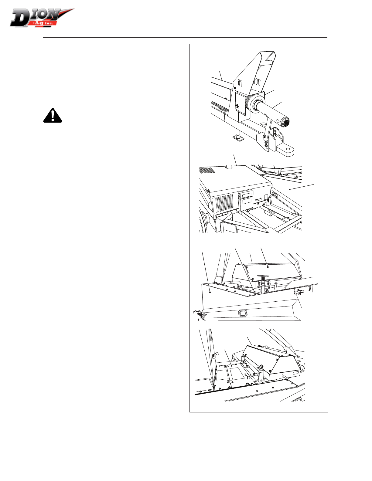
GUARDS AND SHIELDS - FIGURE 1
The Forage Harvester is equipped with guards and
shields wherever eventual accidents can occur.
These guards and shields do not keep the machine
from operating properly. Observe various safety
signs indicating these hazardous locations that are
properly applied to the machine.
CAUTION: All guards and shields factory installed should be in place and maintained in
good condition.
Item 1 A bolted guard covers the transmis-
sion shaft (on its full length) from the front
bearing up to the angle drive transmission.
Item 2 A hinged guard covers the universal joints.
Item 3 The telescopic driveline which attaches to the
tractor PTO is covered with a non-rotating
shield.
Item 4 An hinged guard covers the tool box, the
transmission shaft between the angle drive
transmission and the cutting head, the driving belts for the forward-neutral-reverse transmission and the driving system for the feeding
rolls and the attachments.
1
2
3
4
5
Item 5 An hinged guard covers the 4 blowing fan riv-
ing belts.
Item 6 An hinged guard covers the corn cracker roll
belts and the front feeding roll drive system
belts.
Item 7 An hinged guard covers the sharpening sys-
tem.
Item 8 An hinged guard covers the cutter head.
Item 9 An hinged guard covers the fan.
6
Figure 1 Guards and shields
8
7
9
7
16
Manual no. F4112E952 V1.2
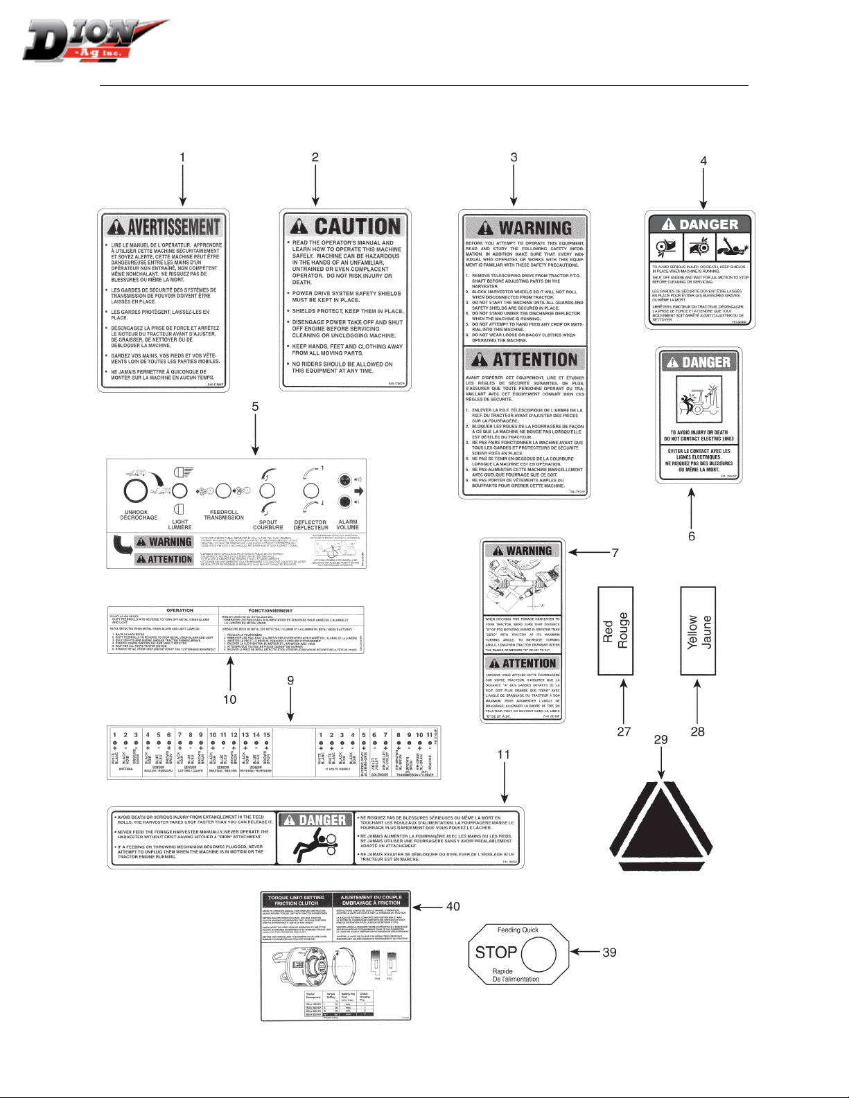
SAFETY SIGN LOCATION
IMPORTANT: Decals must be kept clean to allow easy reading at all times.
Manual no. F4112E952 V1.2
17

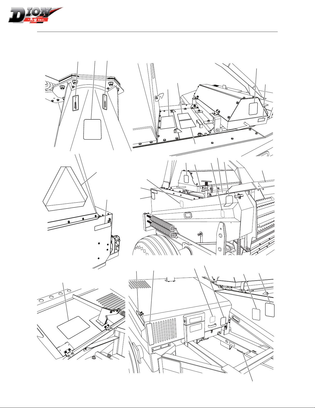
SAFETY SIGN LOCATION
IMPORTANT: Decals must be kept clean to allow easy reading at all times.
18
Manual no. F4112E952 V1.2
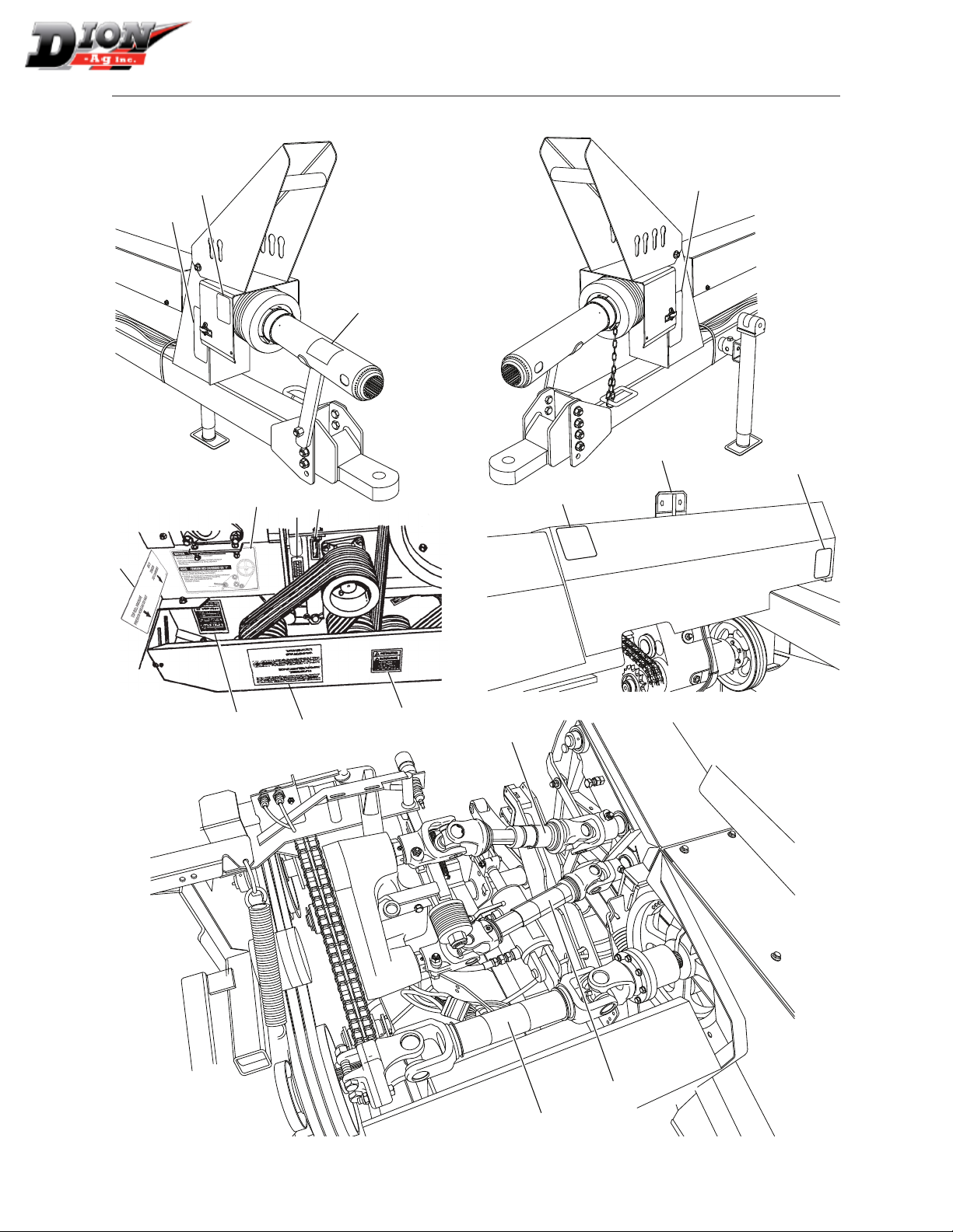
SAFETY SIGN LOCATION
IMPORTANT: Decals must be kept clean to allow easy reading at all times.
6
18
18
17
29
27
28
2
3
1
15
17
23
16
4
16
4
18
11
22
28
27
16
Manual no. F4112E952 V1.2
4
16
1000
4
30-31
19
SAFETY SIGN LOCATION
35
IMPORTANT: Decals must be kept clean to allow easy reading at all times.
14
4
12-13
24
32
8
15
7
20
4
16
26
4
12
12
20
12
Manual no. F4112E952 V1.2
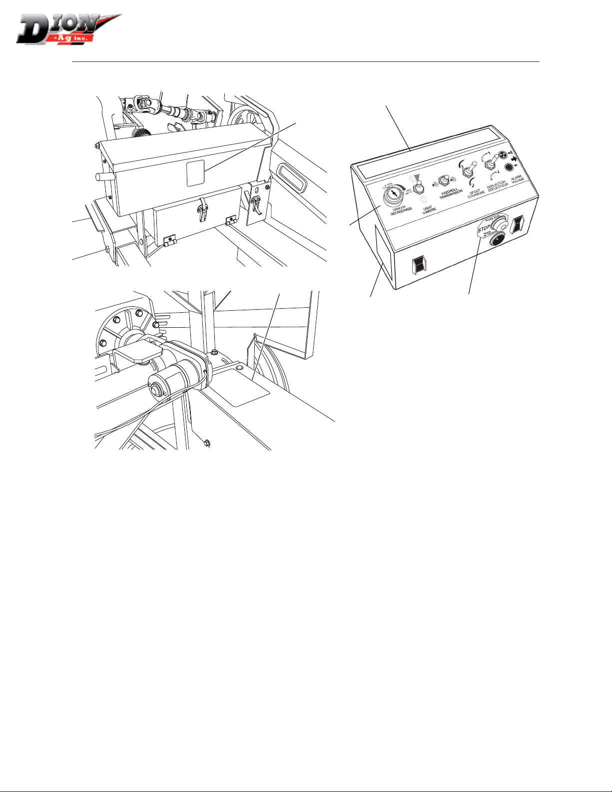
SAFETY SIGN LOCATION
IMPORTANT: Decals must be kept clean to allow easy reading at all times.
10
16
5
16
25
39
SAFETY SIGN APPLICATION PROCEDURE
1. The surface should be free from dirt, grease,
earth, or any other foreign material.
2. When the surface is dry, remove a portion of the
backing paper and apply the decal in part and
align its position as per the surrounding parts.
Slowly peel off the remaining backing paper and
apply hand pressure.
3. Press slightly on the surface of the safety sign to
remove all air bubbles.
Manual no. F4112E952 V1.2
21

DELIVERY
IMPORTANT
When signing the delivery slip, the dealer certies
having received all the equipment supplied with the
machine.
MATERIAL OR EQUIPMENT SUPPLIED WITH
THE MACHINE, PRIOR TO DELIVERY, AND INCLUDED IN THE TOOL BOX:
1 #80 - 35” (89 cm) roller chain
2 #80 connecting links
1 #80 link
1 #80 half link
1 Handle
5
12 mm X 60 mm, grade 8.8 shear bolts
2 Transport lock pin with safety pin
1 Pair of safety goggles
10 Electrical cable nylon clips
1 Sprocket - 34 teeth, for 1/2” (13 mm) cut
1 Operator’s manual
1 #60 2 1/4” (57 mm) double roller chain
1 #60 double roller chain link
1 Bar for knife adjustment
1 Pin and lock for blocking the lifting system
1 Safety chain for transport
1 Pin and lock for 4-row corn attachment
2 Pins and locks for attachments
16 5/8” dia. X 2 1/2” LG bolts + lock washers and
nuts for axle
8 5/16” X 3/4” LG bolts + nuts for lights
MATERIAL SUPPLIED SEPARATELY WITH THE
MACHINE:
1 Mounted control box
1 Control box bracket (to be bolted inside tractor
cab)
HARVESTERS ARE SHIPPED TO OPERATE AS
FOLLOWS:
• 540 or 1000 RPM Power-Take-Off (PTO) (pur-
chaser’s choice)
• Control box for the metal detector, the deector,
the spout and the transmission
• Length of cut: 3/8” (9.5 mm) and 1/2” (13 mm)
• Recuter bar attachments: factory installed
• All knife and shear bar adjustments are done at
the factory
• Built-in knife grinder
• Manual jack (gure 2)
• 240o rotation spout
OPTIONAL EQUIPMENT CHOICES:
• Metal detector (factory installed)
• Quick-disconnect hitch (manual or electrical)
• Spout light
• Work light
• Spout extensions - 12” (30 cm) or 24” (60 cm)
• Single wheels or tandem wheels
• Liquid incorporation system
• Grain pan
• Recuter bar for corn
• Corn cracker
• 60” spout horizontal extension
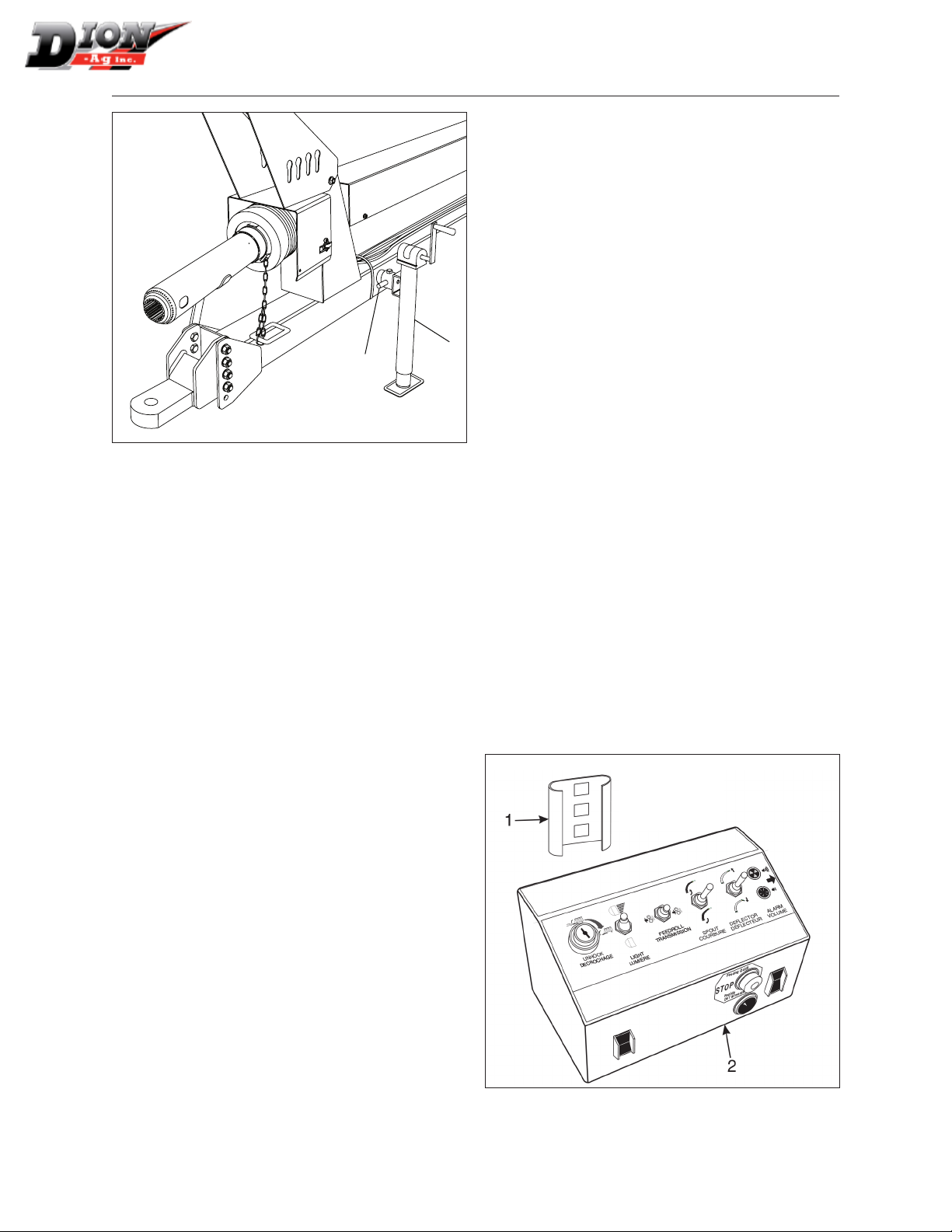
MANUAL JACK - FIGURE 2
The Forage Harvester is shipped with a manual jack
(item 1) which will support the machine when it is
unattached to the tractor. When this jack is not used,
it can be stored in its horizontal position.
CAUTION: Securely block the Forage Harvester wheels before removing the tractor
hitch pin.
22
CAUTION: Make sure the lock pin (item 2) securing the jack in its horizontal or vertical po-
sition is properly engaged through the tubes.
Manual no. F4112E952 V1.2
ASSEMBLING INSTRUCTIONS
1
2
Figure 2 Manual jack
RECEIVING YOUR FORAGE HARVESTER
Upon receiving your Forage Harvester, the following
tasks should be carried out:
• Preparing the Forage Harvester.
• Installing the wheels and lights.
• Installing the control box.
• Installing the spout.
• Connecting the power-take-off (PTO).
• Installing the spout extensions (if necessary).
• Installing the attachments (windrow pick up, or
2, 3 or 4-row crop).
• Installing the recutter bar assembly for corn (if
required).
• Installing a grain pan and a front rubber pad
assembly for corn crop (if required).
• Installing the corn cracker (if required).
• Installing a spout light (option).
• Installing an inspection light (option).
• Installing the liquid incorporation system (option).
2. Using the telescopic axle, pull the Forage Harvester’s right-hand wheel away so as to obtain a 6” (15
cm) space, which will increase its stability, and/or
that this wheel will be placed in between the corn
rows. (refer to page 96).
3. Adjust the machine’s height (refer to page 97).
4. Adjust the attachment balancing springs in order to
minimize the risks of damaging the attachment hen
there are obstacles in the eld (refer to page 100).
5. Check the metal detector system for normal opera-
tion. Follow the procedures for the daily test (refer
to page 78).
6. Check all oil levels (refer to page 87).
INSTALLING THE CONTROL BOX
FIGURES 3 AND 4
1. Install the control box support bracket (item 1) in
the tractor cab so that it is easily accessible. This
bracket is supplied with the box.
2. Install the control box (item 2) on the support
bracket. Just slide the bracket on the box inside
the support bracket.
3. Install the cable bracket (item 3) on the tractor’s
rear. Make sure it is easily accessible in order to be
readily disconnected (page 24).
4. Hook up the control box to the Forage Harvester
using the quick connects (item 4).
5. Connect the power wire (item 5) to the tractor bat-
tery. To do so, rst disconnect the tractor’s battery
negative terminal (-) to prevent any short circuit.
Must be bolted
inside tractor
cab
PREPARING THE FORAGE HARVESTER
According to the attachment being used, the following procedure should be carried out on the Forage
Harvester (please also refer to the ADJUSTMENTS
section):
1. Refer to the OPERATING INSTRUCTIONS section
for procedures on how to properly hitch the Forage
Harvester to the tractor (page 75).
Manual no. F4112E952 V1.2
Figure 3 Control box
23

ASSEMBLING INSTRUCTIONS
TO FORAGE
HARVESTER
Quick disconnect
2
5
3
4
6
TO TRACTOR
BATTERY
4
BLACK negative
WHITE positive
To tractor
(Cable bracket)
24
Figure 4 Control box wire connections
Manual no. F4112E952 V1.2
ASSEMBLING INSTRUCTIONS
NOTE: The metal detector may take as much as
45 amps to operate. It is recommended that
a wire be installed from the control box directly to the tractor battery. A weak tractor
battery should be replaced immediately.
6. Connect the black wire to the tractor frame or to
the battery’s negative (-) terminal.
7. Connect the white wire to the battery’s positive
(+) terminal.
8. Reconnect the tractor battery’s negative terminal (-).
9. Make sure all electrical connections are well
tightened and protected.
10. Make sure all electrical wires are tied up and
kept away from moving parts.
NOTE: Whenever the Forage Harvester is not in
operation, disconnect the electrical plug
(gure 4, item 4) and put back the cap (item
6) on the connector (item 3).
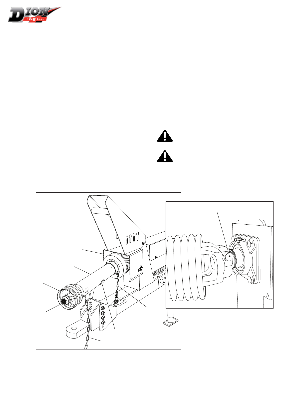
CONNECTING THE POWER-TAKE-OFF (PTO)
FIGURES 5 AND 5A
1. Couple PTO (item 1) to the Forage Harvester
with bolt (item 2) and tighten well. Connect both
halves of the PTO together, making sure to align
the two special grooves for a correct yoke alignment.
A pin placed between the two grooves allows
you to align the crosses on the PTO in order to
reduce vibration during turns.
2. Rest the PTO on its stand (item 8).
3. Attach the other safety chain (item 4) onto the
Forage Harvester frame.
CAUTION: The power-take-off (PTO) rotating shields (item 5) should turn freely on PTO
shafts.
The PTO blocking device (item 6) should be
well engaged in the tractor driving shaft slot;
then attach the safety chain (item 3) to the tractor frame.
2
7
5
1
6
4
Figure 5a Power-Take-Off (PTO)
8
3
Figure 5 Power-Take-Off (PTO)
25
Manual no. F4112E952 V1.2
ASSEMBLING INSTRUCTIONS
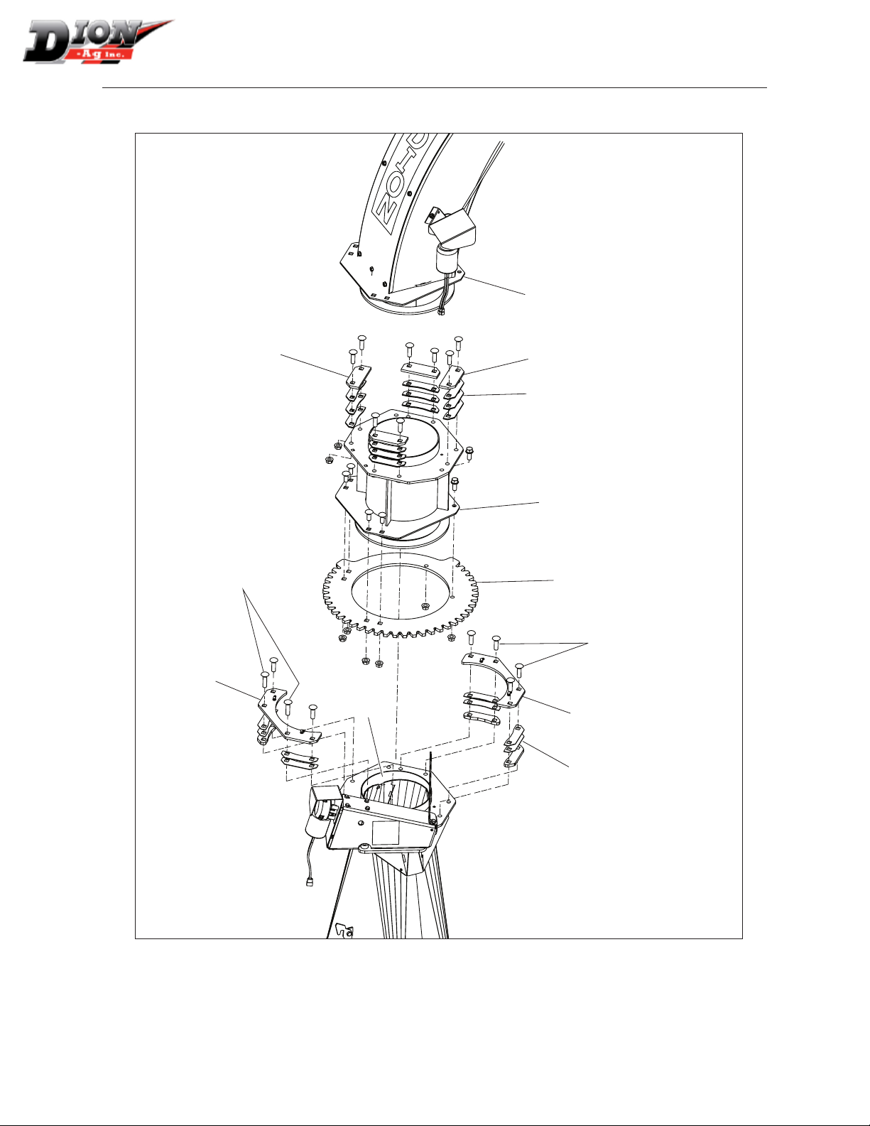
INSTALLING THE STANDARD SPOUT
FIGURE 6
1. Remove the retaining plates (tem 1) from the
outlet frame.
2. Grease the friction collar (item 2) of the outlet
frame. Smooth out the friction collar as required
at friction point on the retaining plates.
BV12X2Z (2)
1
4
3. Install the spout (item 3) with retaining plates
and shims (item 4) supplied with the spout kit.
Make sure the ring gear (item 5) is well aligned
with the rotation screw (item 6). Adjust the shim
thickness (item 4) in order to allow free rotation.
3
BV12X134Z (6)
5
4
6
Figure 6 Installing the standard spout
1
4
4
Adjust shims (items 4)
to allow free rotation
2
26
Manual no. F4112E952 V1.2
ASSEMBLING INSTRUCTIONS
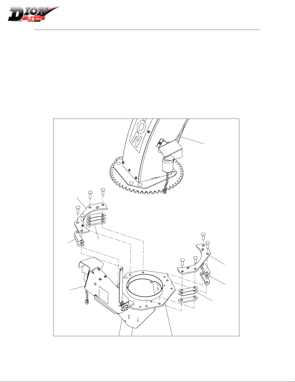
INSTALLING THE 12” (30 CM) SPOUT
EXTENSION - FIGURES 7 AND 8
1. Remove the two retaining plates (item 1) and
shims (item 4)
2. Remove the spout (item 3).
3. Unbolt the ring gear (item 5) from the spout and
transfer it to the 12” (30 cm) extension.
4. Install the 12” (30 cm) extension (item 7 in gure 8).
5. Grease the friction collar (item 2) of the outlet
frame. Smooth out the friction collar as required
at friction point on the retaining plates.
6. Install the retaining plates (item 1) and shims
(item 4). Adjust shim thickness to allow free rotation.
7. Install the spout (item 3).
8. Install the retaining plates (item 8) and shims
(item 9) supplied with the spout extension kit.
Adjust shim thickness to block rotation completely.
NOTE: The spout and the 12” (30 cm) spout exten-
sion turn together while the spout rotates
3
1
5
4
4
1
4
4
2
Figure 7 Taking apart the standard spout
Manual no. F4112E952 V1.2
27
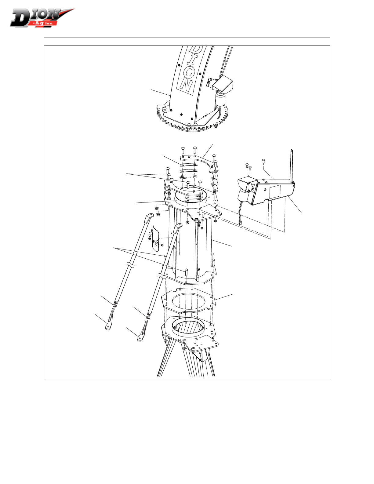
ASSEMBLING INSTRUCTIONS
3
8
2 carriage bolts
1/2” dia X 2” LG.
1
8
9
7
5
6 carriage bolts
1/2” dia X 1 3/4” LG.
2
1
28
4
Figure 8 Assembling the 12” (30 cm) spout extension
Manual no. F4112E952 V1.2
ASSEMBLING INSTRUCTIONS
INSTALLING THE 24” (60 CM) SPOUT
EXTENSION - FIGURES 9 AND 10
1. Unbolt the rotation mechanism (item 1).
2. Remove the two retaining plates (item 2) and
shims (item 4).
3. Remove the spout (item 3).
4. Install the extension spacer (item 6).
5. Install and bolt the 24” (60 cm) extension in
place (item 7). Two 1/2” X 2” lg (BH12X2Z) bolts
and six 1/2” X 1-3/4” lg bolts are required to se-
cure the extension.
6. Grease the friction collar (item 8) of the outlet
extension.
7. Install the spout (item 3).
8. Install the retaining plates (item 2) and shims
(item 4) supplied with the spout extension kit.
Adjust shim thickness to allow free rotation.
9. Reinstall the rotation mechanism (item 1).
10. Install the two adjustable reinforcement rods; one
on the left (item 9) and one on the right (item 10).
Adjust the length and lock in place with a 5/8” nut
(item 11).
3
2
4
1
4
2
4
4
Figure 9 Taking apart the standard spout
Manual no. F4112E952 V1.2
29
2 carriage bolts
1/2” dia X 2” LG.
ASSEMBLING INSTRUCTIONS
3
2
4
8
2 bolts
1/2” dia X 2” LG.
11
11
10
9
Figure 10 Assembling the 24” (60 cm) spout extension
1
7
6
30
Manual no. F4112E952 V1.2
 Loading...