

Dion Forage Blower Operator's Manual
MACHINERIES
Forage Blower
Operator's manual
Manual no. S55-03-E-885
MACHINERIES
FORAGE BLOWER
TO OUR CUSTOMER
We appreciate your confidence in DION Farm Equipment and thank you for
your trust. In preparing this manual, we hope we have furnished you with a
valuable tool for operating and maintaining this fine machine. Use this manual as your guide. Practicing the instructions given here will result in many
years of dependable service from your machine.
Your Dealer can give you assistance with parts and specially trained personnel to assist you in repair and maintenance.
Call your Dealer if you need any assistance or information.
- I -

- II -

TABLE OF CONTENTS
SPECIFICATIONS . . . . . . . . . . . . . . . . . . . . . . . . . . . . . . . . . . . . . . . . . . . . . .V
SERIAL NUMBER LOCATION . . . . . . . . . . . . . . . . . . . . . . . . . . . . . . . . . . .VII
CHECK LIST . . . . . . . . . . . . . . . . . . . . . . . . . . . . . . . . . . . . . . . . . . . . . . . . . . .VIII
FOREWORD . . . . . . . . . . . . . . . . . . . . . . . . . . . . . . . . . . . . . . . . . . . . . . . . . . .IX
SAFETY . . . . . . . . . . . . . . . . . . . . . . . . . . . . . . . . . . . . . . . . . . . . . . . . . . . . . . . . . . . . . .1
Follow a safety program . . . . . . . . . . . . . . . . . . . . . . . . . . . . . . . . . . . . . . . . . . . . . . . . . . .1
A word to the operator . . . . . . . . . . . . . . . . . . . . . . . . . . . . . . . . . . . . . . . . . . . . . . . . . . . .1
PTO operation . . . . . . . . . . . . . . . . . . . . . . . . . . . . . . . . . . . . . . . . . . . . . . . . . . . . . . . . . .2
Recommended working area . . . . . . . . . . . . . . . . . . . . . . . . . . . . . . . . . . . . . . . . . . . . . . .3
Compulsory procedures for stopping the Forage Blower . . . . . . . . . . . . . . . . . . . . . . . . . .4
Guards and shields . . . . . . . . . . . . . . . . . . . . . . . . . . . . . . . . . . . . . . . . . . . . . . . . . . . . . .4
SAFETY SIGN IDENTIFICATION . . . . . . . . . . . . . . . . . . . . . . . . . . . . . . . . . . . .5
SAFETY SIGN LOCATION . . . . . . . . . . . . . . . . . . . . . . . . . . . . . . . . . . . . . . . . . .6
SET-UP INSTRUCTIONS
Set-up instructions . . . . . . . . . . . . . . . . . . . . . . . . . . . . . . . . . . . . . . . . . . . . . . . . . . . . . . .7
1000 RPM Gearbox assembly instructions . . . . . . . . . . . . . . . . . . . . . . . . . . . . . . . . . . . .8
OPERATING INSTRUCTIONS
PTO drive shaft alignment . . . . . . . . . . . . . . . . . . . . . . . . . . . . . . . . . . . . . . . . . . . . . . . . .11
Running speed . . . . . . . . . . . . . . . . . . . . . . . . . . . . . . . . . . . . . . . . . . . . . . . . . . . . . . . . . .11
Wheel lifting system . . . . . . . . . . . . . . . . . . . . . . . . . . . . . . . . . . . . . . . . . . . . . . . . . . . . . .12
Transportating instructions without gearbox . . . . . . . . . . . . . . . . . . . . . . . . . . . . . . . . . . . .12
Transportating instructions with 1000 RPM gearbox . . . . . . . . . . . . . . . . . . . . . . . . . . . . .13
Forage Blower lifting hooks . . . . . . . . . . . . . . . . . . . . . . . . . . . . . . . . . . . . . . . . . . . . . . . .14
Maintenance door . . . . . . . . . . . . . . . . . . . . . . . . . . . . . . . . . . . . . . . . . . . . . . . . . . . . . . . .14
Water system . . . . . . . . . . . . . . . . . . . . . . . . . . . . . . . . . . . . . . . . . . . . . . . . . . . . . . . . . . .14
Speed reducer . . . . . . . . . . . . . . . . . . . . . . . . . . . . . . . . . . . . . . . . . . . . . . . . . . . . . . . . . .15
LUBRICATION
Power-Take-Off (PTO) . . . . . . . . . . . . . . . . . . . . . . . . . . . . . . . . . . . . . . . . . . . . . . . . . . . .17
Lubrication chart . . . . . . . . . . . . . . . . . . . . . . . . . . . . . . . . . . . . . . . . . . . . . . . . . . . . . . . . .17
- III -

TABLE OF CONTENTS
ADJUSTMENTS - MAINTENANCE
Rotating outlet . . . . . . . . . . . . . . . . . . . . . . . . . . . . . . . . . . . . . . . . . . . . . . . . . . . . . . . . . .21
Fan adjustment . . . . . . . . . . . . . . . . . . . . . . . . . . . . . . . . . . . . . . . . . . . . . . . . . . . . . . . . . .21
PTO shear bolts . . . . . . . . . . . . . . . . . . . . . . . . . . . . . . . . . . . . . . . . . . . . . . . . . . . . . . . . .23
Auger screw replacement . . . . . . . . . . . . . . . . . . . . . . . . . . . . . . . . . . . . . . . . . . . . . . . . . .23
Auger screw adjustment . . . . . . . . . . . . . . . . . . . . . . . . . . . . . . . . . . . . . . . . . . . . . . . . . . .23
Auger screw intermediate belt tension . . . . . . . . . . . . . . . . . . . . . . . . . . . . . . . . . . . . . . . .24
Auger screw drive belt tension . . . . . . . . . . . . . . . . . . . . . . . . . . . . . . . . . . . . . . . . . . . . . .24
Auger belt replacement . . . . . . . . . . . . . . . . . . . . . . . . . . . . . . . . . . . . . . . . . . . . . . . . . . .25
Auger screw brake . . . . . . . . . . . . . . . . . . . . . . . . . . . . . . . . . . . . . . . . . . . . . . . . . . . . . . .25
Air intake control . . . . . . . . . . . . . . . . . . . . . . . . . . . . . . . . . . . . . . . . . . . . . . . . . . . . . . . . .25
Suggested initial air intake adjustments . . . . . . . . . . . . . . . . . . . . . . . . . . . . . . . . . . . . . . .26
Dismantling and reassembly of PTO rotating guards . . . . . . . . . . . . . . . . . . . . . . . . . . . . .26
Eccentric locking collar installation . . . . . . . . . . . . . . . . . . . . . . . . . . . . . . . . . . . . . . . . . . .26
Reminder . . . . . . . . . . . . . . . . . . . . . . . . . . . . . . . . . . . . . . . . . . . . . . . . . . . . . . . . . . . . . .26
Speed reducer . . . . . . . . . . . . . . . . . . . . . . . . . . . . . . . . . . . . . . . . . . . . . . . . . . . . . . . . . .27
Chain tension check . . . . . . . . . . . . . . . . . . . . . . . . . . . . . . . . . . . . . . . . . . . . . . . . . . . . . .27
Chain adjustment . . . . . . . . . . . . . . . . . . . . . . . . . . . . . . . . . . . . . . . . . . . . . . . . . . . . . . . .27
Alignment and adjustment of the speed reducer . . . . . . . . . . . . . . . . . . . . . . . . . . . . . . . .28
Storage . . . . . . . . . . . . . . . . . . . . . . . . . . . . . . . . . . . . . . . . . . . . . . . . . . . . . . . . . . . . . . . .29
TROUBLESHOOTING . . . . . . . . . . . . . . . . . . . . . . . . . . . . . . . . . . . . . . . . . . . . . . . .31
- IV -

SPECIFICATIONS
(Specifications and design are subject to change without notice and without liability there-
fore.)
MAIN FAN
Main fan . . . . . . . . . . . . . . . . . . . . . . . . . . . . . . . . . . . . . 59” (150cm)
Blades . . . . . . . . . . . . . . . . . . . . . . . . . . . . . . . . . . . . . . . 8
RPM . . . . . . . . . . . . . . . . . . . . . . . . . . . . . . . . . . . . . . . . 540
RPM (with reducer) . . . . . . . . . . . . . . . . . . . . . . . . . . . . . 650
Speed at blade tip:
540 RPM . . . . . . . . . . . . . . . . . . . . . . . . . . . . . . . . . . . . . 8340 ft/min. (2542m/min)
650 RPM . . . . . . . . . . . . . . . . . . . . . . . . . . . . . . . . . . . . . 10038 ft/min. (3060m/min)
MAIN AUGER
Length . . . . . . . . . . . . . . . . . . . . . . . . . . . . . . . . . . . . . . . 55” (140cm)
Diameter . . . . . . . . . . . . . . . . . . . . . . . . . . . . . . . . . . . . . 14” (36cm)
Pitch . . . . . . . . . . . . . . . . . . . . . . . . . . . . . . . . . . . . . . . . 10” (25cm)
RPM . . . . . . . . . . . . . . . . . . . . . . . . . . . . . . . . . . . . . . . . 500
RPM(with reducer) . . . . . . . . . . . . . . . . . . . . . . . . . . . . . 601
Overall length with pole . . . . . . . . . . . . . . . . . . . . . . . . . . 129” (378cm)
Overall width . . . . . . . . . . . . . . . . . . . . . . . . . . . . . . . . . . 84” (213cm)
DRUM OUTLET HEIGHT
Transportation position . . . . . . . . . . . . . . . . . . . . . . . . . . 70” (178cm)
Operating position (wheels lowered) . . . . . . . . . . . . .. . . . 61” (155cm)
HOPPER
Height (operating position) . . . . . . . . . . . . . . . . . . . . . . . 21” (53cm)
Inlet width . . . . . . . . . . . . . . . . . . . . . . . . . . . . . . . . . . . . 42” (107cm)
Inlet depth . . . . . . . . . . . . . . . . . . . . . . . . . . . . . . . . . . . . 30” (76cm)
Tires . . . . . . . . . . . . . . . . . . . . . . . . . . . . . . . . . . . . . . . . 16.5 X 6,5-8
Weight . . . . . . . . . . . . . . . . . . . . . . . . . . . . . . . . . . . . . . . 1350 lbs (610Kg)
- V -

- VI -
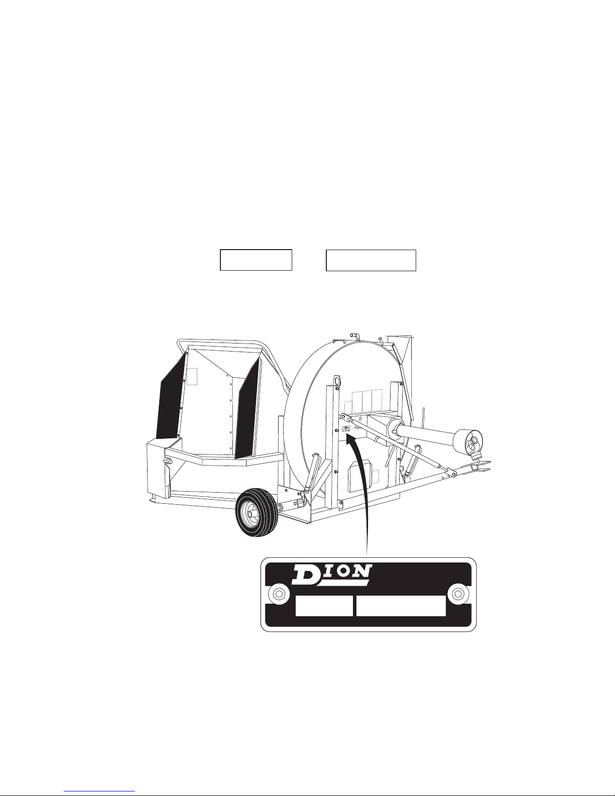
SERIAL NUMBER
LEFT
RIGHT
FRONT
REAR
MACHINERIES
AB - 0123 456789
MODEL NO.
SERIAL NO.
MADE IN CANADA
BOISBRIAND, QUÉ.
LOCATION
For your convenience, write down in full in this manual both the model and
serial numbers of your machine, as shown on the name plate illustrated
below. Always mention both the model and the serial numbers when ordering parts or regarding any other correspondence referring to your machine
Write down your number here:
MODEL NO.
SERIAL NUMBER
- VII -

PRE-SEASON CHECKS
Check auger screw brake.
Check tension of belts. Check all sheaves for correct alignment.
Check all adjustable components for correct setting (blower and auger).
Check tire pressure. See specifications.
Perform complete lubrication and servicing of the machine according to Servicing.
Make sure all grease fittings are in place and taking grease properly. Check gearbox
fluid levels if you have the option.
Look for loose or missing bolts and parts.
Run the machine in a stationary position at half-speed for a short period of time.
Shut off tractor engine. Make sure all moving parts have stopped, then inspect
bearings for over-heating, excessive wear, or loose flanges and lock collars.
Make sure the proper operating adjustments have been made.
Make sure all safety shields are installed. Review Safety Precautions.
CHECK LIST
Check for wear on parts (paddles, blower and auger bottoms, etc.).
DAILY CHECKS
Check auger screw brake
Remove all crop residue and wipe off oil and dirt.
Lubricate and service the machine according to the Servicing section.
Check belt tension. Check all sheaves for correct alignment.
Check tire pressure. See Specifications.
Make sure Blower is hooked to tractor correctly, and that the safety chain is
installed securely. Make sure all controls are operable.
Make sure that all safety shields are in good condition on the blower (with a special
attention on the PTO shields).
- VIII -

FOREWORD
TO OUR CUSTOMER
The following pages and illustrations are printed
to help supply you with the knowledge to better
operate and service your DION Forage Blower.
Any piece of equipment needs, and must have a
certain amount of service and maintenance to
keep it in top running condition. We have
attempted to cover all the adjustments required
to fit most conditions; however, there may be
times when special care must be taken to fit a
condition.
Study this operator’s manual carefully and
become acquainted with all the adjustments and
operating procedures before attempting to operate your new equipment. Remember, it is a
machine and it has been designed and tested to
do an efficient job in most operating conditions
and will perform in relation to the service it
receives.
If special attention is required for some conditions, ask your DION Dealer; his parts and
Service Organization will be glad to help and
answer any questions on operation and service
of your new machine.
WARRANTY INFORMATION
Your DION Warranty for this machine appears on
your copy of the Retail Purchase Order and
Warranty Terms and Conditions Statement which
you received from your dealer when you purchased the Blower.
As indicated on the Retail Purchase Order signed
by you and your dealer, you, the equipment purchaser, shall assume charges for service calls or
transportation of equipment to and from the location of servicing DION dealer.
SAFETY
The safety of the operator is one of the main concerns in designing and developing a new Forage
Blower. Designers build in as many safety features as possible. However, every year many
accidents occur which could have been avoided
by a few seconds thought and a more careful
approach to handling farm machinery and implements.
Read and implement the safety instructions
detailed in the safety section of this manual.
THIS MANUAL SHOULD REMAIN WITH THE
MACHINE WHEN SOLD
This manual was prepared from the latest product information available at publication time. The
Company reserves the right to make changes at
any time without notice.
The safety section of your Operator’s manual is
intended to point out some of the basic safety situations which may be encountered during the
normal operation and maintenance of your
Forage Blower, and to suggest possible ways of
dealing with these situations. This section is NOT
a replacement for other safety practices featured
in other sections of this book.
- IX -

- X -
SAFETY
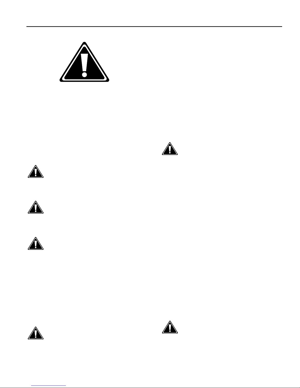
SAFETY ALERT SYMBOL
The symbol above calls your attention to instructions
concerning your personal safety. It is found throughout
the manual as well as on the machine to point out specific hazards and ways to avoid them. Always follow the
instructions to minimize the risk of personal injury or
death.
DANGER, WARNING AND CAUTION
Whenever you see the words and symbols shown
below, used in this manual and on decals, you MUST
take note of their instructions as they relate to personal
safety.
DANGER: This symbol together with the
word DANGER indicates an imminently
hazardous situation that, if not avoided,
will result in DEATH OR VERY SERIOUS
INJURY.
FOLLOW A SAFETY PROGRAM
For safe operation
For safe operation of a Forage Blower, you must be a
qualified and authorized operator. To be qualified, you
must read and understand the written instructions supplied in this Operator’s Manual, have training, and know
the safety rules and regulations for the job.
Some regulations specify that no one under the age of
16 years, for example, may operate power machinery.
This includes tractors. It is your responsibility to know
what these regulations are, and obey them, in the operating area or situation.
These will include, but are not limited to, the following
instructions for proper operation.
WARNING: An operator should not use
alcohol or drugs which can change his
alertness or co-ordination. An operator on
prescription or “over the counter” drugs
needs medical advice on whether or not he
or she can operate machines.
A WORD TO THE OPERATOR
WARNING: This symbol together with
the word WARNING indicates a potentially
hazardous situation that, if not avoided,
could result in DEATH OR SERIOUS
INJURY.
CAUTION: This symbol together with
the word CAUTION is used to indicate a
potentially hazardous situation that, if not
avoided, may result in MINOR INJURY.
IMPORTANT: The word IMPORTANT is used to identify special instructions or procedure which, if not strictly
observed, could result in damage to, or destruction of
the machine, process or its surroundings.
NOTE: The word NOTE is used to indicate points of
particular interest for more efficient and convenient
repair or operation.
DECALS
WARNING: DO NOT remove or obscure
Danger, Warning, Caution or Instruction
decals that are not readable or are missing.
Replacement decals are available from
your Dealer in the event of loss or damage.
The actual location of these Safety Decals
is illustrated on pages 6.
It is YOUR responsibility to read and understand the
safety section in this manual before operating your
machine. You must follow these safety instructions that
take you step by step through your working day.
In reading this section, you will note that illustrations
have been used to highlight certain situations. Each
illustration is numbered and the same number appears
in the text in parenthesis. This number is placed at the
end of the written text that refers to the illustration.
Remember that YOU are the key to safety. Good safety practices not only protect you, but also the people
around you. Study the features in this manual and
make them a working part of your safety program.
Keep in mind that this safety section is written only for
this type of machine. Practice all other usual and customary safe working precautions, and above all.
REMEMBER - SAFETY IS YOUR RESPONSIBILITY.
YOU CAN PREVENT SERIOUS INJURY OR DEATH.
WARNING: In some of the illustrations
used in this Operator Instruction Book,
panels or guards may have been removed
for clarity. Never operate the machine
without these components in position. If
the removal of panels or guards is necessary to make a repair, they MUST be
replaced before operation.
Page 1

SAFETY
Wear appropriate clothing, safety boots or shoes. Do
not operate the machine when visibility is bad, or during night, in poor lighting.
Keep children away from the machine at all times.
Carefully read all safety signs applied on the machine.
If they are damaged, replace them immediately.
Keep hands and clothes away from all moving parts.
Never lubricate or clean any part while the machine or
tractor engine is running.
If a feeding or throwing mechanism should become
jammed, never attempt to unblock it or remove any
material when the machine is in motion or the tractor
engine running.
Never remove guards or make adjustments while the
machine or tractor engine is running.
Before starting the tractor engine, make sure all
guards, shields, and doors are in place and properly
secured and check the machine thoroughly for possible
loose parts or bolts and tighten them.
Be very careful when adjusting the fan blades and hopper auger screw.
PTO OPERATION
POWER-TAKE-OFF DRIVE - Before starting the tractor
engine make sure that the PTO driveline locking device
is properly engaged onto both the tractor and equipment drive shafts.
Never wear loose clothing and keep people, especially
children away from the driveline.
Do not hook a tractor witha PTO speed of 1000 RPM on
a machine equipped with a 540 RPM drive and/or a
tractor with a driveline speed of 540 RPM on a machine
equipped with a 1000 RPM drive.
Never proceed to the starting of the machine before
making sure all PTO, machine and tractor shields are
well installed in place.
The PTO driveline shields should turn freely, be well
connected and kept in good condition.
Never step across any PTO driveline.
Never use the PTO driveline as a step.
Keep at least your height away from a rotating driveline.
Before operating make sure that all projection pipes are
properly fastened.
Keep hands and feet out of hopper when the PTO is
coupled to the tractor and the tractor engine is running.
Do not climb over or around the hopper when the forage blower is in operation.
If it is necessary to enter a silo, make sure it is well ventilated.
Always keep the forage blower hitch pinned to tractor
draw bar when operating.
Make sure all rotating parts are stopped and the tractor
engine is turned off before cleaning or servicing fan and
conduct.
After having performed any adjustments, be sure that
there are no tools in or on the machine.
Page 2
 Loading...