

Dioluce DL-R24-4530-4K0-001, DL-R24-5035-5K0-001, DL-R24-4530-4K0-002, DL-R24-5035-4K0-001, DL-R24-5035-4K0-002 Installation Instructions Manual
...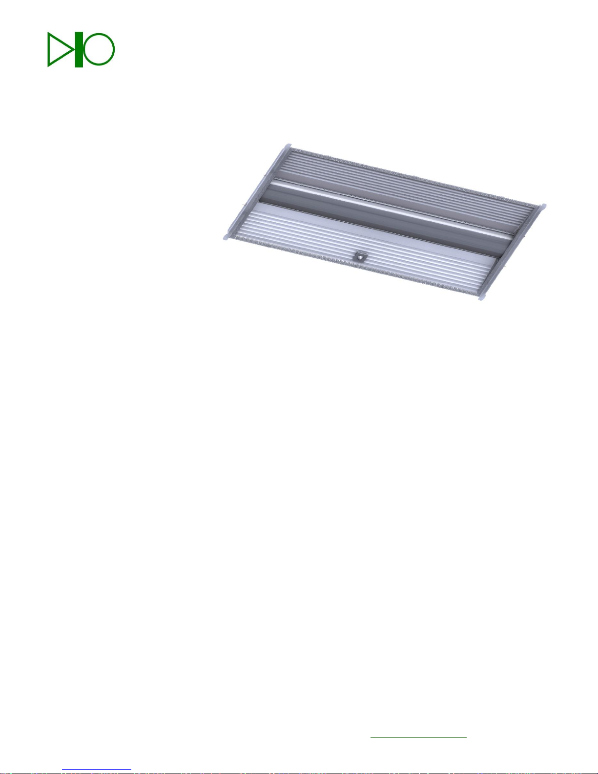
Dioluce Products Installation Instructions
Models
DL-R24-4530-5K0-001
DL-R24-4530-5K0-002
DL-R24-5035-5K0-001
DL-R24-5035-5K0-002
DL-R24-4530-4K0-001
DL-R24-4530-4K0-002
DL-R24-5035-4K0-001
DL-R24-5035-4K0-002
Important
Read all instructions carefully before attempting installation. Failure to follow all
instructions may result in electrical shock, fire and/or injury. If you do not
understand these instructions, please contact your local distributor.
Inspect the components for any damage; damage should be reported to your
distributor.
Safety
Refer to facility and site safety regulations before performing any work presented
in this manual to ensure personnel safety.
All electrical connections must be in accordance with the National Electric
Code and local codes or ordinances.
All work should be performed by a licensed electrician.
This fixture must be mounted into an approved, four foot, recessed light fixture
that is directly supported by the building structure.
Take note of installation location. Do not install in a damp, wet location, or next
to leaking pipes or equipment. This environment can cause shock or
electrocution.
DioLuce, LLC 185 Main St. #4230300 New Britain, CT 06051 www.dioluce.com 1

Warnings
1. Do not connect DioLuce LED components to any other
manufacturers power supply or LED components. Risk
of electrical shock or fire.
2. Verify incoming voltage matches the voltage rating on
the power supply, 120 VAC or 277 VAC.
3. Do not connect any DioLuce components to fluorescent
lamp ballast. Risk of electrical shock or fire.
4. Risk of fire or electrical shock. Luminaire wiring and
electrical parts may be damaged when drilling for
installation of LED retrofit kit. Check for enclosed
wiring and components.
5. Risk of fire and electrical shock. LED Retrofit Kit
installation requires knowledge of luminaires electrical
systems. If not qualified, do not attempt installation.
Contact a qualified electrician.
6. Risk of fire or electrical shock. Install this kit only in
luminaires that have the construction features and
dimensions shown in the drawings and where the input
rating of the retrofit kit does not exceed the input rating
of the luminaire.
7. To prevent wiring damage or abrasion, do not expose
wiring to edges of sheet metal or other sharp objects.
DioLuce, LLC 185 Main St. #4230300 New Britain, CT 06051 www.dioluce.com 2
SW1
SW2
SW3
Mode
Power Watts
Mode/Standby
1 0 0
Day Light
40/20
0 1 0
Day Light
35/20
0 0 1
Day Light
30/20
1 1 0
Motion
Detector
40/20
0 1 1
Motion
Detector
35/20
1 0 1
Motion
Detector
30/20
0 0 0
Low
20
1 1 1
High
40
Day Light
Day Light Sensor activated, switches to lower power
Motion Detector
Motion Sensor activated, switches to higher power
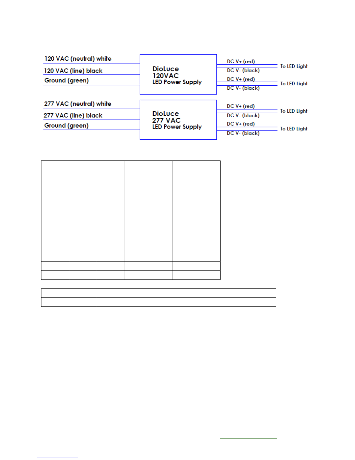
Electrical Connection Wiring Diagram
Dip Switch Configuration
DioLuce, LLC 185 Main St. #4230300 New Britain, CT 06051 www.dioluce.com 3
 Loading...