

Diodes ZXRE125 User Manual
A
Product Line o
f
Diodes Incorporated
ZXRE125
SOT23 MICROPOWER 1.22V VOLTAGE REFERENCE
Description
The ZXRE125 is a bandgap circuit designed to achieve a
precision micropower voltage reference of 1.22 volts. The
device is available in the small outline SOT 23 surface mount
package which is ideal for applications where spac e saving
is important.
SOT23 tolerance is available to 0.5% for precision
applications. Excellent performance is maintained over the
8µA to 20mA operating current range with a typical
temperature coefficient of only 20ppm/°C. The device has
been designed to be highly tolerant of capacitive loads so
maintaining excellent stability.
This device offers a SOT23 pin for pin compatible
replacement of the ZRA124 and ZRA125 series of voltage
references.
Features
• High performance 1.220V reference
• Small outline SOT23
• 4μA knee current
• 20ppm/°C typical temperature coefficient
• Unconditionally stable
• 0.5%, 1%, 2%, and 3% tolerance
• Green molding compound (No Br, Sb)
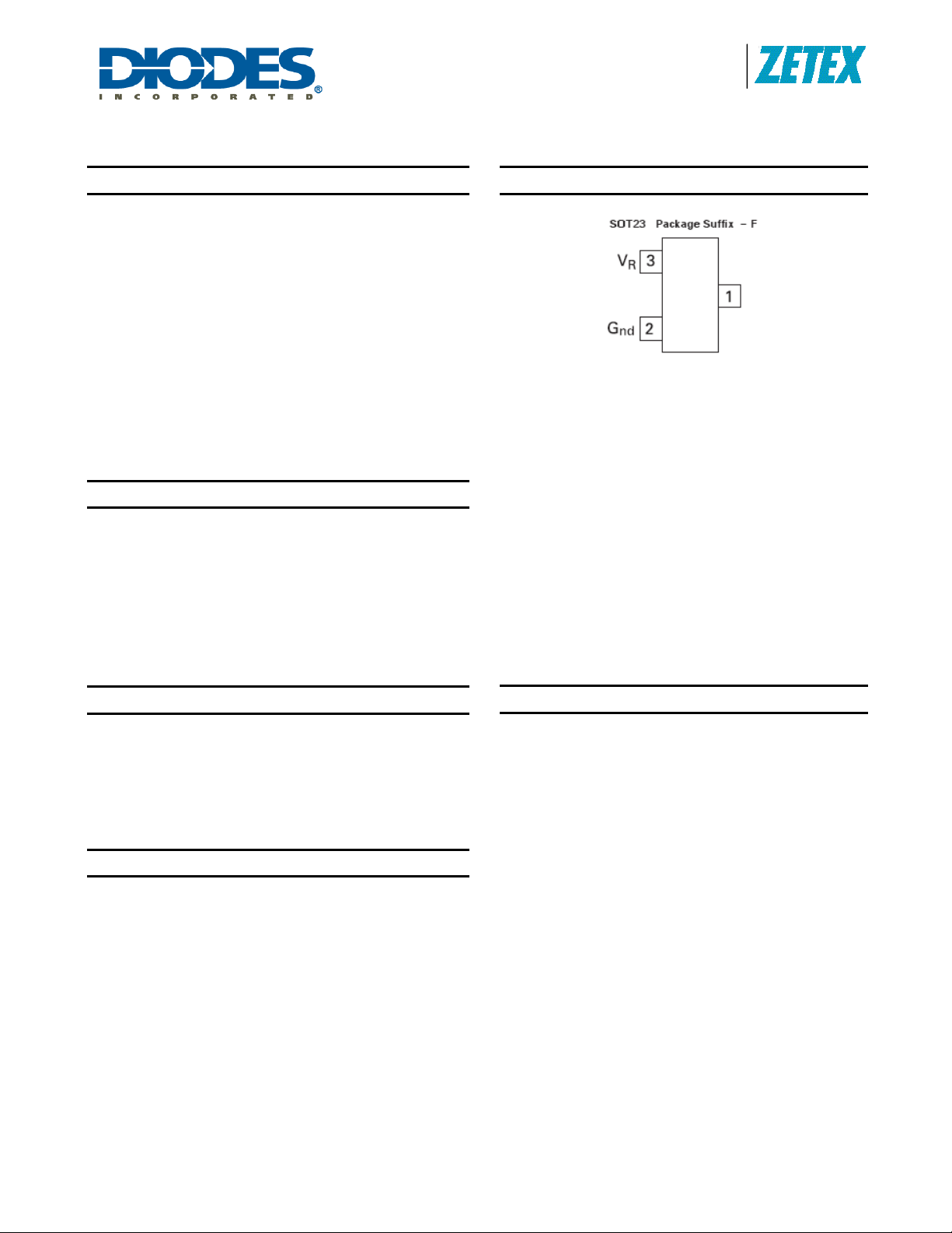
Pin Assignments
Pin 1 floating or connected to pin 2
OBSOLETE
(Bottom View)
Pin 3 floating or connected to pin 1
(Top View)
Applications
• Battery powered equipment
• Precision power supplies
• Portable instrumentation
• Portable communication devices
• Data acquisition systems
Schematic Diagram
Application Circuit
ZXRE125
Document number: DS32170 Rev. 8 - 2
1 of 5
www.diodes.com
June 2010
© Diodes Incorporated
A
Product Line o
f
(1)
)
)
(
)
(
)
Diodes Incorporated
ZXRE125
Absolute Maximum Ratings (Voltages to GND Unless Otherwise Stated)
Parameter Symbol Rating Unit
Reverse Current VZ 30 mA
Forward Current 10 mA
Operating Temperature T
Storage Temperature T
Power Dissipation (T
AMB
= 25°C)
-40 to 85 °C
OMP
-55 to 125 °C
STG
PD 330 mW
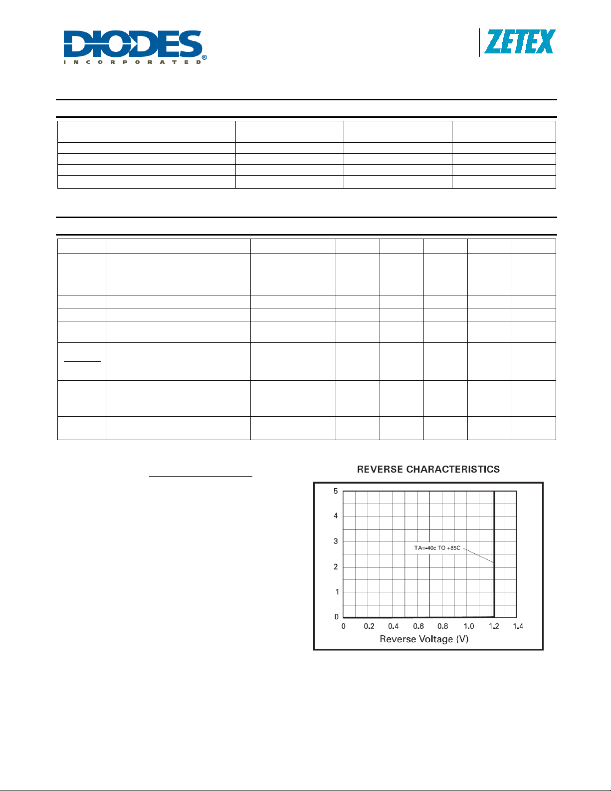
Electrical Characteristics (Test conditions: T
= 25°C, unless otherwise specified.)
amb
Symbol Parameter Condition Min. Typ. Max. Tol. (%) Unit
VR
I
MIN
IR
T
1.214
Reverse breakdown voltage
IR = 100µA
1.208
1.196
1.183
Minimum operating current 4 8
Recommended operating current 0.008 20
(*)
C
Average reverse breakdown
voltage temperature coefficient
I
R(min)
to I
20 75
R(max)
1.220
1.220
1.220
1.220
1.226
1.232
1.244
1.257
C/0.5
D/1
E/2
F/3
V
µA
mA
ppm/°C
ZR
ΔVR
ΔI
Reverse Breakdown Change
with Current Voltage
R
Reverse dynamic impedance
= 30μA to 1mA
I
R
I
= 1mA to 12mA
R
IR = 1mA
f = 100Hz
1
10
0.2 0.6
mV
Ω
IAC = 0.1IR
EN
Notes:
Wideband noise voltage
= 8µA to 100µA
I
R
f = 10Hz to 10kHz
60
µV(rms)
1.
(*)
TC =
(V
R(MAX
V
R
– V
x (T
R(MIN
MAX
– T
) x 1000000
)
MIN
Note: V
voltage measured over the full operating temperature range.
ZXRE125
Document number: DS32170 Rev. 8 - 2
R(MAX)
- V
is the maximum deviation in reference
R(MIN)
2 of 5
www.diodes.com
June 2010
© Diodes Incorporated
 Loading...