

Diodes ZXLD1370 EV4, ZXLD1371 EV4 User Manual
ZXLD1370/1EV4 User Guide
1.5A 40W Buck-Boost LED Driver
Parameter
Value
Input Voltage
10 to 30VDC (1371)
10 to 20VDC (1370)
Output Power
30 – 40W
LED Current
1.5A (Adjustable)
LED Voltage
27V
Efficiency
~85%
Number of LEDs
9 LEDs in series
(Under Tested)
XYZ Dimension
3.00 ” x 3.25” x 0.5”
ROHS Compliance
Yes
DC-
DC+
LED+
LED-
General Description
The ZXLD1370/1 EV4 1.5A board uses the Buck-
Boost topology working at Boundary
Conduction Mode. It can perform step-down or
boost up power conversion according to the
output LEDs load vs. input voltage. It is designed
for driving a high LED current from a wide range
voltage source. The board can operate from an
input supply between 10V and 30V and
provides an externally adjustable output
current of up to 1.5A. The ZXLD1370/1 EV4
board can provide more than 40 watts of
output power.
Key Features
Wide input voltage range: 10V to 30V
Up to 1.5A output current
Single pin on/off and brightness control
using DC voltage or PWM
Up to 1MHz switching frequency
±5% output current accuracy
Inherent open-circuit LED protection
High-Side Current Sense
Hysteretic Control: No Compensation
Adjustable output LED Current
TSSOP-16EP package for large output power
application
RoHS compliant
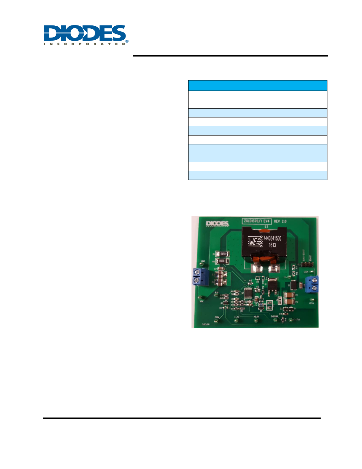
ZXLD1370/1 EV4 Specifications
Evaluation Board
Applications
High lumen LED Bulb
Automotive high power LED lamp
ZXLD1370/1EV4 Rev2 Page 1 of 11
October 2016
www.diodes.com
Figure 1: Top View
Connection Instructions
Input Voltage: 10 to 30VDC (DC+, DC-)
LED Outputs: LED+ (Red), LED- (Black)
ZXLD1370/1EV4 User Guide
1.5A 40W Buck-Boost LED Driver
R sense circuit
Buck-Boost inductor
ZXLD1370 or 1371
BCM driver
MOSFET Driver
+ Low side MOSFET
9 LEDs
10V~30V
DC Input
Input DC
Filter
ZXLD1370
or ZXLD1371
Board
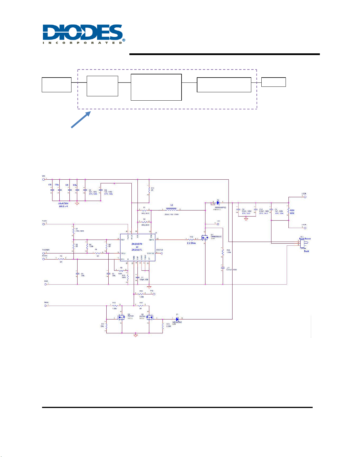
Figure 2: Block Diagram
Evaluation Board Schematic
Figure 3: Evaluation Board Schematic
ZXLD1370/1EV4 Rev2 Page 2 of 11
October 2016
www.diodes.com

ZXLD1370/1EV4 User Guide
1.5A 40W Buck-Boost LED Driver
#
Name
Quantity
Part number
Manufacturer
Description
1
U1
1
ZXLD1370EST16TC or
ZXLD1371EST16TC
Diodes Inc
LED Driver TSSOP16L
2
U2 0 Not fitted
3
Q1 1 DMN6068LK3
Diodes Inc
MOSFET 60V/8.5A DPAK
4
Q2 1 2N7002
Diodes Inc
MOSFET 60V/115mA SOT23
5
Q3 0 Not fitted
6
D1 1 PDS3100
Diodes Inc
Freewheeling diode 100V/3A
PowerDI5
Evaluation Board Layout
Figure 4: PCB Board Layout Top View
Figure 5: PCB Board Layout Bottom View
Quick Start Guide
1. By default, the evaluation board is preset at 1.5A LED current by R1 & R2.
2. Ensure that the DC source is switched OFF or disconnected.
3. Connect the 15V
power supply to two test points of “DC input” on the left side of the
DC
board.
4. Connect the anode wire of external LED string to LED+ output test point.
5. Connect the cathode wire of external LED string to LED- output test point.
6. Turn on the main switch. LED string should light up.
Bill of Material
ZXLD1370/1EV4 Rev2 Page 3 of 11
October 2016
www.diodes.com

ZXLD1370/1EV4 User Guide
1.5A 40W Buck-Boost LED Driver
7
D2 0 Not fitted
8
D3 0 Not fitted
9
Z1 1 BZX84B39
Diodes Inc
39V 350mW Zener Diode SOT23
10
L1 1 7443641500
Wurth
15µH/30A SMD
28.5x19.5x18.5mm
11
C1 1 C0805C102K3RACTU
Kemet
1000pF Cer Cap 25V 10% X7R
0805
12
C2 2 C1206C104K5RAC7867
Kemet
1µF Cer Cap 50V 10% X7R 1206
13
C3, C3A,
C4, C4A
4
C1812X106K050T
Holy Stone
10µF Cer Cap 50V 10% X7R 1812
14
C5 2 GRM31CR72A105KA01L
Murata
1µF Cer Cap 100V 10% X7R 1206
15
C6 1 GRM21BR61E106KA73L
Murata
10µF Cer Cap 25V 10% X5R 0805
16
C7 1 C0805C104K5RACTU
Kemet
0.1µF Cer Cap 50V 10% X7R 0805
17
C8 1 C1206X475K050T
Holy Stone
4.7µF Cer Cap 35V 10% X7R 1206
18
C9, C10
2
C1812X225K050T
Holy Stone
2.2µF Cer Cap 50V 10% X7R 1812
19
C11 0 Not fitted
20
R1 1 RLP73K3AR15JTE
TE Connectivity
0.15Ω Resistor 2W 1% 2512
21
R2 2 RLP73K3AR30JTE
TE Connectivity
0.30Ω Resistor 2W 1% 2512
22
R3, R5,
R6, R8,
R11, R14
6
CRCW08050000Z0EA
Vishay
0 Ω Resistor 1/8W 0805
23
R4
1
RC0805FR-071K3L
Yageo
1.3kΩ Resistor 1/8W 1% 0805
24
R7
1
RC0805FR-0747KL
Yageo
47kΩ Resistor 1/8W 1% 0805
25
R9, R10
2
RC0805FR-0736KL
Yageo
36kΩ Resistor 1/8W 1% 0805
26
R12 1 RC0805FR-072R2L
Yageo
2.2Ω Resistor 1/8W 1% 0805
27
R13 1 RC0805FR-075R11L
Yageo
5.1Ω Resistor 1/8W 1% 0805
28
R15, R17
2
RC0805FR-0720KL
Yageo
20kΩ Resistor 1/8W 1% 0805
29
R16, R18,
R19 3 RC0805FR-071KL
Yageo
1kΩ Resistor 1/8W 1% 0805
30
R20 1 RC0805FR-0782KL
Yageo
82kΩ Resistor 1/8W 1% 0805
31
J1 1 1776244-2
TE Connectivity
TERM BLOCK 2POS SIDE ENTRY
5MM
32
PL1 1 800-10-003-10-001000
Mill-Max
SIP HEADER 3 POS
33
Vin, GND,
PWM,
TP1,
LEDA,
LEDK
6
5121K-ND
Keystone
Test point
ZXLD1370/1EV4 Rev2 Page 4 of 11
October 2016
www.diodes.com
 Loading...