

Diodes ZVP4424Z User Manual

A
f
D
Product Line o
Diodes Incorporated
ZVP4424Z
240V P-CHANNEL ENHANCEMENT MODE VERTICAL DMOS FET
Features
• BV
• R
• Low threshold and Fast switching
• Totally Lead-Free & Fully RoHS compliant (Notes 1 & 2)
• Halogen and Antimony Free. “Green” Device (Note 3)
• Qualified to AEC-Q101 Standards for High Reliability
• PPAP capable (Note 4)
> -240V
DSS
≤ 8.8Ω @ VGS = -3.5V
DS(on)
Mechanical Data
• Case: SOT89
• Case Material: Molded Plastic, “Green” Molding Compound.
UL Flammability Classification Rating 94V-0
• Moisture Sensitivity: Level 1 per J-STD-020
• Terminals: Matte Tin Finish
• Weight: 0.052 grams (approximate)
Application
• Electronic hook switches
• Telecoms and Battery powered equipment
SOT89
G
S
Top View Device symbol
Pin-out Top
Ordering Information (Notes 4 & 5)
Product Compliance Marking Reel size (inches) Tape width (mm) Quantity per reel
ZVP4424ZTA AEC-Q101 24P 7 12 1,000
ZVP4424ZQTA Automotive 24P 7 12 1,000
Notes: 1. No purposely added lead. Fully EU Directive 2002/95/EC (RoHS) & 2011/65/EU (RoHS 2) compliant.
2. See http://www.diodes.com for more information about Diodes Incorporated’s definitions of Halogen and Antimony free, "Green" and Lead-Free.
4. Automotive products are AEC-Q101 qualified and are PPAP capable. Automotive, AEC-Q101 and standard products are electrically and thermally
3. Halogen and Antimony free "Green” products are defined as those which contain <900ppm bromine, <900ppm chlorine (<1500ppm total Br + Cl)
and <1000ppm antimony compounds.
the same, except where specified.
5. For packaging details, go to our website at http://www.diodes.com.
Marking Information
24P
24P = Product type Marking Code
ZVP4424Z
Document Number DS33410 Rev. 2 - 2
1 of 6
www.diodes.com
December 2012
© Diodes Incorporated
A
f
Maximum Ratings (@T
= +25°C, unless otherwise specified.)
A
Characteristic Symbol Value Unit
Drain-Source Voltage
Gate-Source Voltage
Continuous Drain Current
Pulsed Drain Current (Note 8)
V
V
DSS
GSS
I
I
DM
D
Thermal Characteristics (@T
= +25°C, unless otherwise specified.)
A
Characteristic Symbol Value Unit
Power Dissipation
Thermal Resistance, Junction to Ambient
Thermal Resistance, Junction to Leads (Note 9)
Operating and Storage Temperature Range
Notes: 6. For a device surface mounted on 25mm x 25mm FR4 PCB with high coverage of single sided 1oz copper, in still air conditions.
7. For a device surface mounted on FR4 PCB measured at t ≤ 10 sec.
8. Repetitive rating - 25mm x 25mm FR4 PCB, D = 0.02, pulse width 300μs – pulse width limited by maximum junction temperature.
9. Thermal resistance from junction to solder-point (at the end of the drain lead).
(Note 6)
(Note 7) 2.6 W
(Note 6)
(Note 7) 47.4 °C/W
P
D
R
θJA
R
θJL
T
, T
J
STG
Diodes Incorporated
-240 V
±40 V
-200 mA
-1.0 A
1.5 W
83.3 °C/W
3.64 °C/W
-55 to +150 °C
Product Line o
ZVP4424Z
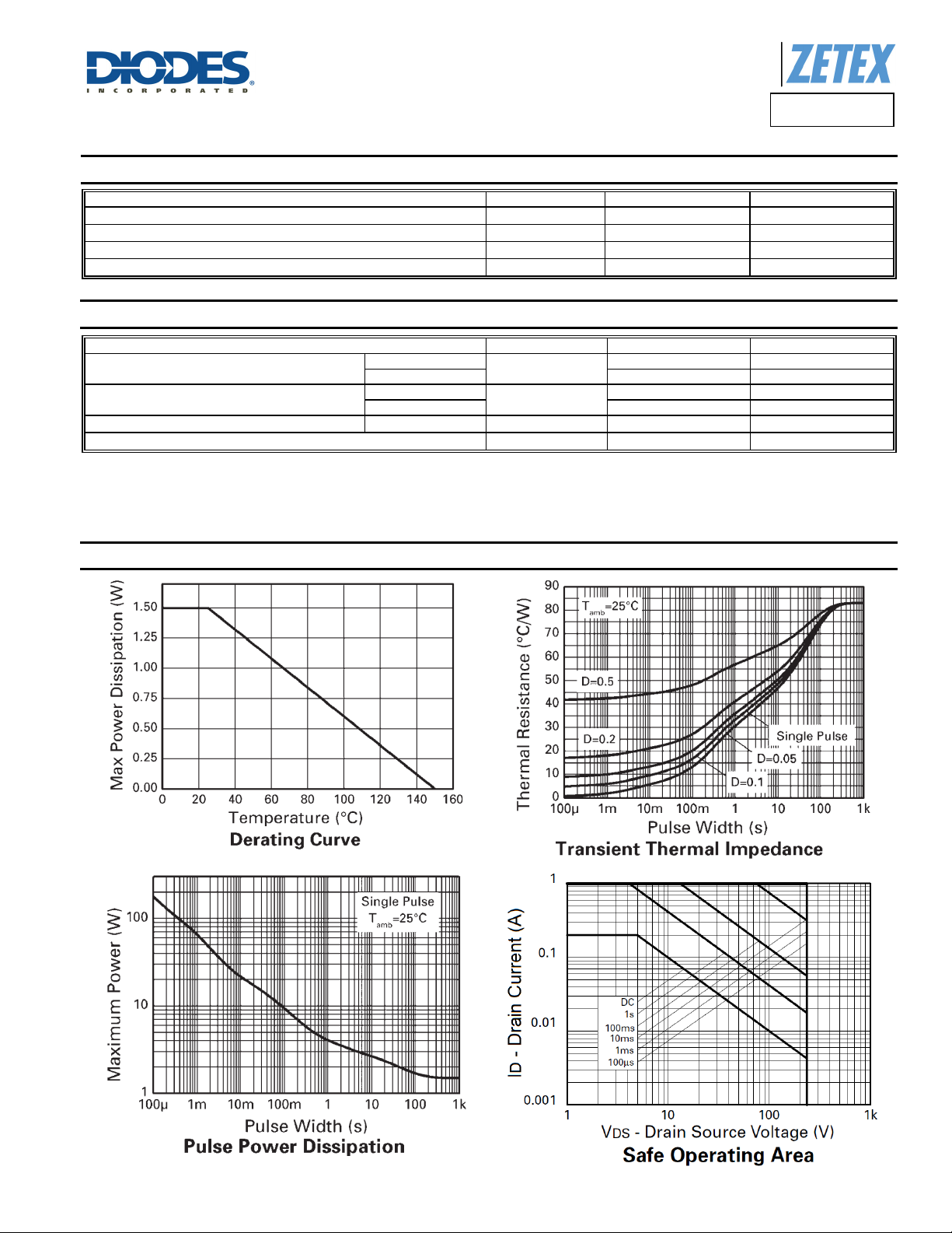
Thermal Characteristics
ZVP4424Z
Document Number DS33410 Rev. 2 - 2
2 of 6
www.diodes.com
December 2012
© Diodes Incorporated
 Loading...