

Page 1
Features
Epitaxial Construction
·
Guard Ring Die Construction for Transient Protection
·
Low Power Loss, High Efficiency
·
High Surge Capability
·
High Current Capability and Low Forward Voltage Drop
·
Surge Overload Rating to 150A Peak
·
For Use in Low Voltage, High Frequency Inverters, Free
·
Wheeling, and Polarity Protection Applications
Lead Free Finish, RoHS Compliant (Note 4)
·
Mechanical Data
Case: DO-201AD
·
Case Material: Molded Plastic. UL Flammability
·
Classification Rating 94V-0
Moisture Sensitivity: Level 1 per J-STD-020C
·
Terminals: Finish ¾ Bright Tin. Plated Leads Solderable
·
per MIL-STD-202, Method 208
Polarity: Cathode Band
·
Mounting Position: Any
·
Ordering Information: See Last Page
·
Marking: Type Number
·
·
Weight: 1.1 grams (approximate)
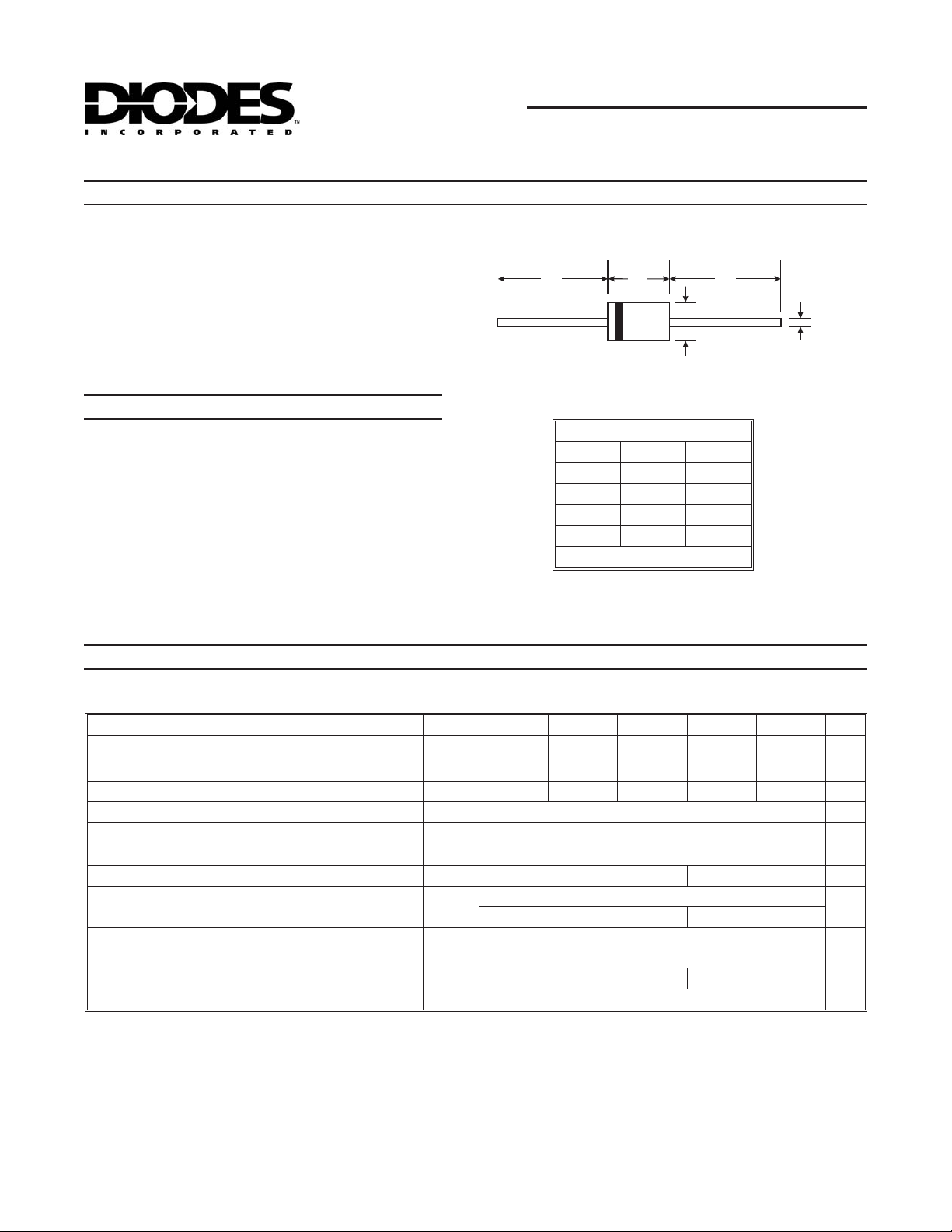
SB520 - SB560
5.0A SCHOTTKY BARRIER RECTIFIER
A
Dim Min Max
A
B
C
D
B
DO-201AD
25.40 ¾
7.20 9.50
1.20 1.30
4.80 5.30
All Dimensions in mm
A
C
D
Maximum Ratings and Electrical Characteristics
Single phase, half wave, 60Hz, resistive or inductive load.
For capacitive load, derate current by 20%.
Characteristic Symbol SB520 SB530 SB540 SB550 SB560 Unit
Peak Repetitive Reverse Voltage
Working Peak Reverse Voltage
DC Blocking Voltage
RMS Reverse Voltage
Average Rectified Output Current (See Figure 1) (Note 1)
Non-Repetitive Peak Forward Surge Current 8.3ms
single half sine-wave superimposed on rated load
(JEDEC Method)
Forward Voltage (Note 2) @ IF= 5.0A
Peak Reverse Current @ TA= 25°C
at Rated DC Blocking Voltage (Note 2) @ T
Typical Thermal Resistance Junction to Ambient (Note 1)
Operating Temperature Range
Storage Temperature Range
Notes: 1. Measured at ambient temperature at a distance of 9.5mm from case.
2. Short duration test pulse used to minimize self-heating effect.
3. Thermal resistance junction to lead vertical P.C.B. mounted, 0.375" (9.5mm) lead length.
4. RoHS revision 13.2.2003. Glass and High Temperature Solder Exemptions Applied, see
= 100°C
A
(Note 3)
V
V
V
R(RMS)
I
V
I
R
R
T
RRM
RWM
V
R
I
O
FSM
FM
RM
qJA
qJL
T
STG
j
@ TA= 25°C unless otherwise specified
20 30 40 50 60 V
14 21 28 35 42 V
5.0 A
150 A
0.55 0.67 V
0.5
50 25
25
8
-65 to +125 -65 to +150
-65 to +150
EU Directive Annex Notes 5 and 7.
mA
°C/W
°C
DS23024 Rev. 8 - 2 1 of 3 SB520 - SB560
www.diodes.com
ã Diodes Incorporated
Page 2
O
O
O
O
O
O
g
5
O
Resistive or
Inductive Load
100
4
10
I AVERAGE FORWARD CURRENT (A)
RWARD CURRENT (A)
US F
F(AV),
3
2
Resistive or Inductive Load
1
0.375” (9.5mm) lead length
0
02550
T , LEAD TEMPERATURE ( C)
L
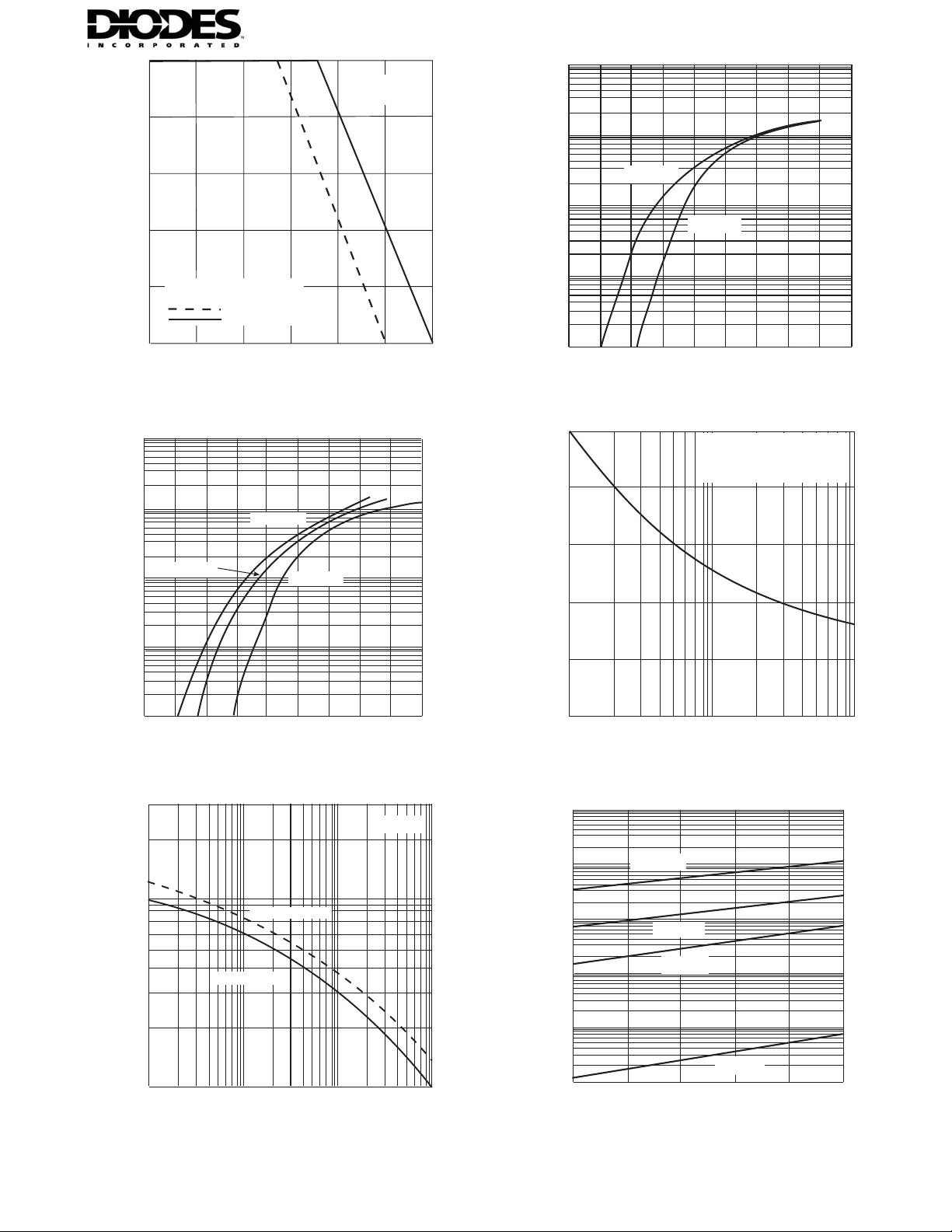
. 1 Forward Current DeratingCurve
Fi
100
10
T = 100°C
1.0
0.1
j
SB520 - SB540
SB550 & SB560
T = 125°C
j
75
100 125 150
T=25°C
j
T=100Cj°
RWARD CURRENT (A)
1.0
US F
T=25Cj°
0.1
F
I , INSTANTANE
0.01
0
°
0.2 0.4
V , INSTANTANEOUS FORWARD VOLTAGE (V)
F
0.6
0.8
Fig. 2 Typical Forward Characteristics, SB520 - SB540
150
8.3ms Single Half-Sine-Wave
(JEDEC Method)
T=T
j j(max)
120
90
60
RWARD SURGE CURRENT (A)
30
F
I , INSTANTANE
0.01
00.20.4
V , INSTANTANEOUS F0RWARD VOLTAGE (V)
F
0.6 0.8
Fig. 3 Typical Forward Characteristics, SB550 & SB560
3000
T=25Cj°
FSM
I , PEAK F
0
1 10 100
NUMBER OF CYCLES AT 60Hz
Fig. 4 Max Non-Repetitive Peak Fwd Surge Current
100
T = 125°C
10
j
1000
SB520 - SB540
TAL CAPACITANCE (pF)
T
C,T
100
0.1
SB550 - SB560
1.0 10
V , REVERSE VOLTAGE (V)
R
100
Fig. 5 Typical Total Capacitance
US REVERSE CURRENT (mA)
1.0
0.1
T = 100°C
j
T=75°C
j
0.01
T=25°C
0.001
R
I , INSTANTANE
0
V INSTANTANEOUS, REVERSE VOLTAGE (V)
R
8
16 24
,
j
32
Fig. 6 Typical Reverse Characteristics, SB520 - SB540
40
DS23024 Rev. 8 - 2 2 of 3 SB520 - SB560
www.diodes.com
Page 3

10,000
1000
100
10
1.0
T = 125°C
j
T = 100°C
j
T = 75°C
j
T = 25°C
j
0.1
0
V , INSTANTANEOUS REVERSE VOLTAGE (V)
R
10
20
30 40
Fig. 7 Typical Reverse Characteristics, SB550 & SB560
Ordering Information
(Note 5)
Device
SB520-A
SB520-B
SB520-T
SB530-A
SB530-B
SB530-T
SB540-A
SB540-B
SB540-T
SB550-A
SB550-B
SB550-T
SB560-A
SB560-B
SB560-T
50
60
Packaging Shipping
DO-201AD 1K/Ammo
DO-201AD 500/Bulk
DO-201AD 1.2K/Tape & Reel, 13-inch
DO-201AD 1K/Ammo
DO-201AD 500/Bulk
DO-201AD 1.2K/Tape & Reel, 13-inch
DO-201AD 1K/Ammo
DO-201AD 500/Bulk
DO-201AD 1.2K/Tape & Reel, 13-inch
DO-201AD 1K/Ammo
DO-201AD 500/Bulk
DO-201AD 1.2K/Tape & Reel, 13-inch
DO-201AD 1K/Ammo
DO-201AD 500/Bulk
DO-201AD 1.2K/Tape & Reel, 13-inch
Notes: 5. For packaging details, visit our website at http://www.diodes.com/datasheets/ap02008.pdf
IMPORTANT NOTICE
Diodes Incorporatedand its subsidiaries reserve the right to make modifications, enhancements, improvements, corrections or other changes without further
notice to any product herein. Diodes Incorporated does not assume any liability arising out of the application or use of any product described herein; neither
does it convey any license under its patent rights, nor the rights of others. The user of products in such applications shall assume all risks of such use and will
agree to hold Diodes Incorporated and allthe companies whose products are represented onour website, harmlessagainst all damages.
LIFE SUPPORT
Diodes Incorporated products are not authorized for use as criticalcomponents in lifesupport devices or systems without the expressedwritten approval ofthe
President of Diodes Incorporated.
DS23024 Rev. 8 - 2 3 of 3 SB520 - SB560
www.diodes.com
 Loading...