

Page 1
Features
NOT RECOMMENDED FOR NEW DESIGN
Diffused Junction
·
Fast Switching for High Efficiency
·
High Current Capability and Low Forward Voltage Drop
·
Surge Overload Rating to 50A Peak
·
Low Reverse Leakage Current
·
Lead Free Finish, RoHS Compliant (Note 4)
·
Mechanical Data
Case: DO-41, DO-15
·
Case Material: Molded Plastic. UL Flammability
·
Classification Rating 94V-0
Moisture Sensitivity: Level 1 per J-STD-020C
·
Terminals: Finish - Bright Tin. Plated Leads Solderable per
·
MIL-STD-202, Method 208
Polarity: Cathode Band
·
Ordering Information: See Last Page
·
Marking: Type Number
·
DO-41 Weight: 0.3 grams (approximate)
·
DO-15 Weight: 0.4 grams (approximate)
·
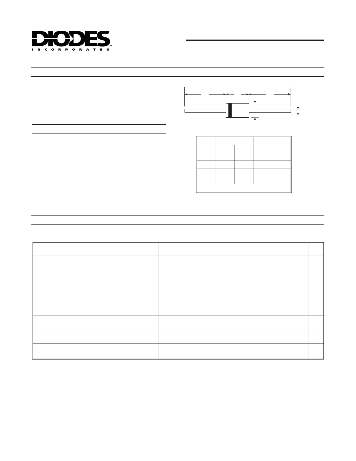
PR1501/S - PR1505/S
1.5A FAST RECOVERY RECTIFIER
A
Dim
A
B
C
D
“S” Suffix Designates DO-41 Package
No Suffix Designates DO-15 Package
B
DO-41 Plastic DO-15
Min Max Min Max
25.40 ¾ 25.40 ¾
4.06 5.21 5.50 7.62
0.71 0.864 0.686 0.889
2.00 2.72 2.60 3.60
All Dimensions in mm
A
C
D
Maximum Ratings and Electrical Characteristics
Single phase, half wave, 60Hz, resistive or inductive load.
For capacitive load, derate current by 20%.
Characteristic Symbol
Peak Repetitive Reverse Voltage
Working Peak Reverse Voltage
DC Blocking Voltage
RMS Reverse Voltage
Average Rectified Output Current
(Note 1) @ T
Non-Repetitive Peak Forward Surge Current
8.3ms Single half sine-wave Superimposed on Rated Load
(JEDEC Method)
Forward Voltage @ IF= 1.5A
Peak Reverse Current @ TA= 25°C
at Rated DC Blocking Voltage @ T
Reverse Recovery Time (Note 3)
Typical Junction Capacitance (Note 2)
Typical Thermal Resistance Junction to Ambient
Operating and Storage Temperature Range
Notes: 1. Valid provided that leads are maintained at ambient temperature at a distance of 9.5mm from the case.
2. Measured at 1.0MHz and applied reverse voltage of 4.0V DC.
3. Measured with I
4. RoHS revision 13.2.2003. Glass and High Temperature Solder Exemptions Applied, see
= 0.5A, IR= 1.0A, Irr= 0.25A. See figure 5.
F
= 50°C
A
= 100°C
A
V
V
V
R(RMS)
I
V
I
R
T
j,TSTG
RRM
RWM
V
R
I
O
FSM
FM
RM
t
rr
C
qJA
j
@ TA= 25°C unless otherwise specified
PR
1501/SPR1502/SPR1503/SPR1504/SPR1505/S
50 100 200 400 600 V
35 70 140 280 420 V
150 250 ns
20 10 pF
-65 to +150 °C
EU Directive Annex Notes 5 and 7.
Unit
1.5 A
50 A
1.2 V
5.0
100
35 K/W
mA
DS26011 Rev. 4 - 2 1 of 3 PR1501/S - PR1505/S
www.diodes.com
ã Diodes Incorporated
Page 2
1
(AV)
g
10
g
60
g
100
g
NOT RECOMMENDED FOR NEW DESIGN
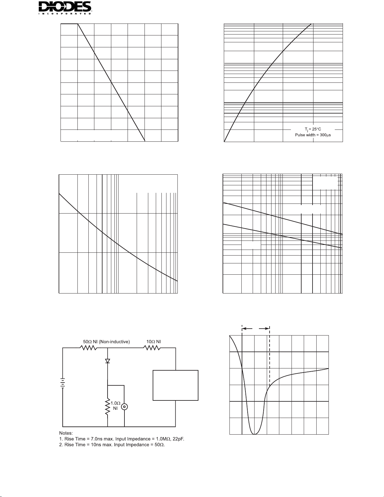
I , AVERAGE FWD RECTIFIED CURRENT (A)
.5
1.2
0.9
0.6
0.3
Single phase half-wave
60 Hz resistive or inductive load
0
25 50
T , AMBIENT TEMPERATURE ( C)
75
100 125 150 175 200
A
Fi
. 1 Forward DeratingCurve
1.0
0.1
F
I , INSTANTANEOUS FWD CURRENT (A)
0.01
0.6 0.8 1.0 1.2 1.4
°
V , INSTANTANEOUS FORWARD VOLTAGE (V)
F
Fi
.2 Typical Forward Characteristics
Pulse Width 8.3ms
Single Half-Sine-Wave
(JEDEC Method)
40
20
FSM
I , PEAK FORWARD SURGE CURRENT (A)
0
1 10 100
NUMBER OF CYCLES AT 60Hz
Fi
. 3 Peak Forward Surge Current
Device
Under
(+)
50V DC
Approx
(-)
Te st
(-)
Pulse
Generator
(Note 2)
PR1501 - PR1504
10
j
C , CAPACITANCE (pF)
PR1505
1
1 10 100
V , REVERSE VOLTAGE (V)
R
Fi
.4 Typical Junction Capacitance
t
rr
+0.5A
0A
-0.25A
T=25C
°
A
f = 1.0MHz
Oscilloscope
(Note 1)
Fig. 5 Reverse RecoveryTime Characteristic and Test Circuit
DS26011 Rev. 4 - 2 2 of 3 PR1501/S - PR1505/S
(+)
-1.0A
Set time base for 50/100 ns/cm
www.diodes.com
Page 3

Ordering Information
NOT RECOMMENDED FOR NEW DESIGN
Device
PR1501S-A
PR1501S-B
PR1501S-T
PR1502S-A
PR1502S-B
PR1502S-T
PR1503S-A
PR1503S-B
PR1503S-T
PR1504S-A
PR1504S-B
PR1504S-T
PR1505S-A
PR1505S-B
PR1505S-T
PR1501-B
PR1501-T
PR1502-B
PR1502-T
PR1503-B
PR1503-T
PR1504-B
PR1504-T
PR1505-B
PR1505-T
(Note 5)
Packaging Shipping
DO-41 5K/Ammo Pack
DO-41 1K/Bulk
DO-41 5K/Tape & Reel, 13-inch
DO-41 5K/Ammo Pack
DO-41 1K/Bulk
DO-41 5K/Tape & Reel, 13-inch
DO-41 5K/Ammo Pack
DO-41 1K/Bulk
DO-41 5K/Tape & Reel, 13-inch
DO-41 5K/Ammo Pack
DO-41 1K/Bulk
DO-41 5K/Tape & Reel, 13-inch
DO-41 5K/Ammo Pack
DO-41 1K/Bulk
DO-41 5K/Tape & Reel, 13-inch
DO-15 1K/Bulk
DO-15 4K/Tape & Reel, 13-inch
DO-15 1K/Bulk
DO-15 4K/Tape & Reel, 13-inch
DO-15 1K/Bulk
DO-15 4K/Tape & Reel, 13-inch
DO-15 1K/Bulk
DO-15 4K/Tape & Reel, 13-inch
DO-15 1K/Bulk
DO-15 4K/Tape & Reel, 13-inch
Notes: 5. For packaging details, visit our website at http://www.diodes.com/datasheets/ap02008.pdf
IMPORTANT NOTICE
Diodes Incorporatedand its subsidiaries reserve the right to make modifications, enhancements, improvements, corrections or other changes without further
notice to any product herein. Diodes Incorporated does not assume any liability arising out of the application or use of any product described herein; neither
does it convey any license under its patent rights, nor the rights of others. The user of products in such applications shall assume all risks of such use and will
agree to hold Diodes Incorporated and allthe companies whoseproducts are represented onour website, harmlessagainst all damages.
LIFE SUPPORT
Diodes Incorporated productsare not authorized for use as criticalcomponents in lifesupport devices orsystems without the expressed written approval of the
President of Diodes Incorporated.
DS26011 Rev. 4 - 2 3 of 3 PR1501/S - PR1505/S
www.diodes.com
 Loading...