

Page 1
Data Sheet
Enhanced Multi-touch Capacitive Touch Screen Controller CS5519
General Description
The CS5519 is a low-cost high-resolution single chip
solution for APA capacitive touch screen. It is an
8-bit single cycle 8051 microcontroller with I
Interface. The chip includes 8-bit successive
approximation analog-to-digital converters with an
2
I
C interface and multiplexer-switcher circuits for
flexible measurement of analog signal from APA
panel. An accurate switched-capacitor integrator is
built-in and it can auto calibrate the pixel parameters
for a wide range of capacitance on the touch screen
(0.1pF to 4pF). On-chip capacitor can replace
external component. This touch screen controller
(TSC) with CMOS integration circuit provides an
ideal choice for APA touch panel. The CS5519 is
specified over the temperature range of -40°C to
95°C.
The CS5519 is available in QFN-7×7-56 and
QFN-8×8-68 packages.
2
Features
•
Mutual Capacitive Touch Sensing
• Dual Power Supply: 2.8V to 3.6V Operation
Voltage; 1.6V to 2.0V Operation Voltage
•
Up to 38/30 Drive Lines and 22/17 Sense Lines
• Dedicated Internal Two-wire Serial Control Bus
2
C and UART between CS5519 and Host
I
•
Single-end Integrator with Programmable Gain
Control and Offset Control
• Multiplexed Analog Digitization with Two 8-bit
Resolution Odd/Even Scan SAR ADCs and Its
Dedicated 2X to 8X Accumulator XSRAM
Buffers
QFN-7×7-56
Figure 1. Package Types of CS5519
Features (Continued)
• Single Cycle 8051 CPU Core, Maximum Opera-
ting Clock up to 24MHz from IOSC (Zero Wait
C
State); 48MHz from IOSC(With Wait State)
4MHz to 48MHz Internal Oscillator (IOSC)
64K-byte Flash ROM
256-byte Internal SRAM and 12032-byte
XSRAM
Extra XSRAMs for AFE:
896×12-bit×2 XSRAM for 8-bit SAR ADC
896×8-bit XSRAM for 8-bit Parasitical
Capacitor Compensator
Two 16-bit Timers T0/T1 and One 16-bit ECT
Timer T2
2
One I
C Slave Controller and One I2C Master
Controller Shared with the Same Port
With Asynchronous I
Detection Logic Design
4 General Purpose GPIO Pins
One External Interrupt Pin
One UART Data Transfer Output Pin
• ISP/IAP via I²C Port
• Operation Temperature Range: -40°C to 95°C
• Package Types: QFN-7×7-56 and QFN-8×8-68
• RoHS Compliance
•
Operating Mode:
Mode Description
Power-down No scan with power-down mode
Standard Higher scan rate when fingers are
on panel, IOSC can up to 4MHz
to 48MHz
2
C Slave Address
Applications
• Mobile Phones
• Personal Digital Assistants
• Smart Hand-held or Gaming Devices
QFN-8×8-68
Apr. 2013 Rev. 1. 0 BCD Semiconductor Manufacturing Limited
1
Page 2
Data Sheet
Enhanced Multi-touch Capacitive Touch Screen Controller CS5519
Pin Configuration
FN Package
(QFN-7×7-56)
Pin 1 Mark
56
1
2
3
4
5
6
7
8
9
10
11
12
13
14
15
16
17 18 19 20 21 22 23 24 25 26 27 28
EP
43444546474849505152535455
42
41
40
39
38
37
36
35
34
33
32
31
30
29
Figure 2. Pin Configuration of CS5519 (56-pin) (Top View)
Apr. 2013 Rev. 1. 0 BCD Semiconductor Manufacturing Limited
2
Page 3
Data Sheet
Enhanced Multi-touch Capacitive Touch Screen Controller CS5519
Pin Configuration (Continued)
FN Package
(QFN-8×8-68)
Pin 1 Mark
S8
P1.7/
TXD1
/PINT0.1/EXTCLKIN
TESTEN
P1.2/SDA
P1.3/SCL
RSTN
D38
D37
D36
D35
D34
D33
D32
D31
D30
D29
D28
D27
/T0
S22
68
1
2
3
4
5
6
7
8
9
10
11
12
13
14
15
16
17
18
S19
S20
S21
67
66
65
202122232425262728293031323334
19
S16
S14
S15
S17
S18
63626160595857
64
EP
S13
S11
S10
S12
5655545352
69 VSS
S9
S7
S6
51
S5
50
S4
49
S3
48
S2
47
S1
46
VDD33
45
VDD18
44
P3.6/RXD1(GPIO18)
43
D1
42
D2
41
D3
40
D4
39
D5
38
D6
37
D7
36
D8
35
D9
D24
D22
D26
D25
D23
D21
D20
D19
D18
D17
D16
D15
D14
D13
D12
D11
D10
Figure 3. Pin Configuration of CS5519 (68-pin) (Top View)
Apr. 2013 Rev. 1. 0 BCD Semiconductor Manufacturing Limited
3
Page 4
Data Sheet
Enhanced Multi-touch Capacitive Touch Screen Controller CS5519
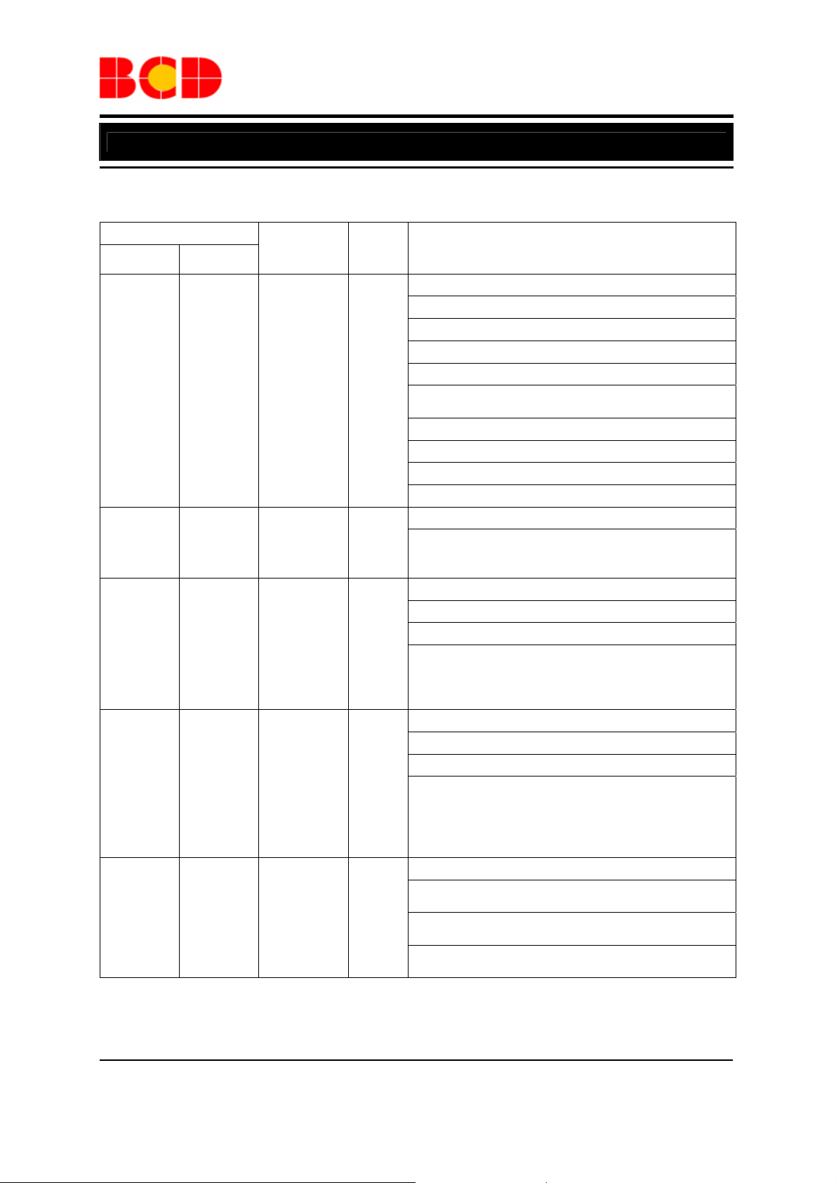
Pin Description
Pin Number
QFN-7×7
-56
1 1
2 2 TESTEN I
3 3
4 4
5 5 RSTN I
QFN-8×8
-68
Pin Name
P1.7/
TXD1/
PINT0.1/
EXTCLKIN/
T0
P1.2/SDA
(open-
drain)
P1.3/SCL
(open-
drain)
Pin
Type
I/O
I/O
I/O
Pin Function
Port 1.7 GPIO
8051 P1.7 GPIO
TXD1
This pin also can be configured as TXD of UART 1
PINT0.1
This pin also can be configured as the expanded INT0
interrupt
External Clock Input
External clock input source.
T0 Timer 0 Input
This pin also can be configured as Timer 0 input
Test Mode Enable High Active
This pin has an internal weakly pull low resistor
connected. If it is connected high , the chip enters into
Test Mode condition
Port 1.2 GPIO
8051 P1.2 GPIO
SDA
This pin also can be configured as the SDA signal of
the I2C master or I2C slave controller. In this operation
mode, this pin should also be configured as
bi-directional I/O with open-drain output
Port 1.3 GPIO
8051 P1.3 GPIO
SCL
This pin also can be configured as the SCL signal of
2
the I
C master or I2C slave controller. In I2C master
mode, this pin should be configured as open-drain
output. In I
input only
Reset Low Active
Typically connect a resistor to VDD18 and a capacitor
to VSS
Low asserted and threshold at 0.5×V
low, the chip enters into reset condition
This pin should not be connected to any level above
V
DD18
2
C slave, this pin should be configured as
DD18
. When forced
Apr. 2013 Rev. 1. 0 BCD Semiconductor Manufacturing Limited
4
Page 5
Data Sheet
Enhanced Multi-touch Capacitive Touch Screen Controller CS5519
Pin Description (Continued)
Pin Number
QFN-7×7
-56
- 6 to 13
6 to 35 14 to 43
36 44
37 69 VSS Power
38 45 VDD18 Power
39 46 VDD33 Power
40 to 56 47 to 63
- 64 to 68
QFN-8×8
-68
Pin
Name
D38 to
D31
D30 to
D1
P3.6/
RXD1
(open-
drain)
S1 to
S17
S18 to
S22
Pin
Type
O, A
O, A
I/O
I, A
I, A
Pin Function
D38, D37, D36, D35, D34, D33, D3 2, D31
Driving line 38 to line 31
D30, D29, D28, D27, D26, D25, D24, D23, D22, D21,
D20, D19, D18, D17, D16, D15, D14, D13, D12, D11,
D10, D9, D8, D7, D6, D5, D4, D3, D2, D1
Driving line 30 to line 1
Port 3.6 GPIO
8051 P3.6 GPIO
This pin should be configured as open-drain output and
the input range can be 1.8V to 3.3V
RXD1
This pin also can be configured as RXD of UART 1
Ground Voltage. 0V
Internal Regulator Output. 1. 6V to 2.0V
Typical decoupling capacitors of 0.1F and 10F should
be connected between VDD18 and VSS
Supply Voltage. 2.8V to 3.6V
A good decoupling capacitor between VDD33 and VSS is
critical for good performance
S1, S2, S3, S4, S5, S6, S7, S8, S9, S10, S11, S12, S13,
S14, S15, S16, S17
Sensing line 1to line 17
S18, S19, S20, S21, S22
Sensing line 18 to line 22
Apr. 2013 Rev. 1. 0 BCD Semiconductor Manufacturing Limited
5
Page 6
Data Sheet
Enhanced Multi-touch Capacitive Touch Screen Controller CS5519
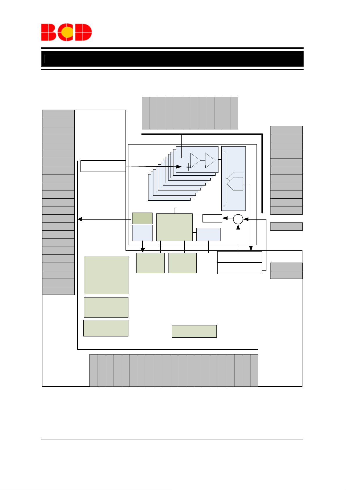
Functional Block Diagram
VSS
P1.7
TESTEN
SDA
SCL
RSTN
D38
D37
D36
D35
D34
D33
D32
D31
D30
D29
D28
D27
D26
D25
D24
D23
D22
896ٛ8-bit SRAM
(CMOD_Buffer)
64K Flash
D[38:1]
MUX
POR18
POR33
LVD
S23
INT
S22
S21
S20
S19
Stage 4
Stage 5
Stage 6
Stage 7
Stage 8
Stage 9
/
Stage 23
Mode Control
Register Table
SFR
S18
Analog signals S[23:1]
DAI S/H
Stage 1
Stage 2
Stage 3
S17
Stage 0
S15
S16
FIFO
4~48M
OSC
CLK
12K SRAM
MCU
MDU
I2C M/S
D12
D13
D14
D15
D16
D17
D18
D19
D20
D21
D9
D11
D10
D8
D7
D6
Figure 4. Main AFE I/O Pin Assignment and Whole Chip’s Functional Block Diagram
Apr. 2013 Rev. 1. 0 BCD Semiconductor Manufacturing Limited
6
S12
S13
S14
SWITCH MATRIX
SAR
8-bit
SAR
ADC
8-bit
ADC
+
896ٛ12-bit SRAM
(SCAN_Buffer)
896ٛ12-bit SRAM
(Baseline)
D4
D3
D5
D2
S11
S10
S9
S8
S7
S6
S5
S4
S3
S2
S1
-
VDD33
VDD18
P3.6
D1
Page 7

Data Sheet
Enhanced Multi-touch Capacitive Touch Screen Controller CS5519
Ordering Information
CS5519 -
Circuit Type
CJ: 56-pin
Package
QFN-7x7-56
QFN-8x8-68
BCD Semiconductor's Pb-free products, as designated with "G1" in the part number, are RoHS compliant and
green.
AJ: 68-pin
I1: -40 to 95°C
I2: -40 to 85°C
I3: -40 to 80°C
Temperature
Range
-40 to 95°C
-40 to 85°C
-40 to 80°C
-40 to 95°C
-40 to 85°C
-40 to 80°C
Part Number Marking ID Packing Type
CS5519CJI1FN-G1 CS5519CJ-I1 Tray
CS5519CJI1FNTR-G1 CS5519CJ-I1 Tape & Reel
CS5519CJI2FN-G1 CS5519CJ-I2 Tray
CS5519CJI2FNTR-G1 CS5519CJ-I2 Tape & Reel
CS5519CJI3FN-G1 CS5519CJ-I3 Tray
CS5519CJI3FNTR-G1 CS5519CJ-I3 Tape & Reel
CS5519AJI1FN-G1 CS5519AJ-I1 Tray
CS5519AJI1FNTR-G1 CS5519AJ-I1 Tape & Reel
CS5519AJI2FN-G1 CS5519AJ-I2 Tray
CS5519AJI2FNTR-G1 CS5519AJ-I2 Tape & Reel
CS5519AJI3FN-G1 CS5519AJ-I3 Tray
CS5519AJI3FNTR-G1 CS5519AJ-I3 Tape & Reel
G1: Green
Blank: Tray
TR: Tape & Reel
Package
FN: QFN-7x7-56
/QFN-8x8-68
Apr. 2013 Rev. 1. 0 BCD Semiconductor Manufacturing Limited
7
Page 8

Data Sheet
Enhanced Multi-touch Capacitive Touch Screen Controller CS5519
CS5519 Support 7” to 13” Touch Panel, Listed Below:
PN TX/ RX Multi - Touch Package Panel size
CS5519
30/17 10 point 100HZ QFN-7x7-56 7” to 10”
38/22 10 point 100HZ QFN-8x8-68 8” to 13”
Absolute Maximum Ratings (Note 1)
Parameter Symbol Value Unit
Supply Voltage 1 VDD 2.8 to 3.6 V
Supply Voltage 2 V
Analog Input Voltage (Other pins) V
Logic Input Voltage V
Power Dissipation PD 250 mW
Maximum Junction Temperature TJ 100 °C
Operating T em perature TOP -40 to 95 °C
Storage Temperature T
1.6 to 2.0 V
DD18
-0.3 to VDD+0.3 V
DDA
-0.3 to VDD+0.3 V
DDD
-65 to 150 °C
STG
Note 1: Stresses greater than those listed under “Absolute Maximum Ratings” may cause permanent damage to
the device. These are stress ratings only, and functional operation of the device at these or any other conditions
beyond those indicated under “Recommended Operating Conditions” is not implied. Exposure to “Absolute
Maximum Ratings” for extended periods may affect device reliability.
Apr. 2013 Rev. 1. 0 BCD Semiconductor Manufacturing Limited
8
Page 9

Data Sheet
Enhanced Multi-touch Capacitive Touch Screen Controller CS5519
Electrical Characteristics
DA/AC Characteristics for AFE
TA=–40°C to 95°C, VDD=3.3V, I2C bus frequency=400kHz, unless otherwise noted.
Parameter Symbol Test Condition Min Typ Max Unit
ADC DC Accuracy
Resolution 8 Bits
No Missing Codes
Integral Linearity Error INL
Differential Linearity Error
Offset Error
DNL External V
Gain Error
Analog Input
Full-scale Input Span
Absolute Input Range
ADC Sampling Dynamics
Throughput Rate 500 ksps
Reference Input
Input Voltage Range 1.8 VDD V
Switched-capacitor Integrator
Output Voltage Range 0.3 VDD-0.3 V
Integrator Capacitor C
INT
Digital Input/Output
Logic Family CMOS
Input High Voltage VIH 0.7×VDD V
Input Low Voltage VIL -0.3 0.3×VDD V
Output High Voltage VOH 0.8×VDD V
Output Low Voltage VOL 0.4 V
Input High Voltage for
P3.6 (GPIO18)
Input Low Voltage for P3.6
(GPIO18)
Output High Voltage for
P3.6 (GPIO18)
Output Low Voltage for
P3.6 (GPIO18)
V
V
V
V
IH18
IL18
OH18
OL18
Power Supply
Supply Voltage VDD Operating voltage 2.8 3.6 V
Quiescent Current
Temperature Range
Specified Performance -40 95 °C
Standard/Fast
Standard/Fast
REF
6 8 Bits
±2 LSB
0
-0.2
±1
V
±2
±1
VDD
+0.2
DD
LSB
LSB
LSB
V
V
12 pF
+0.3 V
DD
0.7×V
DD18
-0.3 0.3×V
0.8×V
DD18
0.2×V
Standard mode:
IOSC=4MHz to
48MHz
Power-down mode
V
+0.3 V
DD18
V
DD18
V
V
DD18
TBD
10
mA
A
Apr. 2013 Rev. 1. 0 BCD Semiconductor Manufacturing Limited
9
Page 10

Data Sheet
Enhanced Multi-touch Capacitive Touch Screen Controller CS5519
Electrical Characteristics (Continued)
DA/AC Characteristics for AFE
TA=–40°C to 95°C, VDD=3.3V, I2C bus frequency=400kHz, unless otherwise noted.
Parameter Symbol Test Condition Min Typ Max Unit
3.3V-to-1.8V LDO
Internal 1.8V Regulator
Output
Output Voltage Trimming
Level
Internal OSC
Frequency 4 48 MHz
Operating Current
Frequency Trimming
Level
V
,
DD18
15mA
1.6 1.8 2.0 V
-2/4/6 0 2/4/6 %
Operating
frequency=12MHz
-10/20/30 0 10/20/30 %
50
A
Apr. 2013 Rev. 1. 0 BCD Semiconductor Manufacturing Limited
10
Page 11

Data Sheet
Enhanced Multi-touch Capacitive Touch Screen Controller CS5519
Electrical Characteristics (Continued)
DA/AC Characteristics for 8051 CPU Core, Digital GPIO pins, Digital Peripherals, and
IOSC
T
=–40°C to 95°C, VDD=2.8V to 3.6V, unless otherwise noted.
A
Parameter Symbol Min Typ Max Unit Note
Power Supply Current
Normal Mode Supply Current
Using IOSC up to 48MHz
Normal Mode Supply Current
Using IOSC=4MHz
PMM Mode Supply Current Using
IOSC up to 48MHz
PMM Mode Supply Current Using
IOSC=4MHz
Idle Mode Supply Current Using
IOSC up to 48MHz
Stop Mode Supply Current Using
IOSC Keeps Low
I
, normal IOSC1 25 mA 2
DD
I
, normal IOSC2 2.9 mA 2
DD
I
, PMM IOSC1 6 mA 2
DD
, PMM IOSC2 1.5 mA 2
I
DD
I
, idle IOSC1 3 mA 2
DD
I
, stop 3
DD
A
2
Digital GPIO Characteristics
Input High Voltage VIH 2 3.6 V 3
Input Low Voltage VIL -0.3 0.8 V 3
Output High Voltage VOH 2.4 V 3
Output Low Voltage VOL 0.4 V 3
I
(2mA) 3.0 7.87 12.9 mA
High Level Output Current
@V
(min)
OH
Low Level Output Current
@V
(max)
OL
Input Pull Up Resistance RPU 34 74
Input Pull Down Resistance RPD 29 86
OH
IOH(4mA) 7.7 15.6 25.8 mA
I
(2mA) 3.4 5.4 7.4 mA
OL
IOL(4mA) 6.7 10.7 14.7 mA
k
k
3
3
Input Low to High Level, RSTN VIH, RSTN 0.85 0.93 V 4
Input High to Low Level, RSTN VIL, RSTN 0.63 0.71 V 4
Output Rise Time t
Output Fall Time t
5 ns 7
RISE
5 ns 7
FALL
Internal 3.3V-to-1.8V LDO from AFE
Internal 1.8V Regulato r Output V
Power On/Off Reset Level V
, 15mA 1.6 1.8 2.0 V 5
DD18
, Reset 80 85 90 % 6
DD18
Note 2: Does not include load current and tested under NOP loop and all peripheral disabled.
Note 3: For Digital I/O only.
Note 4: For RSTN pin only.
Note 5: Supply to internal digital and analog circuit only.
Note 6: This is measured as the percentage of steady state value of V
DD18
.
Note 7: This is measured with 20pF load and 20% to 80% output level.
Apr. 2013 Rev. 1. 0 BCD Semiconductor Manufacturing Limited
11
Page 12

Data Sheet
Enhanced Multi-touch Capacitive Touch Screen Controller CS5519
Typical Application
CS5519
Figure 5. Typical Application Schematic of CS5519 (For QFN-7×7-56 Package)
CS5519
Figure 6. Typical Application Schematic of CS5519 (For QFN-8×8-68 Package)
Apr. 2013 Rev. 1. 0 BCD Semiconductor Manufacturing Limited
12
Page 13

Data Sheet
Enhanced Multi-touch Capacitive Touch Screen Controller CS5519
Mechanical Dimensions
QFN-7×7-56 Unit: mm(inch)
Apr. 2013 Rev. 1. 0 BCD Semiconductor Manufacturing Limited
13
Page 14

Data Sheet
Enhanced Multi-touch Capacitive Touch Screen Controller CS5519
Mechanical Dimensions (Continued)
QFN-8×8-68 Unit: mm(inch)
7.900(0.311)
8.100(0.319)
0.700(0.028)
0.800(0.031)
7.900(0.311)
8.100(0.319)
Pin 1 Mark
0.000(0.000)
0.050(0.002)
0.203(0.008)
REF
0.300(0.012)
0.500(0.020)
E
N35
0.400(0.016)
68
67
66465
N52
BSC
1
2
3
D
0.150(0.006)
0.250(0.010)
DETAIL A
68
67
66465
Pin 1 Options
PIN
#1 IDENTIFICATION
See DETAIL A
N68
N1
N18
68
67
66465
1
2
3
1
2
3
4.500
5.600
D
0.169 0.177
0.213 0.220
4.300
.
5.400
.
Symbol
min(mm) max(mm) max(mm)min(mm)min(inch) min(inch)max(inch) max(inch)
Option1
Option2
4.300
5.400
Option3 6.100 6.300 0.240 0.248 6.3006.100 0.240 0.248
4.500
5.600
E
0.169
0.213
0.177
0.220
Apr. 2013 Rev. 1. 0 BCD Semiconductor Manufacturing Limited
14
Page 15

Data Sheet
Enhanced Multi-touch Capacitive Touch Screen Controller CS5519
Mounting Pad Layout
QFN-7×7-56
X
Y
Y2
E
Y3
X1
E
X2
X3
Y1
Dimensions
Value 7.400/0.291 5.400/0.213 0.250/0.010 0.700/0.028 0.400/0.016
X=Y
(mm)/(inch)
X1=Y1
(mm)/(inch)
X2=Y2
(mm)/(inch)
X3=Y3
(mm)/(inch) E (mm)/(inch)
Apr. 2013 Rev. 1. 0 BCD Semiconductor Manufacturing Limited
15
Page 16

Data Sheet
Enhanced Multi-touch Capacitive Touch Screen Controller CS5519
Mounting Pad Layout (Continued)
QFN-8×8-68
Dimensions
Option1 8.400/0.331 4.700/0.185 0.250/0.010 0.400/0.016 0.700/0.028
Option2 8.400/0.331 5.800/0.228 0.250/0.010 0.400/0.016 0.700/0.028
Option3 8.400/0.331 6.500/0.256 0.250/0.010 0.400/0.016 0.700/0.028
X=Y
(mm)/(inch)
X1=Y1
(mm)/(inch)
X2=Y2
(mm)/(inch) E (mm)/(inch)
X3=Y3
(mm)/(inch)
Apr. 2013 Rev. 1. 0 BCD Semiconductor Manufacturing Limited
16
Page 17

BCD Semiconductor Manufacturing Limited
IMPORTANT NOTICE
http://www.bcdsemi.com
BCD Semiconductor Manufacturing Limited reserves the right to make changes without further notice to any products or specifications herein. BCD Semiconductor Manufacturing Limited does not assume any responsibility for use of any its products for any
IMPORTANT NOTICE
IMPORTANT NOTICE
particular purpose, nor does BCD Semiconductor Manufacturing Limited assume any liability arising out of the application or use
of any its products or circuits. BCD Semiconductor Manufacturing Limited does not convey any license under its patent rights or
BCD Semiconductor Manufacturing Limited reserves the right to make changes without further notice to any products or specifi-
BCD Semiconductor Manufacturing Limited reserves the right to make changes without further notice to any products or specifi-
other rights nor the rights of others.
cations herein. BCD Semiconductor Manufacturing Limited does not assume any responsibility for use of any its products for any
cations herein. BCD Semiconductor Manufacturing Limited does not assume any responsibility for use of any its products for any
particular purpose, nor does BCD Semiconductor Manufacturing Limited assume any liability arising out of the application or use
particular purpose, nor does BCD Semiconductor Manufacturing Limited assume any liability arising out of the application or use
MAIN SITE
of any its products or circuits. BCD Semiconductor Manufacturing Limited does not convey any license under its patent rights or
of any its products or circuits. BCD Semiconductor Manufacturing Limited does not convey any license under its patent rights or
- Headquarters
BCD (Shanghai) Micro-electronics Limited
other rights nor the rights of others.
other rights nor the rights of others.
No. 1600, Zi Xing Road, Shanghai ZiZhu Science-based Industrial Park, 200241, P. R.C.
Tel: +86-021-2416-2266, Fax: +86-021-2416-2277
MAIN SITE
MAIN SITE
REGIONAL SALES OFFICE
- Headquarters
BCD Semiconductor Manufacturing Limited
BCD Semiconductor Manufactur ing Limited
Shenzhen Office
- Wafer Fab
No. 1600, Zi Xing Road, Shanghai ZiZhu Science-based Industrial Park, 200241, China
Shanghai SIM-BCD Semiconductor Manufacturing Co., Ltd., Shenzhen Office
Shanghai SIM-BCD Semiconductor Manufacturing Limited
Tel: +86-21-24162266, Fax: +86-21-24162277
Unit A Room 1203,Skyworth Bldg., Gaoxin Ave.1.S., Nanshan District
800, Yi Shan Road, Shanghai 200233, China
Shenzhen 518057, China
Tel: +86-21-6485 1491, Fax: +86-21-5450 0008
REGIONAL SALES OFFICE
Tel: +86-0755-8660-4900, Fax: +86-0755-8660-4958
Shenzhen Office
REGIONAL SALES OFFICE
Shanghai SIM-BCD Semiconductor Manufacturing Co., Ltd., Shenzhen Office
Taiwan Office (Hsinchu)
Shenzhen Office
Unit A Room 1203, Skyworth Bldg., Gaoxin Ave.1.S., Nanshan District, Shenzhen,
BCD Semiconductor (Taiwan) Company Limited
Shanghai SIM-BCD Semiconductor Manufacturing Co., Ltd. Shenzhen Office
China
8F, No.176, Sec. 2, Gong-Dao 5th Road, East District
Advanced Analog Circuits (Shanghai) Corporation Shenzhen Office
Tel: +86-755-8826 7951
HsinChu City 300, Taiwan, R.O.C
Room E, 5F, Noble Center, No.1006, 3rd Fuzhong Road, Futian District, Shenzhen 518026, China
Fax: +86-755-8826 7865
Tel: +886-3-5160181, Fax: +886-3-5160181
Tel: +86-755-8826 7951
Fax: +86-755-8826 7865
- Wafer Fab
Shanghai SIM-BCD Semiconductor Manufacturing Co., Ltd.
800 Yishan Road, Shanghai 200233, China
Tel: +021-6485-1491, Fax: +86-021-5450-0008
- Wafer Fab
BCD Semiconductor Manufacturing Limited
Shanghai SIM-BCD Semiconductor Manufacturing Co., Ltd.
Taiwan Office (Taipei)
- IC Design Group
800 Yi Shan Road, Shanghai 200233, China
BCD Semiconductor (Taiwan) Company Limited
Advanced Analog Circuits (Shanghai) Corporation
Tel: +86-21-6485 1491, Fax: +86-21-5450 0008
3F, No.17, Lane 171, Sec. 2, Jiu-Zong Rd., Nei-Hu Dist., Taipei(114), Taiwan, R.O.C
8F, Zone B, 900, Yi Shan Road, Shanghai 200233, China
Tel: +886-2-2656 2808
Tel: +86-21-6495 9539, Fax: +86-21-6485 9673
Fax: +886-2-2656-2806/26562950
Taiwan Office
BCD Semiconductor (Taiwan) Company Limited
USA Office
Taiwan Office
4F, 298-1, Rui Guang Road, Nei-Hu District, Taipei,
BCD Semiconductor Corp.
BCD Semiconductor (Taiwan) Company Limited
Tai wan
48460 Kato Road, Fremont, CA 94538, USA
4F, 298-1, Rui Guang Road, Nei-Hu District, Taipei,
Tel: +886-2-2656 2808
Tel: +1-510-668-1950
Taiwan
Fax: +886-2-2656 2806
Fax: +1-510-668-1990
Tel: +886-2-2656 2808
Fax: +886-2-2656 2806
USA Office
Korea Office
BCD Semiconductor Limited Korea office.
Room 101-1112, Digital-Empire II, 486 Sin-dong,
Yeongtong-Gu, Suwon-city, Gyeonggi-do, Korea
Tel: +82-31-695-8430
BCD Semiconductor Corp.
USA Office
30920 Huntwood Ave. Hayward,
BCD Semiconductor Corporation
CA 94544, USA
30920 Huntwood Ave. Hayward,
Tel : +1-510-324-2988
CA 94544, U.S.A
Fax: +1-510-324-2788
Tel : +1-510-324-2988
Fax: +1-510-324-2788
 Loading...