

Page 1
BSP75G
60V self-protected low-side IntelliFETTM MOSFET switch
Summary
Continuous drain source voltage VDS=60V
On-state resistance 550m
Nominal load current 1.4A (V
Clamping energy 550mJ
⍀
= 5V)
IN
Description
Self-protected low side MOSFET. Monolithic over temperature, over
current, over voltage (active clamp) and ESD protected logic level
power MOSFET intended as a general purpose switch.
Features
• Short circuit protection with auto restart
• Over-voltage protection (active clamp)
• Thermal shutdown with auto restart
• Over-current protection
• Input protection (ESD)
• High continuous current rating
Note:
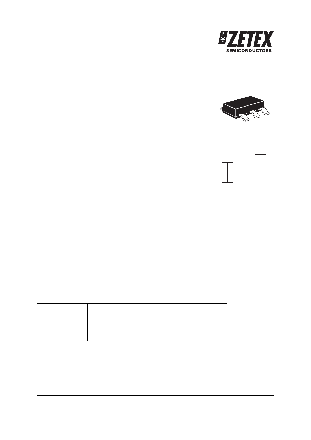
The tab is connected to the drain pin, and must
be electrically isolated from the source pin.
Connection of significant copper to the tab is
recommended for best thermal performance.
SOT223
S
D
D
IN
• Load dump protection (actively protects load)
• Logic level input
Ordering information
Device Reel size
(inches)
BSP75GTA 7 12mm embossed 1,000
BSP75GTC 13 12mm embossed 4,000
Tape width
(mm)
Quantity per reel
Device marking
BSP75G
Issue 4 - May 2006 1 www.zetex.com
© Zetex Semiconductors plc 2006
Page 2
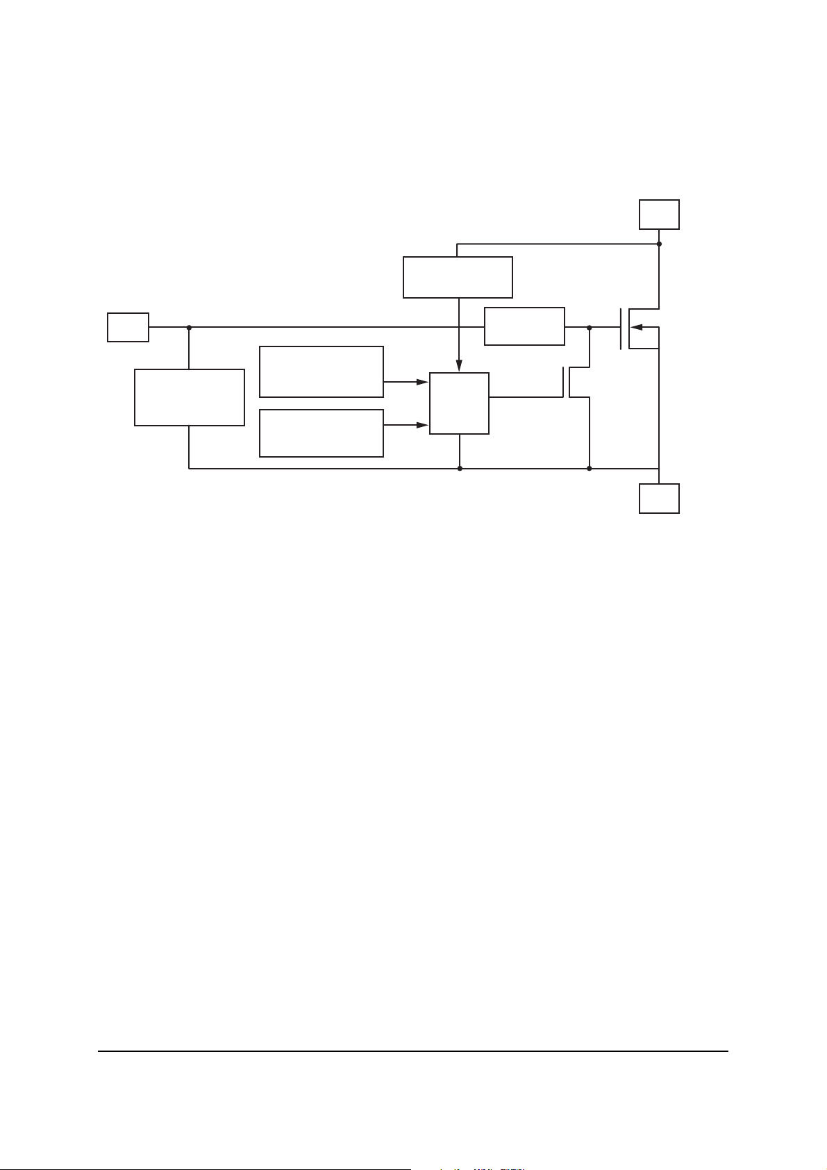
Functional block diagram
Over voltage
protection
BSP75G
D
IN
Human body
ESD protection
Over current
protection
Over temperature
protection
Logic
dV/dt
limitation
S
Applications
• Especially suited for loads with a high in-rush current such as lamps and motors.
• All types of resistive, inductive and capacitive loads in switching applications.
•
C compatible power switch for 12V and 24V DC applications.
• Automotive rated.
• Replaces electromechanical relays and discrete circuits.
• Linear mode capability - the current-limiting protection circuitry is designed to de-activate at
low Vds, in order not to compromise the load current during normal operation. The design
maximum DC operating current is therefore determined by the thermal capability of the
package/board combination, rather than by the protection circuitry.
Issue 4 - May 2006 2 www.zetex.com
© Zetex Semiconductors plc 2006
Page 3
BSP75G
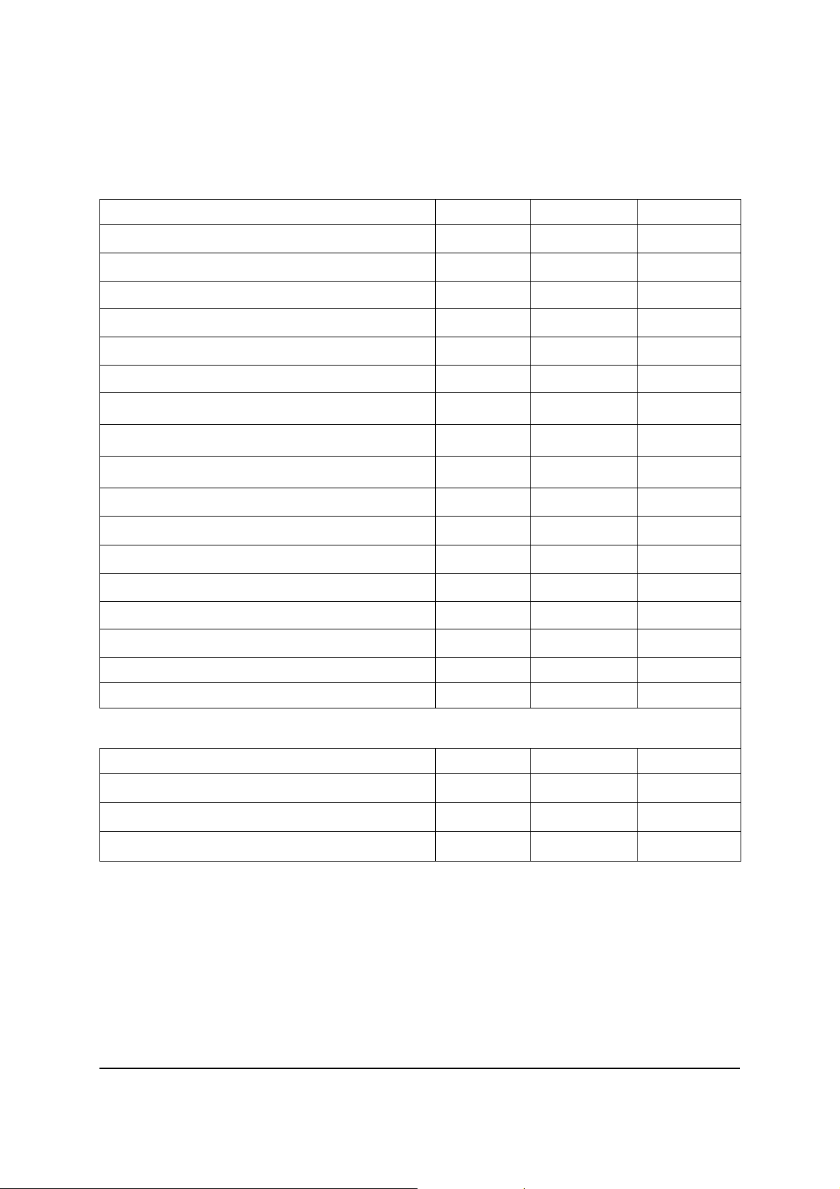
Absolute maximum ratings
Parameter Symbol Limit Unit
Continuous drain-source voltage V
Drain-source voltage for short circuit protection V
DS(SC)
Continuous input voltage V
Peak input voltage V
Operating temperature range T
Storage temperature range T
Power dissipation at T
=25°C
A
Continuous drain current @ V
Continuous drain current @ V
Pulsed drain current @ V
Continuous source current (body diode)
(a)
=10V; TA=25°C
IN
=5V; TA=25°C
IN
=10V I
IN
(a)
(a)
(a)
Pulsed source current (body diode) I
Unclamped single pulse inductive energy E
Load dump protection V
LoadDump
Electrostatic discharge (human body model) V
DS
60 V
36 V
IN
IN
, -40 to +150 °C
j
stg
P
D
I
D
I
D
DM
I
S
S
AS
-0.2 ... +10 V
-0.2 ... +20 V
-55 to +150 °C
2.5 W
1.6 A
1.4 A
5A
3A
5A
550 mJ
80 V
ESD
4000 V
DIN humidity category, DIN 40 040 E
IEC climatic category, DIN IEC 68-1 40/150/56
Thermal resistance
Parameter Symbol Limit Unit
Junction to ambient
Junction to ambient
Junction to ambient
NOTES:
(a) For a device surface mounted on 37mm x 37mm x 1.6mm FR4 board with a high coverage of single sided 2oz weight
copper.
(b) For a device surface mounted on FR4 board and measured at t<=10s.
(c) For a device mounted on FR4 board with the minimum copper required for electrical connections.
(a)
(b)
(c)
R
R
R
⍜JA
⍜JA
⍜JA
50 °C/W
24 °C/W
208 °C/W
Issue 4 - May 2006 3 www.zetex.com
© Zetex Semiconductors plc 2006
Page 4
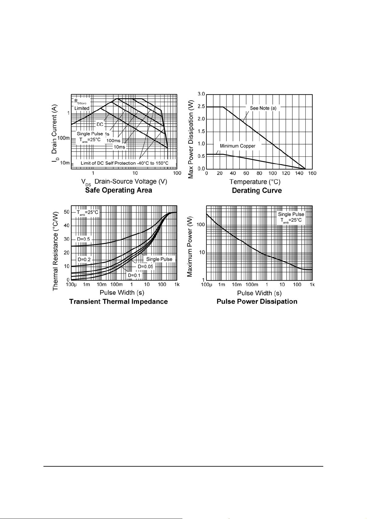
Characteristics
BSP75G
Issue 4 - May 2006 4 www.zetex.com
© Zetex Semiconductors plc 2006
Page 5
BSP75G
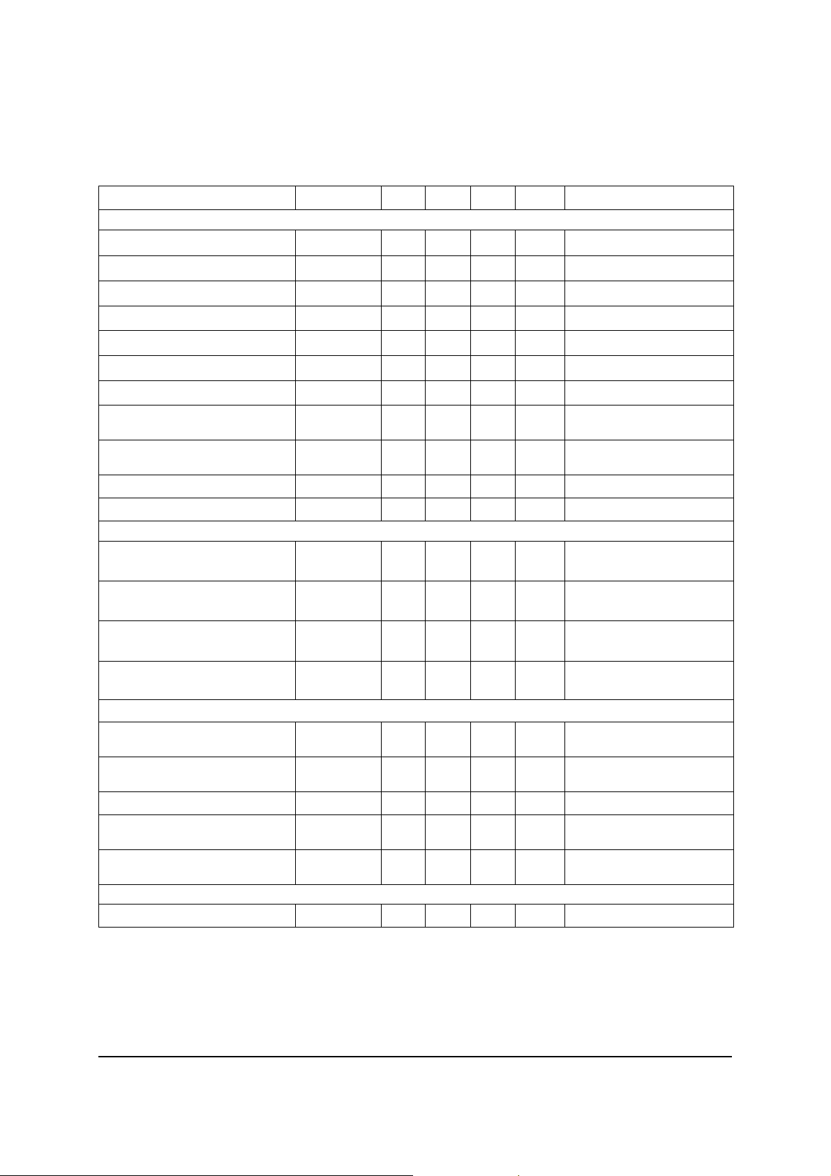
Electrical characteristics (at Tamb = 25°C unless otherwise stated)
Parameter Symbol Min. Typ. Max. Unit Conditions
Static characteristics
Drain-source clamp voltage V
Off-state drain current I
Off-state drain current I
Input threshold voltage
(*)
Input current I
Input current I
Input current I
Static drain-source on-state
DS(AZ)
DSS
DSS
V
IN(th)
R
DS(on)
IN
IN
IN
resistance
Static drain-source on-state
R
DS(on)
resistance
Current limit
Current limit
(†)
(†)
I
D(LIM)
I
D(LIM)
Dynamic characteristics
Turn-on time (V
Turn-off time (V
Slew rate on (70 to 50% V
Slew rate off (50 to 70% V
Protection functions
Required input voltage for
to 90% ID)t
IN
to 90% ID)t
IN
)
DD
)dVDS/dt
DD
(‡)
on
off
-dVDS/dt
V
PROT
over temperature protection
Thermal overload trip
T
JT
temperature
Thermal hysteresis 10 °C
Unclamped single pulse
E
AS
inductive energy Tj=25°C
Unclamped single pulse
E
AS
inductive energy Tj=150°C
Inverse diode
Source drain voltage V
NOTES:
(*) Protection features may operate outside spec for V
(†) The drain current is limited to a reduced value when V
(‡) Integrated protection functions are designed to prevent IC destruction under fault conditions described in the
datasheet. Fault conditions are considered as "outside" normal operating range. Protection functions are not designed
for continuous, repetitive operation.
SD
60 70 75 V ID=10mA
0.1 3 A V
315A V
=12V, VIN=0V
DS
=32V, VIN=0V
DS
12.1 VVDS=VGS, ID=1mA
0.7 1.2 mA VIN=+5V
1.5 2.7 mA VIN=+7V
47mAVIN=+10V
520 675 m⍀ V
385 550 m⍀ V
=+5V, ID=0.7A
IN
=+10V, ID=0.7A
IN
0.7 1.1 1.75 A VIN=+5V, VDS>5V
234AVIN=+10V, VDS>5V
2.2 10 sRL=22⍀, VDD=12V,
V
=0 to +10V
IN
13 20 sRL=22⍀, VDD=12V,
=+10V to 0V
V
IN
on
off
10 20 V/sRL=22⍀, VDD=12V,
=0 to +10V
V
IN
3.2 10 V/s R
=22⍀, VDD=12V,
L
=+10V to 0V
V
IN
4.5 V
150 175 °C
550 mJ I
200 mJ I
D(ISO)
D(ISO)
1VIN=0V, -ID=1.4A
<4.5V.
IN
exceeds a safe level.
DS
=0.7A, VDD=32V
=0.7A, VDD=32V
Issue 4 - May 2006 5 www.zetex.com
© Zetex Semiconductors plc 2006
Page 6
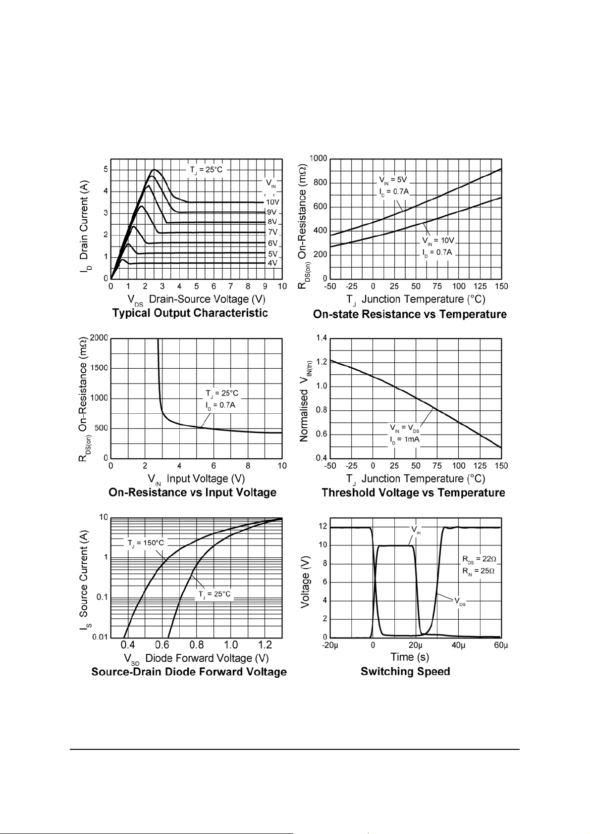
Characteristics
BSP75G
Issue 4 - May 2006 6 www.zetex.com
© Zetex Semiconductors plc 2006
Page 7

BSP75G
Intentionally left blank
Issue 4 - May 2006 7 www.zetex.com
© Zetex Semiconductors plc 2006
Page 8
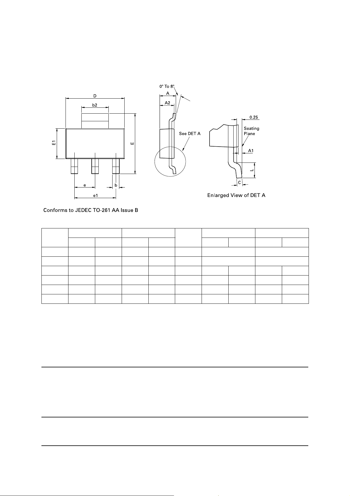
Package outline - SOT223
BSP75G
Dim. Millimeters Inches Dim. Millimeters Inches
Min. Max. Min. Max. Min. Max. Min. Max.
A - 1.80 - 0.071 e 2.30 BSC 0.0905 BSC
A1 0.02 0.10 0.0008 0.004 e1 4.60 BSC 0.181 BSC
b 0.66 0.84 0.026 0.033 E 6.70 7.30 0.264 0.287
b2 2.90 3.10 0.114 0.122 E1 3.30 3.70 0.130 0.146
C 0.23 0.33 0.009 0.013 L 0.90 - 0.355 -
D 6.30 6.70 0.248 0.264 - - - - -
Note: Controlling dimensions are in millimeters. Approximate dimensions are provided in inches
Europe
Zetex GmbH
Streitfeldstraße 19
D-81673 München
Germany
Telefon: (49) 89 45 49 49 0
Fax: (49) 89 45 49 49 49
[email protected]
Americas
Zetex Inc
700 Veterans Memorial Highway
Hauppauge, NY 11788
USA
Telephone: (1) 631 360 2222
Fax: (1) 631 360 8222
[email protected]
Asia Pacific
Zetex (Asia Ltd)
3701-04 Metroplaza Tower 1
Hing Fong Road, Kwai Fong
Hong Kong
Telephone: (852) 26100 611
Fax: (852) 24250 494
[email protected]
Corporate Headquarters
Zetex Semiconductors plc
Zetex Technology Park, Chadderton
Oldham, OL9 9LL
United Kingdom
Telephone: (44) 161 622 4444
Fax: (44) 161 622 4446
[email protected]
These offices are supported by agents and distributors in major countries world-wide.
This publication is issued to provide outline information only which (unless agreed by the company in writing) may not be used, applied or
reproduced for any purpose or form part of any order or contact or be regarded as a representation relating to the products or services concerned.
The company reserves the right to alter without notice the specification, design, price or conditions of supply of any product or service.
Issue 4 - May 2006 8 www.zetex.com
© Zetex Semiconductors plc 2006
 Loading...