

Page 1
APM8600
SINGLE CELL LINEAR LITHIUM BATTERY CHARGER
WITH 28V OVP AND PROGRAMMABLE CHARGE TIMER
Description
The APM8600 is a linear Li-Ion charger for portable
equipment that is optimized for small form-factor
applications.
The charge algorithm in the APM8600 covers all the charge
requirements for a single Li-Ion battery cell. Included is precharging for deeply discharged cells, constant current /
constant voltage fast charging and a top-off feature to bring
the cell safely to a full-charge level.
The battery is constantly monitored for overvoltage, charge
time and cell temperature to ensure safe charging. A fault is
triggered once the charge time exceeds a value that is
programmable using a single capacitor and the temper ature
measurement is achieved through a thermistor positioned
close to the battery cell.
The APM8600 is packaged in U-DFN3030-14 package with
a thermal pad.
Applications
NEW PRODUCT
• Handheld Consumer Devices
• Cell Phones, PDAs, MP3 Players
• Handheld Test Equipment
• Digital Still Cameras
• Multimedia players
Pin Assignments
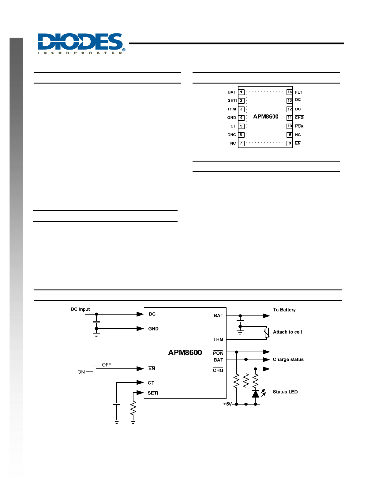
Figure 1 Pin Out
Features
• Linear Lithium Ion / Lithium Polymer charging IC
• Supply input safe up to 28V
• Fast charging with maximum current of 1A
• Resistor-programmable charging current
• Resistor programmable end-of-charge
• Capacitor programmable charge timer
• Three charge indicator pins for a status display
• Thermal protection
• DFN3030-14: Available in “Green” Molding Compound
(No Br, Sb)
• Lead Free Finish/ RoHS Compliant (Note 1)
Note: 1. EU Directive 2002/95/EC (RoHS). All applicable RoHS
exemptions applied. Please visit our website at
http://www.diodes.com/products/lead_free.html
.
Typical Application Circuit
APM8600
Document number: DS35140 Rev. 1 - 2
Figure 2. Typical Application Circuit
1 of 14
www.diodes.com
December 2010
© Diodes Incorporated
Page 2
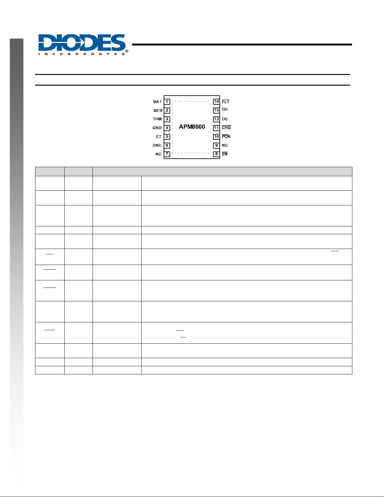
Pin Descriptions
APM8600
SINGLE CELL LINEAR LITHIUM BATTERY CHARGER
WITH 28V OVP AND PROGRAMMABLE CHARGE TIMER
NEW PRODUCT
Name Pin # Description
BAT 1, 7
SETI 2
THM 3 Thermistor Input
GND 4 Ground Ground connection.
CT 5 Charge Timing
EN
10
POK
11
CHG
DC 12, 13 DC Input
FLT
EP Exposed Pad
NC 7,9 Not Connected Floating pins
DNC 6 Do Not Connect Must not connect
14
Connection to the
Charge Current
8
Charge Status
Battery
programming
Enable
(active-low)
Power OK
(active-low)
(active-low)
Fault Flag
(active-low)
The battery is charged via this pin and the BAT voltage is constantly monitored.
Connect a bypass capacitor between BAT and GND (2.2µF).
The maximum charge current is programmed using a resistor from SETI to GND.
This also determines the prequal current charging level and top-off threshold.
To monitor the battery temperature, connect a 10kΩ NTC thermistor. Place this
thermistor as close as possible to the battery. Connect THM to GND if
temperature measurement is not required.
Connecting a capacitor from CT to GND will set the time-outs for prequal, top-off
and fast-charge. Connecting CT direct to GND disables these timers.
The charger is enabled when this input is low. To start the charger connect
GND. Drive this input high to disable the charger.
When a valid input source is connected, this open-drain output is pulled low.
Open-drain output that indicates the charging status. It is active only in the fast-
charge state and goes high-impedance when the charger is either disabled or in
prequal or top-off mode.
DC supply input. The recommended input voltage is between 4.32V and 7V. This
input is capable of withstanding up to 28V. Connect both DC pins together on the
PCB. It is recommended to connect a bypass capacitor (1µF) from DC to GND.
If the prequal or fast-charge timers expire and the charging threshold voltage is
not reached,
power or raise
For optimal thermal performance connect to copper on PCB (electrically this can
be GND).
(open-drain output) will go low. Remove the fault by cycling
FLT
.
EN
to
EN
APM8600
Document number: DS35140 Rev. 1 - 2
2 of 14
www.diodes.com
December 2010
© Diodes Incorporated
Page 3
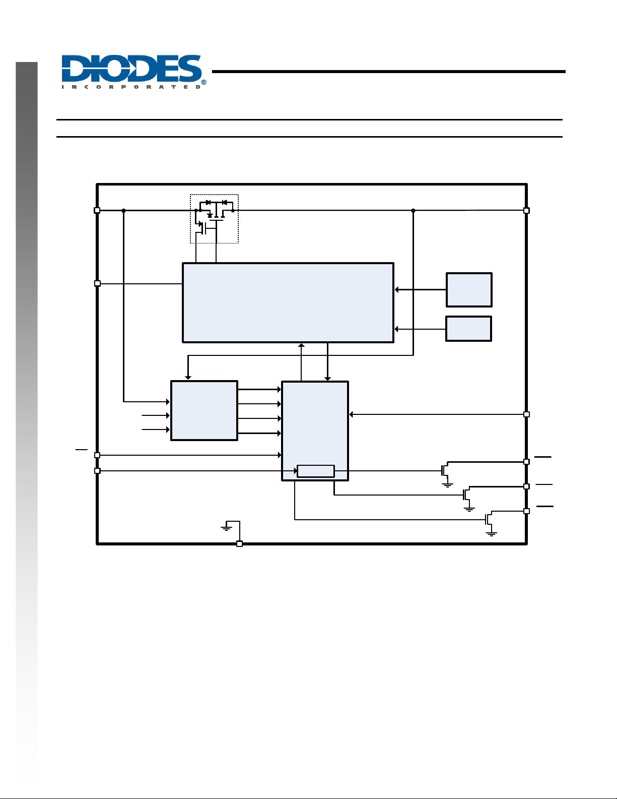
Functional Block Diagram
APM8600
SINGLE CELL LINEAR LITHIUM BATTERY CHARGER
WITH 28V OVP AND PROGRAMMABLE CHARGE TIMER
NEW PRODUCT
DC
SETI
EN
CT
3.0V
4.2V
CHARGE
CONDITION
COMPARATORS
CHARGER REGULATOR
OVLO
UVLO
V
DROP
PREQUAL
CHARGE
CONTROL
TIMER
THERMAL
CURRENT
FOLDBACK
PROTECTION
1.5V
REFERENCE
BAT
THM
FLT
POR
APM8600
Document number: DS35140 Rev. 1 - 2
GND
3 of 14
www.diodes.com
CHG
December 2010
© Diodes Incorporated
Page 4
APM8600
SINGLE CELL LINEAR LITHIUM BATTERY CHARGER
WITH 28V OVP AND PROGRAMMABLE CHARGE TIMER
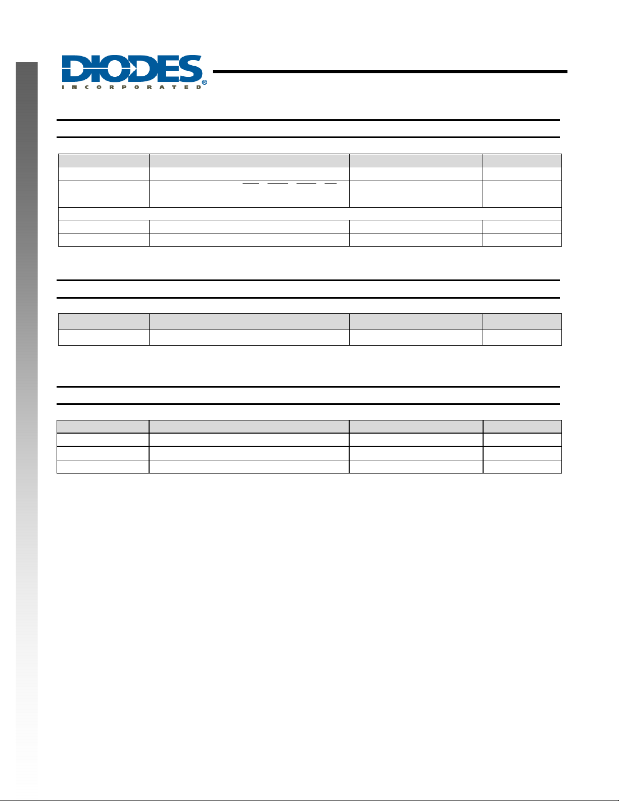
Absolute Maximum Ratings
Symbol Parameter Rating Unit
DC to GND -0.3 to 28V V
ESD Susceptibility (Note 2)
HBM Human Body Model 2 kV
MM Machine Model 200 V
Note: 2. Semiconductor devices are ESD sensitive and may be damaged by exposure to ESD events. Suitable ESD precautions should be
taken when handling and transporting this device.
BAT, CT, SETI, THM,
to GND -0.3 to 6V
FLT
,
CHG, POK
Thermal Resistance (Note 3)
Symbol Parameter Rating Unit
θ
Junction to Ambient 40 °C/W
JA
Note: 3. Test condition for DFN3030-10: Device mounted on FR-4 2-layer board, 2oz copper, with minimum recommended pad on top layer and 6 vias to
bottom layer 1.0”x1.5” ground plane.
NEW PRODUCT
, EN
V
Recommended Operating Conditions (Note 4)
Symbol Parameter Rating Unit
Ambient Temperature Range -40 to +85 °C
I
Typical Charge Current 0.1 to 1.0 A
CHARGE
Note: 4. The device function is not guaranteed outside of the recommended operating conditions.
Input Supply Voltage
4.15 to 7.00
V
APM8600
Document number: DS35140 Rev. 1 - 2
4 of 14
www.diodes.com
December 2010
© Diodes Incorporated
Page 5
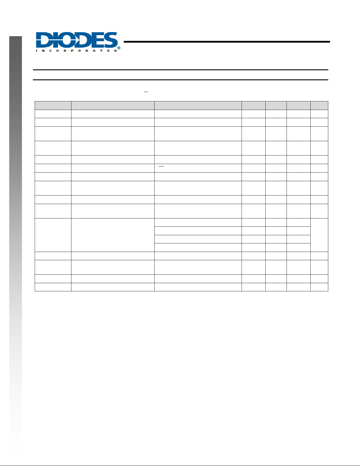
Electrical Characteristics
APM8600 is tested at VDC = 5V, V
otherwise noted.
Symbol Parameter Test Conditions Min Typ. Max Unit
NEW PRODUCT
V
DC
V
DC
UVLO
OVLO Input Overvoltage Lock Out
IDC Input Supply Current I
I
SHTDWN
R
DS_ON
V
DROPOUT
V
BAT_REG
BAT
RSTTH
I
DC_CHG
SS Soft-Start Time Ramp time to fast-charge 1.2 ms
V
PREQ_TH
I
LEAK
R
SETI
Note: 5. Guaranteed by testing of undervoltage- and overvoltage-threshold. To completely charge a battery cell, the input voltage must be greater than 4.32V.
Input Voltage Range 0 28 V
Input Operating Range (Note 5) 4.15 7.00 V
Input Undervoltage Lock Out
(Note 5)
Shutdown Current
Input to BAT On-Resistance Input = 3.7V, V
Input to BAT dropout Voltage
Battery Voltage Regulation I
Battery Fast-Charge Restart
Threshold
DC Charge Current
V
USB
BAT Prequel Threshold
BAT Leakage Current VDC = V
Resista nce Ra nge for SETI Guaranteed by charging current 1.5 5.0 kΩ
= 0V
WITH 28V OVP AND PROGRAMMABLE CHARGE TIMER
= 4V, VEN = 0V, R
BAT
APM8600
SINGLE CELL LINEAR LITHIUM BATTERY CHARGER
= 2kΩ, CCT = 68nF, at an ambient temperature of +25°C unless
SETI
Input rising, 500mV hysteresis
BAT
= 3.2V
(typ.) V
Input rising, 200mV hysteresis
(typ.)
= 0mA, R
BAT
= High, TA = 25ºC
EN
= 10kΩ 750 1200 µA
THM
= 3.6V 0.5 0.8 Ω
BAT
Input falling, 200mV hysteresis
(typ.)
= 0mA, TA = 25ºC 4.179 4.2 4.221 V
BAT
From BAT regulation voltage -230 -175 -110 mV
R
= 1.5kΩ 950 1000 1140
SETI
R
= 2.0kΩ 727 750 870
SETI
R
= 5.0kΩ 280 300 353
SETI
Prequal, R
V
rising, 180mV hysteresis
BAT
= 2kΩ, V
SETI
= 2.5V 60 75 95
BAT
(typ.)
USB
= 0V, V
= 4.2V 0.001 5 µA
BAT
3.85 4.0 4.15 V
7.2 7.5 7.8 V
275 435 µA
5 55 150 mV
mA
2.9 3.0 3.1 V
APM8600
Document number: DS35140 Rev. 1 - 2
5 of 14
www.diodes.com
December 2010
© Diodes Incorporated
Page 6
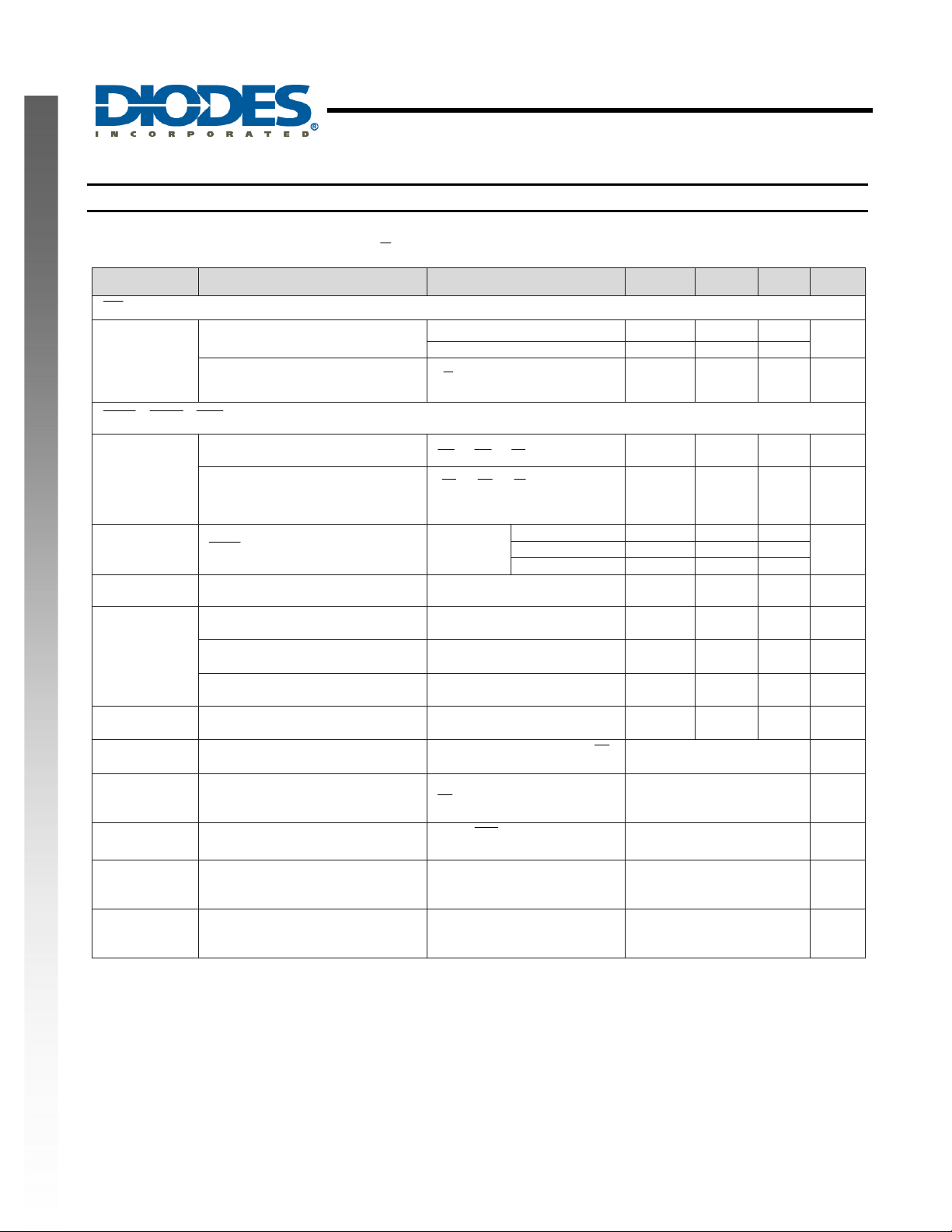
Electrical Characteristics (Continued)
APM8600 is tested at VDC = 5V, V
otherwise noted.
Symbol Parameter Test Conditions Min Typ. Max Unit
EN
Logic Input Thresholds
Logic Input Leakage Current
POK , CHG, FLT
Logic Output Voltage, Low
Logic Output Leakage Current,
High
I
NEW PRODUCT
TOPOFF
R
THM_Pullup
Internal Pullup Resistance 10 kΩ
THM Resistance, Hot
R
THM
THM Resistance, Cold
THM Resistance, Disabled
CT
Charge Timer Accuracy CCT = 68nF -20 +20 %
accu
TL
TL
THFB
THFB
Prequal Time Limit
Prequal
TL
Charge Time Limit
CHG
Top-Off Time Limit
Top_off
Thermal Foldback Threshold
temp
Gain
Temperature
Thermal Foldback Gain
/ Top-Off Threshold
CHG
BAT
SINGLE CELL LINEAR LITHIUM BATTERY CHARGER
WITH 28V OVP AND PROGRAMMABLE CHARGE TIMER
= 4V, VEN = 0V, R
APM8600
= 2kΩ, CCT = 68nF, at an ambient temperature of +25°C unless
SETI
Rising 1.6
Falling 0.4
V
= 0 to 5.5V,
EN
T
= 25ºC
A
1mAIII
===
FLTCHGPOK
V
= V
USB
falling,
= 0V
DC
= +25°C
T
A
I
BAT
battery is
charged
R
falling, 420Ω hyst.
THM
FLTCHGPOK
R
R
R
5.5VVVV
===
= 1.5kΩ 75
SETI
= 2.0kΩ 37.5 56.25 75
SETI
= 5.0kΩ 22.5
SETI
(typ.)
rising, 2.7kΩ hyst.
R
THM
(typ.)
falling, 230Ω hyst.
R
THM
(typ.)
From entering prequal to
going low, V
BAT
< 3V
FLT
0.001 1 µA
12 100 mV
0.001 1 µA
3.72 3.94 4.13 kΩ
26.7 28.3 29.7 kΩ
260 315 370 Ω
34.8 min
From entering fast-charge to
going low, 3V < V
FLT
BAT
<
334 min
4.2V
From
charger disabled
going high to
CHG
34.8 min
Junction temperature beyond
which the charge current is
reduced, T
Reduction of I
increase in T
R
SETI
rising
J
= 1.5kΩ
for
BAT
(using VDC),
J
+100 ºC
5 %/ºC
V
mA
APM8600
Document number: DS35140 Rev. 1 - 2
6 of 14
www.diodes.com
December 2010
© Diodes Incorporated
Page 7
APM8600
A
A
A
A
A
A
A
A
A
SINGLE CELL LINEAR LITHIUM BATTERY CHARGER
WITH 28V OVP AND PROGRAMMABLE CHARGE TIMER
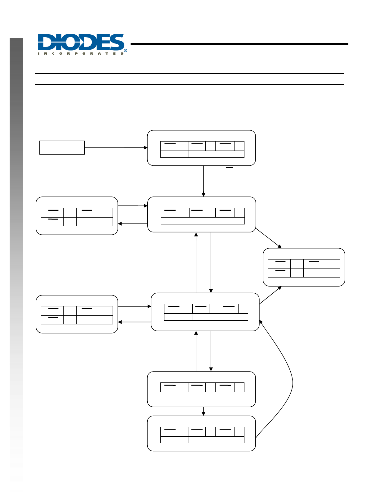
Functional Description
APM8600 is a linear Li-Ion battery charger device for single-cell applications. Charg e currents can be programm ed with the
R
resistor. The device also incorporates several safety features, such as charge timers, battery temperature monitoring
SETI
and internal thermal limiting.
Functional State Diagram
NEW PRODUCT
EN = HIGH
ANY STATE
OR V
OR V
OR V
< V
IN
< 4.0V
IN
> 7.5V
IN
THM
POK 0 FLT 1
CHG 1 I
Timer Hold
BAT
0A
THM
POK 0 FLT 1
CHG 0 I
Timer Hold
BAT
0A
BAT
R
OR (R
ND R
(R
ND R
OR R
R
OR (R
ND R
(R
ND R
OR R
< 315Ω
THM
THM
< 28.3kΩ)
THM
THM
< 3.94kΩ)
THM
> 28.3kΩ
THM
< 315Ω
THM
THM
< 28.3kΩ)
THM
THM
< 3.94kΩ)
THM
> 28.3kΩ
THM
> 3.94kΩ
> 315Ω
> 3.94kΩ
> 315Ω
I
> 172.5 / R
BAT
Reset Timer
DISABLE
POK 1 FLT 1 CHG 1
I
0A
BAT
EN = LOW
ND VIN > V
ND VIN > 4.0V
ND VIN < 7.5V
PREQUAL
POK 0 FLT 1 CHG 1
I
150 / R
BAT
V
< 2.82V
BAT
Reset Timer
SETI
V
> 3V
BAT
Reset Timer
CHARGE
POK 0 FLT 1 CHG 0
I
(DC) 1500 / R
BAT
SETI
I
< 112.5 / R
SETI
BAT
Reset Timer
BAT
SETI
V
< 3V
BAT
ND Time out
FAULT
POK 0 FLT 0
CHG 1 I
BAT
I
> 112.5 / R
BAT
SETI
ND Time out
0A
V
TOP-OFF
BAT
< 4.05V
Reset Timer
POK 0 FLT 1 CHG 1
Time out
DONE
POK 0 FLT 1 CHG 1
I
0A
BAT
APM8600
Document number: DS35140 Rev. 1 - 2
7 of 14
www.diodes.com
December 2010
© Diodes Incorporated
Page 8
APM8600
°
SINGLE CELL LINEAR LITHIUM BATTERY CHARGER
WITH 28V OVP AND PROGRAMMABLE CHARGE TIMER
Functional Description (continued)
INPUTS
DC Pins 12 and 13 are the DC input. This input will allow chargin g from input voltages bet ween 4.15V and 7V, and ca n
withstand up to 28V without device damage although charging is disabled above 7.5V (typ.).
GND System ground connecti on.
EN Pin 8 is the enable pin of the device. When pulled low the device will operate normally. W hen high, the device will
remain in the disabled state. For auto-starting, connect pin 8 directly to GND.
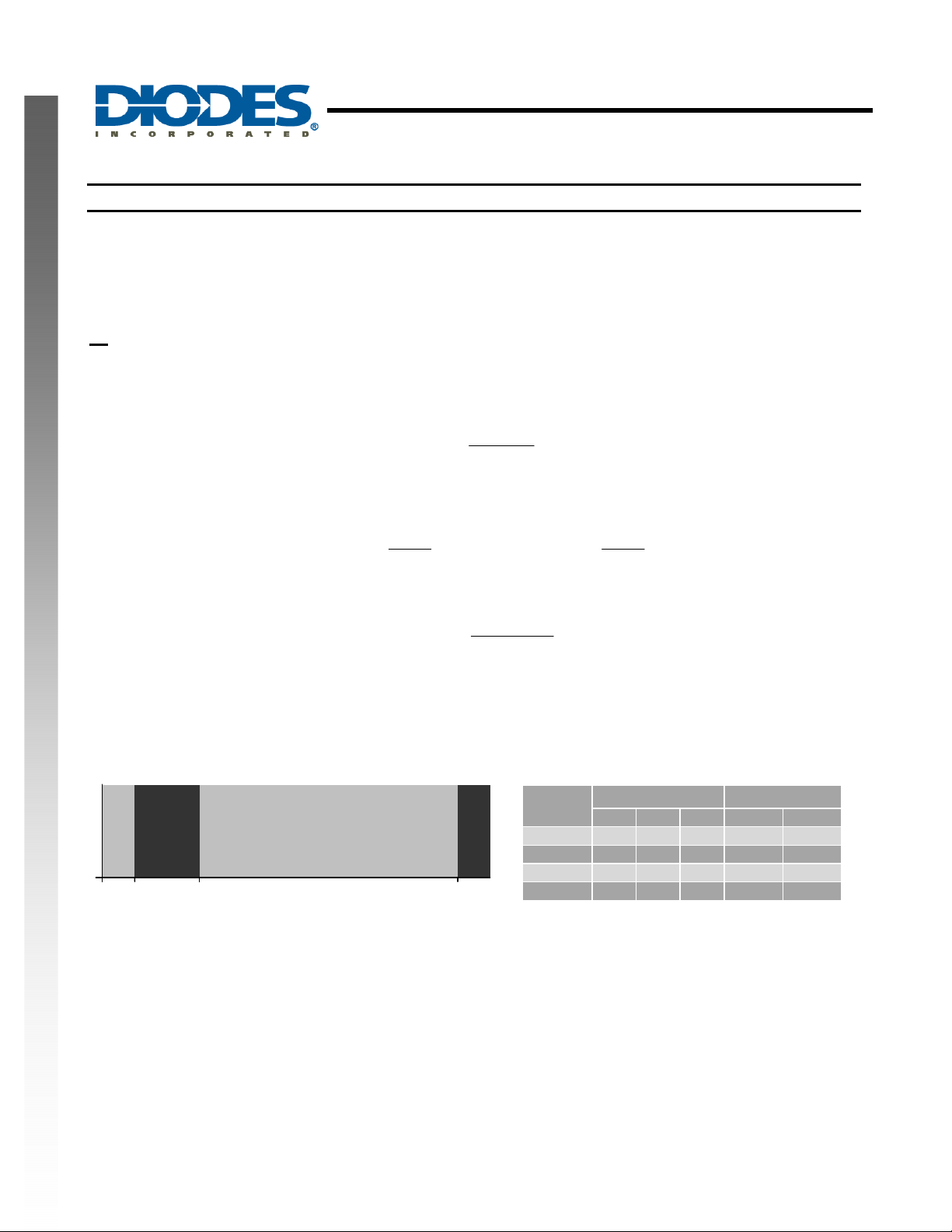
SETI Pin 2 allows the charge currents to be programmed.
RSETI =
1500
ICHARGE
The charge current setting also changes the currents in prequal and top- off modes (being 10% an d 7.5% of I
respectively):
150
NEW PRODUCT
IPREQUAL =
RSETI
This pin can also be used to monitor the bat tery charging current:
ICHARGE×=
THM The thermistor connection is on pin 3. This allows the battery temperature to be monitored using a 10k NTC
thermistor, which should be placed as close as possible to the batte ry cell. If no thermistor is used then this inp ut should be
connected directly to ground. The charger will operate when there is less than 315Ω on this input (i.e., no thermistor
connected); will be disabled when there is between 315Ω and 3.94k Ω; enabled when between 3.94kΩ and 28.3kΩ; and
disabled above 28.3kΩ.
R
THM
Enabled
Disabled
Enabled
0 315Ω 3.94k 28.3k
Disabled
RSETI
112.5
ITOPOFF =
1000VSETI
Beta
3000 25.1 10 4. 6 55.1 ‐3.2
3250 27.1 10 4. 3 52.6 ‐1.3
3500 29.3 10 4 50.5 0.5
3750 31.7 10 3. 8 48.6 2.0
RSETI
ResistanceinkΩat Typicalin
0°C 25°C 50°C Hot trip ColdTrip
CHARGE
CThermistor
APM8600
Document number: DS35140 Rev. 1 - 2
8 of 14
www.diodes.com
December 2010
© Diodes Incorporated
Page 9

APM8600
SINGLE CELL LINEAR LITHIUM BATTERY CHARGER
WITH 28V OVP AND PROGRAMMABLE CHARGE TIMER
Functional Description (continued)
CT The Charge Timer input on pin 5 allows sel ection of how long the system timers for Prequal, Charge and T op-off
states last. They are set by selecting the value of capacit or, C
The charge timer will hold its current value if the charging was stopped vi a the thermistor and continue when the battery is in
a valid temperature range for charging.
OUTPUTS
BAT Pin 1 is the current-controlled charg ing output for the bat tery cell. It should be connected to the positive t erminal of
the battery. The chip monitors the voltage on this pin. There should be a 2.2µF capacitor connected from BAT to GND.
POK The POK flag on pin 10 is pulled low when a valid power input is available on D C. It will go high when no valid
power is available and the device will enter the Dis able state.
CHG The CHG flag at pin 11 is pulled low when the device is in the Charge state. It will be high in Prequa l and Top-off
NEW PRODUCT
states. If the thermistor trips the circuit into the THM state (from Prequal or Charge states),
FLT The F LT flag on pin 14 indic ates a batter y fault, as det ermined by a time- out in either th e Prequal or Charge st ates.
If the battery voltage does not reach 3V after the prequal timer (default 34. 8mins), or does not reduce charging current to
7.5% after the charge timer (default 334mins), this indicates that the battery has failed or is failing and this will trigger the
FLT flag. This flag will not automatically reset, and can only be cleared by cycling the power input or the EN pin.
:
CT
⎛
×=
min334TCHARGE
⎜
⎝
CCT
⎞
⎟
nF68
⎠
CCT
⎛
min34.8TTOPOFFTPREQUAL
×==
⎜
nF68
⎝
⎞
⎟
⎠
CHG will hold its previous value.
APM8600
Document number: DS35140 Rev. 1 - 2
9 of 14
www.diodes.com
December 2010
© Diodes Incorporated
Page 10
WITH 28V OVP AND PROGRAMMABLE CHARGE TIMER
Functional Description (continued)
EN
CHG
V
BAT
0V
APM8600
SINGLE CELL LINEAR LITHIUM BATTERY CHARGER
4.2V
3V
I
CHARGE
1500/R
SETI
NEW PRODUCT
I
BAT
DISABLE
I
PREQUAL
150/R
0A
PREQUAL
SETI
CHARGE
I
TOPOFF
112.5/R
SETI
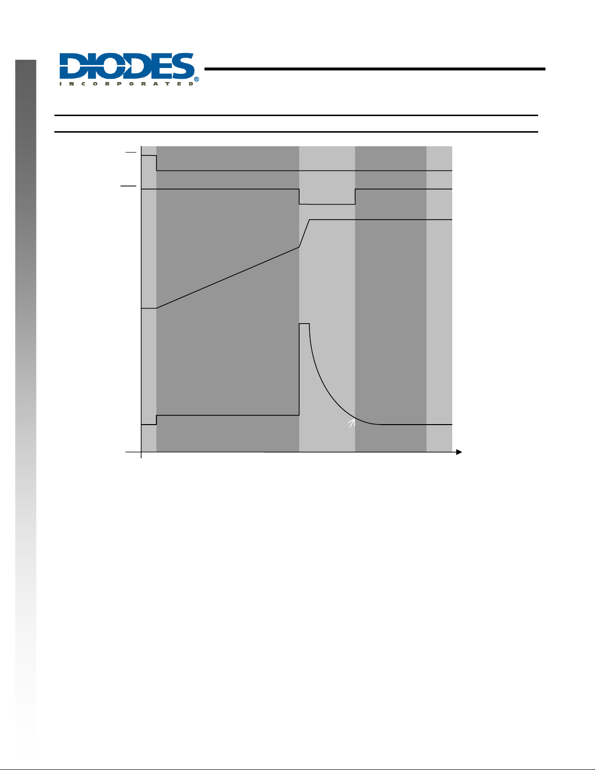
CHARGING PROCESS DESCRIPTION
The charging process is as follows, working through the state dia gram.
The device will begin in the
Disable state as the input power supply ramps from 0V. Once the input power sup ply has got
into the valid range (4.15V – 7V), and the device is enabled then it will enter the
charging of a severely discharged battery. If the battery is already partially charged then the condition to move into the
Charge state is met. If it is not then the slow charge will increase the battery voltage unti l it can enter the Charge state, or if
the voltage does not rise sufficiently befor e the ch arge time r runs out (set using the c apa citor on th e CT pin) then th e device
will go into the
Fault state, indicating that the battery cell may be damag ed or has failed and is not taking charge. In the
Prequal state the battery temperature can be monitored with a 10k NTC thermistor connected to the T HM pin, and if the
battery temperature goes out of range (above ~50°C or belo w ~0°C, depending on thermistor choice) then chargi ng will be
suspended with the device going into the
THM state.
Once the battery has charged to a level of 3V, the device enters the
its normal voltage range, with 10 times the current used in the
Charge state, allowing faster charging of the battery in
Prequal state. For information on setting the charge currents,
see the functional description of the SETI pin. Again, the battery temperature is monitored and charg ing will be suspe nded if
the temperature goes out of range. T he
charge current. The device will then enter the
current for the time defined by the C
Charge state will last until the current drawn by the battery drops to 7.5% of the full
Top-Off state, maintaining battery voltage and providing top-off charging
value. Once that timer completes, the device will enter the Done state, with zero
T
battery current. If the battery voltage falls b elow 4.05V then the device will automatically return to the
TOP-OFF
DONE
t
Prequal state. This state allows for slow
Charge state.
APM8600
Document number: DS35140 Rev. 1 - 2
10 of 14
www.diodes.com
December 2010
© Diodes Incorporated
Page 11
Ordering Information
APM8600
SINGLE CELL LINEAR LITHIUM BATTERY CHARGER
WITH 28V OVP AND PROGRAMMABLE CHARGE TIMER
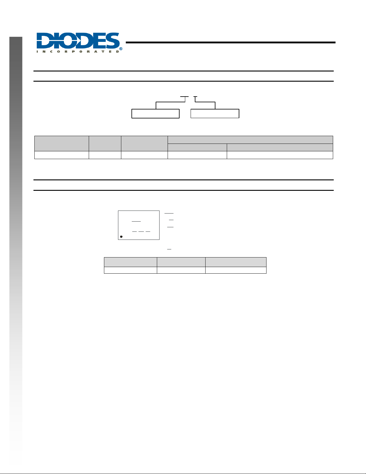
APM8600 FB - 7
Package
FB :U-DFN3030-14
Device
APM8600FB-7 FB U-DFN3030-14 3000/Tape & Reel -7
Note: 6. Pad layout as shown on Diodes Inc. suggested pad layout document AP02001, which can be found on our website at
http://www.diodes.com/datasheets/ap02001.pdf.
Package
Code
Packaging
(Note 6)
Quantity Part Number Suffix
Packing
7 : Tape & Reel
7” Tape and Reel
Marking Information
( Top View )
: P3 : APM8600
NEW PRODUCT
XX
X
Y
W
Part Number Package Identification Code
APM8600FB-7 U-DFN3030-14 P3
XX
: Year : 0~9
Y
W
: Week : A~Z : 1~26 week;
a~z : 27~52 week;
z : represents 52 and 53
X
: A~Z : Internal Code
APM8600
Document number: DS35140 Rev. 1 - 2
11 of 14
www.diodes.com
December 2010
© Diodes Incorporated
Page 12
SINGLE CELL LINEAR LITHIUM BATTERY CHARGER
WITH 28V OVP AND PROGRAMMABLE CHARGE TIMER
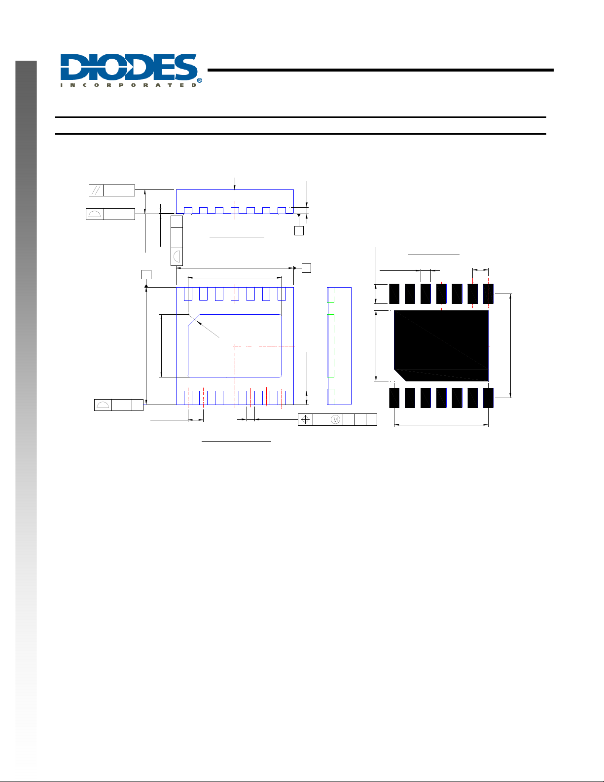
Package Outline Dimensions (All Dimensions in mm)
U-DFN3030-14
TOP MARK
APM8600
NEW PRODUCT
2X-
0.10 C
0.08 C
0.25
0.57/0.63
B
2.95/3.05
B
0/0.05
2X-
1.6/1.8
0.40Typ.
A
Side View
0.25
(Pin #1 ID)
C
0
.
Bottom View
2.95/3.05
2.2/2.4
3
C
L
0.15/0.25
C
A
C
L
0.15
Seating Plane
0.30/0.40
0.10
C
AB
Top View
14x-0.25
14x-0.50
1.80
(Pin #1 ID)
Land Pattern Recommendation
C
L
2.40
(Unit:mm)
0.40Typ
C
L
2.65
APM8600
Document number: DS35140 Rev. 1 - 2
12 of 14
www.diodes.com
December 2010
© Diodes Incorporated
Page 13
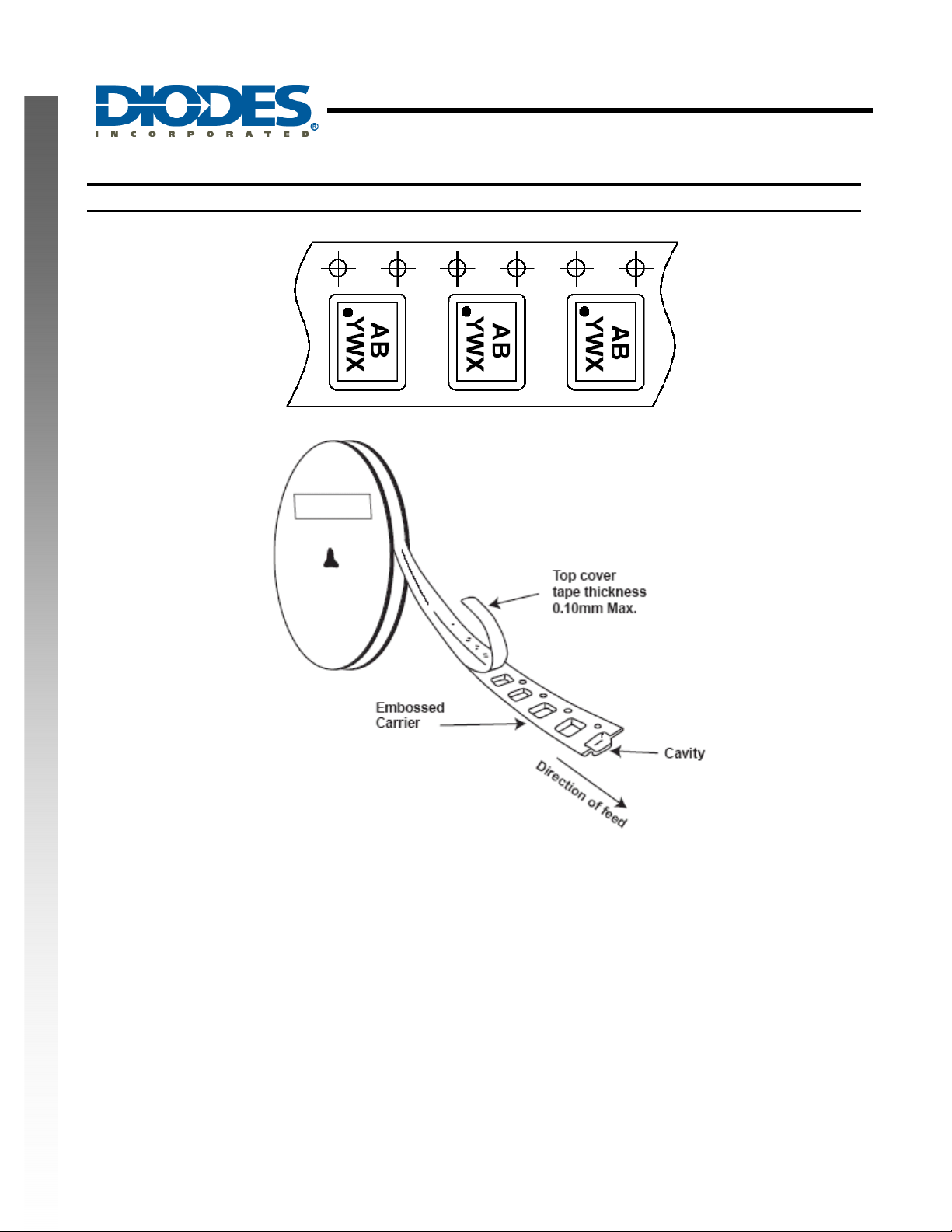
Taping Orientation (Note 6)
APM8600
SINGLE CELL LINEAR LITHIUM BATTERY CHARGER
WITH 28V OVP AND PROGRAMMABLE CHARGE TIMER
NEW PRODUCT
Note: 6. The taping orientation of the other package type can be found on our website at http://www.diodes.com/datasheets/ap02007.pdf
APM8600
Document number: DS35140 Rev. 1 - 2
13 of 14
www.diodes.com
December 2010
© Diodes Incorporated
Page 14

APM8600
SINGLE CELL LINEAR LITHIUM BATTERY CHARGER
WITH 28V OVP AND PROGRAMMABLE CHARGE TIMER
NEW PRODUCT
IMPORTANT NOTICE
DIODES INCORPORATED MAKES NO WARRANTY OF ANY KIND, EXPRESS OR IMPLIED, WITH REGARDS TO THIS
DOCUMENT, INCLUDING, BUT NOT LIMITED TO, THE IMPLIED WARRANTIES OF MERCHANTABILITY AND FITNESS FOR A
PARTICULAR PURPOSE (AND THEIR EQUIVALENTS UNDER THE LAWS OF ANY JURISDICTION).
Diodes Incorporated and its subsidiaries reserve the right to make modifications, enhancements, improvements, corrections or other
changes without further notice to this document and any product described herein. Diodes Incorporated does not assume any liability
arising out of the application or use of this document or any product described herein; neither does Diodes In corporated convey any
license under its patent or trademark rights, nor the rights of others. Any Customer or user of this documen t or products described
herein in such applications shall assume all risks of such use and will agree to hold Diodes Incorporated and all the companies
whose products are represented on Diodes Incorporated website, harmless against all damages.
Diodes Incorporated does not warrant or accept any liability whatsoever in respect of any products purchased through unauthorized
sales channel.
Should Customers purchase or use Diodes Incorporated products for any unintended or unauthorized application, Customers shall
indemnify and hold Diodes Incorporated and its representatives harmless against all claims, damages, expenses, and attorney fees
arising out of, directly or indirectly, any claim of personal injury or death associated with such unintended or unauthorized application.
Products described herein may be covered by one or more United States, international or foreign p atents pending. Product names
and markings noted herein may also be covered by one or more United States, international or foreign trademarks.
LIFE SUPPORT
Diodes Incorporated products are specifically not authorized for use as critical components in life support devices or systems without
the express written approval of the Chief Executive Officer of Diodes Incorporated. As used herein:
A. Life support devices or systems are devices or systems which:
1. are intended to implant into the body, or
2. support or sustain life and whose failure to perform when properly used in accordance with instructions for use provided
in the labeling can be reasonably expected to result in significant injury to the user.
B. A critical component is any component in a life support device or system whose failure to perform can b e reasonably expected
to cause the failure of the life support device or to affect its safety or effectiveness.
Customers represent that they have all necessary expertise in the safety and regulatory ramifications of their life support dev ices or
systems, and acknowledge and agree that they are solely responsible for all legal, regulatory and safety-related requirements
concerning their products and any use of Diodes Incorporated products in such safety-critical, life support devices or systems,
notwithstanding any devices- or systems-related information or support that may be provided by Diodes Incorporated. Further,
Customers must fully indemnify Diodes Incorporated and its representatives against any damages arising out of the use of Diodes
Incorporated products in such safety-critical, life support devices or systems.
Copyright © 2010, Diodes Incorporated
www.diodes.com
APM8600
Document number: DS35140 Rev. 1 - 2
14 of 14
www.diodes.com
December 2010
© Diodes Incorporated
 Loading...