

Page 1
AP3041EV1 User Guide
Parameter
Value
Input Voltage
IC
12VDC
System
100VDC
LED Current
125mA
Number of LEDs
60 LEDs in series
(Vo=195V)
XYZ Dimension
80mm x 65mm x 18mm
General Description
This demonstration board utilizes the
AP3041 high voltage low-side N-channel
MOSFET controller ideal for boost
regulators. It contains all the features
needed to implement single-ended primary
topology DC/DC converters. The input
voltage of AP3041 ranges from 5V to 27V.
Its operation frequency is adjustable from
100kHz to 1MHz.
The AP3041 has UVLO (Under Voltage Lock
Out) circuit. It uses two external resistors to
set the UVLO voltage. The AP3041 also has
an over output voltage protection to limit
the output voltage. The OVP voltage can be
set through external resistors. If the output
voltage is higher than the OVP high
threshold point, it will disable the driver
and the system is latched up. The output
short circuit protection as well as LED low
side short to ground detection function can
be applied in system.
The AP3041 has other protection functions,
such as LED short protection, LED high side
short to ground protection, diode short
protection, over current protection, over
temperature protection and so on.
Applications
• LED Lighting
• LED TV
• LCD Display Modules
AP3041EV1 Page 1 of 7
May 2014
www.diodes.com
Key Features
Input Voltage Range: 5V to 27V
1A Peak and 10V MOSFET Gate Driver
20ns Quick MOSFET Gate Driver
Duty Cycle Limit of 90%
Programmable UVLO
PWM Dimming Control
Programmable Over Voltage Protection
LED Open Protection
LED Short Circuit Protection
Diode Short Circuit Protection
Output Short Circuit Protection
LED Low-side Short to Ground
Detection
OV Pin Under Voltage Protection
Over Current Protection
Programmable Slope Compensation
Adjustable Soft-start
Adjustable Protection Delay
Fault Status Indication
Adjustable Operation Frequency from
100kHz to 1MHz
Over Temperature Protection
AP3041EV1 Specifications
Page 2
AP3041EV1 User Guide
PVIN
GND
LED+
LED-
PWM
PVIN
GND
LED+
LED-
EN
AVIN
EN
PWM
AVIN
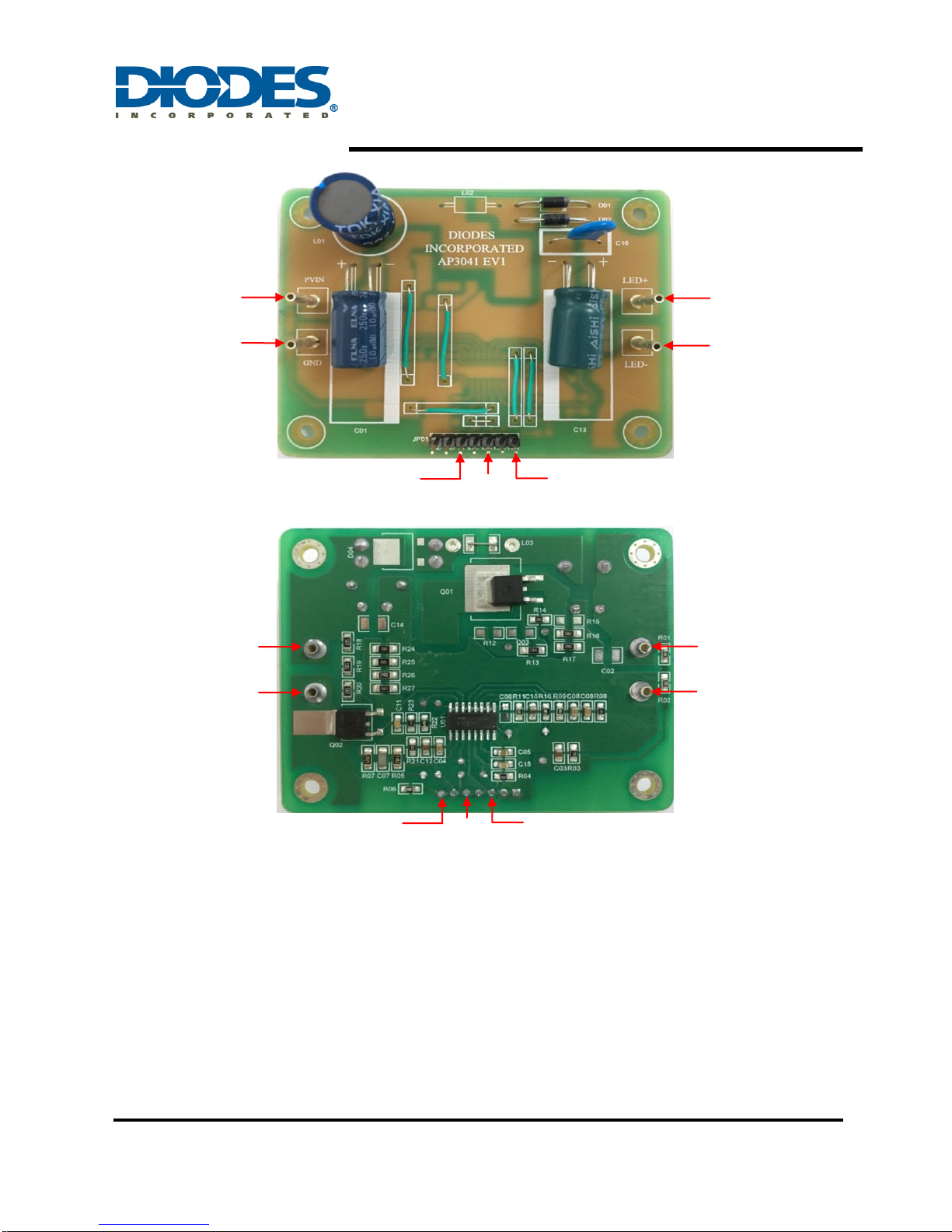
Figure 1: Top View
Connection Instructions
Power Supply Input: 100VDC (PVIN, GND)
IC Power Supply Input: 12VDC (AVIN, GND)
Enable Signal Input: 5VDC (EN, GND)
PWM Signal Input: (PWM, GND)
LED Outputs: LED+ (LED+), LED- (LED-)
AP3041EV1 Page 2 of 7
May 2014
www.diodes.com
Figure 2: Bottom View
Page 3
AP3041EV1 User Guide
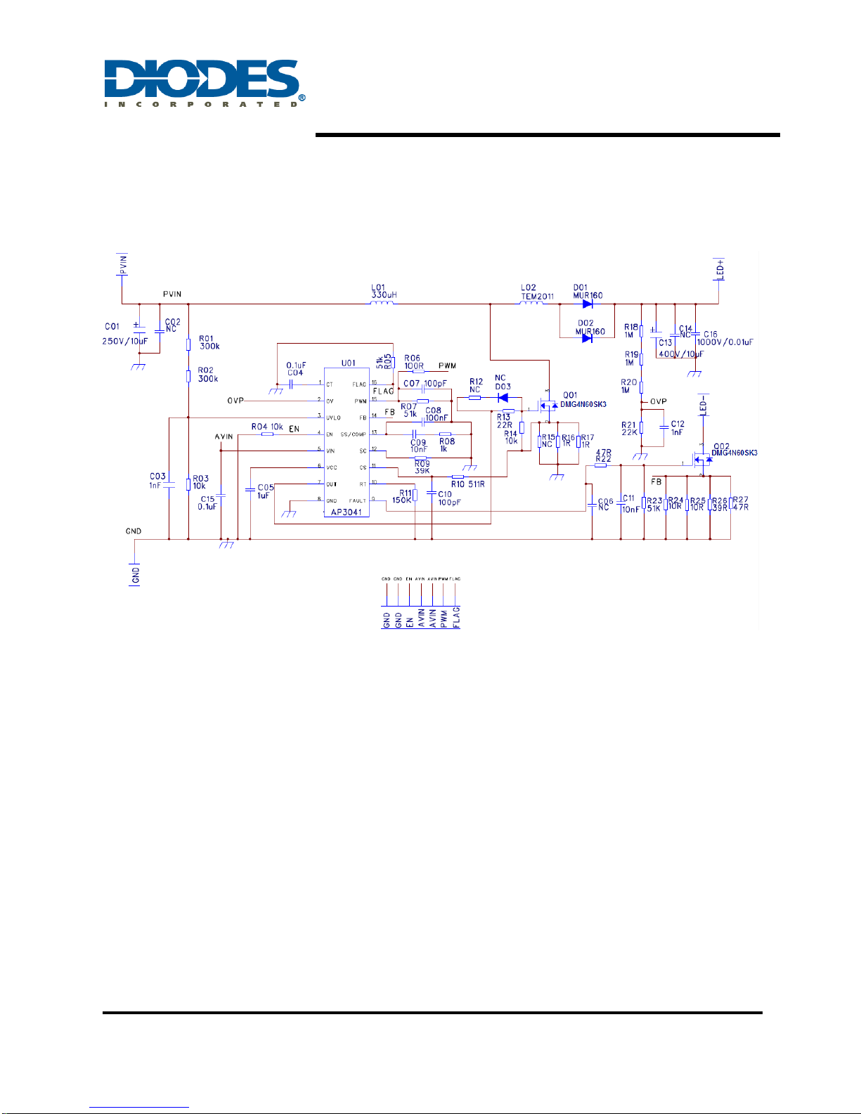
Evaluation Board Schematic
Figure 3: Evaluation Board Schematic
AP3041EV1 Page 3 of 7
May 2014
www.diodes.com
Page 4
AP3041EV1 User Guide
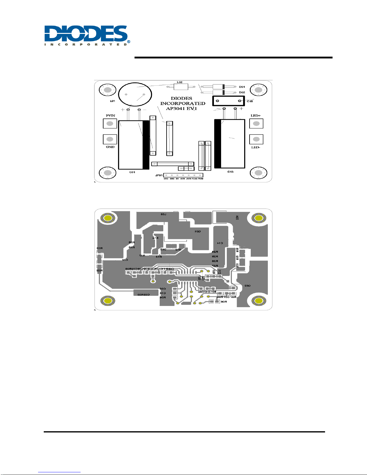
Evaluation Board Layout
Figure 4: PCB Board Layout Top View
Quick Start Guide
1. By default, the evaluation board is preset at 125mA LED Current.
2. Connect the anode wire of external LED string to LED+ pin.
3. Connect the cathode wire of external LED string to LED- pin.
4. System Power Supply: Apply 100VDC to PVIN & GND pin.
5. Enable the IC: Apply 12VDC to AVIN & GND pin, and apply 5VDC to EN & GND pin to enable
AP3041.
6. Dimming Signal: Apply a synchronal PWM signal (Vpp=5V) to PVIN & GND pin to dim the
LEDs. When the dimming function is not applied, please apply 5 VDC to PVIN & GND pin.
7. LED string should light up after 4~6 steps.
AP3041EV1 Page 4 of 7
May 2014
www.diodes.com
Figure 5: PCB Board Layout Bottom View
Page 5
AP3041EV1 User Guide
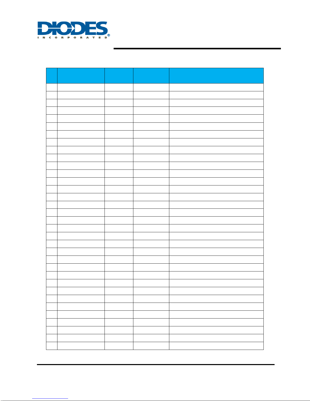
#
Name
Quantity
Package
Description
1
U01
1
SO-16
AP3041
2
C01
1
RAD-0.2
250V/10uF
3
C13
1
RAD-0.2
400V/10uF
4
C03 C12
2
0805
1nF
5
C04 C15 C08
3
0805
0.1uF
6
C16
1
RAD-0.2
1000V/0.01uF
7
C07
1
1206
100pF
8
C10
1
0805
100pF
9
C09 C11
2
0805
10nF
10
C05
1
0805
1uF
11
C06
1
0805
NC
12
D01 D02
2
DO-41
MUR160
13
D03
1
LL-34
NC
14
L01 1 RAD-0.2
330uH
15
L02 1 CASE 59-04
WIRE JUMPER
16
Q01 Q02
2
DPAK
DMG4N60SK3
17
R06
1
0805
100
18
R24 R25
2
1206
10
19
R03 R04 R14
3
0805
10k
20
R11
1
0805
150K
21
R18 R19 R20
3
0805
1M
22
R16 R17
2
1206
1
23
R08
1
0805
1k
24
R21
1
0805
22K
25
R13
1
1206
22
26
R01 R02
2
0805
300k
27
R09
1
0805
39K
28
R26
1
1206
39R
29
R22
1
0805
47R
30
R27
1
1206
47R
31
R10
1
0805
511
32
R23
1
0805
51K
33
R05 R07
2
1206
51k
34
C02 C14 R12 R15
4
1206
NC
Bill of Material
AP3041EV1 Page 5 of 7
May 2014
www.diodes.com
Page 6
AP3041EV1 User Guide
0
20
40
60
80
100
120
140
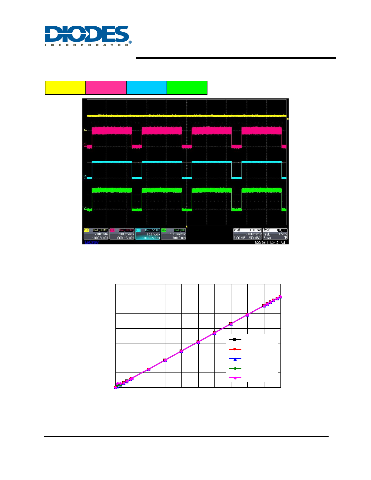
0 10 20 30 40 50 60 70 80 90 100
PWM Duty(%)
LED Current(mA)
PWM=70Hz
PWM=200Hz
PWM=500Hz
PWM=1kHz
PWM=2kHz
V
SS/COMP
V
FB
V
FAULT
I
LED
Functional Waveforms
PWM Dimming Waveform (Dimming=200Hz; Duty=80%; ILED=120mA)
Functional Data Curves
AP3041EV1 Page 6 of 7
May 2014
www.diodes.com
PWM Dimming (Output Current vs. Duty Cycle)
Page 7

AP3041EV1 User Guide
IMPORTANT NOTICE
DIODES INCORPORATED MAKES NO WARRANTY OF ANY KIND, EXPRESS OR IMPLIED, WITH REGARDS TO THIS
DOCUMENT, INCLUDING, BUT NOT LIMITED TO, THE IMPLIED WARRANTIES OF MERCHANTABILITY AND FITNESS FOR A
PARTICULAR PURPOSE (AND THEIR EQUIVALENTS UNDER THE LAWS OF ANY JURISDICTION).
Diodes Incorporated and its subsidiaries reserve the right to make modifications, enhancements, improvements, corrections or other
changes without further notice to this document and any product described herein. Diodes Incorporated does not assume any
liability arising out of the application or use of this document or any product described herein; neither does Diodes Incorporated
convey any license under its patent or trademark rights, nor the rights of others. Any Customer or user of this document or products
described herein in such applications shall assume all risks of such use and will agree to hold Diodes Incorporated and all the
companies whose products are represented on Diodes Incorporated website, harmless against all damages.
Diodes Incorporated does not warrant or accept any liability whatsoever in respect of any products purchased through unauthorized
sales channel.
Should Customers purchase or use Diodes Incorporated products for any unintended or unauthorized application, Customers shall
indemnify and hold Diodes Incorporated and its representatives harmless against all claims, damages, expenses, and attorney fees
arising out of, directly or indirectly, any claim of personal injury or death associated with such unintended or unauthorized
application.
Products described herein may be covered by one or more United States, international or foreign patents pending. Product names
and markings noted herein may also be covered by one or more United States, international or foreign trademarks.
LIFE SUPPORT
Diodes Incorporated products are specifically not authorized for use as critical components in life support devices or systems
without the express written approval of the Chief Executive Officer of Diodes Incorporated. As used herein:
A. Life support devices or systems are devices or systems which:
1. are intended to implant into the body, or
2. support or sustain life and whose failure to perform when properly used in accordance with instructions for use provided
in the labeling can be reasonably expected to result in significant injury to the user.
B. A critical component is any component in a life support device or system whose failure to perform can be reasonably expected
to cause the failure of the life support device or to affect its safety or effectiveness.
Customers represent that they have all necessary expertise in the safety and regulatory ramifications of their life support devices or
systems, and acknowledge and agree that they are solely responsible for all legal, regulatory and safety-related requirements
concerning their products and any use of Diodes Incorporated products in such safety-critical, life support devices or systems,
notwithstanding any devices- or systems-related information or support that may be provided by Diodes Incorporated. Further,
Customers must fully indemnify Diodes Incorporated and its representatives against any damages arising out of the use of Diodes
Incorporated products in such safety-critical, life support devices or systems.
Copyright © 2013, Diodes Incorporated
www.diodes.com
AP3041EV1 Page 7 of 7
May 2014
www.diodes.com
 Loading...