

Page 1
AP1121
DUAL 1A LOW DROPOUT POSITIVE REGULATOR
Features
• 1.3V maximum dropout at full load current
• Fast transient response
• Output current limiting for each channel
• Built-in thermal shutdown for each channel
• Good noise rejection
• Dual output ch1 = 3.3V, ch2 = 2.5V
(ch2 = 1.8V for version B)
• SOP-8L: Available in “Green” Molding Compound
(No Br, Sb)
Lead Free Finish/ RoHS Compliant (Note 1)
Applications
• PC peripheral
• Communication
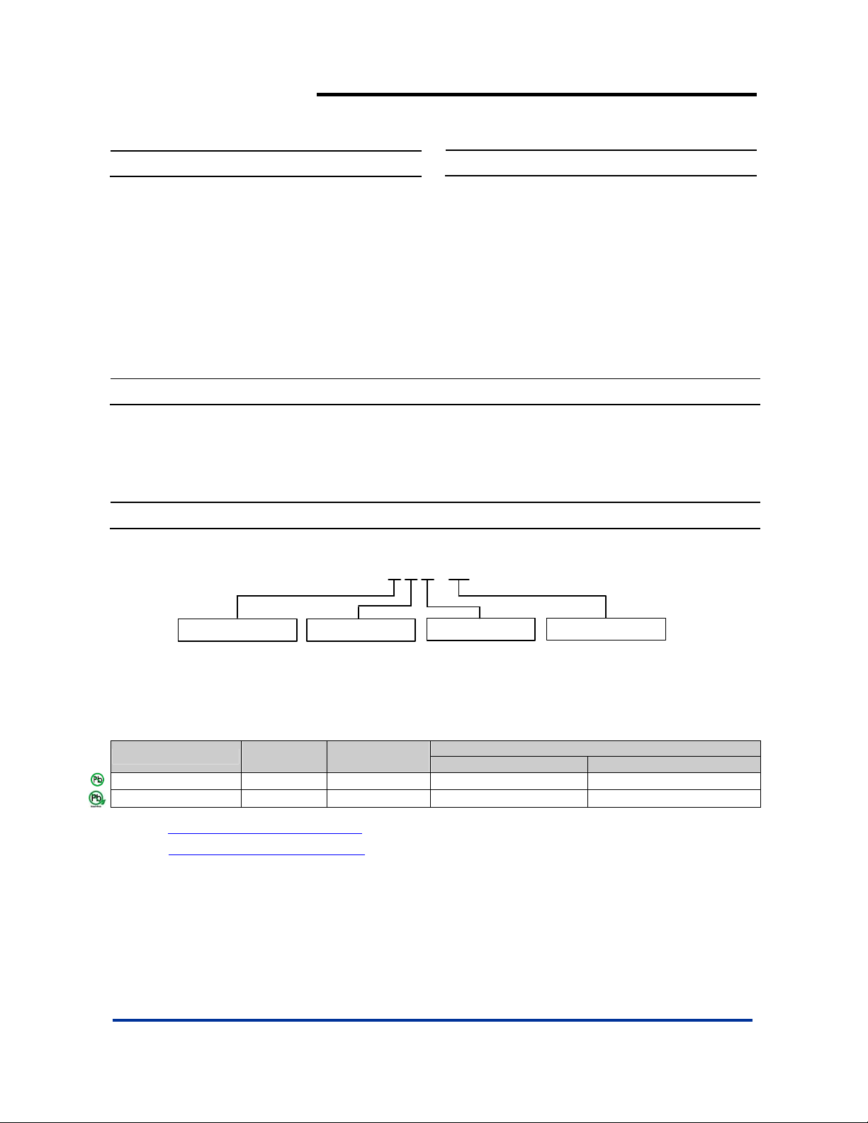
Ordering Information
AP 1121 X S X - 13
General Description
AP1121 is a low dropout positive regulator which provides 1A
output current capability. The product is specifically designed to
provide well-regulated supply for low voltage IC applications such
as high-speed bus termination and low current 3.3V/2.5V or
3.3V/1.8V logic supply. AP1121 is guaranteed to have <1.3V
dropout at full load current making it ideal to provide well
regulated outputs dual channels with up to 18V input supply.
Vout
A : CH1=3.3V
CH2=2.5V
Package
S : SOP-8L
Lead Free
L : Lead Free
G : Green
Packing
13 : Tape & Reel
B : CH1=3.3V
CH2=1.8V
Device
AP1121XSL-13
Lead-free
AP1121XSG-13
Notes: 1. EU Directive 2002/95/EC (RoHS). All applicable RoHS exemptions applied. Please visit our website at
http://www.diodes.com/products/lead_free.html
2. Pad layout as shown on Diodes Inc. suggested pad layout document AP02001, which can be on found our website at
http://www.diodes.com/datasheets/ap02001.pdf
Package
Code
S SOP-8L 2500/Tape & Reel -13
S SOP-8L 2500/Tape & Reel -13
Packaging
(Note 2)
.
.
Quantity Part Number Suffix
13” Tape and Reel
AP1121 Rev. 5 1 of 7 FEBRUARY 2009
www.diodes.com © Diodes Incorporated
Page 2
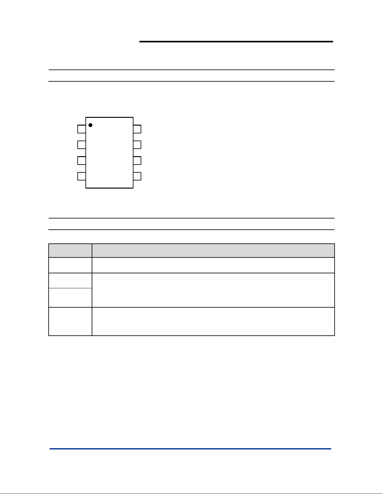
Pin Assignments
( Top View )
AP1121
DUAL 1A LOW DROPOUT POSITIVE REGULATOR
V
OUT1
V
IN1
1
2
GND
8
GND
7
AP1121
3
V
IN2
OUT2
4
V
SOP-8L
6
GND
5
GND
Pin Descriptions
Pin Name Descriptions
GND Ground
3.3V(V
2.5V/1.8V
(V
OUT2
OUT1
)
)
The output of the regulator. A minimum of 10uF c apacitor (0.15 Ω ≤ ESR ≤ 20Ω) must be
connected from this pin to ground to insure stability.
VIN
AP1121 Rev. 5 2 of 7 FEBRUARY 2009
The input pin of regulator. Typically a large storage capacitor (0.15Ω ≤ ESR ≤ 20Ω) is
connected from this pin to ground.
www.diodes.com © Diodes Incorporated
Page 3
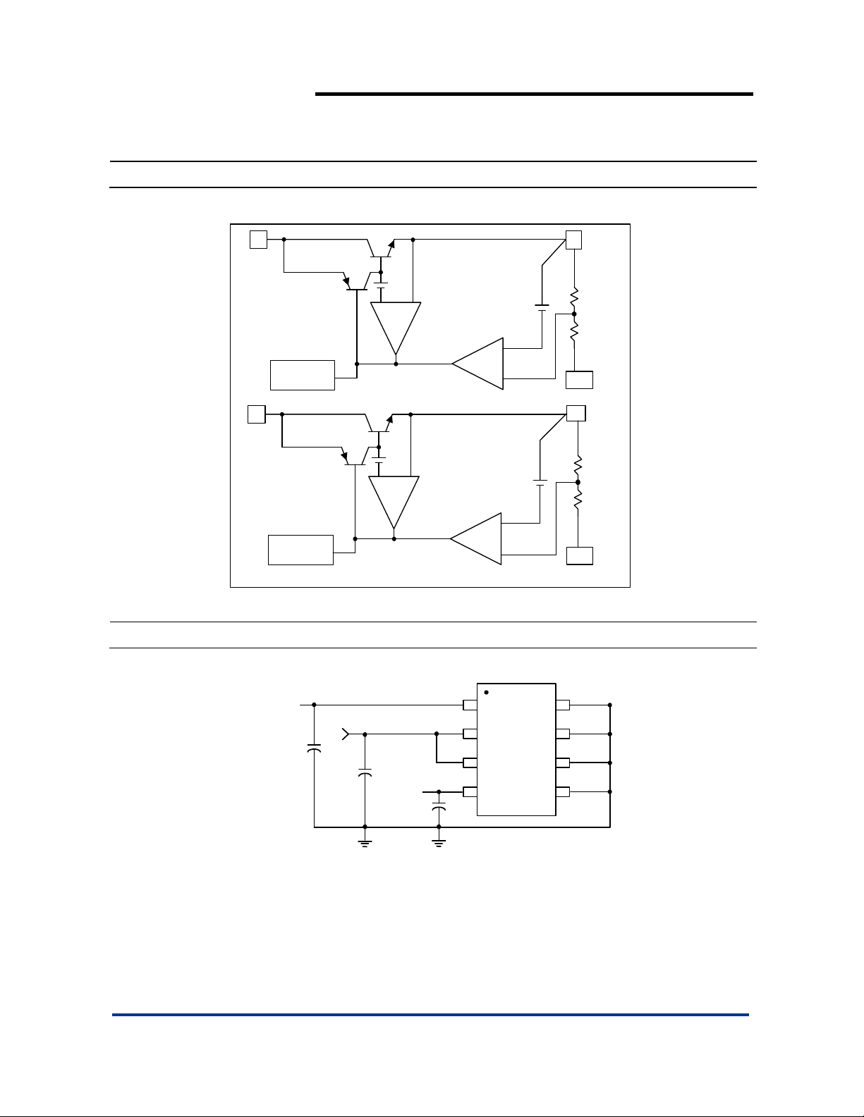
Block Diagram
AP1121
DUAL 1A LOW DROPOUT POSITIVE REGULATOR
2
V
IN1
Thermal
Shutdown
3
V
IN2
Thermal
Shutdown
Typical Application Circuit
1
V
OUT1
+
-
+
CURRENT
LIMIT
+
-
+
CURRENT
LIMIT
+
+
-
1.25V
-
1.25V
+
5/6
GND
4
V
OUT2
+
7/8
GND
3.3V/1A
C1
100uF
5V
C2
100uF
2.5V/1A
C3
V
V
V
OUT1
IN1
IN2
OUT2
GND
GND
GNDV
GND
100uF
(3.3V/2.5V Dual output )
AP1121 Rev. 5 3 of 7 FEBRUARY 2009
www.diodes.com © Diodes Incorporated
Page 4
≤
≤
θ
AP1121
DUAL 1A LOW DROPOUT POSITIVE REGULATOR
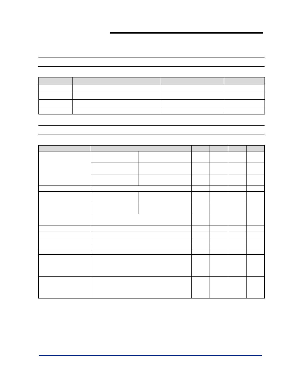
Absolute Maximum Ratings
Symbol Parameter Rating Unit
VIN DC Supply Voltage -0.3 to 18 V V
TST Storage Temperature -65 to +150
TOP Operating Junction Temperature Range 0 to +125
TM Maximum Junction Temperature 150
o
C
o
C
oC
Electrical Characteristics (Under Operating Conditions)
Parameter Conditions Min Typ. Max Unit
= 10mA, TA = 25oC,
I
AP1121_ - V
Output Voltage
AP1121A - V
AP1121B - V
Line Regulation IO = 10mA, V
OUT1
OUT2
OUT2
+1.5V<VIN<12V, TA= 25oC 0.2 %
OUT
AP1121 series
V
Load Regulation
Dropout Voltage
IN-VOUT
)
(V
Current Limit (VIN-V
Minimum Load Current
OUT1
AP1121 series
V
OUT2
I
= 1A, ΔV
OUT
) = 5V 1. 1 A
OUT
o
0
C≤Tj≤125oC (Note 5)
OUT
= 0.1%V
Thermal Regulation TA = 25 oC, 30ms pulse 0.008 0.04 %/W
Ripple Rejection F = 120Hz, C
OUT
Temperature Stability IO = 10mA 0.5 %
Thermal Resistance
JA
Junction-t o - A m bi ent (No
heat sink; No air flow)
SOP-8L: Control Circuitry/Power Transistor
(Note 6)
CH1 or CH2 only
CH1 & CH2 and PD1 = PD2
SOP-8L: Control Circuitry/Power Transistor
θ
Thermal Resistance
JC
Junction-to-Case
(Note 6)
CH1 or CH2 only
CH1 & CH2 and PD1 = PD2
Notes: 3. See thermal regulation specifications for changes in output voltage due to heating effects. Line and load regulation are measured at a constant
junction temperature by low duty cycle pulse testing. Load regulation is measured at the output lead = 1/18” from the package.
4. Line and load regulation are guaranteed up to the maximum power dissipation of 15W. Power dissipation is determined by the input/output
5. Quiescent current is defined as the minimum output current that requires maintaining regulation. At 12V input/output diffe rential the device is
differentially and the output current. Guaranteed maximum power dissipation will not be available over the full input/output range.
guaranteed to regulate if the output current is greater than 10mA.
6. Vout1 and Vout2 are connected to the PCB copper area 5.5mm*5.5mm separately. If you need large PD or lower Tc & Tj, please connect to
the large copper area >> 5.5mm*5.5mm (like 10mm*10mm).
AP1121 Rev. 5 4 of 7 FEBRUARY 2009
OUT
4.8V≤V
I
OUT
4V
I
OUT
4V≤V
V
IN
T
A
V
IN
T
A
≤12V
IN
= 10mA, TA = 25oC,
V
12V
IN
= 10mA, TA = 25oC,
≤12V
IN
= 5V, 0≤I
OUT
≤1A,
= 25oC (Note 3, 4)
= 4V, 0mA<Io<1A,
= 25oC (Note 4, 5)
OUT
3.235 3.300 3.365 V
2.450 2.500 2.550 V
1.764 1.800 1.836 V
26 33 mV
20 25 mV
1.3 1.4 V
5 10 mA
= 25uF Tantalu m , I
= 1A 60 70 dB
OUT
177
O
C/W
158
29
O
C/W
19
www.diodes.com © Diodes Incorporated
Page 5
DUAL 1A LOW DROPOUT POSITIVE REGULATOR
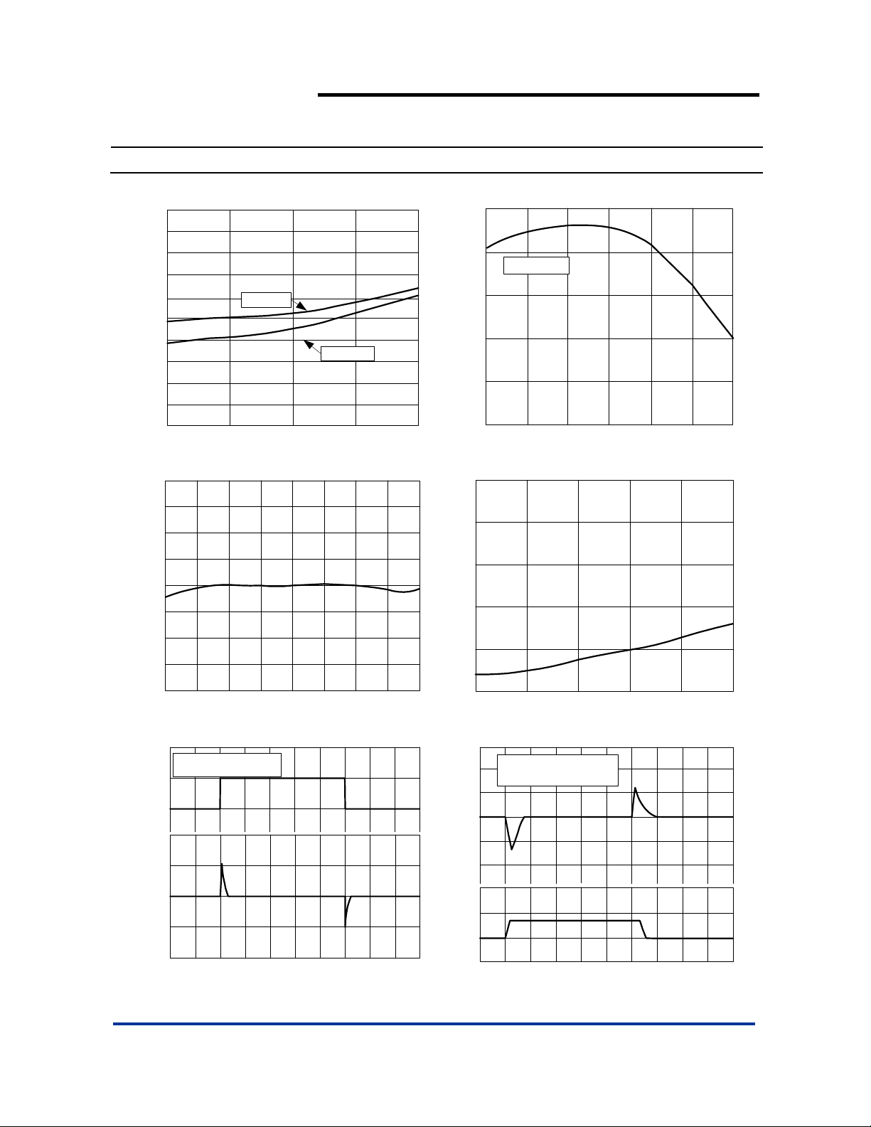
Typical Performance Characteristics
2. 0
1. 8
1. 6
1. 4
1. 2
1. 0
0. 8
0. 6
Dropout Voltage (V)
0. 4
0. 2
0
0
Dropout Voltage vs Output Current
Tj = 25 oC
250
500
Output Current (mA)
Tj = 125 oC
750
1000
0.20
0
I load=800mA
-0.20
-0.40
-0.80
Output Voltage Deviation (%)
- 1
-25 0
25 50 75 100 125
Temperature (oC)
Load Regulation vs Temperature
AP1121
2
1.5
1
0. 5
0
-0.5
- 1
-1.5
Output Voltage Change (%)
- 2
-50 -25 0 25 50 75 100 125 150
Percent Change in Output Voltage vs Temperature
7.5
Cin=1uF
Cout=10uF Tantalum
6.5
5.5
40
20
0
-20
-40
0 20 40 60 80 100 120 140 160 180 200
Output Voltage Deviation (mV) Input Voltage (V)
Temperature (oC)
TIME (us )
Line Transient Response
1
0.8
0.6
0.4
0.2
Output Voltage Deviation (%)
0
24
30
C in = 1uF
20
C out = 10 uF Tantalum
Preload = 100mA
10
0
-10
-20
Output Voltage Deviation (mV)
2
1
0
-1
Load Current (A)
010
20 30 40 50 60 70 80 90 100
Load Transient Response
681012
Input Voltage (V)
Line Regulation
TIME (us)
AP1121 Rev. 5 5 of 7 FEBRUARY 2009
www.diodes.com © Diodes Incorporated
Page 6
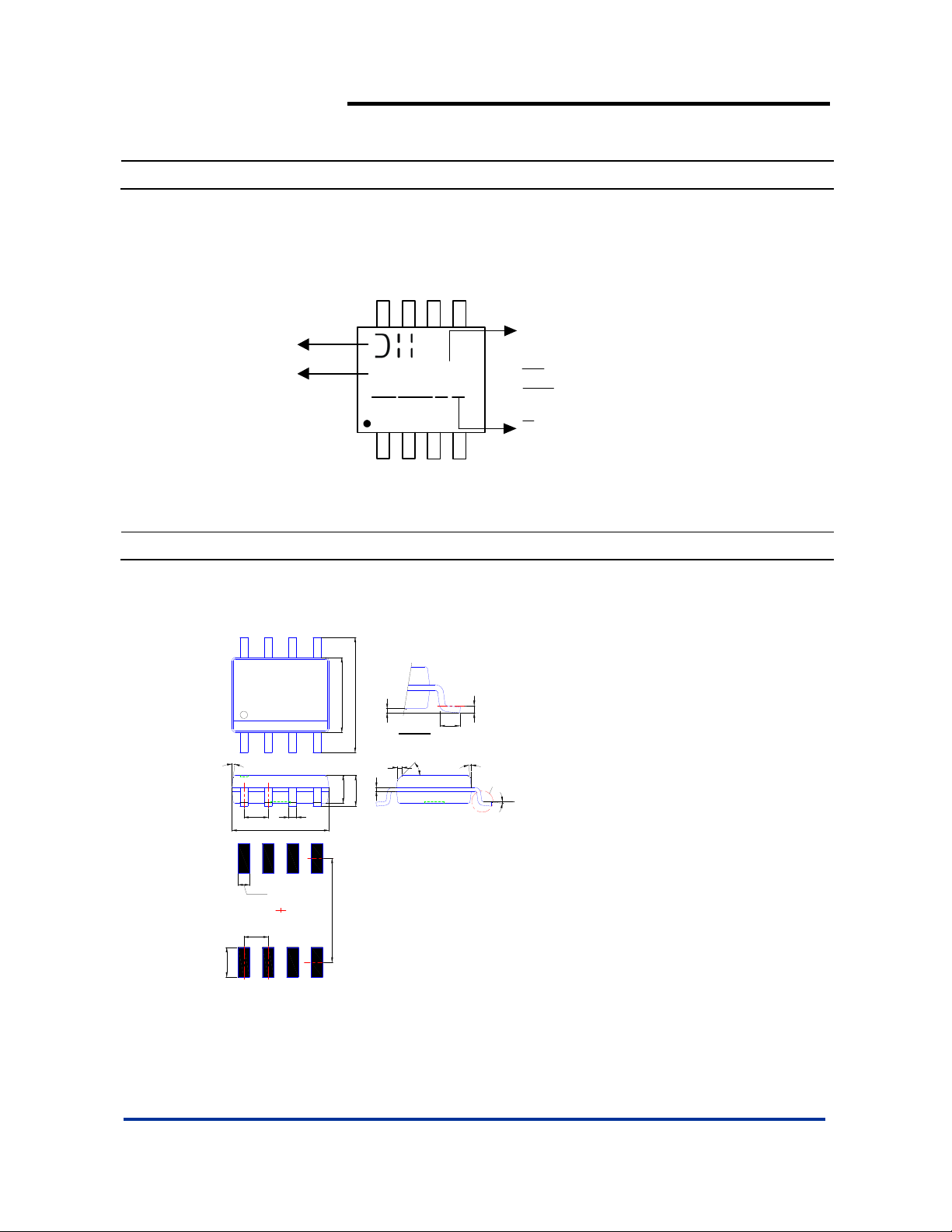
Marking Information
(1) SOP-8L
AP1121
DUAL 1A LOW DROPOUT POSITIVE REGULATOR
( Top View )
Logo
Part Number
Package Information
(1) Package type: SOP-8L
7°~9°
1.27typ
0.3/0.5
4.85/4.95
8
AP1121 X
YY
3.85/3.95
5.90/6.10
0.15/0.25
1.30/1.50
1.75max.
WW X
0.10/0.20
Detail "A"
0.35max.
5
A : 3.3V/2.5V version
B : 3.3V/1.8V version
: Year : 08, 09,10~
YY
X
WW : Week : 01~52; 52
represents 52 and 53 week
: Internal Code
X
L : Lead Free
41
0.254
0.62/0.82
7°~9°
45°
Gauge Plane
Seating Plane
Detail "A"
0°/8°
G : Green
8x-0.60
5.4
6x-1.27
8x-1.55
Land Pattern Recommendation
(Unit: mm)
AP1121 Rev. 5 6 of 7 FEBRUARY 2009
www.diodes.com © Diodes Incorporated
Page 7

AP1121
DUAL 1A LOW DROPOUT POSITIVE REGULATOR
IMPORTANT NOTICE
Diodes Incorporated and its subsidiaries reserve the right to make modifications, enhancements, improvements, corrections or other changes without further
notice to any product herein. Diodes Incorporated does not assume any liability arising out of the application or use of any product described herein; neither
does it convey any license under its patent rights, nor the rights of others. The user of products in such applications shall assume all risks of such use and will
agree to hold Diodes Incorporated and all the companies whose products are represented on our website, harmless against all damages.
LIFE SUPPORT
Diodes Incorporated products are not authorized for use as critical components in life support devices or systems without the expressed written approval of the
President of Diodes Incorporated.
AP1121 Rev. 5 7 of 7 FEBRUARY 2009
www.diodes.com © Diodes Incorporated
 Loading...