

Page 1
AH293
LOW VOLTAGE HALL-EFFECT SMART FAN MOTOR
CONTROLLER
Description
AH293 is a monolithic fan motor controller with Hall sensor’s
capability. It contains two complementary open-collector
transistors for Motor’s coil driving, automatic lock current
shutdown, and recovery protections. Also, rotor-state
detection (RD) output is for speed detection.
Rotor-lock shutdown detection circuit turns off the output
driver when the rotor is blocked to avoid coil overheat. Then,
the automatic recovery circuit will restart the motor. These
protected actions are repeated and periodic during the
blocked period. Until the blocking is removed, the motor
recovers and runs normally.
The AH293 is available in SOT89-5L package.
Features
• On Chip Hall Sensor
• Rotor-Locked Shutdown
• Automatically Restart
• Rotor-State Detection (RD) Output
• Built-in Zener Protection for Output Driver
• Operating Voltage: 1.8V~5.75 V
• Output Current: I
• Packaged in SOT89-5L
• Green Molding Compound
O(AVE)
= 400 mA
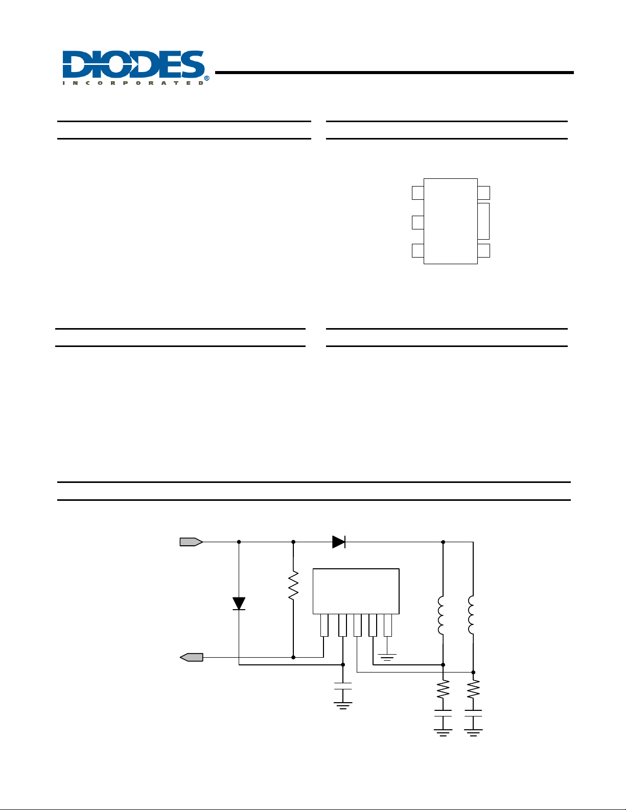
Pin Assignments
(Top View)
Vdd
1
GND
2
3 7
293
SOT89-5L
RD
5
DOBDO
4
Applications
• Two-coil BLDC cooling fans
• Low to medium voltage, low power BLDC motors
Typical Application Circuit (Note 1)
V
dd
(1.8V/5.75V)
D1
RD
(alarm)
Notes: 1. R1, R2: typical 56 Ohm
C1, C2, C3: typical 2.2µF
The R, C value need to be fine tuned based
on coils design.
1.8V/5.75V DC Brush-Less Fan with RD Output Function
AH293
Document number: DS31048 Rev. 6 - 2
R
pu
1 of 8
www.diodes.com
D2
293
Coil2 Coil1
1
32
4
5
GND
C3
R1 R2
C1 C2
June 2010
© Diodes Incorporated
Page 2
Pin Descriptions
Pin Name Description
RD Rotor-State Detection
Vdd Input Power
DO Output Pin
DOB Output Pin
GND Ground
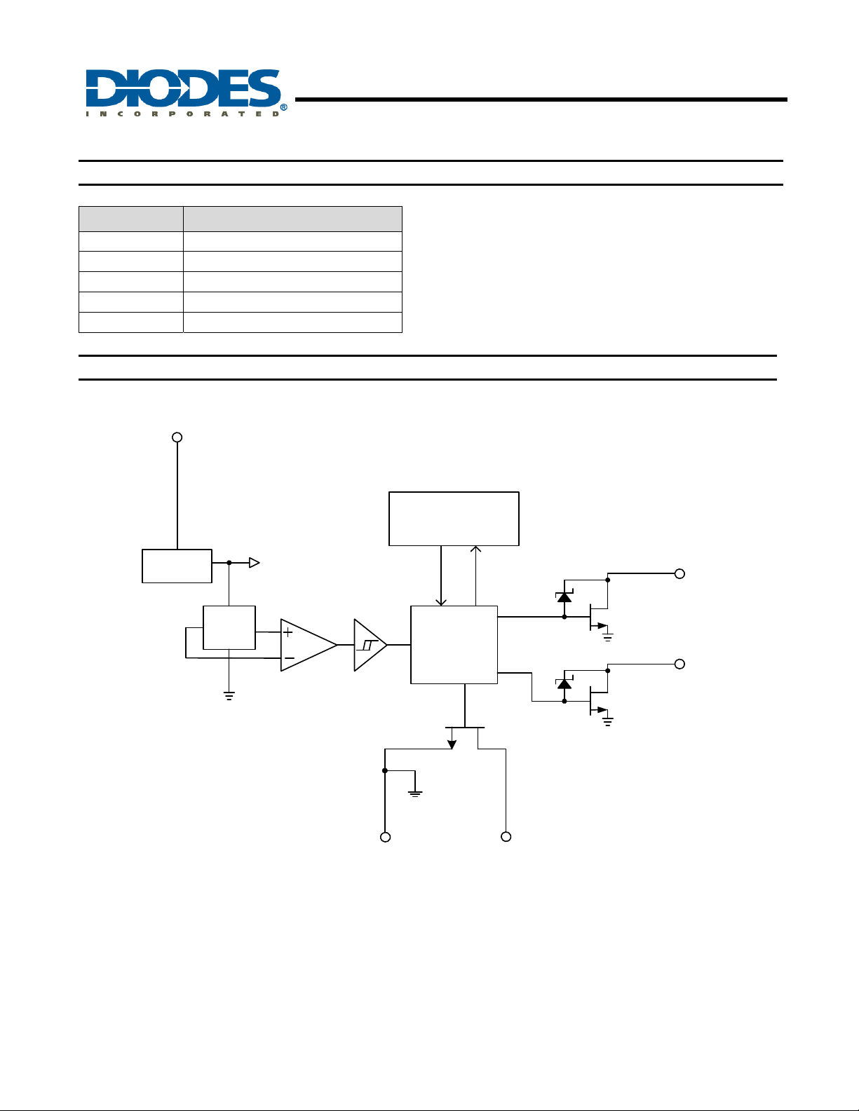
Functional Block Diagram
Vdd
AH293
LOW VOLTAGE HALL-EFFECT SMART FAN MOTOR
CONTROLLER
Regulator
Hall
Plate
AH293
Document number: DS31048 Rev. 6 - 2
Amp.
Lock detect,
shutdown and
automatic re-start
Control Logic
GND
2 of 8
www.diodes.com
RD
DO
DOB
June 2010
© Diodes Incorporated
Page 3
AH293
LOW VOLTAGE HALL-EFFECT SMART FAN MOTOR
CONTROLLER
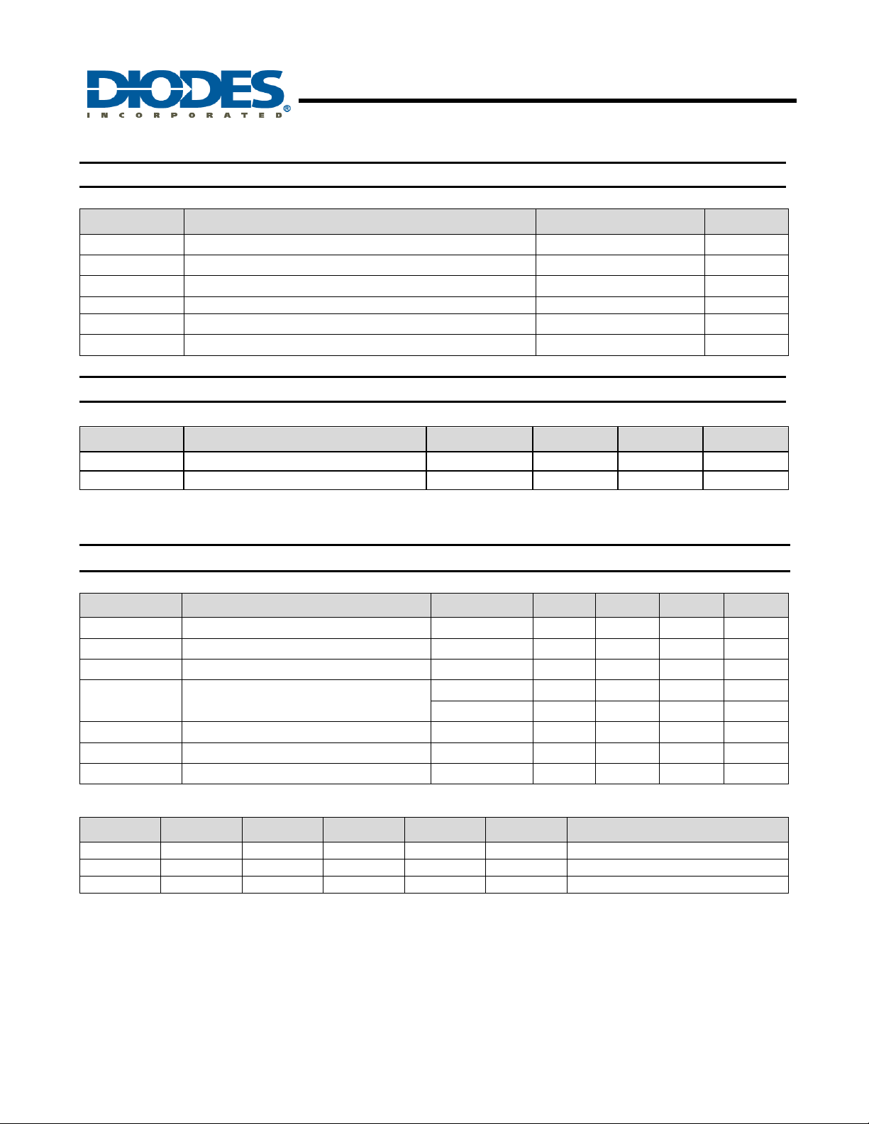
Absolute Maximum Ratings (T
Symbol Characteristics Rating Unit
Vdd Operating Supply Voltage 8 V
I
Output Current 400 mA
O(AVE)
I
Output Current 700 mA
O(PEAK)
PD Power Dissipation 800 mW
TST Storage Temperature -55 ~ 150
TJ Maximum Junction Temperature 150
Recommended Operating Conditions
Symbol Characteristic Conditions Min Max Unit
Vdd Supply Voltage (Note 2) Operating 1.8 5.75 V
TA Operating Ambient Temp erature Operating -20 100
Notes: 2. The output of IC will be switched after the supply voltage is over 1.8V, but the magnetic characteristics won't be normal until the
supply is over 2.0V.
= 25°C)
A
°C
°C
°C
Electrical Characteristics (T
= 25 °C, Vdd = 5V, unless otherwise specified)
A
Symbol Characteristics Conditions Min Typ. Max Unit
Idd Supply current Operating - 2.6 4.0 mA
T
RLP-ON
T
RLP-OFF
V
OUT(SAT)
R
DS(ON)
Rotor Lock Protection On Time - 0.4 - Sec
Rotor Lock Protection Off Time 2.4 3 3.6 Sec
I
= 180mA - 300 - mV
Output Saturation Voltage
O
IO = 350mA - 600 - mV
Output On Resistance - 1.75 - ohm
VOL RD Output Vds IO = 10mA - 0.5 - V
Vz Output Zener-Breakdown Voltage - 15 - V
Truth Table (Note 3)
IN- IN+ CT OUT1 OUT2 RD Mode
H L L H L L Rotating
L H L L H L Rotating
- - H off off off Lockup protection activated
Notes: 3. Latch-type RD output is low during rotor rotation and high when the rotor is locked (not rotating)
AH293
Document number: DS31048 Rev. 6 - 2
3 of 8
www.diodes.com
June 2010
© Diodes Incorporated
Page 4
LOW VOLTAGE HALL-EFFECT SMART FAN MOTOR
CONTROLLER
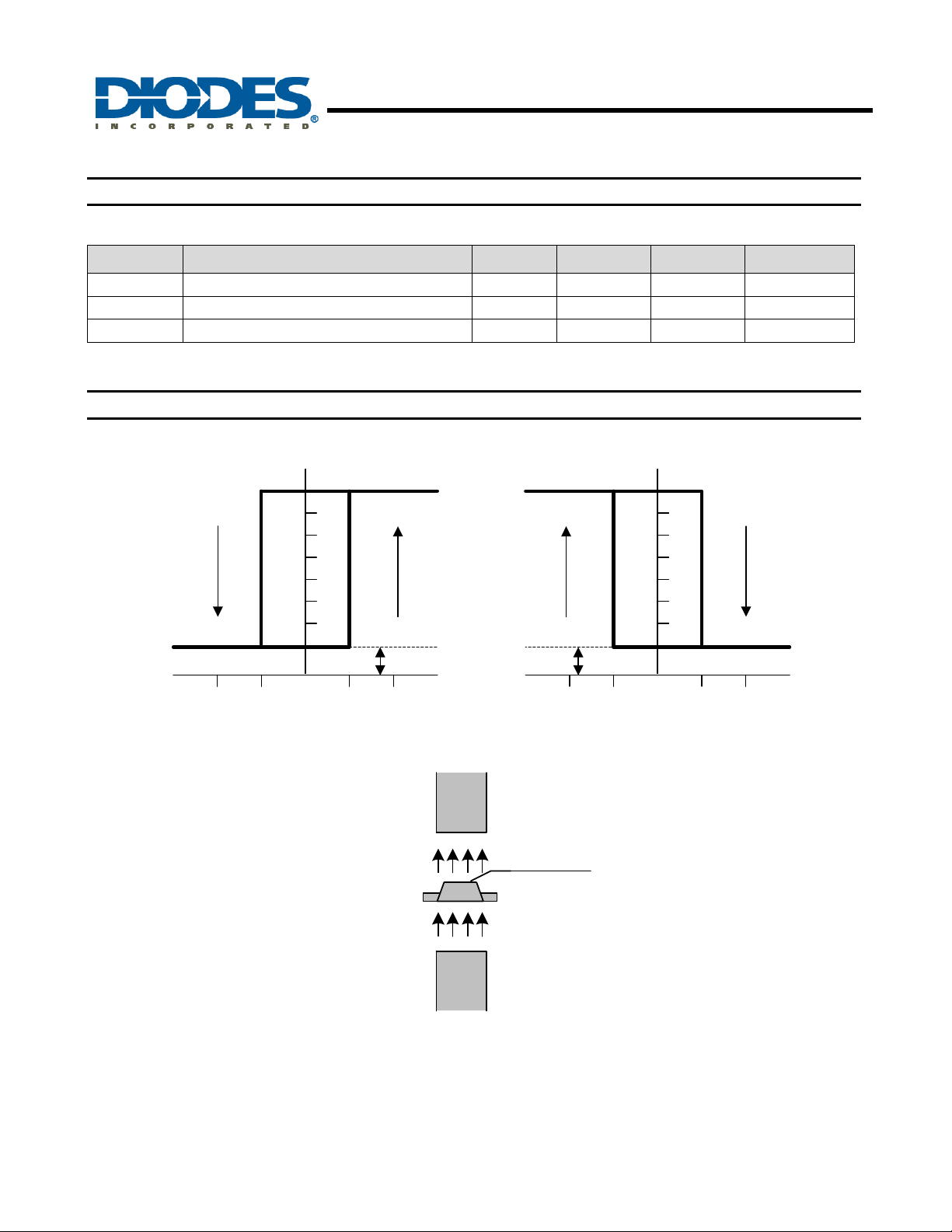
Magnetic Characteristics (T
Symbol Characteristics Min Typ. Max Unit
Bop Operation Point - 30 60 Gauss
Brp Release Point -60 -30 - Gauss
Bhy Hysteresis - 60 - Gauss
Notes: 4. The magnetic characteristics may vary with supply voltage, operating temperature and after soldering.
Operating Characteristics
DOB DO
= 25 °C, Vdd = 5V, unless otherwise specified, Note 4)
A
(1mT = 10 Gauss)
AH293
RP
ON
Output Voltage in Volts
12
10
8
6
4
2
OFF
OP
Vsat Vsat
OFF
RP
Output Voltage in Volts
Magnetic Flux Density in GaussMagnetic Flux Density in Gauss
12
10
8
6
4
2
OP
ON
BopBrp 0BopBrp 0
S
Marking
side
AH293
Document number: DS31048 Rev. 6 - 2
N
( SOT89-5L )
4 of 8
www.diodes.com
June 2010
© Diodes Incorporated
Page 5
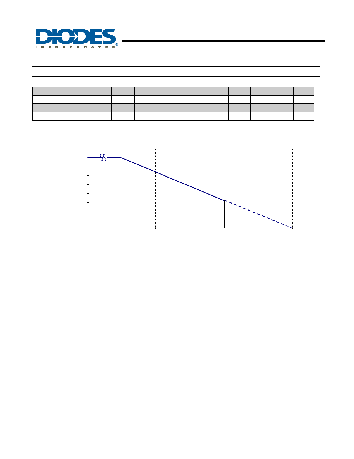
Performance Characteristics
25 50 60 70 75 80 85 90 95 100
800 640 576 512 480 448 416 384 352 320
105 110 115 120 125 130 135 140 145 150
288 256 224 192 160 128 96 64 32 0
-40
0 25 50 75 100 125 150
TA (°C)
PD (mW)
TA (°C)
PD (mW)
P
D
(mW)
900
800
700
600
500
400
300
200
100
0
AH293
LOW VOLTAGE HALL-EFFECT SMART FAN MOTOR
CONTROLLER
Power Dissipation Curve
TA (°C)
AH293
Document number: DS31048 Rev. 6 - 2
5 of 8
www.diodes.com
June 2010
© Diodes Incorporated
Page 6
AH293
LOW VOLTAGE HALL-EFFECT SMART FAN MOTOR
CONTROLLER
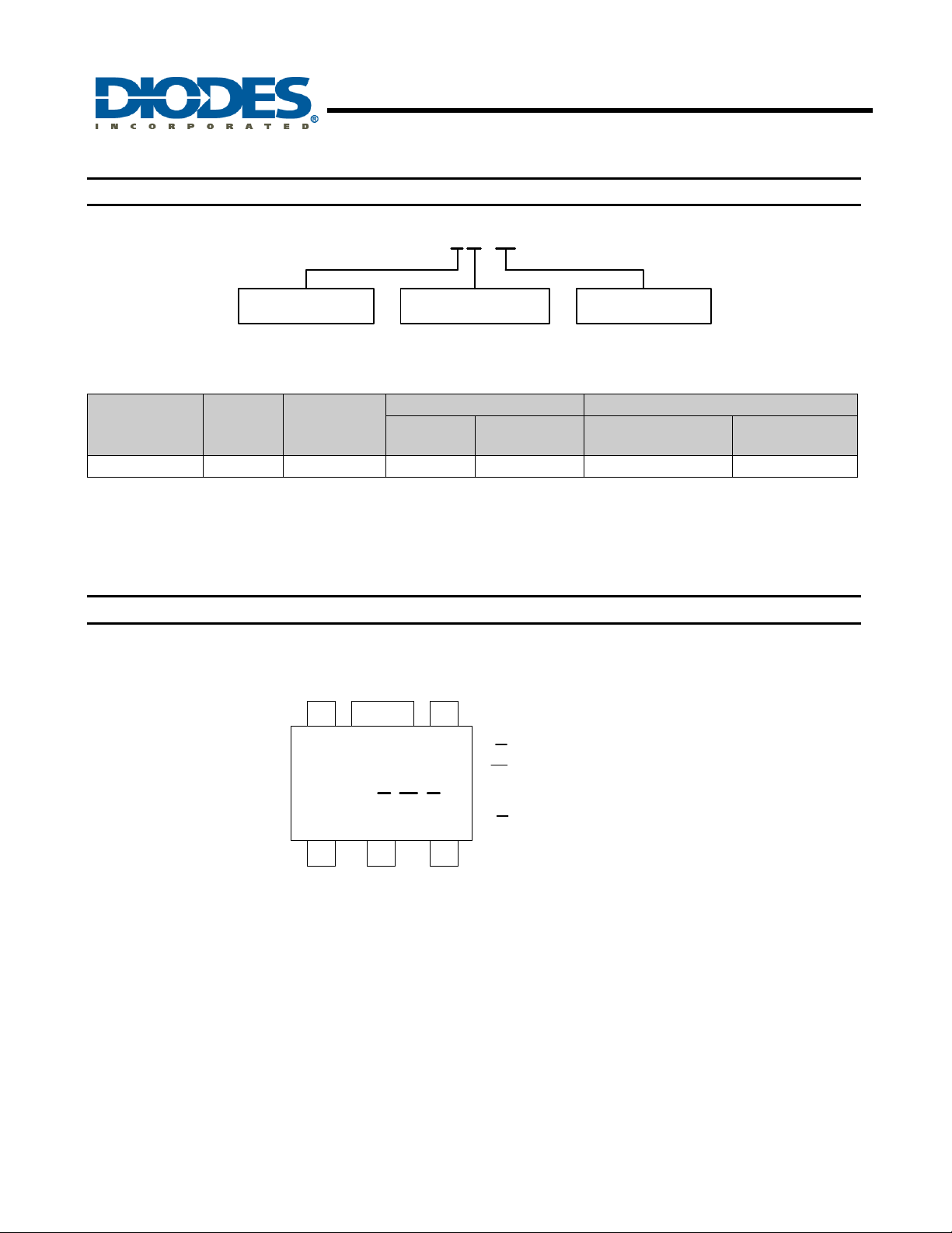
Ordering Information
AH 293 - Y G - 13
PackingPackage Green
Y : SOT89-5L 13 : Tape & ReelG : Green (Note 5)
Device
AH293-YG-13 Y SOT89-5L NA NA 2500/Tape & Reel -13
Notes: 5. EU Directive 2002/95/EC (RoHS). All applicable RoHS exemptions applied. Please visit our website at
http://www.diodes.com/products/lead_free.html.
6. Pad layout as shown on Diodes Inc. suggested pad layout document AP02001, which can be found on our website at
http://www.diodes.com/datasheets/ap02001.pdf.
7. Reverse taping as shown on Diodes Inc. Surface Mount (SMD) Packaging document AP02007, which can be found on our website
http://www.diodes.com/datasheets/ap02007.pdf.
Package
Code
Packaging
(Note 6, 7)
Quantity
Bulk 13” Tape and Reel
Part Number
Suffix
Quantity
Part Number
Suffix
Marking Information
(Top View)
5
293 Y W X
1 2 3
SOT89-5L
4
7
Y : Year : 0~9
: Week : A~Z : 1~26 week;
W
a~z : 27~52 week;
z represents 52 and 53 week
: Internal code
X
A~Z : Green
AH293
Document number: DS31048 Rev. 6 - 2
6 of 8
www.diodes.com
June 2010
© Diodes Incorporated
Page 7
LOW VOLTAGE HALL-EFFECT SMART FAN MOTOR
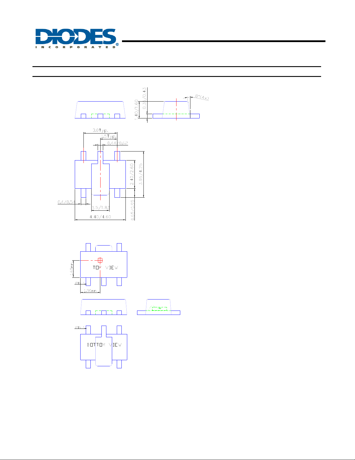
Package Outline Dimensions (All Dimensions in mm)
AH293
CONTROLLER
Sensor Location
AH293
Document number: DS31048 Rev. 6 - 2
7 of 8
www.diodes.com
June 2010
© Diodes Incorporated
Page 8

AH293
LOW VOLTAGE HALL-EFFECT SMART FAN MOTOR
CONTROLLER
IMPORTANT NOTICE
DIODES INCORPORATED MAKES NO WARRANTY OF ANY KIND, EXPRESS OR IMPLIED, WITH REGARDS TO THIS
DOCUMENT, INCLUDING, BUT NOT LIMITED TO, THE IMPLIED WARRANTIES OF MERCHANTABILITY AND FITNESS FOR A
PARTICULAR PURPOSE (AND THEIR EQUIVALENTS UNDER THE LAWS OF ANY JURISDICTION).
Diodes Incorporated and its subsidiaries reserve the right to make modifications, enhancements, improvements, corrections or other
changes without further notice to this document and any product described herein. Diodes Incorporated does not assume any liability
arising out of the application or use of this document or any product described herein; neither does Diodes In corporated convey any
license under its patent or trademark rights, nor the rights of others. Any Customer or user of this documen t or products described
herein in such applications shall assume all risks of such use and will agree to hold Diodes Incorporated and all the companies
whose products are represented on Diodes Incorporated website, harmless against all damages.
Diodes Incorporated does not warrant or accept any liability whatsoever in respect of any products purchased through unauthorized
sales channel.
Should Customers purchase or use Diodes Incorporated products for any unintended or unauthorized application, Customers shall
indemnify and hold Diodes Incorporated and its representatives harmless against all claims, damages, expenses, and attorney fees
arising out of, directly or indirectly, any claim of personal injury or death associated with such unintended or unauthorized application.
Products described herein may be covered by one or more United States, international or foreign p atents pending. Product names
and markings noted herein may also be covered by one or more United States, international or foreign trademarks.
LIFE SUPPORT
Diodes Incorporated products are specifically not authorized for use as critical components in life support devices or systems without
the express written approval of the Chief Executive Officer of Diodes Incorporated. As used herein:
A. Life support devices or systems are devices or systems which:
1. are intended to implant into the body, or
2. support or sustain life and whose failure to perform when properly used in accordance with instructions for use provided
in the labeling can be reasonably expected to result in significant injury to the user.
B. A critical component is any component in a life support device or system whose failure to perform can be reasonably expected
to cause the failure of the life support device or to affect its safety or effectiveness.
Customers represent that they have all necessary expertise in the safety and regulatory ramifications of their life support dev ices or
systems, and acknowledge and agree that they are solely responsible for all legal, regulatory and safety-related requirements
concerning their products and any use of Diodes Incorporated products in such safety-critical, life support devices or systems,
notwithstanding any devices- or systems-related information or support that may be provided by Diodes Incorporated. Further,
Customers must fully indemnify Diodes Incorporated and its representatives against any damages arising out of the use of Diodes
Incorporated products in such safety-critical, life support devices or systems.
Copyright © 2010, Diodes Incorporated
www.diodes.com
AH293
Document number: DS31048 Rev. 6 - 2
8 of 8
www.diodes.com
June 2010
© Diodes Incorporated
 Loading...