

Page 1
Description
AH1891
MINIATURE MICROPOWER OMNIPOLAR
HALL EFFECT SWITCH
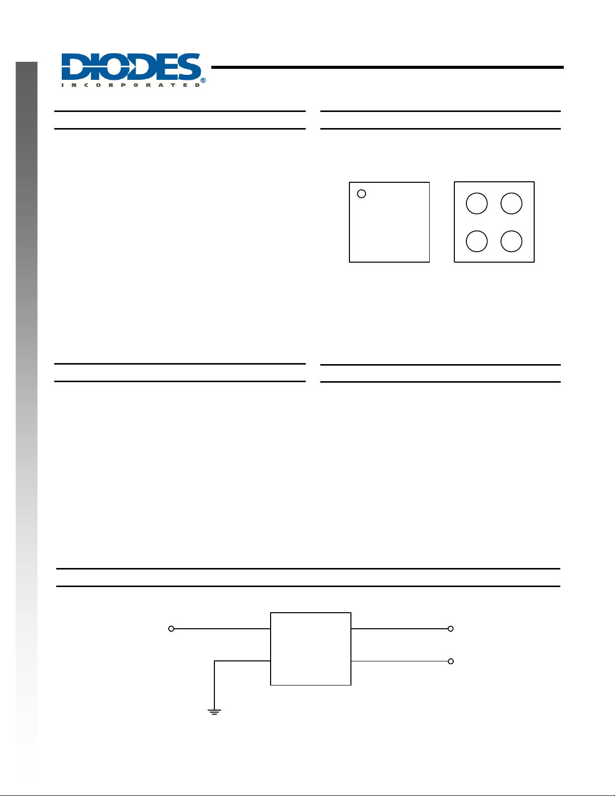
Pin Assignments
The AH1891 is a miniature micropower Omnipolar Hall effect
switch IC with dual outputs specifically designed for portable
and battery powered equipment such as cellular phones and
portable PCs. To support battery powered equipment the
AH1891 has been optimized to operate over the suppl y range
of 1.8V to 3.3V and uses a sleep function to give an aver age
supply current of only 7uA. To minimize PCB space the
AH1891 is packaged in the small CSP package
(0.8mmx0.8mm) and the design integrates the external pull
up resistors to simplify the applications circuit.
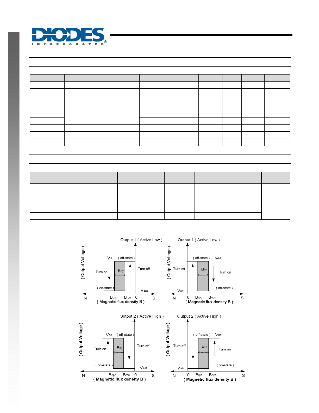
The outputs of the AH1891 are switched with either a North or
South pole of sufficient strength. When the magnetic flux
density (B) is larger than operate point (Bop), Output 1 will
pull low and Output 2 will be inverted (high). The output states
are held until B is lower than release point (Brp).
NEW PRODUCT
The AH1891 is available in U-WLB0808-4 package.
Features
• Omnipolar (North or South) operation
• Low supply voltage of 1.8V to 3.3V
• Micropower operation
• Dual outputs for design flexibility
• Internal pull up and pull down capability
• Chopper stabilized design for:
o Superior temperature stability
o Superior temperature stability
o Superior temperature stability
• Good RF noise immunity
• -40°C to 85°C Operating Temperature
• ESD > 4KV in Human Body Mode
• Miniature CSP package 0.8mm x 0.8mm
Typical Application Circuit
(Top View)
A1 A2
B1 B2
(Bottom View)
A2 A1
B2 B1
Applications
• Cellular phones
• Portable PCs and PDAs
• Digital cameras
• Portable and battery powered applications
AH1891
Document number: DS35207 Rev. 1 - 2
Vdd
GND
AH1891
1 of 7
www.diodes.com
Output 1
Output 2
April 2011
© Diodes Incorporated
Page 2
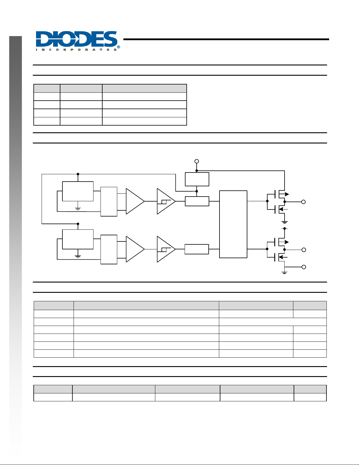
Pin Descriptions
Pin # Pin Name Description
A1 Out 1 Output Pin (active low)
A2 Out 2 Output Pin (active high)
B1 GND Ground
B2 Vdd Power Supply Voltage
Functional Block Diagram
NEW PRODUCT
Hall
Plate
AH1891
MINIATURE MICROPOWER OMNIPOLAR
HALL EFFECT SWITCH
Vdd
Power
Cancelling
Offset
Amp
switch
Latch
Out1
Hall
Plate
Cancelling
Output
Controller
Offset
Amp
Latch
GND
Vdd
Absolute Maximum Ratings (T
Symbol Parameter Values Unit
Vdd Supply voltage 5 V
B Magnetic flux density Unlimited
TA Operating Temperature Range -40 to +85 °C
Ts Storage Temperature Range -65 to +150 °C
PD Package Power Dissipation 166 mW
TJ Maximum Junction Temperature 150 °C
Recommended Operating Conditions (T
Symbol Parameter Conditions Rating Unit
Vdd Supply Voltage Operating 1.8 to 3.3 V
= 25°C)
A
= 25°C)
A
Out2
GND
AH1891
Document number: DS35207 Rev. 1 - 2
2 of 7
www.diodes.com
April 2011
© Diodes Incorporated
Page 3
AH1891
r
Electrical Characteristics (T
Symbol Parameter Conditions Min Typ. Max Unit
VOH Output On Voltage (High side) IO= -0.5mA Vdd-0.2 - - V
VOL Output On Voltage (Low side) IO= 0.5mA - - 0.2 V
Ioff Output Leakage Current Output off -
Idd(en)
Idd(dis) Chip disable - 5 8 uA
Idd(avg) Average supply current - 7 12 uA
Tawake Awake Time - 50 100 µs
Tperiod Period - 50 100 ms
D.C. Duty Cycle - 0.1 - %
Supply Current
Magnetic Characteristics (T
NEW PRODUCT
Symbol
Bops(south pole to brand side)
Bopn(north pole to brand side) -60 -40 -20
Brps(south pole to brand side)
Brpn(north pole to brand side) -50 -25 -12
Bhy(|Bopx|-|Brpx|) Hysteresis 15
Notes: 1. Typical data is at TA = 25°C, Vdd = 3V, and for design information only.
2. Operate point and release point will vary with supply voltage and operating temperature.
= 25°C, Vdd = 1.8V, unless otherwise specified)
A
Chip enable - 2 4 mA
= 25°C, Vdd = 1.8V~3.3V, Note 1)
A
Paramete
(Note 2)
Operate Point
Release Point
MINIATURE MICROPOWER OMNIPOLAR
HALL EFFECT SWITCH
<0.1
Min Typ. Max Unit
20 40 60
12 25 50
1 µA
(1mT=10 Gauss)
Gauss
AH1891
Document number: DS35207 Rev. 1 - 2
3 of 7
www.diodes.com
April 2011
© Diodes Incorporated
Page 4

Typical Operating Characteristics
Switchpointsvs.Temperature
Vdd=1.8V
Temperature (oC)
NEW PRODUCT
60
40
20
0
Gauss(G)
‐20
‐40
‐60
‐55 ‐40 ‐25 ‐105 203550658095
MINIATURE MICROPOWER OMNIPOLAR
Switch Points Bop and Brp vs. Temperature
Switchpointsvs.Temperature
Vdd=3.3V
60
T
=25oC
A
40
20
0
Gauss(G)
‐20
‐40
‐60
‐55 ‐40 ‐25 ‐10 5 203550658095
Tempe rature(oC)
Bops
Brps
Bopn
Brpn
Bhy_S
Bhy_N
Switch Points Bop and Brp vs. Supply Voltage
Switchpointsvs.Supplyvoltage
60
AH1891
HALL EFFECT SWITCH
Bops
Brps
Bopn
Brpn
Bhy_S
Bhy_N
40
20
0
Gauss(G)
‐20
‐40
‐60
1.5 1.8 2.1 2.4 2.7 3 3.3
SupplyvoltageVdd(V)
Bops
Brps
Bopn
Brpn
Bhys_S
Bhys_N
Average Supply Current vs. Temperature Average Supply Current vs. Supply Voltage
Averagesupplycurrentvs.Temperature
40
35
30
25
20
15
10
5
Avg.SupplyCu rrentIdd(uA)
0
‐55 ‐40 ‐25 ‐105 203550658095
Vdd=1.8Vand3.3V
Temperature(oC)
1.8V
3.3V
20
18
15
13
10
Avg.SupplyCurrent Idd(uA)
Averagesupplycurrentvs.Supplyvoltage
T
=25oC
A
8
5
3
0
1.51.82.12.42.7 3 3.3
SupplyvoltageVdd(V)
Idd(avg)
AH1891
Document number: DS35207 Rev. 1 - 2
4 of 7
www.diodes.com
April 2011
© Diodes Incorporated
Page 5

AH1891
Performance Characteristics
(1) U-WLB0808-4
TA (°C) 25 50 60 70 80 85 90 100 110 120 130 140 150
PD (mW) 166 132 120 105 93 86 79 66 53 39 26 13 0
D
(mW)
P
200
150
Power Di ssipation Cur ve (AH1891-C SP)
MINIATURE MICROPOWER OMNIPOLAR
HALL EFFECT SWITCH
NEW PRODUCT
100
50
0
0 25 50 75 100 125 150
TA (oC)
85-40
Ordering Information
AH1891 - CA4 - 7
Package
U-WLB0808-4
Packing
7 : Tape & Reel
Device
(Note 3)
AH1891-CA4-7 CA4 U-WLB0808-4 3000/Tape & Reel -7
Notes: 3. EU Directive 2002/95/EC (RoHS). All applicable RoHS exemptions applied. Please visit our website at
http://www.diodes.com/products/lead_free.html.
4. Pad layout as shown on Diodes Inc. suggested pad layout document AP02001, which can be found on our website at
http://www.diodes.com/datasheets/ap02001.pdf.
Package
Code
Packaging
(Note 4)
Quantity Part Number Suffix
7” Tape and Reel
AH1891
Document number: DS35207 Rev. 1 - 2
5 of 7
www.diodes.com
April 2011
© Diodes Incorporated
Page 6

Marking Information
(1) U-WLB0808-4
(Top View)
A1 A2
XX
Y W X
B1 B2
Part Number Package Identification Code
AH1891-CA4-7 U-WLB0808-4 A2
Package Outline Dimensions (All Dimensions in mm)
NEW PRODUCT
(1) Package type: U-WLB0808-4
XX
Y : Year : 0~9
W
X
MINIATURE MICROPOWER OMNIPOLAR
: Identification Code
: Week : A~Z : 1~26 week;
a~z : 27~52 week; z represents
52 and 53 week
: A~Z : Internal Code
AH1891
HALL EFFECT SWITCH
4x-
4
0
0.15 A
4x
Pin ID
0.05 C
0.08 C
-
?
0
.0
5
M
C
L
.2
1
5
±
0
.
0
1
C
A
B
0.80±0.040
C
L
0.40Ref.
Top Mark
0.40±0.020
C
L
A
0.40Ref.
C
L
Hall sensor location
0.351±0.01
0.155±0.01
0.40±0.020
B
0.40±0.020
C
L
0.80±0.040
C
L
Land Pattern Recommendation
(unit:mm)
0.506Ref.
C
1
0
.
0
±
2
7
1
.
0
?
-
x
4
0.40±0.020
AH1891
Document number: DS35207 Rev. 1 - 2
6 of 7
www.diodes.com
April 2011
© Diodes Incorporated
Page 7

AH1891
MINIATURE MICROPOWER OMNIPOLAR
HALL EFFECT SWITCH
NEW PRODUCT
DIODES INCORPORATED MAKES NO WARRANTY OF ANY KIND, EXPRESS OR IMPLIED, WITH REGARDS TO THIS
DOCUMENT, INCLUDING, BUT NOT LIMITED TO, THE IMPLIED WARRANTIES OF MERCHANTABILITY AND FITNESS FOR A
PARTICULAR PURPOSE (AND THEIR EQUIVALENTS UNDER THE LAWS OF ANY JURISDICTION).
Diodes Incorporated and its subsidiaries reserve the right to make modifications, enhancements, improvements, corrections or other
changes without further notice to this document and any product described herein. Diodes Incorporated does not assume any liability
arising out of the application or use of this document or any product described herein; neither does Diodes Incorporated convey any
license under its patent or trademark rights, nor the rights of others. Any Customer or user of this document or products described
herein in such applications shall assume all risks of such use and will agree to hold Diodes Incorporated and all the companies
whose products are represented on Diodes Incorporated website, harmless against all damages.
Diodes Incorporated does not warrant or accept any liability whatsoever in respect of any products purchased through unauthorized
sales channel.
Should Customers purchase or use Diodes Incorporated products for any unintended or unauthorized application, Customers shall
indemnify and hold Diodes Incorporated and its representatives harmless against all claims, damages, expenses, and attorney fees
arising out of, directly or indirectly, any claim of personal injury or death associated with such unintended or unauthorized application.
Products described herein may be covered by one or more United States, international or foreign patents pending. Product names
and markings noted herein may also be covered by one or more United States, international or foreign trademarks.
Diodes Incorporated products are specifically not authorized for use as critical components in life support devices or systems without
the express written approval of the Chief Executive Officer of Diodes Incorporated. As used herein:
A. Life support devices or systems are devices or systems which:
1. are intended to implant into the body, or
B. A critical component is any component in a life support device or system whose failure to perform can be reasonably expected
Customers represent that they have all necessary expertise in the safety and regulatory ramifications of their life support devices or
systems, and acknowledge and agree that they are solely responsible for all legal, regulatory and safety-related requirements
concerning their products and any use of Diodes Incorporated products in such safety-critical, life support devices or systems,
notwithstanding any devices- or systems-related information or support that may be provided by Diodes Incorporated. Further,
Customers must fully indemnify Diodes Incorporated and its representatives against any damages arising out of the use of Diodes
Incorporated products in such safety-critical, life support devices or systems.
Copyright © 2011, Diodes Incorporated
www.diodes.com
2. support or sustain life and whose failure to perform when properly used in accordance with instructions for use provided
in the labeling can be reasonably expected to result in significant injury to the user.
to cause the failure of the life support device or to affect its safety or effectiveness.
IMPORTANT NOTICE
LIFE SUPPORT
AH1891
Document number: DS35207 Rev. 1 - 2
7 of 7
www.diodes.com
April 2011
© Diodes Incorporated
 Loading...