

Page 1
Description
The 74LVC00A provides four independent 2-input NAND gates. The
device is designed for operation with a power supply range of 1.65V
to 5.5V. The inputs are tolerant to 5.5V allowing this device to be
used in a mixed voltage environment. The device is fully specified for
partial power down applications using IOFF. The IOFF circuitry
disables the output preventing damaging current backflow when the
device is powered down.
The gates perform the positive Boolean function:
BAY •= or BAY +=
Features
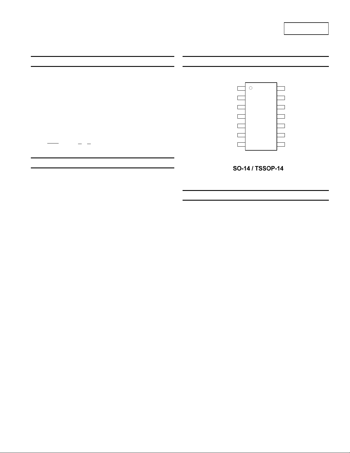
Pin Assignments
74LVC00A
QUADRUPLE 2-INPUT NAND GATES
(Top View)
1A
1B
1Y
2A
2B
2Y
GND
1
2
3
4
5
6
7
14
Vcc
13
4B
12
4A
11
4Y
10
3B
9
3A
8
3Y
• Supply Voltage Range from 1.65V to 5.5V
• Sinks 24mA at V
• CMOS low power consumption
• IOFF Supports Partial-Power-Down Mode Operation
• Inputs or outputs accept up to 5.5V
• Inputs can be driven by 3.3V or 5.5V allowing for voltage
translation applications.
• ESD Protection Exceeds JESD 22
200-V Machine Model (A115-A)
2000-V Human Body Model (A114-A)
Exceeds 1000-V Charged Device Model (C101C)
• Latch-Up Exceeds 250mA per JESD 78, Class II
• Range of Package Options SO-14 and TSSOP-14
• Totally Lead-Free & Fully RoHS Compliant (Notes 1 & 2)
• Halogen and Antimony Free. “Green” Device (Note 3)
Notes: 1. No purposely added lead. Fully EU Directive 2002/95/EC (RoHS) & 2011/65/EU (RoHS 2) compliant.
2. See http://www.diodes.com for more information about Diodes Incorporated’s definitions of Halogen- and Antimony-free, "Green" and Lead-free.
3. Halogen- and Antimony-free "Green” products are defined as those which contain <900ppm bromine, <900ppm chlorine (<1500ppm total Br + Cl) and
<1000ppm antimony compounds.
74LVC00A
Document number: DS35257 Rev. 3 - 2
= 3.3V
CC
Applications
• Voltage Level Shifting
• General Purpose Logic
• Power Down Signal Isolation
• Wide array of products such as:
PCs, networking, notebooks, ultrabooks, netbooks
Computer peripherals, hard drives, CD/DVD ROM
TV, DVD, DVR, set top box
1 of 9
www.diodes.com
© Diodes Incorporated
June 2012
Page 2
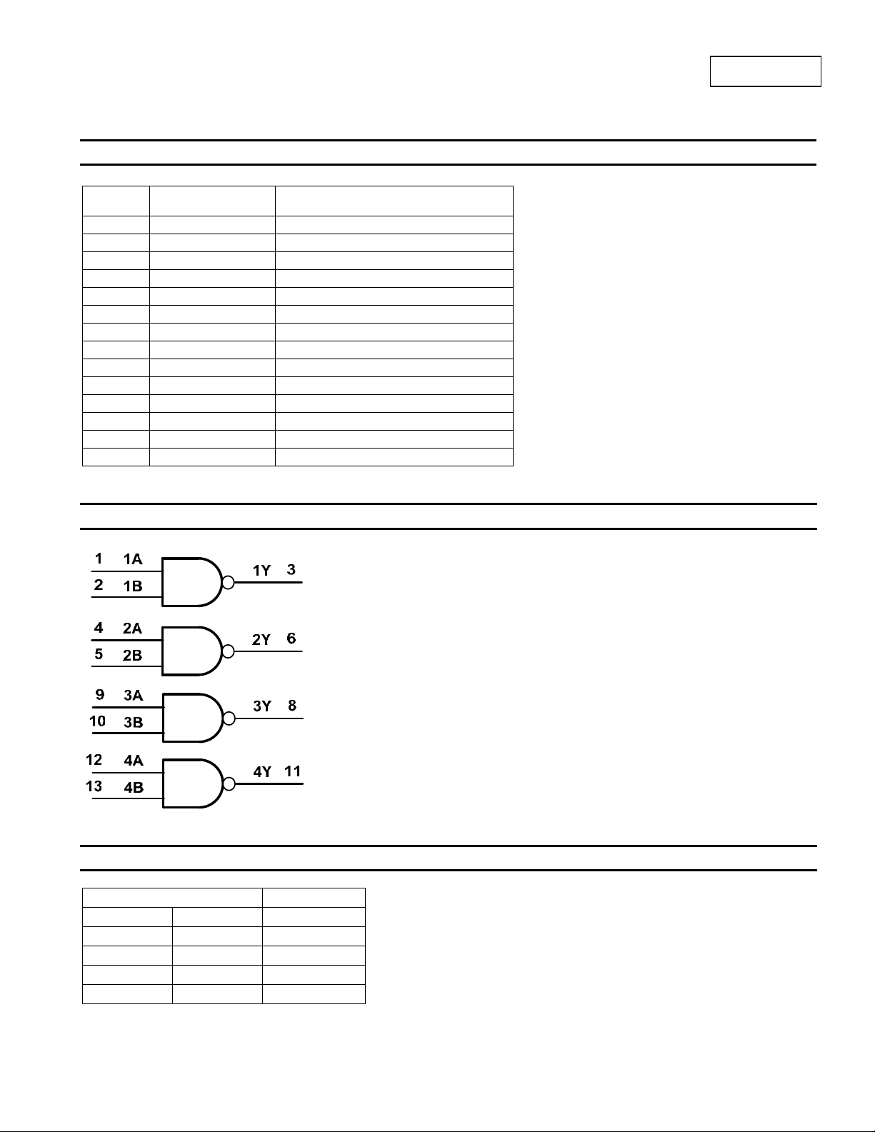
Pin Descriptions
Pin
Number
1 1A
2 1B Data Input
3 1Y Data Output
4
5 2B Data Input
6 2Y Data Output
7 GND Ground
8 3Y Data Output
9 3A Data Input
10 3B Data Input
11 4Y Data Output
12 4A Data Input
13 4B Data Input
14
Pin Name Function
Data Input
V
2A
CC
Data Input
Supply Voltage
Logic Diagram
74LVC00A
Fuction Table
Inputs Output
A B Y
L L H
L H H
H L H
H H L
74LVC00A
Document number: DS35257 Rev. 3 - 2
2 of 9
www.diodes.com
June 2012
© Diodes Incorporated
Page 3
74LVC00A
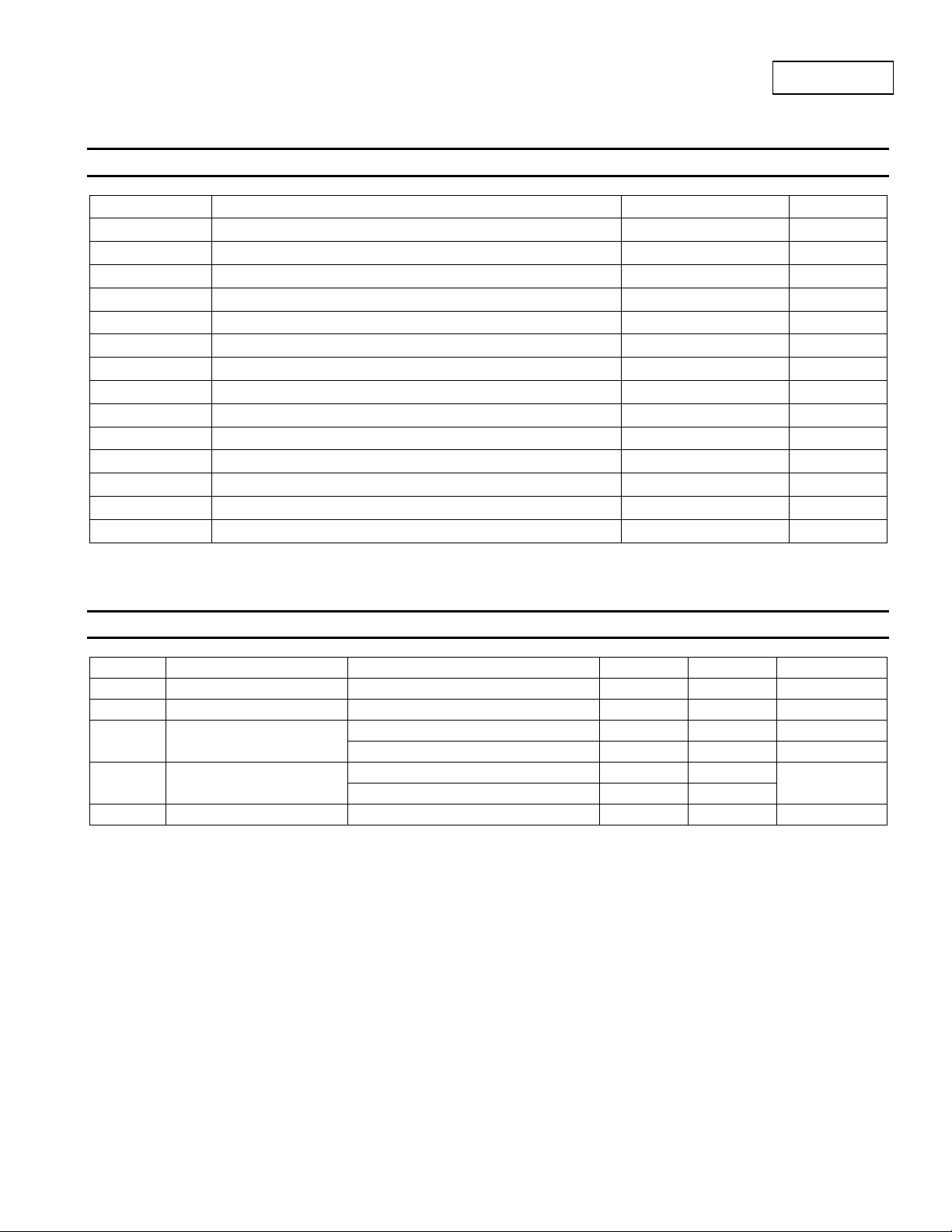
Absolute Maximum Ratings (Note 4) (@T
Symbol Parameter Rating Unit
ESD HBM Human Body Model ESD Protection 2 KV
ESD CDM Charged Device Model ESD Protection 1 KV
ESD MM Machine Model ESD Protection 200 V
VCC
VI
VO Voltage applied to output in high impedance or I
VO
IIK Input Clamp Current VI < 0
IOK
IO
ICC,, I
GND
TJ
T
STG
P
TOT
Note: 4. Stresses beyond the absolute maximum may result in immediate failure or reduced reliability. These are stress values and device operation should
be within recommend values.
Supply Voltage Range -0.5 to 6.5 V
Input Voltage Range -0.5 to 6.5 V
Voltage applied to output in high or low state
Output Clamp Current V
Continuous output current ±50 mA
Continuous current through Vcc or GND ±100 mA
Operating Junction Temperature -40 to 150 °C
Storage Temperature -65 to 150 °C
Total Power Dissipation 500 mW
< 0
O
Recommended Operating Conditions (Note 5) (@T
Symbol Parameter Conditions Min Max Unit
VCC
VI
VO
Δt/ΔV Input transition rise or fall rate
TA
Notes: 5. Unused inputs should be held at VCC or Ground.
Supply Voltage 1.65 5.5 V
Input Voltage 0 5.5 V
Output Voltage
Operating free-air temperature -40 +125 °C
Active Mode 0
VCC= 0V; Power Down Mode
= 1.65V to 2.7V
V
CC
VCC = 2.7V to 3.6V
= +25°C, unless otherwise specified.)
A
state
OFF
= +25°C, unless otherwise specified.)
A
-0.5 to 6.5 V
-0.3 to VCC +0.5
-50 mA
-50 mA
V
CC
0 5.5 V
20
10
V
V
ns/V
74LVC00A
Document number: DS35257 Rev. 3 - 2
3 of 9
www.diodes.com
June 2012
© Diodes Incorporated
Page 4
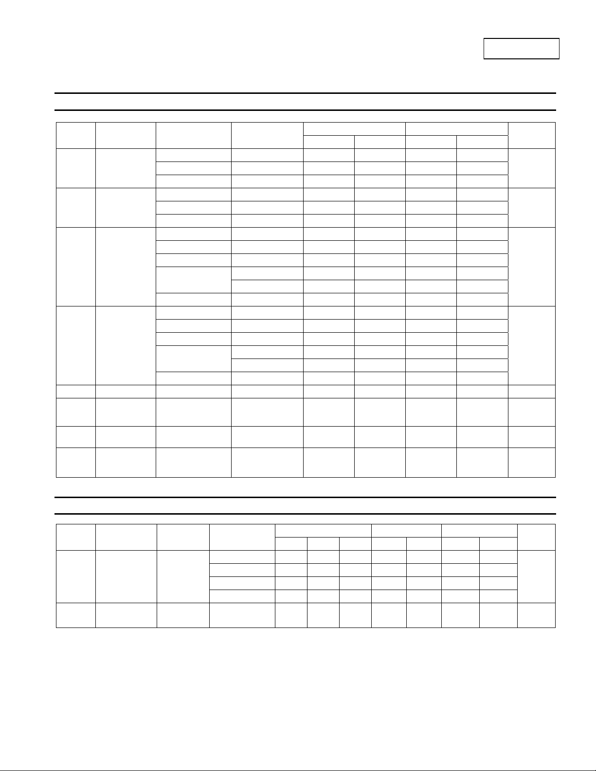
Electrical Characteristics (@T
= +25°C, unless otherwise specified.)
A
Symbol Parameter Test Conditions VCC
1.65V to 1.95V
2.3V to 2.7V 1.7 1.6
2.7 V to 3.6V 2.0 2.0
1.65V to 1.95V
2.3V to 2.7V 0.7 0.7
2.7V to 3.6V 0.8 0.8
I
= -100μA
OH
IOH = -4mA
IOH = -8mA
IOH = -12mA
IOH = -24mA
I
= 100μA
OH
IOH = 4mA
IOH = 8mA
IOH = 12mA
IOH =-24mA
VI = GND to 5.5V
V
or VO = 0V
I
to 3.6V
= GND or VCC
V
I
I
=0
O
One input at V
0.6V Other at Vcc or
Gnd.
CC
1.65V to 3.6V
1.65V 1.2
2.3V 1.9
2.7V 2.2 2.05
3.0V 2.3 2.1
3.0V 2.2 2.0
1.65V to 3.6V 0.2 0.3
1.65V 0.45 0.6
2.3V 0.70 0.85
2.7V 0.40 0.6
3.0V 0.55 0.6
3.0V 0.55 0.6
3.6V ±5 ±20 μA
3.6V 10
–
2.7V to 3.6V 500
V
IH
VIL
VOH
VOL
II
I
OFF
ICC
ΔICC
High-level Input
Voltage
Low-level input
voltage
High Level
Output Voltage
High-level
Output Voltage
Input Current
Power Down
Leakage
Current
Supply Current
Additional
Supply Current
Switching Characteristics
Symbol Parameter
Propagation
tPD
t
SK(0)
Delay A
Output Skew
N
to YN
Time
or B
Test
Conditions
Figure 1
N
VCC
1.65V to1.95V 1.0 6.0 12.0 1.0 12.5 1.0 14.0
2.3V to 2.7V 1.0 4.6 5.9 1.0 6.4 1.0 7.9
2.7V 1.0 4.3 4.9 1.0 5.1 1.0 6.5
3V to 3.6V 1.0 3.5 4.1 1.0 4.3 1.0 5.5
3V to 3.6V 1.0 1.5 ns
74LVC00A
Document number: DS35257 Rev. 3 - 2
74LVC00A
T
= -40°C to +85°C TA = -40°C to +125°C
A
Min Max Min Max
0.65 X V
V
CC
0 10 20 μA
= 25°C -40°C to 85°C -40°C to 125°C
T
A
– 0.2
CC
0.35 X V
CC
0.65 X VCC
V
– 0.3
CC
40
0.35 X VCC
5000 μA
Min Typ Max Min Max Min Max
4 of 9
www.diodes.com
Unit
V
V
V
V
μA
Unit
June 2012
© Diodes Incorporated
ns
Page 5
74LVC00A
Operating Characteristics (@T
= +25°C, unless otherwise specified.)
A
Parameter Test Conditions
Cpd
CI
Power dissipation
capacitance per gate
Input Capacitance
VI = V
CC
Typ Typ Typ
f = 10 MHz 17 17 18 pF
– or GND
CC
4 4 4 pF
Unit
= 1.8V VCC = 2.5V VCC = 3.3V
V
Package Characteristics
Symbol Parameter
θ
JA
θ
JC
Note: 6. Test condition for SO-14 and TSSOP-14 : Device mounted on FR-4 substrate PC board, 2oz copper, with minimum recommended pad layout.
Thermal Resistance
Junction-to-Ambient
Thermal Resistance
Junction-to-Case
Test Conditions
SO-14
TSSOP-14 159
SO-14
TSSOP-14 25
V
CC
(Note 6)
(Note 6)
Min Typ Max Unit
TBD
TBD
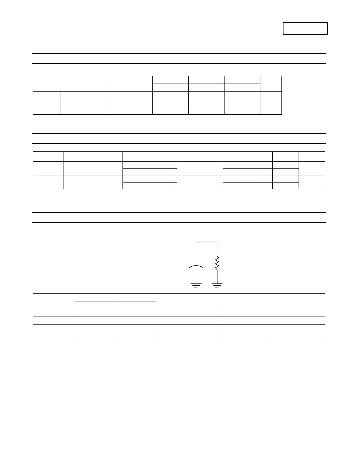
Parameter Measuement Information
From Output
Under Test
CL
(see Note A)
RL
VCC
1.8V±0.15V
2.5V±0.2V
2.7V 2.7V ≤2.5ns 1.5V 50pF 500Ω
3.3V±0.3V 2.7V ≤2.5ns 1.5V 50pF 500Ω
V
V
Inputs
VI t
CC
CC
r/tf
≤2ns
≤2ns
VM C
VCC/2
VCC/2
R
L
30pF 1KΩ
30pF 500Ω
L
o
C/W
o
C/W
74LVC00A
Document number: DS35257 Rev. 3 - 2
5 of 9
www.diodes.com
June 2012
© Diodes Incorporated
Page 6
74LVC00A
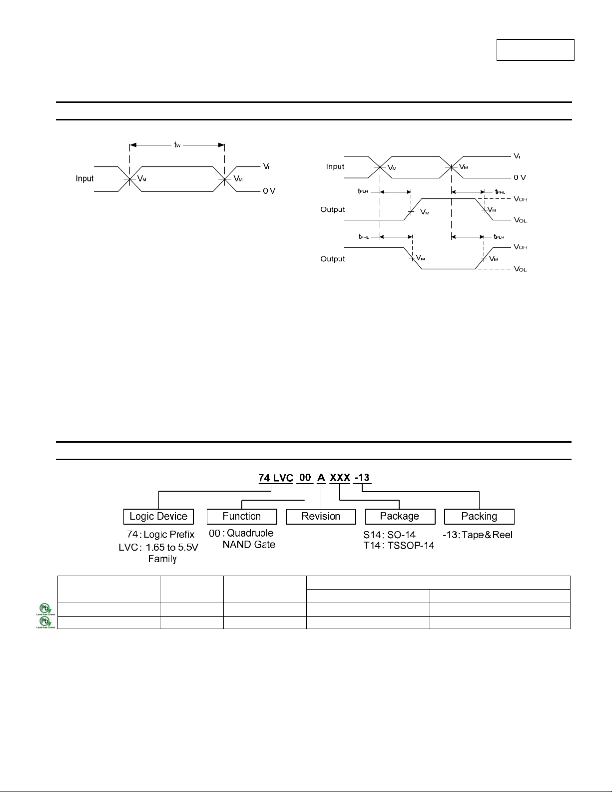
Parameter Measuement Information
(cont.)
Voltage Waveform
Pulse Duration
Notes: A . Includes test lead and test apparatus capacitance.
B. All pulses are supplied at pulse repetition rate ≤ 10 MHz
C. Inputs are measured separately one transition per measurement
D. t
PLH
and t
PHL
are the same as t
PD
Figure 1. Load Circuit and Voltage Waveforms
Voltage Waveform
Propagation Delay Times
Inverting and Non Inverting Outputs
Ordering Information
Part
Number
74LVC00AS14-13 S14 SO-14 2500/Tape & Reel -13
74LVC00AT14-13 T14 TSSOP-14 2500/Tape & Reel -13
Notes: 7. The taping orientation and tape details can be found at http://www.diodes.com/datasheets/ap02007.pdf
Package
Code
Packaging
(Note 7)
Quantity Part Number Suffix
13” Tape and Reel
74LVC00A
Document number: DS35257 Rev. 3 - 2
6 of 9
www.diodes.com
June 2012
© Diodes Incorporated
Page 7
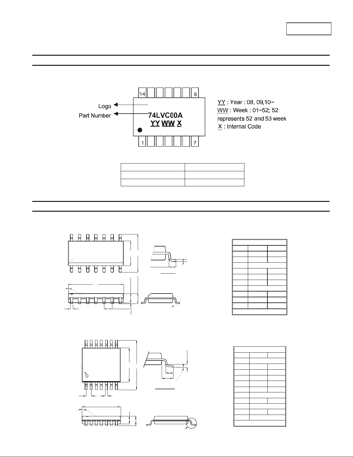
Marking Information
(1) SO-14, TSSOP-14
Part Number Package
74LVC00AS14 SO-14
74LVC00AT14 TSSOP-14
Package Outline Dimensions (All dimensions in mm.)
Package Type: SO-14
H
E
Gauge Plane
L
Detail “A”
7°
(
4x
D
)
A2
A
B
e
A1
Detail “A”
Package Type: TSSOP-14
74LVC00A
Document number: DS35257 Rev. 3 - 2
Pin# 1 Indent
B
L
G
K
A
a
1
D
C
F1
F
Detail ‘A’
Detail ‘A’
7 of 9
www.diodes.com
θ
5
2
.
0
2
a
Gauge Plane
Seating Plane
SO-14
Dim Min Max
A 1.47 1.73
A1 0.10 0.25
A2 1.45 Typ
B 0.33 0.51
D 8.53 8.74
E 3.80 3.99
e 1.27 Typ
H 5.80 6.20
L 0.38 1.27
0° 8°
θ
All Dimensions in mm
TSSOP-14
Dim Min Max
a1 7° (4X)
a2
F1 0.45 0.75
All Dimensions in mm
0°
A 4.9 5.10
B 4.30 4.50
C
⎯
D 0.8 1.05
F 1.00 Typ
G 0.65 Typ
K 0.19 0.30
L 6.40 Typ
8°
1.2
74LVC00A
June 2012
© Diodes Incorporated
Page 8
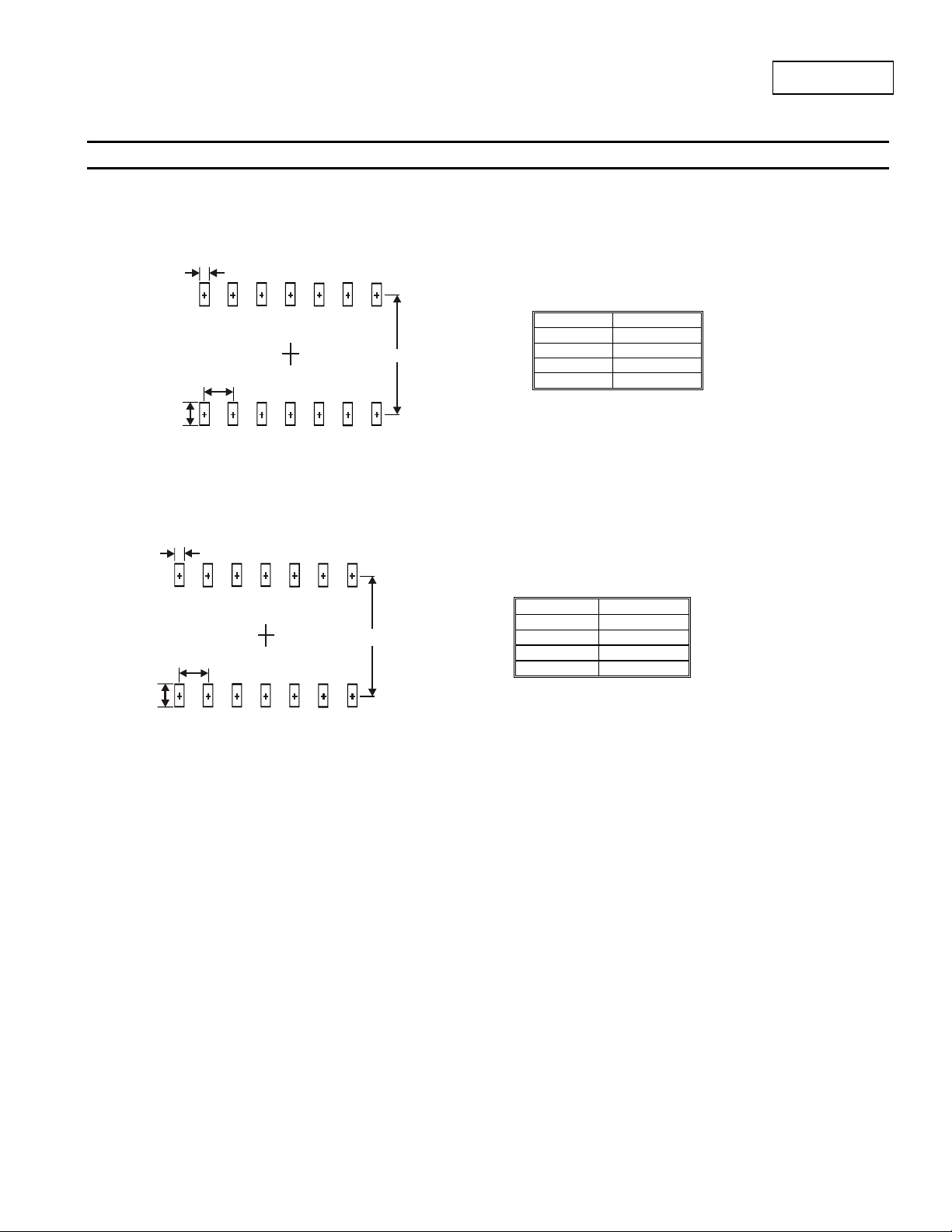
Suggested Pad Layout
Package Type: SO-14
Package Type: TSSOP-14
X
C2
Y
X
C2
Y
74LVC00A
Dimensions Value (in mm)
X 0.60
C1
Y 1.50
C1 5.4
C2 1.27
Dimensions Value (in mm)
C1
X 0.45
Y 1.45
C1 5.9
C2 0.65
74LVC00A
Document number: DS35257 Rev. 3 - 2
8 of 9
www.diodes.com
June 2012
© Diodes Incorporated
Page 9

74LVC00A
DIODES INCORPORATED MAKES NO WARRANTY OF ANY KIND, EXPRESS OR IMPLIED, WITH REGARDS TO THIS DOCUMENT,
INCLUDING, BUT NOT LIMITED TO, THE IMPLIED WARRANTIES OF MERCHANTABILITY AND FITNESS FOR A PARTICULAR PURPOSE
(AND THEIR EQUIVALENTS UNDER THE LAWS OF ANY JURISDICTION).
Diodes Incorporated and its subsidiaries reserve the right to make modifications, enhancements, improvements, corrections or other changes
without further notice to this document and any product described herein. Diodes Incorporated does not assume any liability arising out of the
application or use of this document or any product described herein; neither does Diodes Incorporated convey any license under its patent or
trademark rights, nor the rights of others. Any Customer or user of this document or products described herein in such applications shall assume
all risks of such use and will agree to hold Diodes Incorporated and all the companies whose products are represented on Diodes Incorporated
website, harmless against all damages.
Diodes Incorporated does not warrant or accept any liability whatsoever in respect of any products purchased through unauthorized sales channel.
Should Customers purchase or use Diodes Incorporated products for any unintended or unauthorize d application, Customers shall indemnify and
hold Diodes Incorporated and its representatives harmless against all claims, damages, expenses, and attorney fees arising out of, directly or
indirectly, any claim of personal injury or death associated with such unintended or unauthorized application.
Products described herein may be covered by one or more United States, international or foreign patents pending. Product names and markings
noted herein may also be covered by one or more United States, international or foreign trademarks.
Diodes Incorporated products are specifically not authorized for use as critical components in life support devices or systems without the express
written approval of the Chief Executive Officer of Diodes Incorporated. As used herein:
A. Life support devices or systems are devices or systems which:
1. are intended to implant into the body, or
2. support or sustain life and whose failure to perform when properly used in accordance with instructions for use provided in the
labeling can be reasonably expected to result in significant injury to the user.
B. A critical component is any component in a life support device or system whose failure to perform can be reasonably expected to cause the
failure of the life support device or to affect its safety or effectiveness.
Customers represent that they have all necessary expertise in the safety and regulatory ramifications of their life support devices or systems, and
acknowledge and agree that they are solely responsible for all legal, regulatory and safety-related requirements concerning their products and any
use of Diodes Incorporated products in such safety-critical, life support devices or systems, notwithstanding any devices- or systems-related
information or support that may be provided by Diodes Incorporated. Further, Customers must fully indemnify Diodes Incorporated and its
representatives against any damages arising out of the use of Diodes Incorporated products in such safety-critical, life support devices or systems.
Copyright © 2012, Diodes Incorporated
www.diodes.com
IMPORTANT NOTICE
LIFE SUPPORT
74LVC00A
Document number: DS35257 Rev. 3 - 2
9 of 9
www.diodes.com
June 2012
© Diodes Incorporated
 Loading...