

Page 1
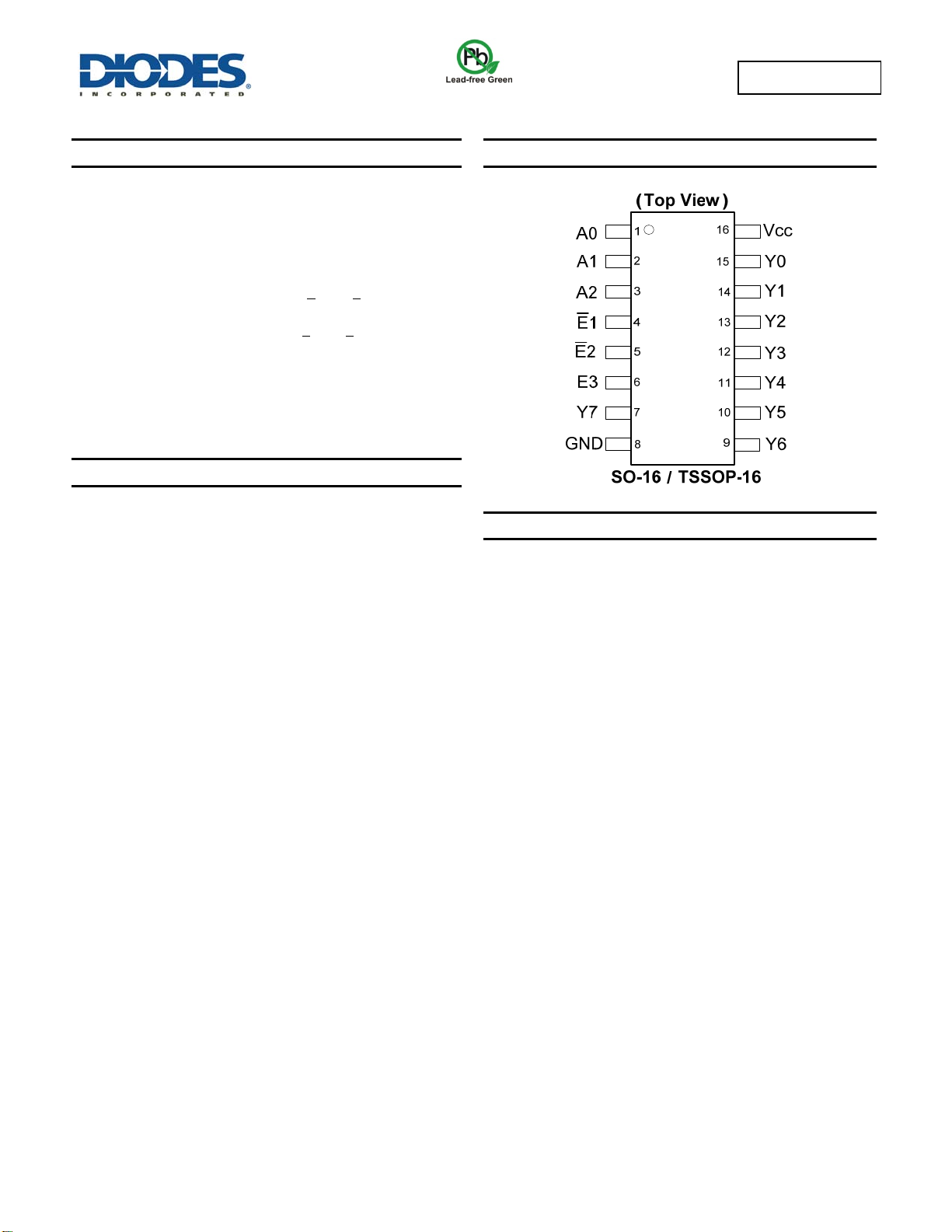
Description
The 74AHCT138 is an advanced high speed CMOS device that is
designed to be pin compatable with 74LS low power Schottky types.
The device accepts a three bit binary weighted address on input pins
A0, A1 and A2 and when enabled will produce one active low output
with the remaining seven being high.
There are two active LOW enable inputs E
HIGH enable input E3. The disabled device state results in all outputs
being high. The enable state occurs with E
E3 asserted high.
The multiple enable lines allow for the parallel expansion of decoders
to create 4-to-16 line versions with no additional parts and 5-to-32
versions with the addition of a single inverter.
1 and E2, and one active
1 and E2 asserted low and
74AHCT138
3 TO 8 LINE DECODER DEMULTIPLEXER
Pin Assignments
Features
Supply Voltage Range from 4.5V to 5.5V
Sinks or Sources 8mA at V
CMOS Low Power Consumption
Schmitt Trigger Action at All Inputs
Inputs Accept up to 6.0V
ESD Protection Tested per JESD 22
Exceeds 200-V Machine Model (A115-A)
Exceeds 2000-V Human Body Model (A114-A)
Exceeds 1000-V Charged Device Model (C101C)
Latch-Up Exceeds 250mA per JESD 78, Class II
Totally Lead-Free & Fully RoHS Compliant (Notes 1 & 2)
Halogen and Antimony Free. “Green” Device (Note 3)
Notes: 1. No purposely added lead. Fully EU Directive 2002/95/EC (RoHS) & 2011/65/EU (RoHS 2) compliant.
2. See http://www.diodes.com for more information about Diodes Incorporated’s definitions of Halogen- and Antimony-free, "Green" and Lead-free.
3. Halogen- and Antimony-free "Green” products are defined as those which contain <900ppm bromine, <900ppm chlorine (<1500ppm total Br + Cl) and
<1000ppm antimony compounds.
= 4.5V
CC
Click here for ordering information, located at the end of datasheet
Applications
Memory chip select decoding
Demultiplexing
Single line peripheral control
Allow simple serial bit streams from a microcontroller to control as
many peripheral lines as needed
74AHCT138
Document number: DS35483 Rev. 2 - 2
1 of 9
www.diodes.com
June 2013
© Diodes Incorporated
Page 2
74AHCT138
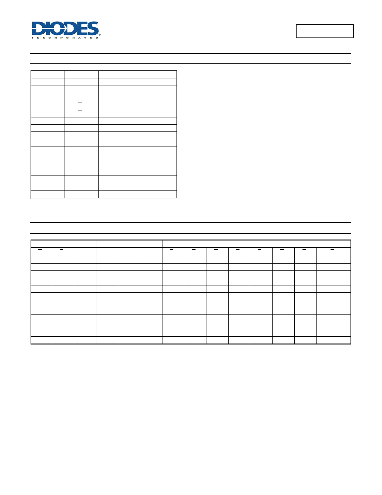
Pin Descriptions
Pin Number Pin Name Description
1 A0 Address Input 0
2 A1 Address Input 1
3 A2 Address Input 2
4
5
6 E3 Enable Input 3 (active HIGH)
7 Y7 Output 7 (active LOW)
8 GND Ground
9 Y6 Output 6 (active LOW)
10 Y5 Output 5 (active LOW)
11 Y4 Output 4 (active LOW)
12 Y3 Output 3 (active LOW)
13 Y2 Output 2 (active LOW)
14 Y1 Output 1 (active LOW)
15 Y0 Output o (active LOW)
16
1
E
2
E
V
CC
Enable Input 1 (active LOW)
Enable Input 2 (active LOW)
Supply Voltage
Function Table Diagram
Control Input Output
E1 E2
H X X X X X H H H H H H H H
X H X
X X L
L L H
74AHCT138
Document number: DS35483 Rev. 2 - 2
E3 A2 A1 A0
L L L H H H H H H H L
L L H H H H H H H L H
L H L H H H H H L H H
L H H H H H H L H H H
H L L H H H L H H H H
H L H H H L H H H H H
H H L H L H H H H H H
H H H L H H H H H H H
Y7 Y6 Y5 Y4 Y3 Y2 Y1 Y0
2 of 9
www.diodes.com
June 2013
© Diodes Incorporated
Page 3
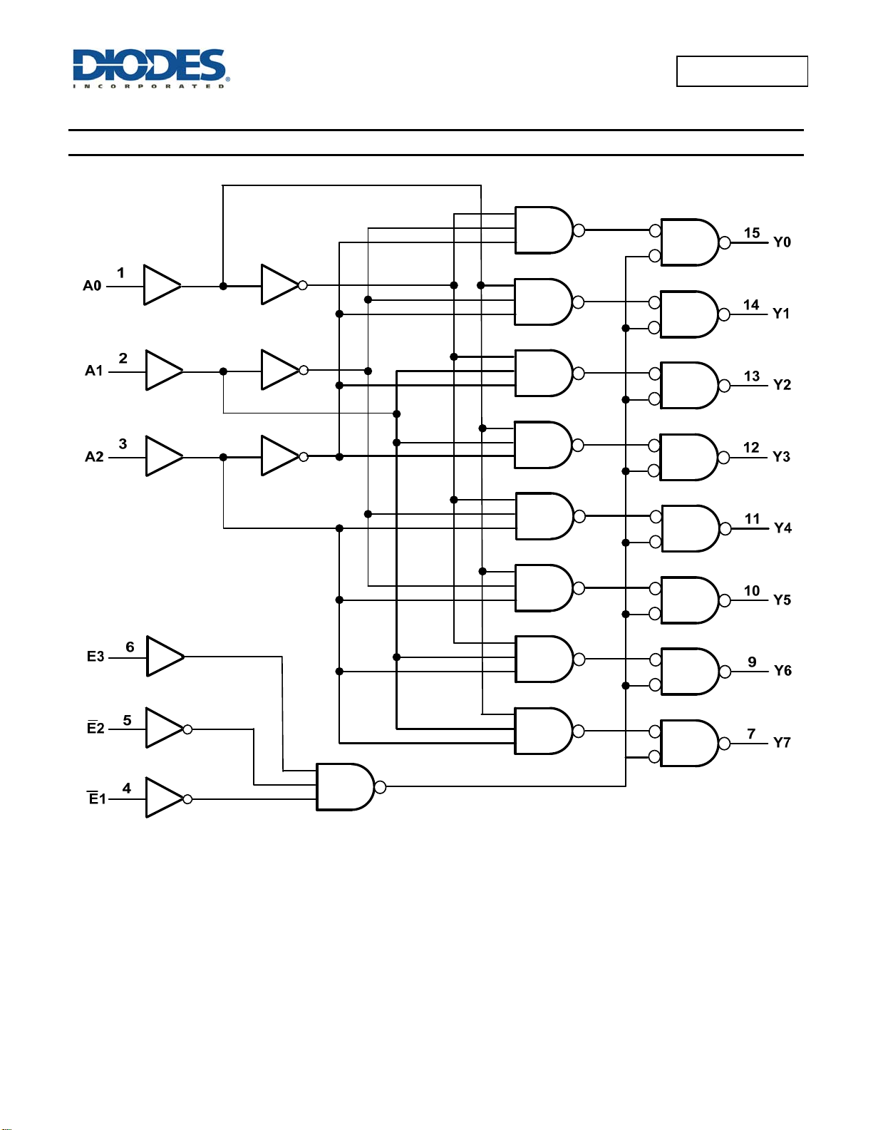
Logic Diagram
74AHCT138
74AHCT138
Document number: DS35483 Rev. 2 - 2
3 of 9
www.diodes.com
June 2013
© Diodes Incorporated
Page 4
74AHCT138
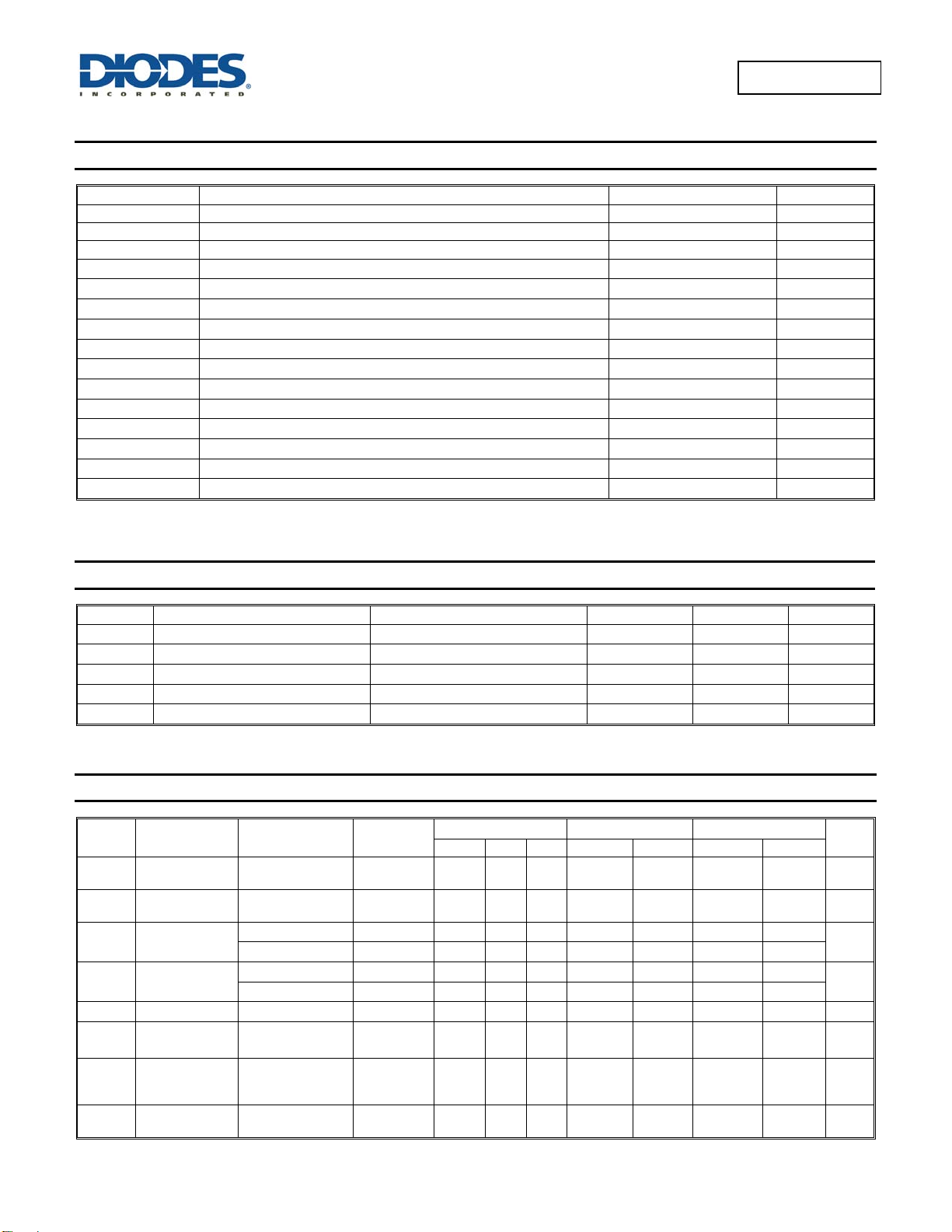
Absolute Maximum Ratings (Note 4) (@T
= +25°C, unless otherwise specified.)
A
Symbol Description Rating Unit
ESD HBM Human Body Model ESD Protection 2 KV
ESD CDM Charged Device Model ESD Protection 1 KV
ESD MM Machine Model ESD Protection 200 V
VCC
VI
Vo
IIK Input Clamp Current VI< -0.5V
IOK Output Clamp Current VO<-0.5V
IOK Output Clamp Current VO> VCC + 0.5V
IO
ICC Continuous current through VDD or GND
I
Continuous current through VDD or GND
GND
TJ
T
STG
P
TOT
Notes: 4. Stresses beyond the absolute maximum may result in immediate failure or reduced reliability. These are stress values and device operation should be
within recommend values.
Supply Voltage Range -0.5 to +7.0 V
Input Voltage Range -0.5 to +7.0 V
Voltage applied to output in high or low state
-0.3 to VCC +0.5
V
-20 mA
-20 mA
25 mA
Continuous output current +/- 25 mA
75 mA
-75 mA
Operating Junction Temperature -40 to +150 °C
Storage Temperature -65 to +150 °C
Total Power Dissipation 500 mW
Recommended Operating Conditions (Note 5) (@T
= +25°C, unless otherwise specified.)
A
Symbol Parameter Conditions Min Max Unit
VCC
VI
VO
t/V
TA
Note: 5. Unused inputs should be held at VCC or Ground.
Supply Voltage 4.5 5.5 V
Input Voltage 0 5.5 V
Output Voltage Active Mode 0
Input transition Rise or Fall Rate
V
= 4.5V to 5.5V
CC
VCC
20 ns/V
V
Operating Free-Air Temperature -40 +125 °C
Electrical Characteristics (@T
= +25°C, unless otherwise specified.)
A
Symbol Parameter Test Conditions
V
IH
VIL
VOH
VOL
II
ICC
∆ICC
Ci
High-level Input
Voltage
Low-level input
voltage
High Level
Output Voltage
Low-level Output
Voltage
Input Current
Supply Current
Additional
Supply Current
per Input
Input
Capacitance
4.5V to 5.5V 2.0
4.5V to 5.5V
= -50μA
I
OH
IOH = -8mA
= 50μA
I
OL
IOL = 8mA
VI = GND or 5.5V
= GND or VCC
V
I
I
= 0
O
= Vcc -2.1V
V
I
= 0
I
O
V
= V
or GND
i
CC
V
CC
A
Min Typ Max Min Max Min Max
4.5V 4.4 4.5
4.5V 3.94
4.5V
4.5V
0V to 5.5V
5.5V
4.5V to 5.5V
5.5V
0.1 ±0.1
0 0.1
4 10
0.8
0.36
4.0
1.35
2.0
4.4
3.80
0.8
0.1
0.44
± 1
40
1.5
10
2.0
4.4
3.70
0.8 V
0.1
0.55
± 2 μA
80 μA
1.5 mA
10 pF
Unit
V
V
V
= +25°C TA = -40°C to +85°C TA = -40°C to +125°C
T
74AHCT138
Document number: DS35483 Rev. 2 - 2
4 of 9
www.diodes.com
June 2013
© Diodes Incorporated
Page 5
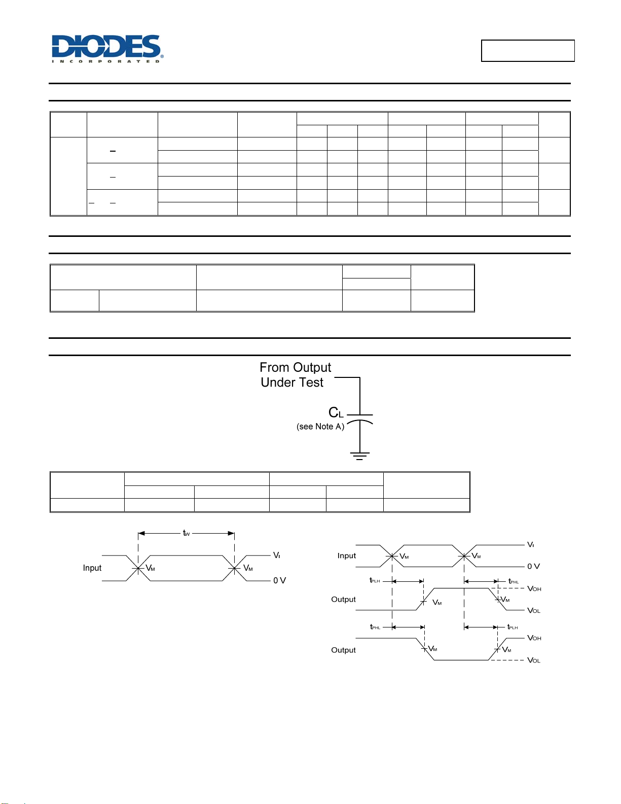
Switching Characteristics
Symbol Parameter Test Conditions
Propagation Delay
n
An to Y
Propagation Delay
tPD
n
E3 to Y
Propagation Delay
n to Yn
E
Figure 2 C
Figure 2 CL = 50pF
Figure 2 C
Figure 2 CL = 50pF
Figure 2 C
Figure 2 CL = 50pF
=15pF
L
= 15pF
L
= 15pF
L
Operating Characteristics (@T
Parameter
Cpd
Power dissipation
capacitance
f = 1 MHz all outputs switching-no load 23 pF
= +25°C
T
V
CC
4.5V to 5.5V 0.5 4.4 10.4 1.0 12.0 1.0 13.0
4.5V to 5.5V 0.5 6.2 11.4 1.0 13.0 1.0 14.5
4.5V to 5.5V 0.5 4.3 9.1 1.0 10.5 1.0 11.5
4.5V to 5.5V 0.5 6.2 10.1 1.0 11.5 1.0 13.0
4.5V to 5.5V 0.5 4.3 9.6 1.0 11.0 1.0 12.0
4.5V to 5.5V 0.5 6.2 10.6 1.0 12.0 1.0 13.5
= +25°C, unless otherwise specified.)
A
Test
Conditions
A
Min Typ Max Min Max Min Max
V
CC
-40°C to +85°C -40°C to +125°C
= 5V
Typ
Unit
74AHCT138
Unit
ns
ns
ns
Parameter Measurement Information
V
CC
4.5V to 5.5V 3.0 V 3ns 1.5 V
Inputs
VI t
r/tf
Input Output
Voltage Waveform
Pulse Duration
V
M
V
/2
CC
C
L
15pF, 50pF
Notes: A. Includes test lead and test apparatus capacitance.
B. All pulses are supplied at pulse repetition rate ≤ 10 MHz.
C. Inputs are measured separately one transition per measurement.
D. t
74AHCT138
Document number: DS35483 Rev. 2 - 2
PLH
and t
are the same as tPD.
PHL
5 of 9
www.diodes.com
Voltage Waveform
Propagation Delay Times
Inverting and Non Inverting Outputs
June 2013
© Diodes Incorporated
Page 6
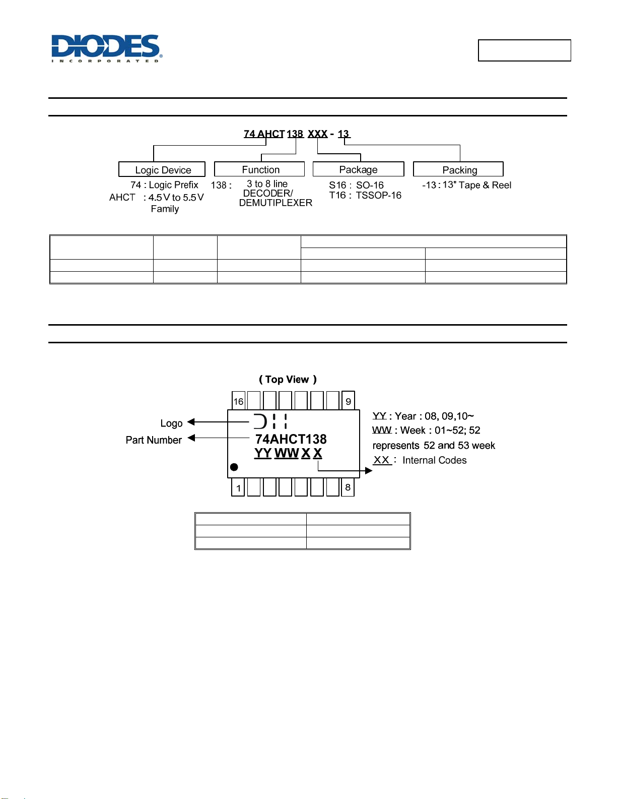
Ordering Information
74AHCT138
Figure 1. Load Circuit and Voltage Waveforms
Part Number Package Code Packaging
74AHCT138S16-13 S16 SO-16 2500/Tape & Reel -13
74AHCT138T16-13 T16 TSSOP-16 2500/Tape & Reel -13
Notes: 7. The taping orientation is located on our website at http://www.diodes.com/datasheets/ap02007.pdf
Quantity Part Number Suffix
7” Tape and Reel (Note 7)
Marking Information
(1) SO-16, TSSOP16
Part Number Package
74AHCT138S16 SO-16
74AHCT138T16 TSSOP-16
74AHCT138
Document number: DS35483 Rev. 2 - 2
6 of 9
www.diodes.com
June 2013
© Diodes Incorporated
Page 7
74AHCT138
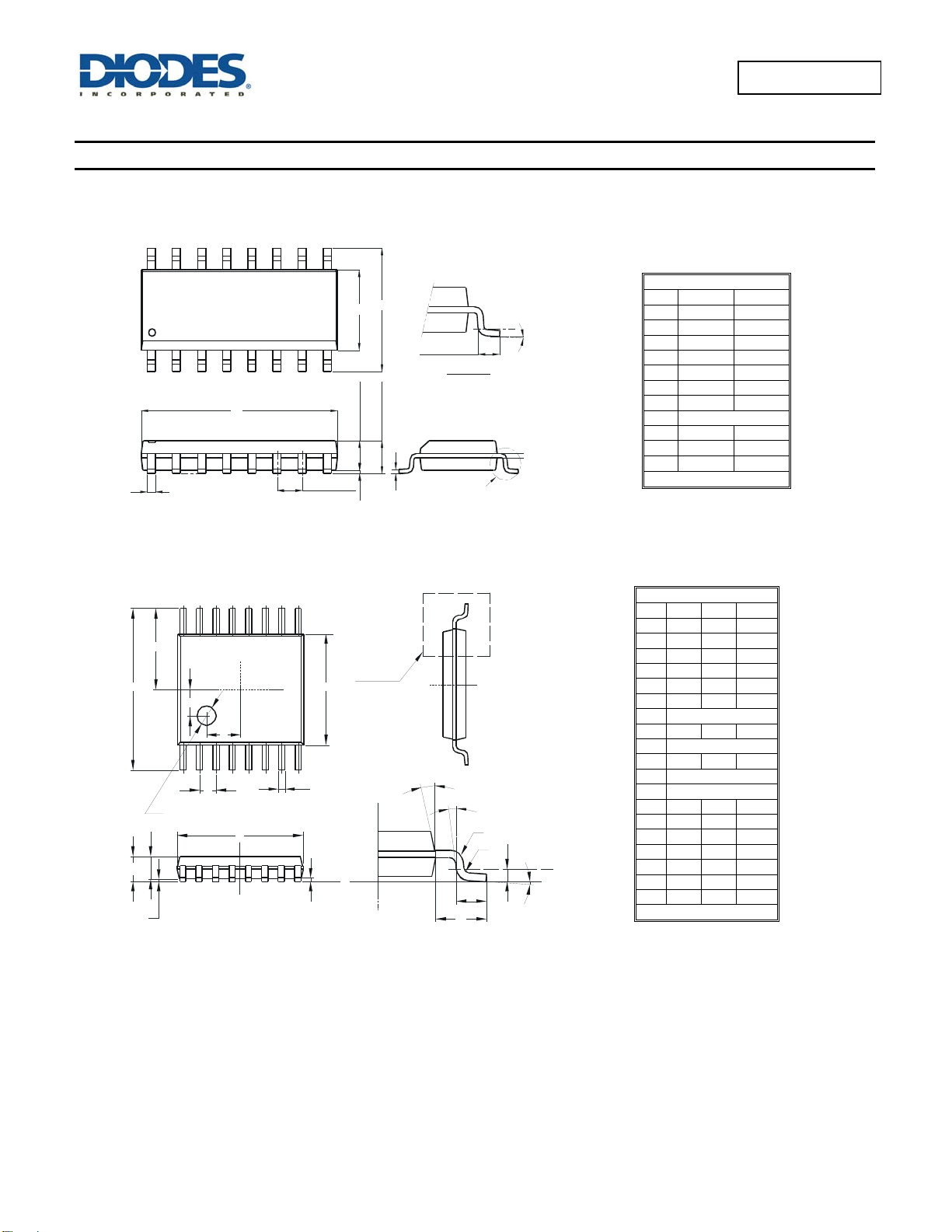
Package Outline Dimensions (All dimensions in mm.)
Please see AP02002 at http://www.diodes.com/datasheets/ap02002.pdf for latest version.
Package Type: SO-16
H
E
L
Detail ‘A’
Gauge Plane
Dim Min Max
D
A2
A
B
e
A1
C
Detail ‘A’
Package Type: TSSOP-16
E/2
E
A
A1
Y
PIN 1
Ø0.760Depth0.050±0.02
A2
SEE DETAIL 'A'
E1
X
L1
DETAIL 'A'
x)
R1
L2
R
GAUGE
PLANE
L
e
D
b
C
SEATING PLANE
74AHCT138
Document number: DS35483 Rev. 2 - 2
7 of 9
www.diodes.com
Dim Min Max Typ
A - 1.08 A1 0.05 0.15 -
A2 0.80 0.93 -
b 0.19 0.30 -
c 0.09 0.20 -
D 4.90 5.10 -
E 6.40 BSC
E1 4.30 4.50 -
e 0.65 BSC
L 0.45 0.75 -
L1 1.00 REF
L2 0.25 BSC
R 0.09 - -
R1 0.09 - -
X - - 1.350
Y - - 1.050
Θ
Θ1 5° 15° -
Θ2 0° - -
All Dimensions in mm
SO-16
A 1.40 1.75
A1 0.10 0.25
A2 1.30 1.50
B 0.33 0.51
C 0.19 0.25
D 9.80 10.00
E 3.80 4.00
e 1.27 Typ
H 5.80 6.20
L 0.38 1.27
Θ
0 8
All Dimensions in mm
TSSOP-16
0° 8° -
© Diodes Incorporated
June 2013
Page 8
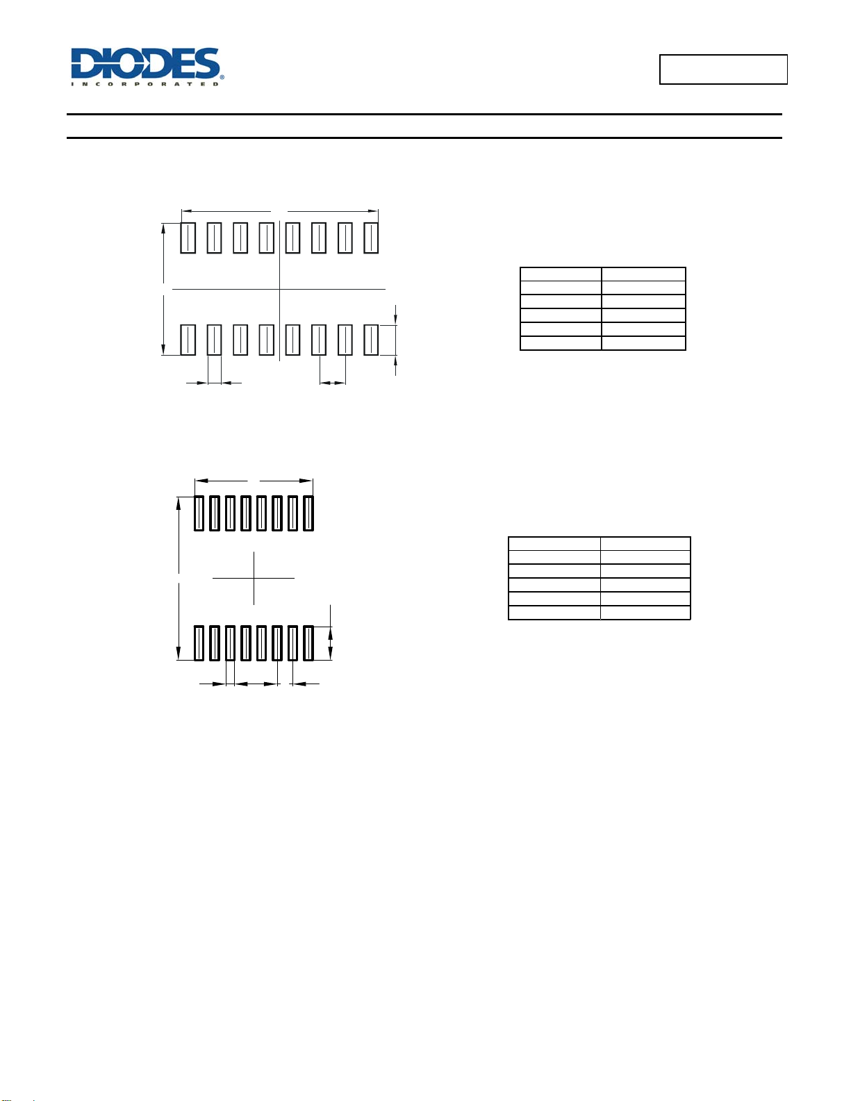
Suggested Pad Layout
Please see AP02001 at http://www.diodes.com/datasheets/ap02001.pdf for the latest version.
Package Type: SO-16
X1
Y1
Pin 1
Y
X
C
Package Type: TSSOP-16
X1
Y1
1
X (16x)
74AHCT138
Document number: DS35483 Rev. 2 - 2
Y (16x)
C
8 of 9
www.diodes.com
Dimensions Value (in mm)
C 1.270
X 0.670
X1 9.560
Y 1.450
Y1 6.400
Dimensions Value (in mm)
C 0.650
X 0.350
X1 4.900
Y 1.400
Y1 6.800
74AHCT138
June 2013
© Diodes Incorporated
Page 9
74AHCT138
DIODES INCORPORATED MAKES NO WARRANTY OF ANY KIND, EXPRESS OR IMPLIED, WITH REGARDS TO THIS DOCUMENT,
INCLUDING, BUT NOT LIMITED TO, THE IMPLIED WARRANTIES OF MERCHANTABILITY AND FITNESS FOR A PARTICULAR PURPOSE
(AND THEIR EQUIVALENTS UNDER THE LAWS OF ANY JURISDICTION).
Diodes Incorporated and its subsidiaries reserve the right to make modifications, enhancements, improvements, corrections or other changes
without further notice to this document and any product described herein. Diodes Incorporated does not assume any liability arising out of the
application or use of this document or any product described herein; neither does Diodes Incorporated convey any license under its patent or
trademark rights, nor the rights of others. Any Customer or user of this document or products described herein in such applications shall assume
all risks of such use and will agree to hold Diodes Incorporated and all the companies whose products are represented on Diodes Incorporated
website, harmless against all damages.
Diodes Incorporated does not warrant or accept any liability whatsoever in respect of any products purchased through unauthorized sales
channel.
Should Customers purchase or use Diodes Incorporated products for any unintended or unauthorized application, Customers shall indemnify and
hold Diodes Incorporated and its representatives harmless against all claims, damages, expenses, and attorney fees arising out of, directly or
indirectly, any claim of personal injury or death associated with such unintended or unauthorized application.
Products described herein may be covered by one or more United States, international or foreign patents pending. Product names and markings
noted herein may also be covered by one or more United States, international or foreign trademarks.
This document is written in English but may be translated into multiple languages for reference. Only the English version of this document is the
final and determinative format released by Diodes Incorporated.
Diodes Incorporated products are specifically not authorized for use as critical components in life support devices or systems without the express
written approval of the Chief Executive Officer of Diodes Incorporated. As used herein:
A. Life support devices or systems are devices or systems which:
1. are intended to implant into the body, or
2. support or sustain life and whose failure to perform when properly used in accordance with instructions for use provided in the
labeling can be reasonably expected to result in significant injury to the user.
B. A critical component is any component in a life support device or system whose failure to perform can be reasonably expected to cause the
failure of the life support device or to affect its safety or effectiveness.
Customers represent that they have all necessary expertise in the safety and regulatory ramifications of their life support devices or systems, and
acknowledge and agree that they are solely responsible for all legal, regulatory and safety-related requirements concerning their products and any
use of Diodes Incorporated products in such safety-critical, life support devices or systems, notwithstanding any devices- or systems-related
information or support that may be provided by Diodes Incorporated. Further, Customers must fully indemnify Diodes Incorporated and its
representatives against any damages arising out of the use of Diodes Incorporated products in such safety-critical, life support devices or
systems.
Copyright © 2013, Diodes Incorporated
www.diodes.com
IMPORTANT NOTICE
LIFE SUPPORT
74AHCT138
Document number: DS35483 Rev. 2 - 2
9 of 9
www.diodes.com
June 2013
© Diodes Incorporated
 Loading...