

Page 1
Features
• High Surge Current Capability
• Low Leakage and Forward Voltage Drop
• Lead Free Finish, RoHS Compliant (Note 1)
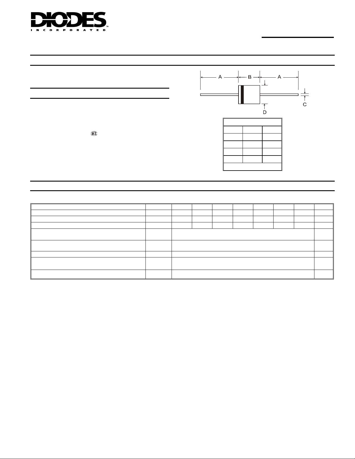
Mechanical Data
• Case: R-6
• Case Material: Molded Plastic. UL Flammability
Classification Rating 94V-0
• Moisture Sensitivity: Level 1 per J-STD-020C
• Terminals: Finish ⎯ Tin. Axial Leads, Solderable per MIL-
STD-202, Method 208
• Polarity: Color Band Indicates Cathode
• Ordering Information: See Page 3
• Approximate Weight: 2.1 grams
6A05 - 6A10
6.0A SILICON RECTIFIER
R-6
Dim Min Max
A 25.40 -
B 8.60 9.10
C 1.20 1.30
D 8.60 9.10
All Dimensions in mm
Maximum Ratings and Electrical Characteristics @T
Ratings at 25°C ambient temperature unless otherwise specified.
Single phase, halfwave, 60Hz, resistive or inductive load.
Characteristic Symbol 6A05 6A1 6A2 6A4 6A6 6A8 6A10 Unit
Maximum Recurrent Peak Reverse Voltage
Maximum RMS Voltage
Maximum DC Blocking Voltage
Maximum Average Forward Rectified Current
9.5mm lead length @ TA = 75°C (See Fig. 1)
Peak Forward Surge Current 8.3 ms single half sinewave superimposed on rated load
Maximum Instantaneous Forward Voltage at 6.0A DC
Maximum DC Reverse Current @ TA = 25°C
at Rated Blocking Voltage @ TA = 100°C
Operating and Storage Temperature Range
Notes: 1. RoHS revision 13.2.2003. Glass and high temperature solder exemptions applied, see EU Directive Annex Notes 5 and 7.
DS28009 Rev. 9 - 2
V
V
V
I
I
V
Tj, T
RRM
RMS
(AV)
FSM
I
RM
DC
FM
STG
50 100 200 400 600 800 1000 V
35 70 140 280 420 560 700 V
50 100 200 400 600 800 1000 V
1 of 3
www.diodes.com
= 25°C unless otherwise specified
A
6.0 A
400 A
0.90 V
10
100
-65 to +175 °C
µA
6A05 - 6A10
© Diodes Incorporated
Page 2
RAGE REC
TIF
CUR
R
T
TANT
O
US FORWARD CUR
RENT
P
O
RWAR
URGE CUR
RENT
R
T
HER
R
T
N
CE J
UNC
TIO
N
6
(A)
5
EN
(A)
IED
O,
IAVE
4
3
A
B
2
1
0
20 40 60 80 100 120 140 160 180
0
TA, AMBIENT TEMPERATURE (ºC)
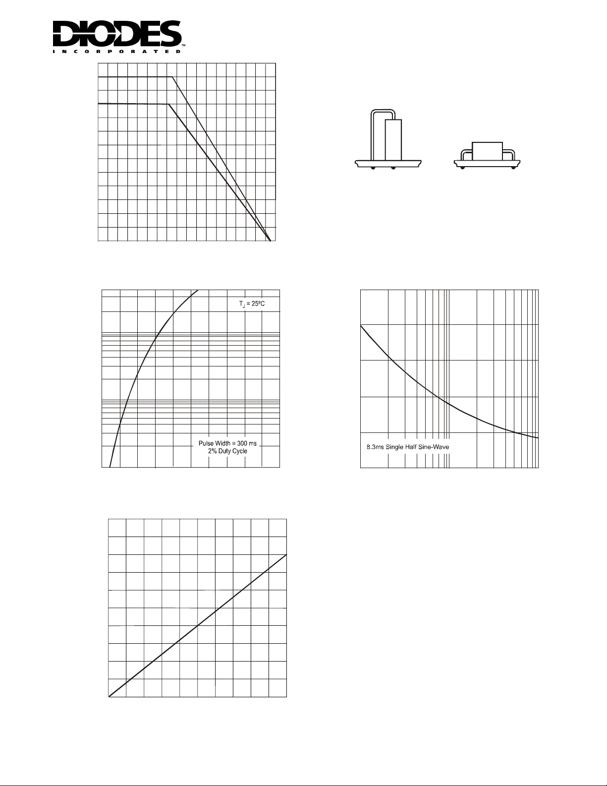
Fig. 1 Output Current Derating Curve
40
10
1.0
Recommended Method
(See Derating "A")
Ground Pl ane: 25mm equivalen t
Standard Method
(See Dera ting "B")
2
copper su rf ace area
Printed Circuit Boa rd Mounting Method
500
(A)
400
300
D S
200
ANE
100
EAK F
F
I , INS
0.1
0.6 0.8 1.0 1.2 1.4
V INSTANTANEOUS FORWARD VOLTAGE (V)
F,
Fig. 2 Typical Forward Characteristics
1.6
FSM,
I
0
110
NUMBER OF CYCLES AT 60 Hz
Fig. 3 Maximum Non-Re petiti v e Peak
Forward Surge Cur r ent
100
25
20
15
A
ESIS
10
MAL
TO AMBIENT (°C/W)
5
JA,
θ
0
0 5 10 2515 20
LEAD LENGTH TO HEAT SINK (mm)
Fig. 4 Typical Thermal Resistance
(Using Standard Mounting Method "B")
DS28009 Rev. 9 - 2
2 of 3
www.diodes.com
6A05 - 6A10
© Diodes Incorporated
Page 3

Ordering Information (Note 2)
Device
6A05-T
6A1-T
6A2-T
6A4-T
6A6-T
6A8-T
6A10-T
Notes: 2. For packaging details, go to our website at http://www.diodes.com/datasheets/ap02008.pdf.
IMPORTANT NOTICE
Diodes Incorporated and its subsidiaries reserve the right to make modifications, enhancements, improvements, corrections or other changes
without further notice to any product herein. Diodes Incorporated does not assume any liability arising out of the application or use of any product
described herein; neither does it convey any license under its patent rights, nor the rights of others. The user of products in such applications shall
assume all risks of such use and will agree to hold Diodes Incorporated and all the companies whose products are represented on our website,
harmless against all damages.
LIFE SUPPORT
Diodes Incorporated products are not authorized for use as critical components in life support devices or systems without the expressed written
approval of the President of Diodes Incorporated.
Packaging Shipping
R-6 500/Tape & Reel, 13-inch
R-6 500/Tape & Reel, 13-inch
R-6 500/Tape & Reel, 13-inch
R-6 500/Tape & Reel, 13-inch
R-6 500/Tape & Reel, 13-inch
R-6 500/Tape & Reel, 13-inch
R-6 500/Tape & Reel, 13-inch
DS28009 Rev. 9 - 2
3 of 3
www.diodes.com
6A05 - 6A10
© Diodes Incorporated
 Loading...