

Page 1
1.5KE6V8(C)A - 1.5KE400(C)A
A A
B
C
D
1500W TRANSIENT VOLTAGE SUPPRESSOR
Features
· 1500W Peak Pulse Power Dissipation
· Voltage Range 6.8V - 400V
· Constructed with Glass Passivated Die
· Uni and Bidirectional Versions Available
· Excellent Clamping Capability
· Fast Response Time
· Lead Free Finish, RoHS Compliant (Note 3)
Mechanical Data
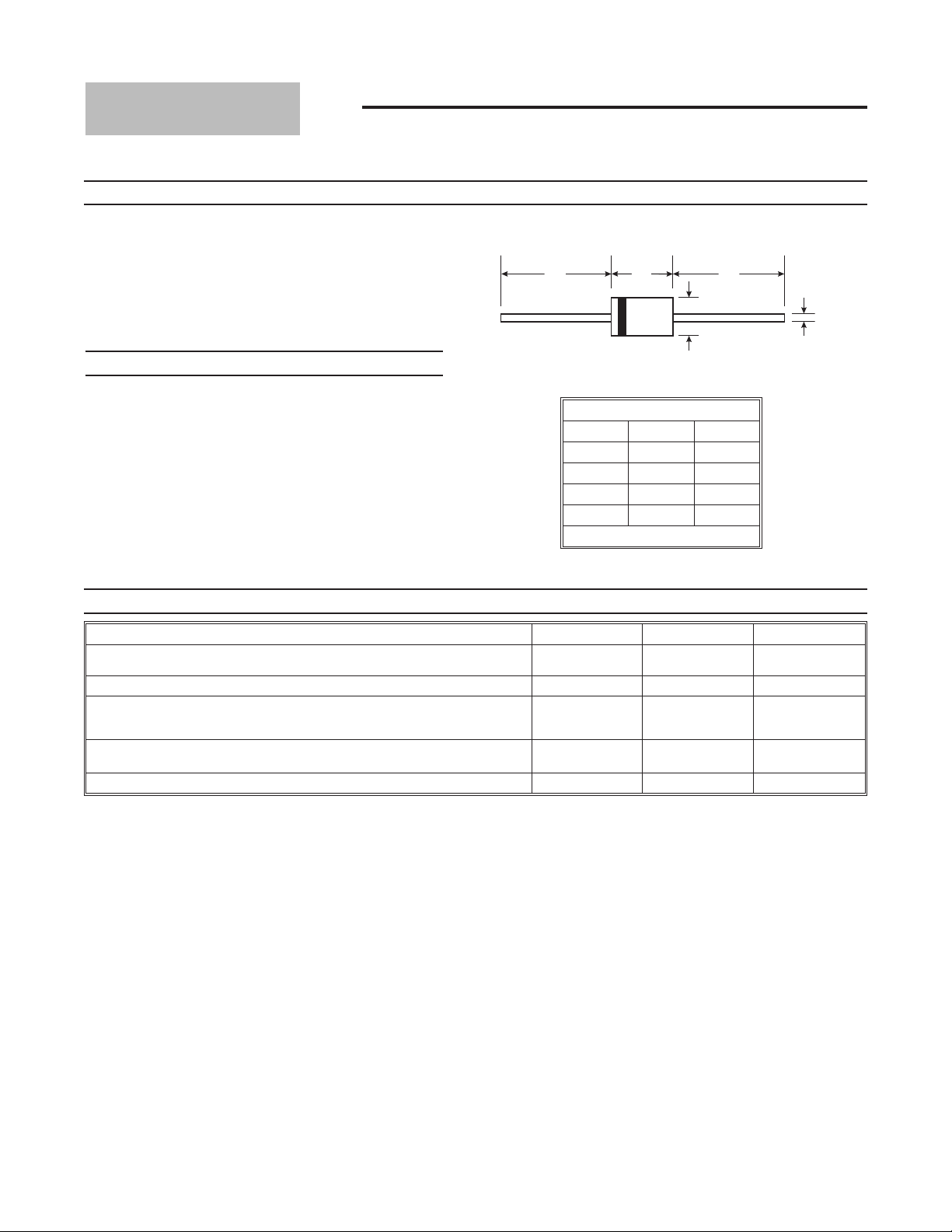
· Case: DO-201
· Case Material: Transfer Molded Epoxy. UL Flammability
Classification Rating 94V-0
· Moisture Sensitivity: Level 1 per J-STD-020C
· Terminals: Finish - Tin. Leads: Axial, Solderable per
MIL-STD-202 Method 208
· Ordering Information: See Page 4
· Marking: Unidirectional - Type Number and Cathode Band
· Marking: Bidirectional - Type Number Only
· Weight: 1.12 grams (approximate)
DO-201
Dim Min Max
A
B
C
D
All Dimensions in mm
25.40 —
8.50 9.53
0.96 1.06
4.80 5.21
Maximum Ratings
Peak Power Dissipation at tp = 1.0ms
(Non-repetitive current pulse, derated above TA = 25°C)
Steady State Power Dissipation at TL = 75°C Lead Lengths 9.5 mm
Peak Forward Surge Current, 8.3 Single Half Sine Wave Superimposed on
Rated Load (8.3ms Single Half Sine Wave,
Duty Cycle = 4 pulses per minute maximum)
Forward Voltage @ IF = 50A 300µs Square Wave Pulse, VBR £ 100V
Unidirectional Only VBR > 100V
Operating and Storage Temperature Range
Notes: 1. Suffix ‘C’ denotes bidirectional device.
2. For bidirectional devices having V
3. RoHS revision 13.2.2003. Glass and high temperature solder exemptions applied, see EU Directive Annex Notes 5 and 7.
@ TA = 25°C unless otherwise specified
Characteristic Symbol Value Unit
of 10 volts and under, the IR limit is doubled.
R
I
Tj, T
P
P
FSM
V
pk
d
F
STG
1500 W
5.0 W
200 A
3.5
5.0
-55 to +175 °C
V
DS21503 Rev. 11 - 2 1 of 4 1.5KE6V8(C)A - 1.5KE400(C)A
www.diodes.com ã Diodes Incorporated
Page 2
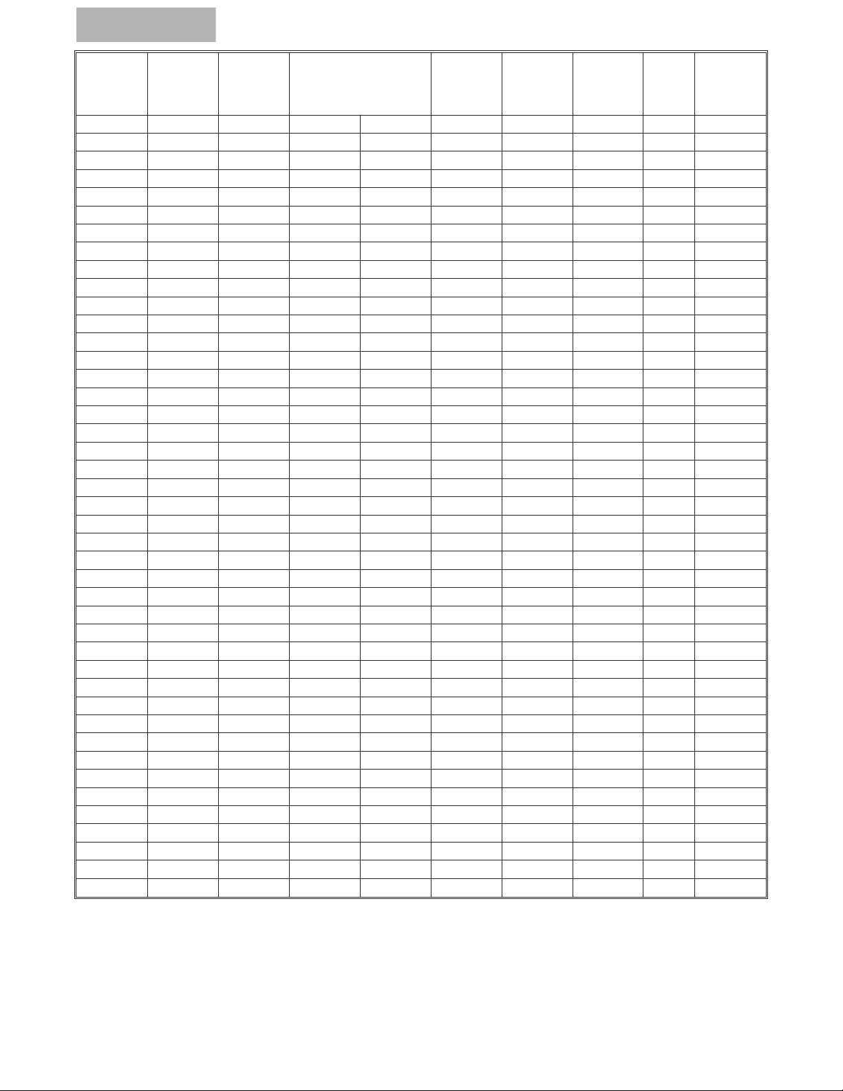
Type
Number
(Note 1)
Number
(Note 1)
(UNI) (BI)
Type
Reverse
Standoff
Voltage
V
(V)
RWM
Breakdown Voltage
VBR @ I
T
Min (V) Max (V)
Test
Current
Max.
Reverse
Leakage
(Note 2)
@ V
R
Max.
Clamping
Voltage
@ I
pp
Max.
Peak
Pulse
Current
It (mA) IR (mA) VC (V) IPP (A)
Max.
Voltage
Temp.
Variation
of V
%/°C
1.5KE6V8A 1.5KE6V8CA 5.80 6.45 7.14 10 1000 10.5 143.0 0.057
1.5KE7V5A 1.5KE7V5CA 6.40 7.13 7.88 10 500 11.3 132.0 0.061
1.5KE8V2A 1.5KE8V2CA 7.02 7.79 8.61 10 200 12.1 124.0 0.065
1.5KE9V1A 1.5KE9V1CA 7.78 8.65 9.55 1.0 50 13.4 112.0 0.068
1.5KE10A 1.5KE10CA 8.55 9.50 10.50 1.0 10 14.5 103.0 0.073
1.5KE11A 1.5KE11CA 9.40 10.50 11.60 1.0 5.0 15.6 96.0 0.075
1.5KE12A 1.5KE12CA 10.20 11.40 12.60 1.0 5.0 16.7 90.0 0.078
1.5KE13A 1.5KE13CA 11.10 12.40 13.70 1.0 5.0 18.2 82.0 0.081
1.5KE15A 1.5KE15CA 12.80 14.30 15.80 1.0 5.0 21.2 71.0 0.084
1.5KE16A 1.5KE16CA 13.60 15.20 16.80 1.0 5.0 22.5 67.0 0.086
1.5KE18A 1.5KE18CA 15.30 17.10 18.90 1.0 5.0 25.2 59.5 0.088
1.5KE20A 1.5KE20CA 17.10 19.00 21.00 1.0 5.0 27.7 54.0 0.090
1.5KE22A 1.5KE22CA 18.80 20.90 23.10 1.0 5.0 30.6 49.0 0.092
1.5KE24A 1.5KE24CA 20.50 22.80 25.20 1.0 5.0 33.2 45.0 0.094
1.5KE27A 1.5KE27CA 23.10 25.70 28.40 1.0 5.0 37.5 40.0 0.096
1.5KE30A 1.5KE30CA 25.60 28.50 31.50 1.0 5.0 41.4 36.0 0.097
1.5KE33A 1.5KE33CA 28.20 31.40 34.70 1.0 5.0 45.7 33.0 0.098
1.5KE36A 1.5KE36CA 30.80 34.20 37.80 1.0 5.0 49.9 30.0 0.099
1.5KE39A 1.5KE39CA 33.30 37.10 41.00 1.0 5.0 53.9 28.0 0.100
1.5KE43A 1.5KE43CA 36.80 40.90 45.20 1.0 5.0 59.3 25.3 0.101
1.5KE47A 1.5KE47CA 40.20 44.70 49.40 1.0 5.0 64.8 23.2 0.101
1.5KE51A 1.5KE51CA 43.60 48.50 53.60 1.0 5.0 70.1 21.4 0.102
1.5KE56A 1.5KE56CA 47.80 53.20 58.80 1.0 5.0 77.0 19.5 0.103
1.5KE62A 1.5KE62CA 53.00 58.90 65.10 1.0 5.0 85.0 17.7 0.104
1.5KE68A 1.5KE68CA 58.10 64.60 71.40 1.0 5.0 92.0 16.3 0.104
1.5KE75A 1.5KE75CA 64.10 71.30 78.80 1.0 5.0 103.0 14.6 0.105
1.5KE82A 1.5KE82CA 70.10 77.90 86.10 1.0 5.0 113.0 13.3 0.105
1.5KE91A 1.5KE91CA 77.80 86.50 95.50 1.0 5.0 125.0 12.0 0.106
1.5KE100A 1.5KE100CA 85.50 95.00 105.00 1.0 5.0 137.0 11.0 0.106
1.5KE110A 1.5KE110CA 94.00 105.00 116.00 1.0 5.0 152.0 9.9 0.107
1.5KE120A 1.5KE120CA 102.00 114.00 126.00 1.0 5.0 165.0 9.1 0.107
1.5KE130A 1.5KE130CA 111.00 124.00 137.00 1.0 5.0 179.0 8.4 0.107
1.5KE150A 1.5KE150CA 128.00 143.00 158.00 1.0 5.0 207.0 7.2 0.108
1.5KE160A 1.5KE160CA 136.00 152.00 168.00 1.0 5.0 219.0 6.8 0.108
1.5KE170A 1.5KE170CA 145.00 162.00 179.00 1.0 5.0 234.0 6.4 0.108
1.5KE180A 1.5KE180CA 154.00 171.00 189.00 1.0 5.0 246.0 6.1 0.108
1.5KE200A 1.5KE200CA 171.00 190.00 210.00 1.0 5.0 274.0 5.5 0.108
1.5KE220A 1.5KE220CA 185.00 209.00 231.00 1.0 5.0 328.0 4.6 0.108
1.5KE250A 1.5KE250CA 214.00 237.00 263.00 1.0 5.0 344.0 5.0 0.110
1.5KE300A 1.5KE300CA 256.00 285.00 315.00 1.0 5.0 414.0 5.0 0.110
1.5KE350A 1.5KE350CA 300.00 332.00 368.00 1.0 5.0 482.0 4.0 0.110
1.5KE400A 1.5KE400CA 342.00 380.00 420.00 1.0 5.0 548.0 4.0 0.110
BR
Notes: 1. Suffix ‘C’ denotes bidirectional device.
2. For bidirectional devices having V
of 10 volts and under, the IR limit is doubled.
R
DS21503 Rev. 11 - 2 2 of 4 1.5KE6V8(C)A - 1.5KE400(C)A
www.diodes.com
Page 3

1.0
10
100
0.1 1.0 10 100 1000 10,000
P , PEAK PULSE POWER (kW)
P
T = 25ºC
C
IMPULSE
SINE WAVE
SQ. WAVE
10 X 1000 Waveform
as defined by REA
0 25 50 75 100 125 150 175 200
100
75
50
25
0
T , AMBIENT TEMPERATURE (°C)
A
Fig. 4 Pulse Derating Curve
PEAK PULSE DERATING (% PEAK PWR OR CURRENT)
L = 9.5 mm
0
25 50 75 100 125 150 175
200
0
1.25
2.5
3.75
5.0
T , LEAD TEMPERATURE (°C)
L
Fig. 5 Steady State Power Derating
P , STEADY STATE POWER DISSIPATION (W)
d
Single Phase
Half-Wave 60Hz
Resistive or
Inductive Load
0 1 2
3
100
50
0
I , PEAK PULSE CURRENT (%I )
Ppp
Peak Value I
pp
Half Value I /2
pp
10 X 1000 Waveform
as defined by R.E.A.
t
p
t, TIME (ms)
Fig. 1 Pulse Waveform
1 10 100 1000
10
100
1000
10,000
V , REVERSE STANDOFF VOLTAGE (V)
RWM
Fig. 2 Typical Total Capacitance
C , CAPACITANCE (pF)
T
Measured at
Stand-off Voltage
Measured at
Zero Bias
DS21503 Rev. 11 - 2 3 of 4 1.5KE6V8(C)A - 1.5KE400(C)A
www.diodes.com
Page 4

Ordering Information
IMPORTANT NOTICE
Diodes Incorporated and its subsidiaries reserve the right to make modifications, enhancements, improvements, corrections or other changes without further
notice to any product herein. Diodes Incorporated does not assume any liability arising out of the application or use of any product described herein; neither
does it convey any license under its patent rights, nor the rights of others. The user of products in such applications shall assume all risks of such use and will
agree to hold Diodes Incorporated and all the companies whose products are represented on our website, harmless against all damages.
LIFE SUPPORT
Diodes Incorporated products are not authorized for use as critical components in life support devices or systems without the expressed written approval of the
President of Diodes Incorporated.
(Note 4 & 5)
Device
(Type Number)-B*
(Type Number)-T*
Packaging Shipping
DO-201 1K/Bulk
DO-201 1K/Tape & Reel, 13-inch
Notes: 4. *Add "-B" or "-T" to the appropriate type number in Table 1. Example: 6.40 Reverse Standoff Voltage, UNI = 1.5KE7V5A-B.
5. For packaging details, visit our website at http://www.diodes.com/datasheets/ap02008.pdf.
DS21503 Rev. 11 - 2 4 of 4 1.5KE6V8(C)A - 1.5KE400(C)A
www.diodes.com
 Loading...