

Diode LED Lutron Hi-Lume L3D User Manual [en, es, fr]
L3D 3-Wire and EcoSystemR
ULR Listed Driver |
L3DA4U1UKL-AV120 (12 V)
L3DA4U1UKL-CV240 (24 V)
L3DA4U1UKL-XXXXX
120 – 277 V~ 50 / 60 Hz ULR Listed Driver
Important Notes: Please read before installing.
• For installation by a qualified electrician in accordance with all local and
national electrical codes.
• Use copper conductors only.
• For indoor use only.
• For 277 V~ applications, a suitable barrier should be installed between
the input and Class 2 wiring per local and national electrical wiring codes.
• Check to see that the driver type and rating are suitable for the
application.
• DO NOT install if product has any visible damage.
• If moisture or condensation is evident, allow the product to dry completely
before installation.
• Operate between 32 °F (0 °C) and 104 °F (40 °C).
• 0% to 90% humidity, non-condensing.
Installation
041436
Rev. A
01/2014
English
Required Components
One Compatible Lutron Control
1
See list of compatible controls on reverse side.
2
Please refer to Installation Sheet with your control
for wiring instructions.
1, 2
Need Help? www.lutron.com/hilumeled or call the Lutron LED Center of Excellence at 1.877.346.5338
For each system ensure you have:
3
At least one ULR Listed Hi-LumeR A-Series L3D Driver
+ +
3
Driver output range is factory-set.
Different output ratings are available for different loads.
At least one compatible LED Load (light engine)
4
5 W minimum.
5
Load ratings must match driver output ratings.
4, 5
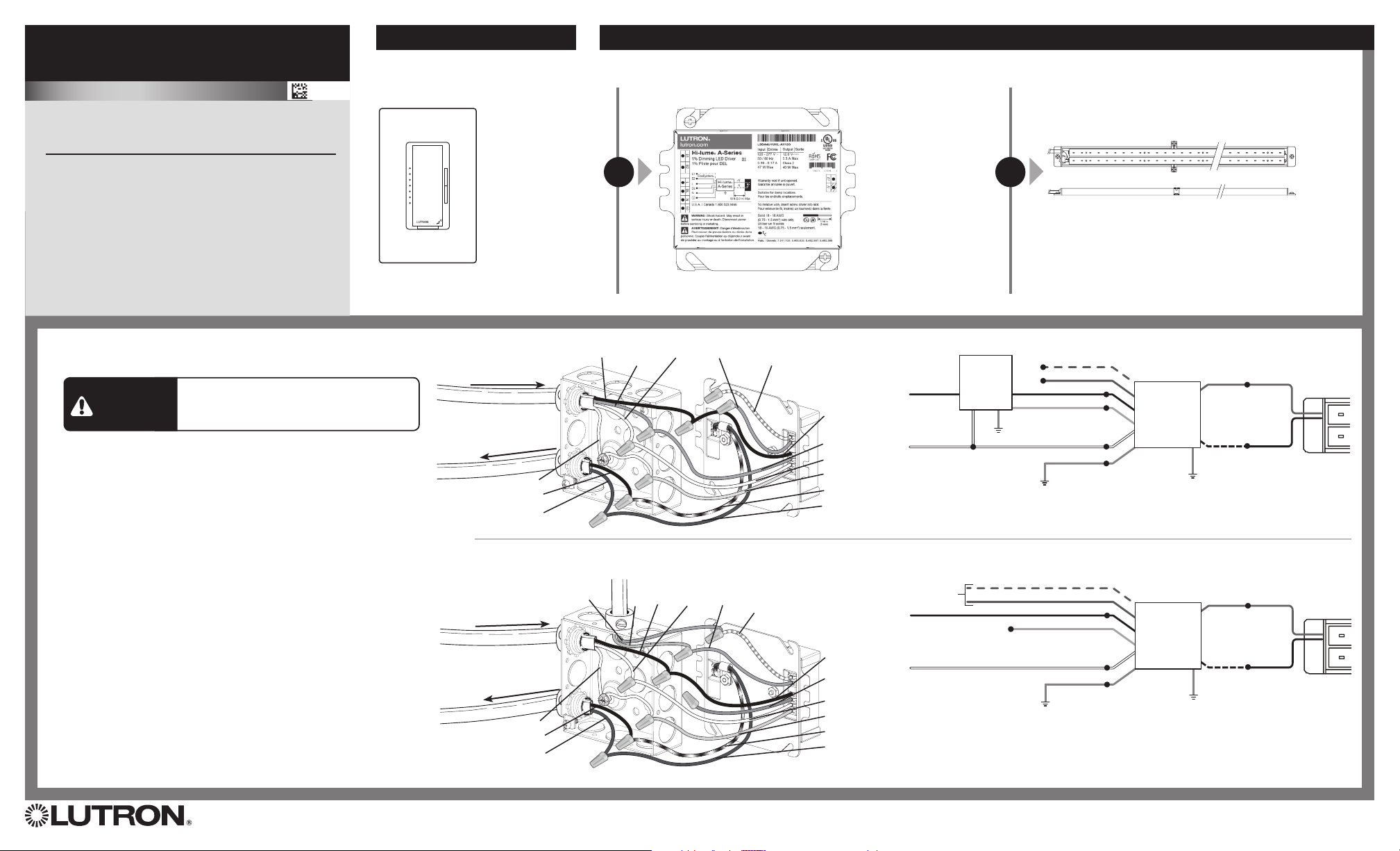
Install the ULR Listed Driver
3-Wire Controls
Switched
Hot
Dimmed
Hot
Neutral
Purple
Purple with
White Stripe
From Line / Control
Shock Hazard. May result in serious injury
WARNING
or death. Turn off power at circuit breaker
before installing the unit.
When installing the ULR Listed Driver,
wire as shown.
1. Remove driver and mounting plate from the rest of the junction box.
Do not remove driver from mounting plate.
2. Using leads and ground (bundled in junction box) make power, load,
and ground connections with provided wire nuts
(see wiring diagrams). Cap off any unused wires.
3. Re-install LED driver and mounting plate to the junction box.
4. Ensure compatible dimmer and load are installed and restore power
to circuit. See reverse side for Compatible Controls.
6
Driver and junction box must be grounded in accordance with local and national electrical codes. Ground provided by grounding of junction box and by using the green ground wire connection.
120 V~ / 277 V~ 50/60 Hz
To LED
Load
Bare
- LED
+ LED
OR
EcoSystemR Controls
E1
From Line
120 V~ / 277 V~ 50/60 Hz
To LED
Load
Bare
- LED
+ LED
From EcoSystemR Control
E2
Neutral
PurpleHot
Purple with
White Stripe
Switched Hot
(Black)
Dimmed Hot
(Orange)
Neutral (White)
Ground (Green)
- V (Black with White Stripe)
+ V (Red)
Switched Hot
(Black)
Dimmed Hot
(Orange)
Neutral (White)
Ground (Green)
- V (Black with White Stripe)
+ V (Red)
3-Wire Wiring Diagram
E1 (Purple / W hite)
E2 (Purple)
Switched Hot (Black)
Dimmed Hot (Orange)
5
Ground
Neutral (White)
Ground (Green)
Hot
Neutral
Neutral
(White)
LutronR
3-Wire
Forward
Phase
Dimmer
EcoSystemR Wiring Diagram
To
EcoSystemR
Digital Link
E1 (Purple / W hite)
E2 (Purple)
Hot (Black)
Dimmed Hot (Orange)
Neutral (White)
Ground (Green)
A-Series LED
6
A-Series LED
6
ULR Listed
Hi-lumeR
Dimming
Driver
Ground
ULR Listed
Hi-lumeR
Dimming
Driver
Ground
+ V (Red)
- V
(Black with
white stripe)
6
+ V (Red)
- V
(Black with
white stripe)
6
+ LED
- LED
+ LED
- LED
LED Light
Engine
LED Light
Engine
Lutron Electronics Co., Inc. | 7200 Suter Road
Coopersburg PA, 18036-1299
L3D 3-Wire and EcoSystemR
ULR Listed Driver
Compatible Controls
Compatible Controls
• 3-Wire Controls
• EcoSystem
Please consult individual component installation for
more details.
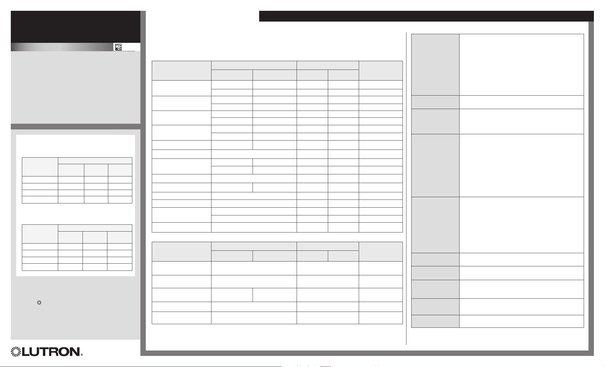
Driver Leads
Maximum driver-to-LED light engine wire length for
Constant Current Drivers:
Wire Gauge
18 AWG (0.75 mm2) 30 ft (9 m) 15 ft (4.5 m) 10 ft (3 m)
16 AWG (1.5 mm
14 AWG (2.5 mm2) 50 f t (15 m) 40 ft (12 m) 25 ft (7.5 m)
12 AWG (4.0 mm2) 100 ft (30 m) 60 ft (18 m) 40 ft (12 m)
Maximum driver-to-LED light engine wire length for
Constant Voltage Drivers:
Wire Gauge
18 AWG (0.75 mm2) 10 ft (3 m) 15 ft (4.5 m) 30 ft (9 m)
16 AWG (1.5 mm2) 15 ft (4.5 m) 25 ft (7.5 m) 50 ft (15 m)
14 AWG (2.5 mm2) 25 ft (7.5 m) 40 f t (12 m) 75 ft (22.5 m)
12 AWG (4.0 mm2) 40 ft (12 m) 60 ft (18 m) 100 f t (30 m)
Warranty:
For warranty information, please visit:
www.lutron.com/BallastDriverWarranty
Lutron, , Hi-lume, Nova T*, Nova, Ariadni, Verti,
Lyneo, PowPak, EcoSystem, HomeWorks, GRAFIK
Eye, Skylark, Diva, Maestro, Maestro Wireless,
Quantum, and RadioRA, are registered trademarks
and RadioRA 2 and Energi Savr Node are trademarks
of Lutron Electronics Co. Inc.
©2013 Lutron Electronics Co., Inc.
R Controls
Maximum Lead Length
200 mA to
700 mA
2
) 35 ft (10.5 m) 25 ft (7.5 m) 15 ft (4.5 m)
10 V- to
20 V-
710 mA to
1.50 A
Maximum Lead Length
20.5 V- to
40 V-
Lutron Electronics Co., Inc.
7200 Suter Road
Coopersburg PA, 18036-1299
1.51 A to
2.10 A
40.5 V- to
60 V-
041436
Rev. A
01/2014
Need Help? www.lutron.com/hilumeled or call the Lutron LED Center of Excellence at 1.877.346.5338
Compatible Controls
For assistance selecting controls, contact our LED Center of Excellence at 1.877.346.5338 or
LEDs@lutron.com
3-Wire Controls
Product Part Number Drivers per Control 7Measured
120 V~ 277 V~ 120 V~ 277 V~
Nova T*R
R
Nova
Skylark
R
R
Diva
Ariadni
R
Vierti
R
R
Maestro
Maestro Wireless
R Lx
Lyneo
RadioRA
R
R 2
HomeWorksR QS
Interfaces
8
GP Dimming Panels Various 1 – 41 1 – 88 100% – 1%
NTF-10- NTF-10-277- 1 – 41 1 – 44 100% – 1%
NTF-103P- NTF-103P-277- 1 – 20 1 – 33 100% – 1%
NF-10- NF-10-277- 1 – 41 1 – 44 100% – 1%
NF-103P- NF-103P-277- 1 – 20 1 – 33 100% – 1%
SF-10P- SF-12P-277- 1 – 20 1 – 33 100% – 1%
SF-103P- SF-12P-277-3 1 – 20 1 – 33 100% – 1%
DVF-103P- DVF-103P-277- 1 – 20 1 – 33 100% – 1%
DVSCF-103P- DVSCF-103P-277- 1 – 20 1 – 33 100% – 1%
AYF-103P- AYF-103P-277- 1 – 20 1 – 44 100% – 1%
VTF-6A- 1 – 15 1 – 33 100% – 1%
MAF-6AM- MAF-6AM-277- 1 – 15 1 – 20 100% – 1%
MSCF-6AM- MSCF-6AM-277- 1 – 15 1 – 20 100% – 1%
MRF2-F6AN-DV- 1 – 15 1 – 33 100% – 1%
LXF-103PL- LXF-103PL-277- 1 – 20 1 – 33 100% – 1%
RRD-F6AN-DV- 1 – 15 1 – 33 100% – 1%
HQRD-F6AN-DV 1 – 15 1 – 33 100% – 1%
PHPM-3F-120 1 – 41 – 100% – 1%
PHPM-3F-DV 1 – 41 1 – 88 100% – 1%
EcoSystemR Controls
Product
PowPakR dimming Module
with EcoSystemR
Energi Savr NodeT with
EcoSystem
GRAFIK Eye
EcoSystemR
Quantum
HomeWorks
EcoSystemR
7
No derating required in multigang applications provided that driver count does not exceed quantity listed.
8
For use with 3-wire controls in Commercial Systems, RadioRAR Systems, HomeWorksR or Home Systems applications.
Note: For information about Legacy product use in existing control application, contact LEDs@lutron.com
R
R QS with
R
R QS with
120 V~ 277 V~ 120 V~ 277 V~
RMJ-ECO32-DV-B
QSN-1ECO-S, QSN-2ECO-S
QSGRJ-_E,
QSGR-_E
Various
QSGRJ-_E, QSGR-_E, LQSE-2ECO-D
Part Number Drivers per Control Measured
32 per EcoSystem
64 per EcoSystem
64 per EcoSystem
64 per EcoSystem
64 per EcoSystem
R link
R link
R link
R link
R link
Light
Output Range
Light
Output Range
100% – 1%
100% – 1%
100% – 1%
100% – 1%
100% – 1%
L3D Troubleshooting
• Verify that the system is wired correctly according to wiring
diagram.
• Verify that the LED load is wired correctly; red to positive,
black/white to negative.
LED does not
illuminate
LED does not dim
LED exhibits a flash
or steppy dimming
on first use
LED is flashing,
flickering,
dropping out, or
has poor dimming
performance
LED is flashing slowly
(6 to 8 second
interval)
LED is dimming in
reverse
LED output appears
dim at high-end
LED emits audible
noise at dimmed
levels
LED strip / array has
dark spots
Not all LED strips /
fixtures illuminate
9
Certain constant current loads may have additional circuitry and certain constant voltage loads may have
added capacitance. Contact the Lutron LED Center of Excellence at 1.877.346.5338 for more information
about these loads.
• Verify that the LED load is compatible with the specified
voltage output of the driver.
• If using a constant voltage driver, verify that the LED load is for
“constant voltage” applications.
• If using a constant current driver, verify that the LED load is for
“constant current” applications.
• Lutron drivers are not for use with MR16 LED lamps.
• Verify that Switched Hot and Dimmed Hot are connected to
the proper terminals.
• Drivers will “learn” the LED load on first startup. This is a
one-time event for a particular driver/LED combination.
Running the load at full output for 5 seconds should complete
“learning.”
• Verify that a compatible dimmer is being used to control the
driver.
• Verify that Switched Hot and Dimmed Hot are connected to
the proper terminals.
• If using a constant voltage driver, verify that the LED load is for
“constant voltage” applications.
• Verify that length of wires between driver and LED does not
exceed Lutron specification.
• Certain types of LED loads may be incompatible.
• Verify that the rated voltage is present at the driver.
• Lutron drivers are not for use with MR16 LED lamps.
• If using a constant voltage driver, verify that your LED load
does not exceed the maximum specified power rating of the
driver (40 W).
• If using a constant voltage driver, verify that your LED load
matches the specified voltage output of the driver.
• If using a constant current driver, verify that your LED load falls
within the specified voltage rating of the driver.
• Verify that length of wire between driver and LED does not
exceed Lutron specification.
• Certain types of LED loads may be incompatible.
• Verify that Switched Hot and Dimmed Hot are connected to
the proper terminals.
• Verify that the driver is operating in an environment within its
ambient temperature rating.
• Certain types of LED loads may be incompatible.
• If using a constant current driver, check to see if dimming
parallel-wired LEDs with CCR driver; PWM is recommended
for these applications.
• Verify that multiple LEDs connected to a single driver are
properly wired.
9
9
9
 Loading...