

DINUY S.A. c/Auzolan 2, 20303 Irun (Spain)
Tel.: +34943627988 – E-mail: knx@dinuy.com – Web: www.dinuy.com
CAPACITIVE TOUCH THERMOSTAT
TM KNT 001 TM KNT 002
USER MANUAL
DINUY S.A. c/Auzolan 2, 20303 Irun (Spain)
Tel.: +34943627988 – E-mail: knx@dinuy.com – Web: www.dinuy.com 2
INTRODUCTION
- The new DINUY Touch Temperature Controllers are built on a functional evolution of the Laüka Capacitive Switches.
- Two different references are available:
· TM KNT 001: with button for setting the Fan-Coil Speed.
· TM KNT 002: with button for setting the HVAC Special Mode.
- Incorporates a Display which shows the Set-point Temperature or the measured one, as well as the Relative Humidity.
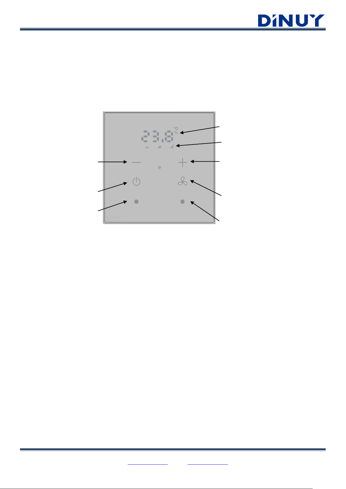
- It has 4 keys with preset functionality:
- Among their keys, there are 2 freely configurable buttons, which can be configured as Switch, Dimmer, Control of Blind /
Shutter, Scenes, etc.
- Incorporate Temperature, Luminosity and Humidity sensors.
- Its main functionality is complemented by 4 Binary / Analog Inputs, which can be connected to a Door / Window Sensor or
a DINUY Temperature Probe.
- Allows enabling and configuring one Heating and / or Cooling Thermostat.
- The 2 free-configuration buttons incorporate 2 configurable RGB LEDs.
- They do not need external supply, only the KNX Bus.
- Device designed for flush mounting into universal switch boxes.
- Programming and commissioning via ETS5 or later version.
Free-configuration key 1
On/Off Thermostat.
A long press >2sec changes the value of the
Display Temperature ↔ Humidity
Decrease Temperature set-point.
When pressed, the Setpoint Temperature
will be displayed flashing
Display
Fan Speed or HVAC Special Mode indicator
Increase Temperature set-point.
When pressed, the Setpoint Temperature
will be displayed flashing
TM KNT 001: Fan Speed
A long press >2sec sets the Speed to Auto (the 3
LEDs turn on and off)
TM KNT 002: HVAC Special Mode
Consecutive presses will change the HVAC mode:
Auto → Comfort → StandBy → Eco → Auto
Free-configuration key 2

DINUY S.A. c/Auzolan 2, 20303 Irun (Spain)
Tel.: +34943627988 – E-mail: knx@dinuy.com – Web: www.dinuy.com 3
- Technical specifications:
KNX
Supply voltage
21 ~ 32VDC
Bus current
< 4mA
Type of connection
KNX Bus terminal
Programming by
ETS5 or later
KNX Topology
TP1
Commissioning
System-Mode
Inputs
Number of Inputs
4 Inputs for Door Contact or Temperature Probe
Type
Binaries or Analogs
Compatible Temperature Probes
ST KNT 001 and ST KNT 002
Temperature Probe Range
-40ºC bis +100ºC
Maximum length of the cable
<10m
Sensors
Temperature
-40ºC bis +125ºC // Accuracy: ±0,4ºC (-10ºC bis +85ºC)
Luminosity
0,045Lux bis 188.000Lux
Relative Humidity
0% bis 100% // Accuracy: ±4% (0% bis 80%)
Display
From 0.0 to 99.9
Dimensions
90 x 90 x 14mm
Working Temperature
-5ºC bis +45ºC
Storage Temperature
-30ºC bis +70ºC
Degree of protection
IP20 (EN60529)
Directives
Security 73/23/EEC
EMC 204/108/EC
Standards
KNX Standard 2.0
EN60669-1, 2-1 & 2-3
DINUY S.A. c/Auzolan 2, 20303 Irun (Spain)
Tel.: +34943627988 – E-mail: knx@dinuy.com – Web: www.dinuy.com 4
CONFIGURATION
Device Configuration
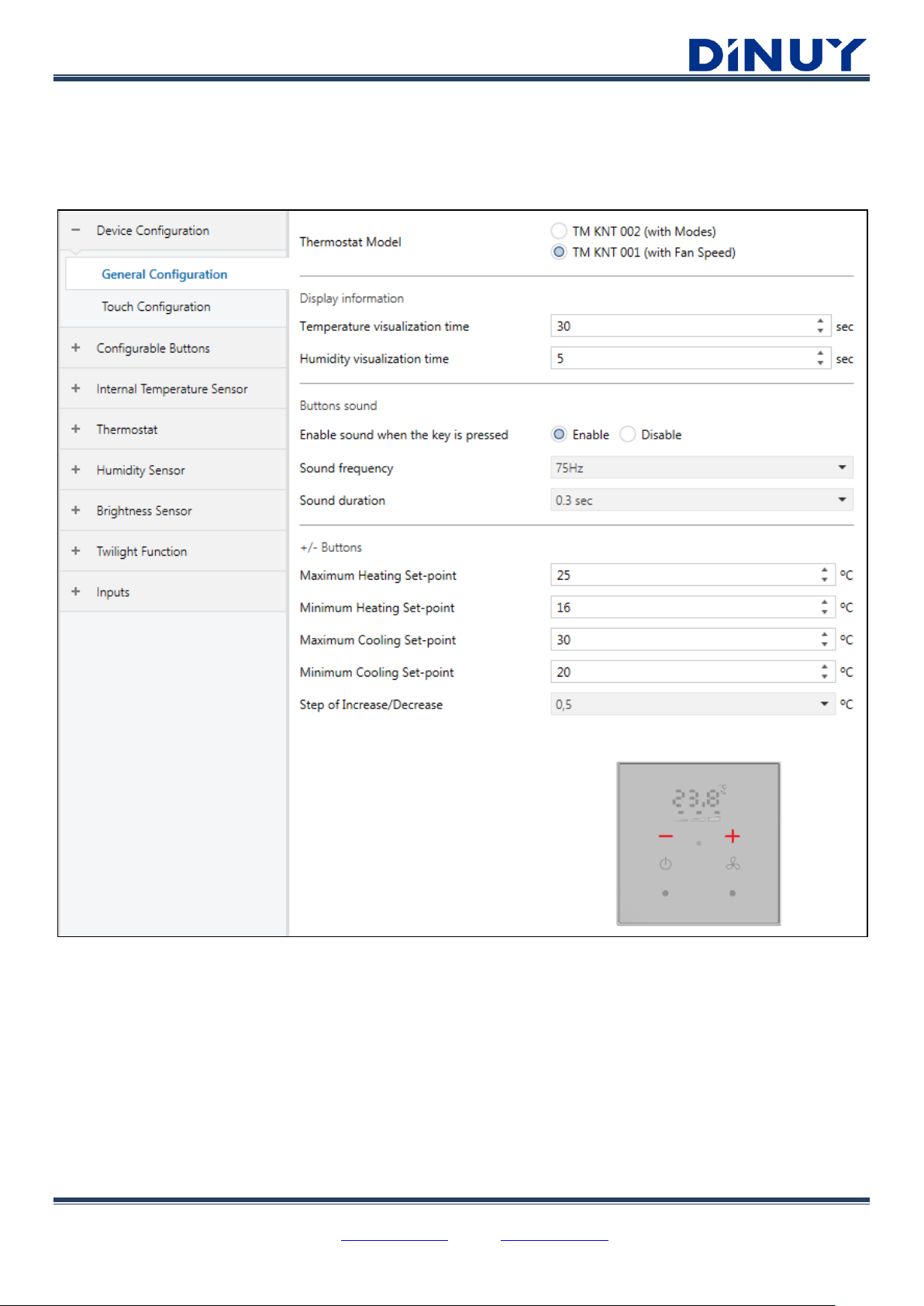
An initial window is available where some main parameters can be set:
General Configuration:
· Thermostat Model:
▪ TM KNT 001: with button for setting the Fan-Coil Speed.
▪ TM KNT 002: with button for setting the HVAC Special Mode.
DINUY S.A. c/Auzolan 2, 20303 Irun (Spain)
Tel.: +34943627988 – E-mail: knx@dinuy.com – Web: www.dinuy.com 5
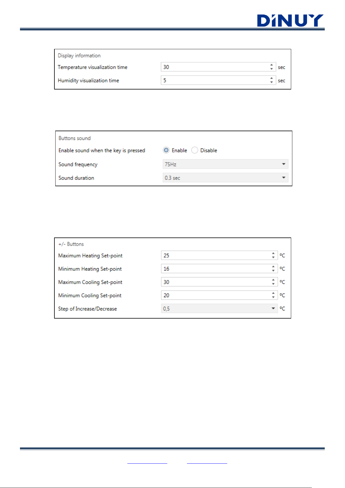
· Display information:
· Temperature visualization time: Time during which the temperature of the room will be displayed.
· Humidity visualization time: Time during which the humidity of the room will be displayed.
· Buttons sound:
· Enable sound when the key is pressed: An acoustic signal when any of the keys is pressed can be enabled.
· Sound frequency: The higher the frequency, the higher the buzzing.
· Sound duration: Sets the duration of the buzzing.
· +/- Buttons:
· Maximum Heating Set-point: Sets the maximum temperature setpoint for the Heating mode.
· Minimum Heating Set-point: Sets the minimum temperature setpoint for the Heating mode.
· Maximum Cooling Set-point: Sets the maximum temperature setpoint for the Cooling mode.
· Minimum Cooling Set-point: Sets the minimum temperature setpoint for the Cooling mode.
· Step of Increase/Decrease: Change in the setpoint each time the temperature setpoint keys are pressed.
DINUY S.A. c/Auzolan 2, 20303 Irun (Spain)
Tel.: +34943627988 – E-mail: knx@dinuy.com – Web: www.dinuy.com 6
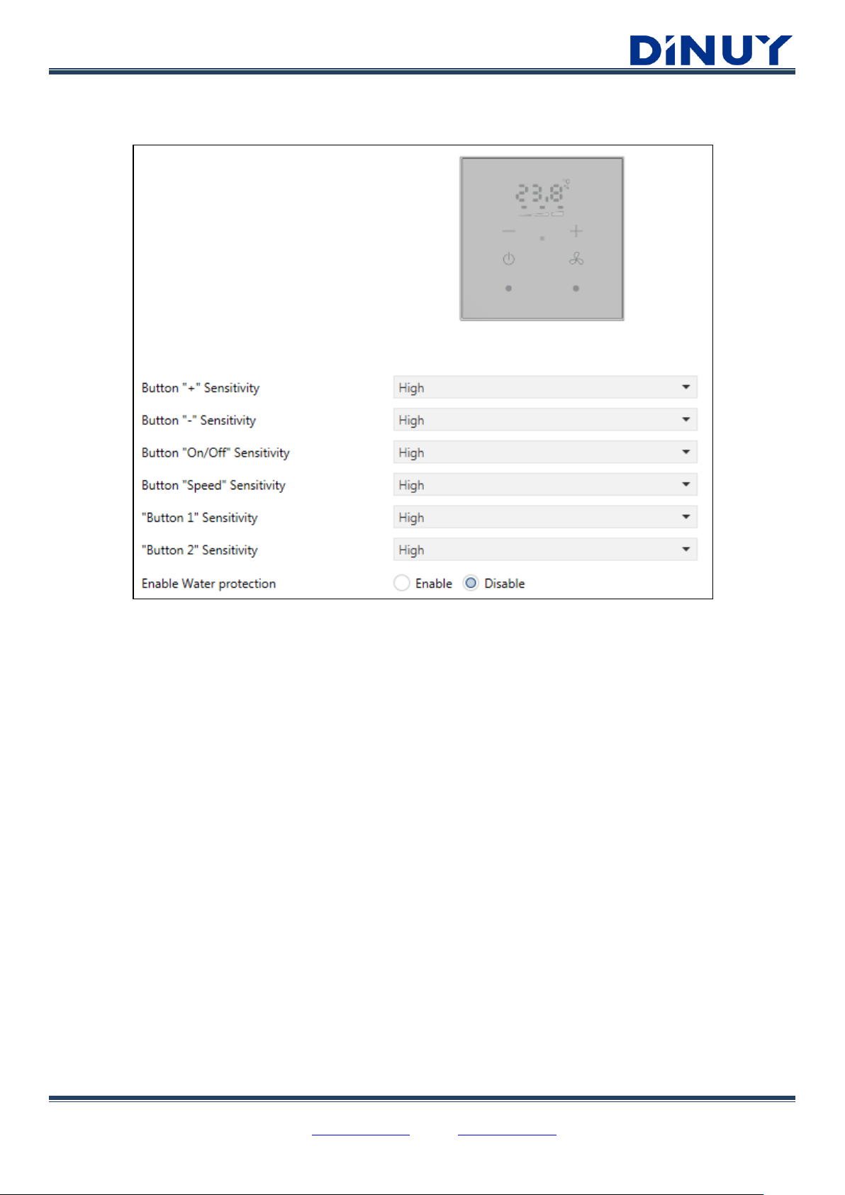
Touch Configuration:
· Sensitivity: Determines the sensitivity of each key.
· Enable Water protection: The operation of the keys can be automatically disabled if some water is detected
on the surface of the button. If this function is disabled, the pushbutton may work incorrectly when, for example,
is trying to operate with wet hands.

DINUY S.A. c/Auzolan 2, 20303 Irun (Spain)
Tel.: +34943627988 – E-mail: knx@dinuy.com – Web: www.dinuy.com 7
Configurable Buttons - Configuration
The Thermostat has 2 freely configurable keys, with their corresponding RGB LEDs:
· Function of Channel:
DINUY S.A. c/Auzolan 2, 20303 Irun (Spain)
Tel.: +34943627988 – E-mail: knx@dinuy.com – Web: www.dinuy.com 8
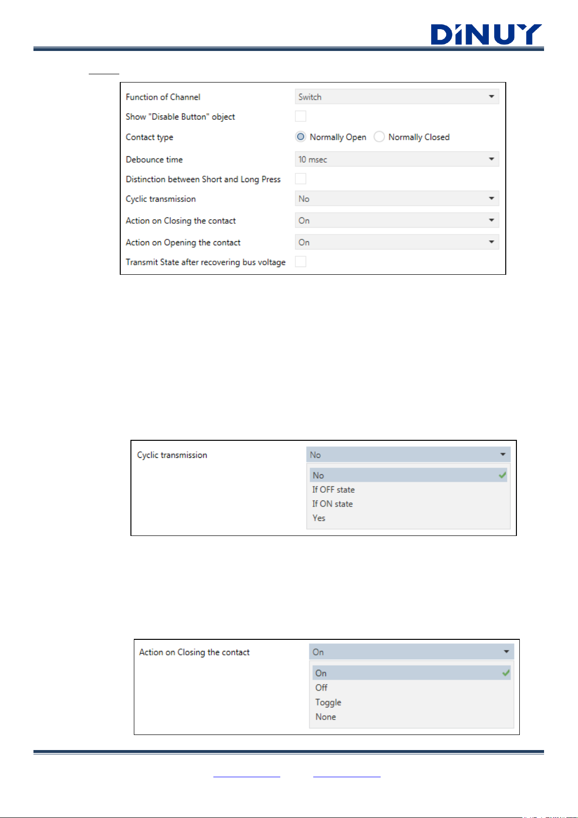
· Switch:
· Show “Disable Button” object: Allows activating/deactivating the key through the object "[PB] Disable
Button". Writing a "0" in this object, the key will be enabled, while if a "1" is written the key will be disabled
and will not send telegrams to the bus.
· Contact type: Sets if it is a Normally Open or Normally Closed contact.
· Debounce time: Parameter to adjust the bounce suppression time when there is a switch. Prevents
multiple unwanted actions, caused by the rebound when a contact is closed.
· Distinction between Short and Long Press: Allows distinguishing between a short and a long press. In
this way, it is possible to trigger 2 different actions depending on the length of the action.
- If there is no distinction between Short and Long press:
· Cyclic transmission: Sets the cyclical sending of the object “[PB] Press”.
· No: It will not be updated cyclically, but state transmission can be enabled after recovering bus voltage.
· If OFF state: The object “[PB] Press” will be cyclically sent if its value is “0”.
· If ON state: The object “[PB] Press” will be cyclically sent if its value is “1”.
· Yes: The object “[PB] Press” will be cyclically sent if its value is “0” or “1”.
· Action on Closing the contact: Action to be carried out when the key is pressed.
DINUY S.A. c/Auzolan 2, 20303 Irun (Spain)
Tel.: +34943627988 – E-mail: knx@dinuy.com – Web: www.dinuy.com 9
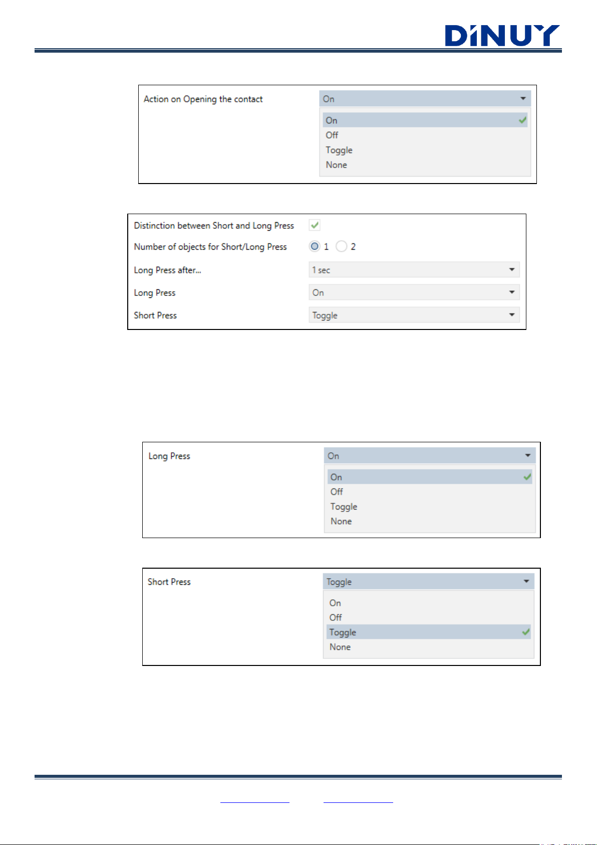
· Action on Opening the contact: Action to be carried out when the key is released.
- If there is distinction between Short and Long press:
· Number of objects for Short/Long Press:
· 1 object: “[PB] Press” → Only 1 object for short or long press.
· 2 objects: “[PB] Short Press: Switch” and “[PB] Long Press: Switch” → Each action has its own
dedicated object.
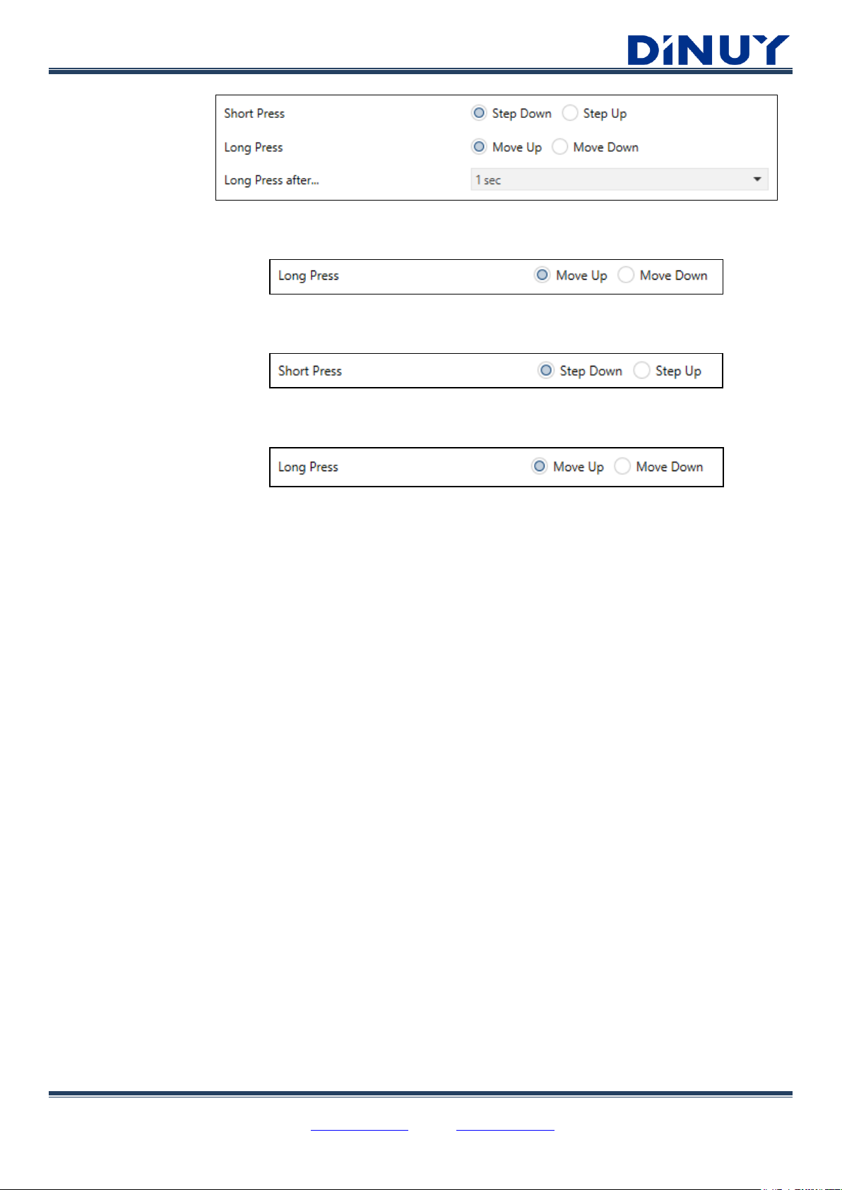
· Long Press after…: Sets the minimum time that a press should last to consider it as a long action.
· Long Press: action to be carried out when a long press is detected.
· Short Press: action to be carried out when a short press is detected.
DINUY S.A. c/Auzolan 2, 20303 Irun (Spain)
Tel.: +34943627988 – E-mail: knx@dinuy.com – Web: www.dinuy.com 10
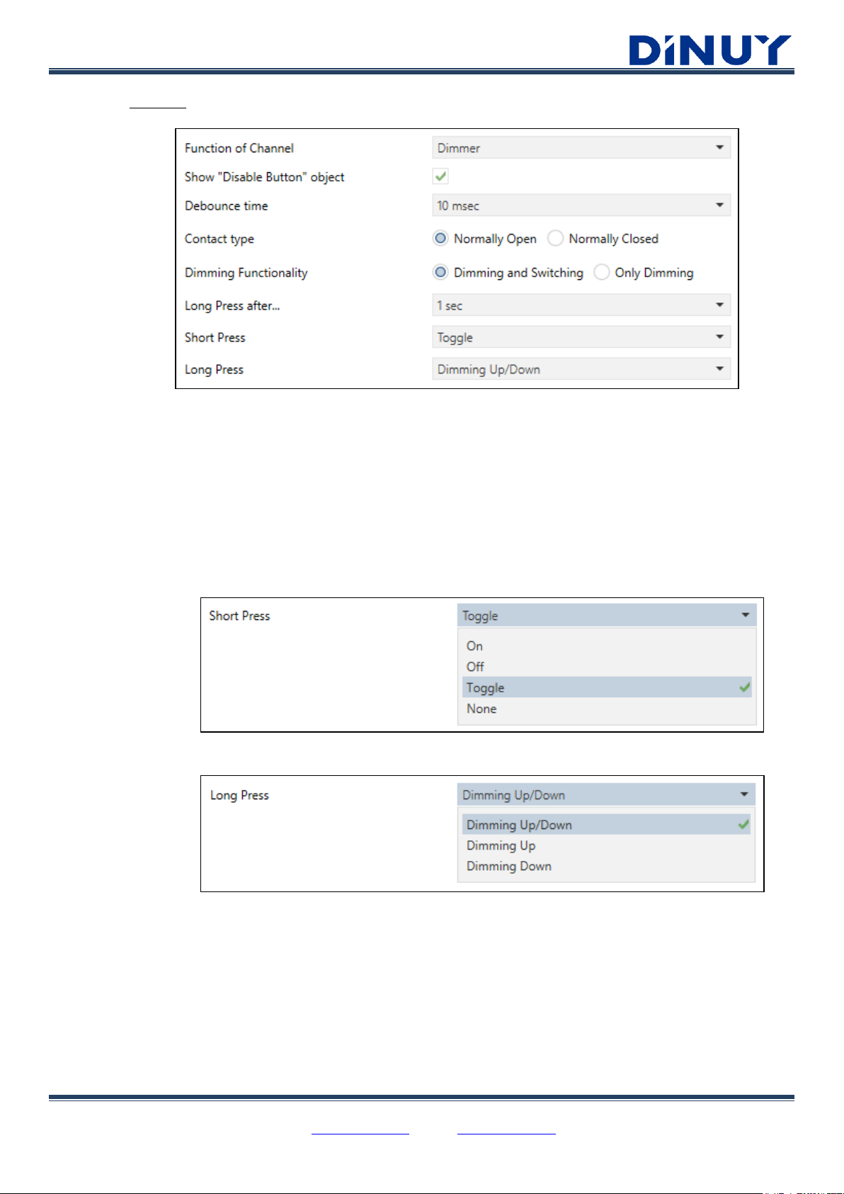
· Dimmer:
· Show “Disable Button” object: Allows activating/deactivating the key through the object "[PB] Disable
Button". Writing a "0" in this object, the key will be enabled, while if a "1" is written the key will be disabled
and will not send telegrams to the bus.
· Debounce time: Parameter to adjust the bounce suppression time when there is a switch. Prevents
multiple unwanted actions, caused by the rebound when a contact is closed.
· Contact type: Sets if it is a Normally Open or Normally Closed contact.
· Dimming Functionality: Allows selecting if only dimming telegrams will be sent or also switching ones.
· Long Press after…: Sets the minimum time that a press should last to consider it as a long action.
· Short Press: Action to be carried out when a short press is detected.
· Long Press: action to be carried out when a long press is detected.
DINUY S.A. c/Auzolan 2, 20303 Irun (Spain)
Tel.: +34943627988 – E-mail: knx@dinuy.com – Web: www.dinuy.com 11
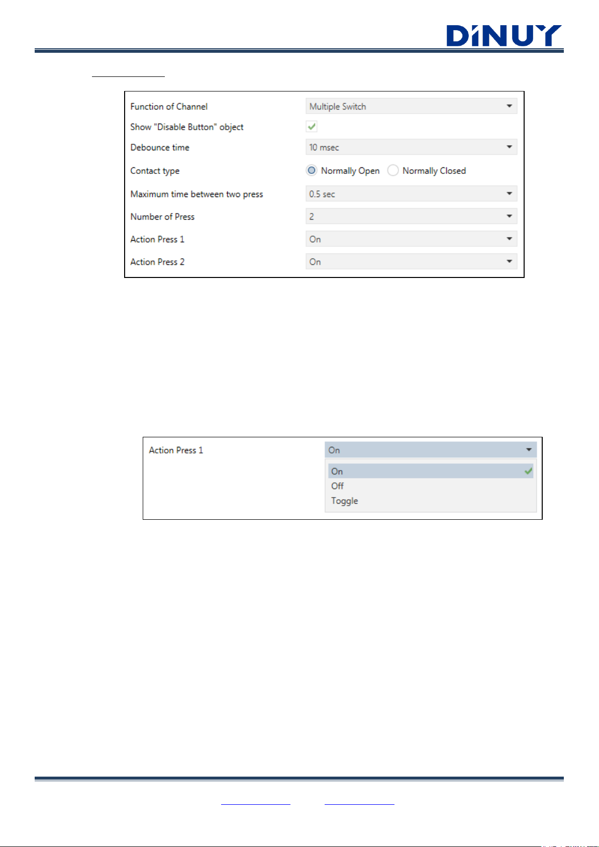
· Multiple Switch:
· Show “Disable Button” object: Allows activating/deactivating the key through the object "[PB] Disable
Button". Writing a "0" in this object, the key will be enabled, while if a "1" is written the key will be disabled
and will not send telegrams to the bus.
· Debounce time: Parameter to adjust the bounce suppression time when there is a switch. Prevents
multiple unwanted actions, caused by the rebound when a contact is closed.
· Contact type: Sets if it is a Normally Open or Normally Closed contact.
· Maximum time between two press: Maximum time between 2 consecutive press to understand that
they belong to the same sequence.
· Number of Press: Number of press which defines the sequence.
· Action Press 1..4: Function that performs each of the consecutive actions.
DINUY S.A. c/Auzolan 2, 20303 Irun (Spain)
Tel.: +34943627988 – E-mail: knx@dinuy.com – Web: www.dinuy.com 12
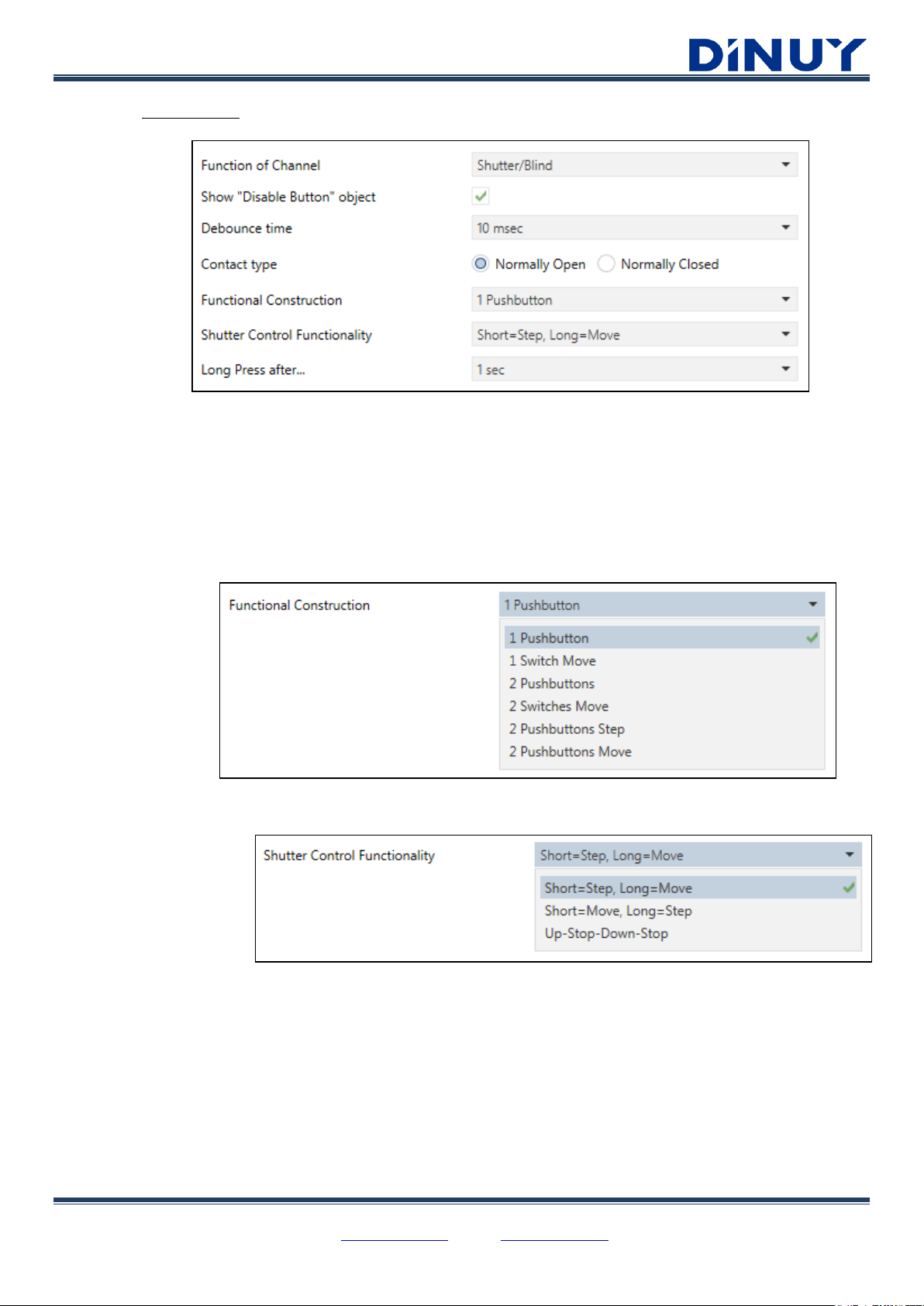
· Shutter/Blind:
· Show “Disable Button” object: Allows activating/deactivating the key through the object "[PB] Disable
Button". Writing a "0" in this object, the key will be enabled, while if a "1" is written the key will be disabled
and will not send telegrams to the bus.
· Debounce time: Parameter to adjust the bounce suppression time when there is a switch. Prevents
multiple unwanted actions, caused by the rebound when a contact is closed.
· Contact type: Sets if it is a Normally Open or Normally Closed contact.
· Functional Construction: Determines the operation of the key, such as Pushbutton or Switch, single or
double.
· 1 Pushbutton: sends Move Up/Down or Step telegrams, depending on the duration of the press.
This function is useful when a blind must be controlled from a single button.
· 1 Switch Move: sends Move Up/Down telegrams. This function is useful when a blind must be
controlled from a single switch. Step telegrams are not sent.
· 2 Pushbuttons: sends Move Up/Down or Step telegrams, depending on the duration of the press.
This function is useful when a blind must be controlled by two different buttons, one for Move Up and
another one for Move Down.
DINUY S.A. c/Auzolan 2, 20303 Irun (Spain)
Tel.: +34943627988 – E-mail: knx@dinuy.com – Web: www.dinuy.com 13
· 2 Switches Move sends Move Up/Down telegrams. This function is useful when a blind must be
controlled by two different switches, one for Move Up and another one for Move Down.
· 2 Pushbuttons Step: sends Step Up/Down telegrams. This function is useful when a blind must be
controlled by two different buttons, one for Step Up and another one for Step Down.
· 2 Pushbuttons Move: sends Move Up/Down telegrams. This function is useful when a blind must be
controlled by two different buttons, one for Move Up and another one for Move Down.
DINUY S.A. c/Auzolan 2, 20303 Irun (Spain)
Tel.: +34943627988 – E-mail: knx@dinuy.com – Web: www.dinuy.com 14
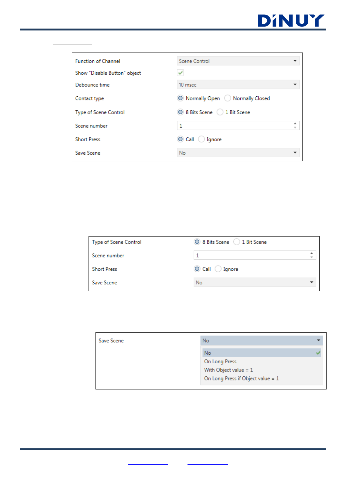
· Scene Control:
· Show “Disable Button” object: Allows activating/deactivating the key through the object "[PB] Disable
Button". Writing a "0" in this object, the key will be enabled, while if a "1" is written the key will be disabled
and will not send telegrams to the bus.
· Debounce time: Parameter to adjust the bounce suppression time when there is a switch. Prevents
multiple unwanted actions, caused by the rebound when a contact is closed.
· Contact type: Sets if it is a Normally Open or Normally Closed contact.
· Type of Scene Control:
o 8 Bits Scene:
▪ Scene number: assigns a Scene number to the input. It can be an 8-bit scene (1 – 64).
▪ Short Press: allows assigning a specific function to a short pressing: recover a scene or
ignore it.
▪ Save Scene:
▪ No: the Scene cannot be saved through the key.
▪ On Long Press: the Scene is saved after a long press.
▪ With Object value = 1: the scene is saved setting when the object “[PB] Long Press: Save
Scene” is “1”.
▪ On Long Press if Object value = 1: the scene is saved with a long pressing if the object “[PB]
Long Press: Save Scene” is “1”.
DINUY S.A. c/Auzolan 2, 20303 Irun (Spain)
Tel.: +34943627988 – E-mail: knx@dinuy.com – Web: www.dinuy.com 15
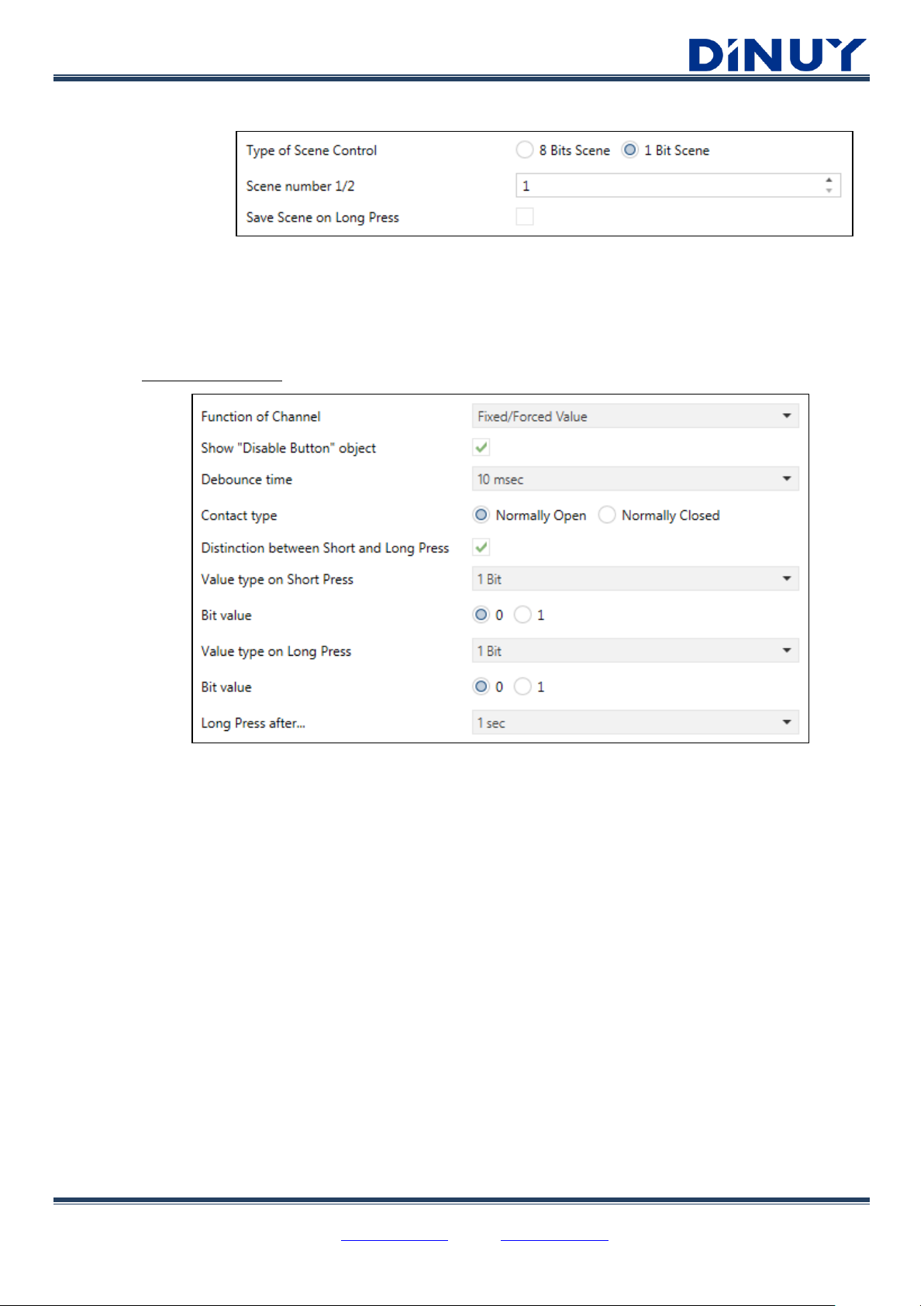
o 1 Bit Scene:
▪ Scene number 1/2: assigns a Scene number to the input. It can be an 1-bit (1 or 2) scene.
▪ Save Scene on Long Press: a long press will save the current Scene.
· Fixed/Forced Value:
· Show “Disable Button” object: Allows activating/deactivating the key through the object "[PB] Disable
Button". Writing a "0" in this object, the key will be enabled, while if a "1" is written the key will be disabled
and will not send telegrams to the bus.
· Debounce time: Parameter to adjust the bounce suppression time when there is a switch. Prevents
multiple unwanted actions, caused by the rebound when a contact is closed.
· Contact type: Sets if it is a Normally Open or Normally Closed contact.
· Distinction between Short and Long Press: allows to distinguish between a short and a long pressing.
This way, if the differentiation is made, two different actions can be carried out depending on the length of
the press. Two different objects will be available.
· Value type on Short Press: determines the type of value that will be sent via the object "[PB] Short
Press: X value".
· Value type on Long Press: determines the type of value that will be sent via the object "[PB] Long Press:
X value".
DINUY S.A. c/Auzolan 2, 20303 Irun (Spain)
Tel.: +34943627988 – E-mail: knx@dinuy.com – Web: www.dinuy.com 16
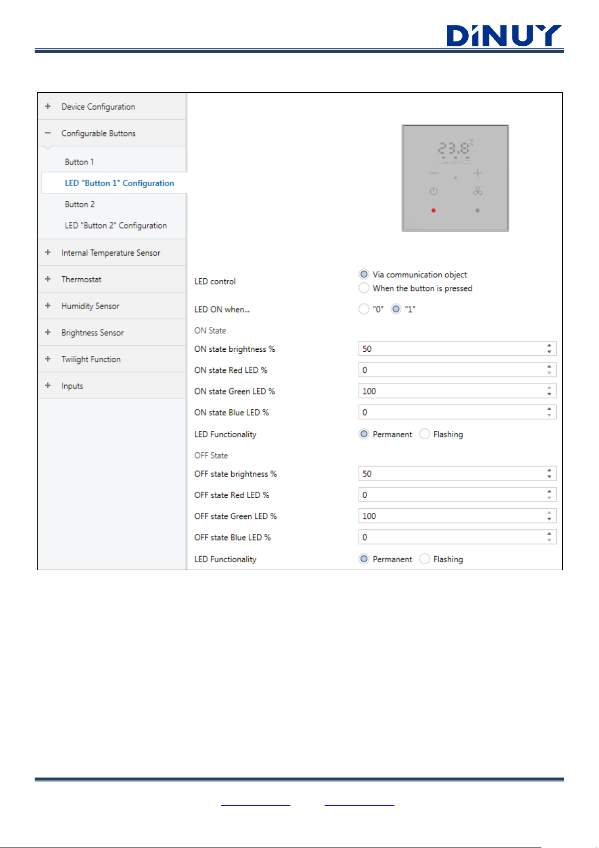
Configurable Buttons – LED Configuration
· LED control: Allows parameterizing the activation of the button’s LED.
o Via communication object: the object “[PB] LED “Button X” is enabled whereby the LED can be switched on
or off. It will also be possible to set the polarity of the object through the parameter "LED ON when...".
o When the button is pressed: the illumination of the key depends on whether it is physically pressed, or not.
· ON / OFF State: Determines the status of the LED: brightness level, RGB color and behavior, when the key is active or
not (object at 0/1 or the key is pressed / not pressed).
DINUY S.A. c/Auzolan 2, 20303 Irun (Spain)
Tel.: +34943627988 – E-mail: knx@dinuy.com – Web: www.dinuy.com 17
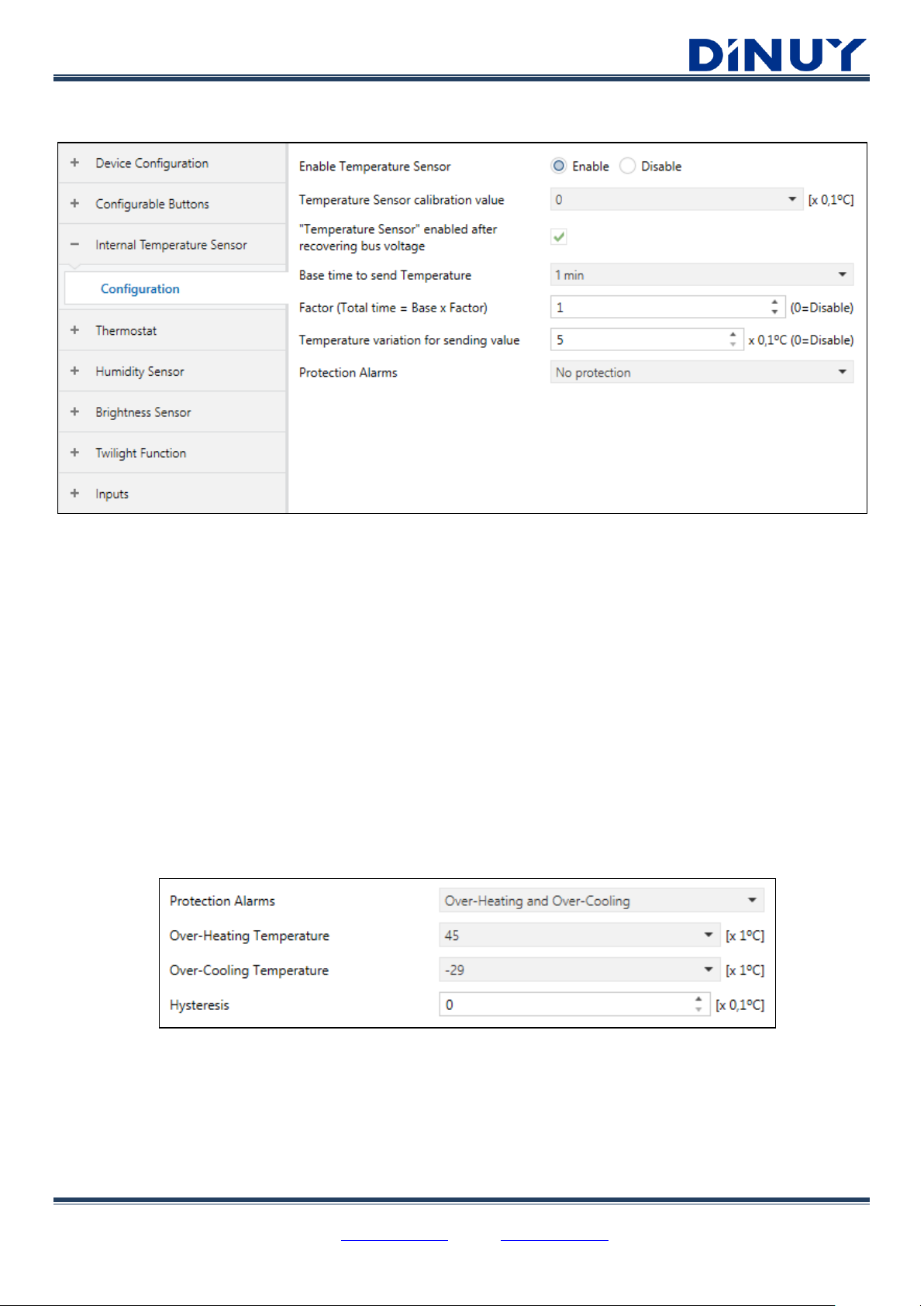
Internal Temperature Sensor
· Enable Temperature Sensor: The built-in temperature sensor can be enabled, or not, depending if it will used as the
temperature source for the Thermostat control.
· Temperature Sensor calibration value: A correction can be added or subtracted (between -5ºC and + 4.9ºC) to the
measurement received from the built-in sensor, in the event that there is a deviation between this value and the real
temperature of the room.
· “Temperature Sensor” enabled after recovering bus voltage: Determines if temperature sensor functionality will be
enabled after recovering bus voltage.
· Base time to send Temperature: How often the temperature value is sent. The time between each transmission results
from the multiplication "Base" x "Factor".
· Temperature variation for sending value: Measured temperature sending when it changes a certain value. If the
difference from the last measurement is higher than the set value, the temperature will be sent before the sending period
elapses.
· Protection Alarms:
· Over-Heating Temperature: When this value is reached the “[Temp] Temperature Sensor Over-Heating”
object is set to “1”.
· Over-Cooling Temperature: When this value is reached the “[Temp] Temperature Sensor Over-Cooling”
object is set to “1”.
· Hysteresis: A value, in tenths of a degree, to prevent successive resending of the object in case the
temperature fluctuates continuously around the threshold.

DINUY S.A. c/Auzolan 2, 20303 Irun (Spain)
Tel.: +34943627988 – E-mail: knx@dinuy.com – Web: www.dinuy.com 18
Thermostat
The parameters are divided into 3 defined blocks:
o Configuration: a series of general parameters should be configured (thermostat type, temperature source, window
alarm…).
o Cooling / Heating Set-point: the parameters related to the Heating or Cooling Setpoint are set.
o Fan-Coil Control: Fan-Coil control parameters.

DINUY S.A. c/Auzolan 2, 20303 Irun (Spain)
Tel.: +34943627988 – E-mail: knx@dinuy.com – Web: www.dinuy.com 19
Thermostat - Configuration:
· Enable Thermostat: enable/disable the Thermostat functionality.
· Mode: which of the two main climate working modes will be available, so that the thermostat can manage situations of hot,
cool, or both, respectively.
· Set-point mode: cooling or heating setpoint temperature can be set according to two modes: Absolute or Relative.
· Initial Set-point after recovering bus voltage: sets the initial setpoint after the bus voltage is recovered.
· If “Absolute Set-point mode” has been selected, this value will be the initial setpoint.
· If “Relative Set-point mode” has been selected, this value will be the initial setpoint for the Comfort mode.
· Enable Window protection: activates/deactivates protection mode in the event of an unusual situation, for example, an
open or broken window. It is a protection in preference to the rest of the modes, therefore no other special mode can be
activated until the Window Alarm Input changes to "0".
Once this option is enabled, there are four 1-bit objects "[Th] Window Alarm 1..4 Input" that allow monitoring up to 4
different windows.
· Enable 1 Bit mode objects: allows to select the desired mode through 4 different 1-bit objects "[Th] Special mode
Comfort / Stand-by / Economy / Protection".
However, there is a 1-byte input object “[Th] Special mode Input 1 Byte” by default. This object acts over all the bits at
the same time and would overlap what has been written with the 1-bit objects. 1-bit objects only write to their mode bit.
It can take the following values:
· 00: Auto
· 01: Comfort
· 02: Stand-by
· 03: Economy
· 04: Protection
The four 1-bit objects can work in 2 different ways:
- Switch mode: setting “1” to any of the four 1-Bit objects, the corresponding special mode will be activated. The
"0" deactivates the corresponding mode. If a “1” is set in one bit, and then another “1” in another bit, the one
with the highest priority will be activated. To remove the “1” from a bit, a “0” must be sent. The order of
priority is as follows: Protection > Comfort > Stand-by > Economy.
- Trigger mode: setting “1” to any of the four 1-Bit objects, the corresponding special mode will be activated. The
“0” will have no function. By setting a “1” to one bit, as soon as the mode is activated it is automatically set to
“0”, so if another bit is then activated to “1”, there will not be two bits to “1”, only the last one.

DINUY S.A. c/Auzolan 2, 20303 Irun (Spain)
Tel.: +34943627988 – E-mail: knx@dinuy.com – Web: www.dinuy.com 20
· Reference Temperature Source: sets the source of the temperature value to be taken as the reference. This value can
come from a single source, through the 2-byte object “[Th] Temperature Sensor 1”, or from the combination of 2 objects in
the set proportions. This second value will be established by the 2-byte object: “[Th] Temperature Sensor 2”.
· Thermostat always On: it defines if the thermostat will always remain on or if the possibility of switching on/off is given. If
this option is not marked, two 1-bit objects will be enabled to activate it: “[Th] On / Off Input” and “[Th] On / Off
Feedback”. In addition, there will be 2 more parameters to be parameterized:
· State after recovering bus voltage: sets the state the thermostat will return when the bus voltage is
restored.
· Enable Turn-on Thermostat when Special commands arrive: in case the thermostat is turned off, it will
automatically turn on when an activation order of a special mode arrives.
· Send Thermostat Mode after recovering bus voltage: establishes the sending, or not, of the Mode in which the
Thermostat is after recovering the bus voltage.
· Enable automatic mode change: defines if the Thermostat changes automatically from one mode to the other one
(Heating / Cooling) depending on the setpoint and reference temperatures, or if the change is made manually, through
the object "[Th] Heating or Cooling Mode".
If the change is made manually, a “0” in the object “[Th] Heating or Cooling Mode” will activate the Cooling mode, and a
“1” will activate the Heating mode.
If on the contrary, the change is made automatically:
· Reference Temperature > Cooling Setpoint → Cooling mode
· Reference Temperature < Heating Setpoint → Heating mode
· Thermostat Type after recovering bus voltage: defines the thermostat operating mode, Heating / Cooling, after
bus voltage recovery.
· Control object: establishes if there is only one output object, “[Th] Output”, or if there are different objects for each
mode, “[Th] Heating Output” and “[Th] Cooling Output”. This parameter will only be available in the TM KNT 002
model (with Modes).

DINUY S.A. c/Auzolan 2, 20303 Irun (Spain)
Tel.: +34943627988 – E-mail: knx@dinuy.com – Web: www.dinuy.com 21
Thermostat – Set-points:

DINUY S.A. c/Auzolan 2, 20303 Irun (Spain)
Tel.: +34943627988 – E-mail: knx@dinuy.com – Web: www.dinuy.com 22
Heating / Cooling Set-point
Absolute Set-point mode
o The setpoints for cooling or heating are defined as absolute values. Total control over the desired temperature in the room
is achieved, since the thermostat regulates the room temperature based on the temperature setpoint set every moment.
o Via the 2-byte communication object “[Th] Set-point Input” the desired temperature is set through the bus. Depending on
the set value and the parameterized setpoints for each special mode, one mode or another will be established.
o A setpoint value is also defined for the Comfort special mode, from which the setpoints of the other special modes will be
defined: Stand-by and Economy.
o Protection mode, of heating or cooling, is defined in absolute values.
Economy (Cool) ----------------------------------------------------------------------------------
Stand-by (Cool) ----------------------------------------------------------------------------------
Comfort (Cool) ----------------------------------------------------------------------------------
Set-Point (Auto) --------------------------------------------------------------------------------
Comfort (Heat) ----------------------------------------------------------------------------------
Stand-by (Heat) ----------------------------------------------------------------------------------
Economy (Heat) ----------------------------------------------------------------------------------
▪ Comfort Set-point: The temperature under this special mode must guarantee the comfort of the people
present in the room. This mode is intended to perform usual climate control when the room is being occupied.
▪ Set-point Offset for Stand-by mode: This mode is intended for short periods during which the room remains
empty. A standby or standby temperature is enabled that will allow energy savings. This value should be set by
means of an offset relative to the absolute setpoint defined for the Comfort mode according to the parameterized
operating mode (cooling, heating or both, in which case it will be necessary to define a Comfort setpoint for

DINUY S.A. c/Auzolan 2, 20303 Irun (Spain)
Tel.: +34943627988 – E-mail: knx@dinuy.com – Web: www.dinuy.com 23
heating and another for cooling). This mode is usually used when the room is going to be empty for a short period
of time.
▪ Set-point Offset for Economy mode: This mode is usually used when the air-conditioned room is going to be
empty for longer periods of time. This value will be set by means of an offset relative to the absolute setpoint
defined for the Comfort mode according to the parameterized operating mode (cooling, heating or both, in which
case it will be necessary to define a Comfort setpoint for heating and another for cooling).
▪ Protection Set-point: This value will be activated in case of adverse climate conditions, excessive heat or cold,
mainly due to some unusual external situation (such as a broken window) or because the room is going to remain
empty for a long time. The thermostatic control will only be activated if the thermostat is on and with the
protection mode activated and when the room temperature is actually above or below the parameterized
protection setpoints, thus avoiding excessive energy consumption.
Relative Mode Set-point
o It consists of the application of set-points in relative terms, that is, a Comfort set-point temperature will be set by
parameter and each of the set-points of the modes is configured by a relative offset with respect to this base reference,
both for cooling and for heating.
o With the 2-byte communication object "[Th] Comfort Set-point Input" the Comfort set-point is set via bus, which will
be taken as a reference to define the other special modes.
o Protection mode, for heating or cooling, is defined in absolute values.
Economy (Cool) -----------------------------------------------------------------------------------
Stand-by (Cool) -----------------------------------------------------------------------------------
Comfort Set-point ---------------------------------------------------------------------------------
Stand-by (Heat) -----------------------------------------------------------------------------------
Economy (Heat) -----------------------------------------------------------------------------------
▪ Initial Comfort Set-point after recovering bus voltage: Initial setpoint for Comfort mode which will be
taken as base reference for the other modes, with the exception of Protection mode.

DINUY S.A. c/Auzolan 2, 20303 Irun (Spain)
Tel.: +34943627988 – E-mail: knx@dinuy.com – Web: www.dinuy.com 24
▪ Offset for Stand-by Set-point mode: This value will be set by a relative offset from the absolute setpoint
defined for the Comfort mode according to the parameterized operating mode (cool, heat or both, in which case
it will be necessary to define a Comfort setpoint for heating and another for cooling). This mode is usually used
when the room is going to be empty for a short period of time. A standby temperature is enabled allowing energy
savings.
▪ Offset for Economy Set-point mode: This value will be set by a relative offset from the absolute setpoint
defined for the Comfort mode according to the parameterized operating mode (cool, heat or both, in which case
it will be necessary to define a Comfort setpoint for heating and another for cooling). This mode is usually used
when the room is going to be empty for longer periods of time, for example, when people will not use the room
again until the next day.
▪ Protection Set-point: This value will be activated in case of adverse climate conditions, excessive heat or cold,
mainly due to some abnormal external situation (such as a broken window) or because the room is going to
remain empty for a long time. The thermostatic control will only be activated if the thermostat is on and with the
protection mode activated and when the room temperature is really above or below the parameterized
protection setpoints, thus avoiding excessive energy consumption.

DINUY S.A. c/Auzolan 2, 20303 Irun (Spain)
Tel.: +34943627988 – E-mail: knx@dinuy.com – Web: www.dinuy.com 25
Thermostat – Regulation Mode (TM KNT 002):
• Thermostatic control can be carried out in 2 different algorithms:
▪ 2-point Hysteresis Control.
▪ PI control.
2-point Hysteresis Control
It is a simple control method, widely used in conventional thermostats, where the Set-point Temperature and two values of
hysteresis around the setpoint are required. It prevents a continuous switching between the two modes.

DINUY S.A. c/Auzolan 2, 20303 Irun (Spain)
Tel.: +34943627988 – E-mail: knx@dinuy.com – Web: www.dinuy.com 26
PI Control (Proportional – Integral)
More advanced and accurate linear control than the 2-point hysteresis control, since besides taking into account the difference
between the temperature setpoint and the actual temperature, it takes into account previous states or differences.
% Output = % Temperature Difference + % Integral
Where:
% Temperature Difference = (Current Temperature – Temperature Set-point) / Proportional Band (K)
% Integral:
· Maximum integral component (%): limits the maximum value of % Integral. It depends on how the real
temperature approaches the Setpoint.
· Attenuation factor: atenúa el % Integral. the higher this value, the % Integral will have less weight.
In this way, the oscillations with respect to the setpoint value are reduced and the ambient temperature becomes progressively
stable around the setpoint.

DINUY S.A. c/Auzolan 2, 20303 Irun (Spain)
Tel.: +34943627988 – E-mail: knx@dinuy.com – Web: www.dinuy.com 27
▪ PWM Type:
▪ PWM (1 Bit): control by Pulse Width Modulation. One 1-Bit object “[Th] Cooling / Heating Output” will
be available to control on/off valves, not allowing intermediate positions. Therefore, partial opening of the
valve is emulated by opening and closing it for similar portions of time.
▪ 1 Byte (%): the control object “[Th] Cooling / Heating Output” will be a 1-Byte percentage value. It will
indicate how much (%) the valve should open, as long as the valve admits this positioning.
▪ PI Cycle Time: this time is considered for setting the temperature sampling frequency and therefore the update
frequency of the control signal. High values should be selected for systems with high thermal inertia (~ 20min) and
lower values for systems with lower thermal inertia (~10min).
▪ Proportional Band: resulting value between the setpoint temperature and the actual temperature from which
the proportional integral value will be applied.
o If the difference between the actual temperature and the setpoint temperature is higher than the parameter
"Proportional band", the Thermostat output will be 100%.
o If the difference between the actual temperature and the setpoint temperature is lower than the parameter
"Proportional band", the Thermostat output will be the result of the addition of two values:
▪ Proportional value: The Proportional value (rule of three) between the difference "Setpoint
temperature" - "Actual temperature" in the case of heating thermostat, or "Actual temperature" "Setpoint temperature" in the case of cooling thermostat, with respect to the parameter "Proportional
band".
▪ Integral value: This value is the result of adding the difference between the “Actual Temperature” and
the “Setpoint temperature” in each integration cycle. The "Attenuation Factor" is applied to this sum
and the resulting value is added to the "Proportional Value" if it is less than the "Maximum Integral
Component" value. Otherwise, the value "Maximum Integral Component" is added.
The result can never be higher than 100%.
▪ Attenuation factor: attenuation that is applied to the Integral value before adding it to the Proportional value.
▪ Maximum Integral component (%): Integral value limitation.

DINUY S.A. c/Auzolan 2, 20303 Irun (Spain)
Tel.: +34943627988 – E-mail: knx@dinuy.com – Web: www.dinuy.com 28
Thermostat – Fan-Coil Control (TM KNT 001):
The Fan-Coil is a system that controls the flow of cooling / heating fluid through a valve (2 tubes) or two valves (4 tubes).
The liquid exchanges heat / cold with the environment through a ventilation system controlled by a fan, which can usually be
enabled 3 different velocities.
· “Fan On/Off” object ON after recovering bus voltage: Allows switching the Fan ON through the object “[Fancoil]
Fan On (Auto) / Off” after recovering the bus voltage. It would start in Auto speed.
· Heat / Cool System: Establishes the number of pipes of the Fan-Coil, 2 pipes (1 valve: heating or cooling) or 4 pipes (2
valves: heating and cooling).
· Fan-Coil Type: Fan-coil control by On/Off or PI control.

DINUY S.A. c/Auzolan 2, 20303 Irun (Spain)
Tel.: +34943627988 – E-mail: knx@dinuy.com – Web: www.dinuy.com 29
Fan-Coil On/Off Control
· Fan-Coil Speed Output objects: Sets the speed control of the Fan-coil, independently or cumulatively way. The object
number is the same in both cases.
· Valve independent control: In the On / Off Control mode of the Fan-Coil it is possible to have the possibility of opening
or closing the Valve independently of the Fan. In this way, the Valve can be kept open, when the real temperature is close to
the setpoint, without the need of being the Fan On and avoiding unnecessary noise.
o If it is NOT done an independent control of the Valve and it is a 2-pipe system:
· Forwarding period (0=Disable): How often is the Fan Speed and Valve status sent.

DINUY S.A. c/Auzolan 2, 20303 Irun (Spain)
Tel.: +34943627988 – E-mail: knx@dinuy.com – Web: www.dinuy.com 30
HEATING – FAN SPEED SETTING
COOLING – FAN SPEED SETTING

DINUY S.A. c/Auzolan 2, 20303 Irun (Spain)
Tel.: +34943627988 – E-mail: knx@dinuy.com – Web: www.dinuy.com 31
o If it is done an independent control of the Valve and it is a 2-pipe system:
· Forwarding period (0=Disable): How often is the Fan Speed and Valve status sent.

DINUY S.A. c/Auzolan 2, 20303 Irun (Spain)
Tel.: +34943627988 – E-mail: knx@dinuy.com – Web: www.dinuy.com 32
HEATING – FAN SPEED SETTING
COOLING – FAN SPEED SETTING
o 4 pipes System: The operation is similar to the control of a 2-pipe system, but in this case, there are 2 independent
Valves, one for the control of Heating, and another for Cooling.

DINUY S.A. c/Auzolan 2, 20303 Irun (Spain)
Tel.: +34943627988 – E-mail: knx@dinuy.com – Web: www.dinuy.com 33
Fan-Coil and Valve PI Control
The logic and parameters are similar to the used in the On/Off Control, but in this case, a 1-Byte object is available to carry
out the control.
In this type of control, for both the Valve and the Fan, it is necessary to set several parameters:
▪ PI Cycle Time: this time is considered for setting the temperature sampling frequency and therefore the update
frequency of the control signal. High values should be selected for systems with high thermal inertia (~ 20min) and lower
values for systems with lower thermal inertia (~10min).
▪ Proportional Band: resulting value between the setpoint temperature and the actual temperature from which the
proportional integral value will be applied.
• If the difference between the actual temperature and the setpoint temperature is higher than the parameter
"Proportional band", the Fan-coil output will be 100%.
• If the difference between the actual temperature and the setpoint temperature is lower than the parameter
"Proportional band", the Fan-coil output will be the result of the addition of two values:
▪ Proportional value: The Proportional value (rule of three) between the difference "Setpoint temperature" -
"Actual temperature" in the case of heating thermostat, or "Actual temperature" - "Setpoint temperature"
in the case of cooling, with respect to the parameter "Proportional band".
▪ Integral value: This value is the result of adding the difference between the “Actual Temperature” and the
“Setpoint temperature” in each integration cycle. The "Attenuation Factor" is applied to this sum and the
resulting value is added to the "Proportional Value" if it is less than the "Maximum Integral Component"
value. Otherwise, the value "Maximum Integral Component" is added.
The result can never be higher than 100%.
▪ Attenuation factor: attenuation that is applied to the Integral value before adding it to the Proportional value.
▪ Maximum Integral component (%): Integral value limitation

DINUY S.A. c/Auzolan 2, 20303 Irun (Spain)
Tel.: +34943627988 – E-mail: knx@dinuy.com – Web: www.dinuy.com 34
Humidity Sensor:
An internal Relative Humidity Sensor is available:
· Enable Humidity Sensor: Allows enabling the functionality of the internal Humidity sensor. However, the object “[Hum]
Disable Humidity Sensor” will be available and it will allow enabling (0) or not (1) this sensor.
· Humidity Sensor calibration Sign / Value: Defines an offset to be applied to the measurement received from the sensor
to correct possible deviations.
· “Humidity Sensor” enabled after recovering bus voltage: Sets whether the Humidity sensor will be enabled after the
start-up. If this parameter is not enabled, the Humidity functionality would be disabled after a power failure.
· Base time to send Humidity: Sets every how much time the object “[Hum] Humidity Value” will be sent to the bus.
· Humidity variation for sending value: Defines a threshold so that if a new reading of the current humidity is found to
differ from the last value sent to the bus higher than such threshold, a new sending will take place and the sending period will
be restarted. The value “0” disables this sending.
· Protection Alarms:
· High Humidity Alarm: Maximum Humidity permitted. Humidity values greater than this will be considered
over-humidity, and therefore a “1” will be periodically sent through object “[Hum] High Humidity Alarm”.
· Low Humidity Alarm: Minimum Humidity permitted. Humidity values lower than this will be considered under-
humidity, and therefore a “1” will be periodically sent through object “[Hum] Low Humidity Alarm”.
· Hysteresis: Threshold around the over- and under-humidity defined above. This dead band prevents the device
from sending the over- and under-humidity alarm and no-alarm over and over when the current humidity keeps
fluctuating around the limit.

DINUY S.A. c/Auzolan 2, 20303 Irun (Spain)
Tel.: +34943627988 – E-mail: knx@dinuy.com – Web: www.dinuy.com 35
Brightness Sensor:
An internal Brightness Sensor is also available.
· Enable Brightness Sensor: Allows enabling the functionality of the internal Brightness sensor.
· Time base for cyclic transmission: Sets every how much time the object “[Lux] Brightness Value” will be sent to the
bus.
· Activate object “Brightness Sensor Disable”: The object “[Lux] Enable Brightness Sensor” will be available to enable
(0) or not (1) the functionality of this sensor.
· Enable Brightness Sensor with: Sets the polarity of the object “[Lux] Enable Brightness Sensor”.
· Object “Enable Brightness Sensor” state: Sets whether the Brightness sensor will be enabled after the start-
up. If this parameter is not enabled, the Brightness functionality would be disabled after a power failure.

DINUY S.A. c/Auzolan 2, 20303 Irun (Spain)
Tel.: +34943627988 – E-mail: knx@dinuy.com – Web: www.dinuy.com 36
Twilight Function:
It is possible to enable a Twilight Function associated with the Brightness measured by its internal sensor.
· Twilight Function: Allows enabling the Twilight functionality. However, the object “[Twil] Enable Twilight Function” will
be available and it will allow enabling (0) or not (1) this functionality.
· Type of Twilight object: Defines the value type will be sent via the output object “[Twil] Twilight Function”.
· Sending at Upper Threshold: Sets the value which will be sent when the Upper Threshold is reached.
· Sending at Lower Threshold: Sets the value which will be sent when the Lower Threshold is reached.
· Time base for cyclic transmission: Determines every how much time the object “[Twil] Twilight Function” will be sent
to the bus.
· Upper Threshold (Lux): Upper Lux threshold value.
· Lower Threshold (Lux): Lower Lux threshold value.
· Activate object “Enable Twilight Function”: The object “[Twil] Enable Twilight Function” will be available to enable (0)
or not (1) this functionality.
· Enable Twilight Function with: Sets the polarity of the object “[Twil] Enable Twilight Function”.
· Object “Enable Twilight Function” state: Sets whether the Twilight function sensor will be enabled after the
start-up. If this parameter is not enabled, the Twilight functionality would be disabled after a power failure.

DINUY S.A. c/Auzolan 2, 20303 Irun (Spain)
Tel.: +34943627988 – E-mail: knx@dinuy.com – Web: www.dinuy.com 37
Inputs:
Four Inputs are available in the back side of the Thermostat.
They can be enabled to manage the connection of a Door/Window Contact reed or a DINUY Temperature Probe (ST KNT
001 or ST KNT 002).
· Door/Window Contact Functionality: Up to 4 free-voltage Door/Window Contacts can be connected to the inputs.
· Window Contact polarity: Sets if it is a normally closed or normally open contact.
· Functionality enabled after recovering bus voltage: The input can be automatically enabled after recovering
bus voltage. In the event that this parameter is not enabled, the functionality should be enabled via the object “[InX]
Disable Input” after the voltage is restored.
· Base time to refresh value: Sets every how much time the “[InX] Window state” object would be sent to the
bus. The value “0” leaves this periodical sending disabled.

DINUY S.A. c/Auzolan 2, 20303 Irun (Spain)
Tel.: +34943627988 – E-mail: knx@dinuy.com – Web: www.dinuy.com 38
· Temperature Sensor Functionality: Up to 4 DINUY Temperature Probes (ST KNT 001 or ST KNT 002) can be
connected to the inputs. In this way, the measured temperature can be used as a second source in the Thermostat function.
· Functionality enabled after recovering bus voltage: The input can be automatically enabled after recovering
bus voltage. In the event that this parameter is not enabled, the functionality should be enabled via the object “[InX]
Disable Input” after the voltage is restored.
· Base time to refresh value: Sets every how much time the “[InX] Sensor Temperature Value” object would be
sent to the bus. The value “0” leaves this periodical sending disabled.
· Temperature Sensor calibration value: Defines an offset to be applied to the measurement received from the
sensor to correct possible deviations.
· Temperature variation for sending value: Defines a threshold so that if a new reading of the current
temperature is found to differ from the last value sent to the bus higher than such threshold, a new sending will take
place and the sending period will be restarted. The value “0” disables this sending.
· Protection Alarms:
· Over-Heating Temperature: Maximum Temperature permitted. Temperature values greater than this
will be considered over-heating, and therefore a “1” will be periodically sent through object “[InX]
Temperature Sensor Over-Heating”.
· Over-Cooling Temperature: Minimum Temperature permitted. Temperature values lower than this will
be considered over-cooling, and therefore a “1” will be periodically sent through object “[InX]
Temperature Sensor Over-Cooling”.
· Hysteresis: Threshold around the over-heating and over-cooling defined above. This dead band prevents
the device from sending the over-heating and over-cooling alarm and no-alarm over and over when the
current temperature keeps fluctuating around the limit.

DINUY S.A. c/Auzolan 2, 20303 Irun (Spain)
Tel.: +34943627988 – E-mail: knx@dinuy.com – Web: www.dinuy.com 39
Communication Objects
Configurable Buttons Objects
Switch:
Number
Name
Function
Description
24, 30
[PB1..2] Disable Button
1 = Disable; 0 = Enable
Allows disabling the functionality of the button 1 or 2
25, 31
[PB1..2] Short Press: Switch
1 = On; 0 = Off
Output Switch object after a short press
26, 32
[PB1..2] Long Press: Switch
1 = On; 0 = Off
Output Switch object after a long press
29, 35
[PB1..2] LED “Button 1..2”
0 = Off; 1 = On
Input object for the control of each LED

DINUY S.A. c/Auzolan 2, 20303 Irun (Spain)
Tel.: +34943627988 – E-mail: knx@dinuy.com – Web: www.dinuy.com 40
Dimmer:
Number
Name
Function
Description
24, 30
[PB1..2] Disable Button
1 = Disable; 0 = Enable
Allows disabling the functionality of the button 1 or 2
25, 31
[PB1..2] Press
1 = On; 0 = Off
Output Switch object after a short press
26, 32
[PB1..2] Long Press: Dimming
Dimming control
Output Dimming object after a long press
29, 35
[PB1..2] LED “Button 1..2”
0 = Off; 1 = On
Input object for the control of each LED

DINUY S.A. c/Auzolan 2, 20303 Irun (Spain)
Tel.: +34943627988 – E-mail: knx@dinuy.com – Web: www.dinuy.com 41
Multiple Switch:
Number
Name
Function
Description
24, 30
[PB1..2] Disable Button
1 = Disable; 0 = Enable
Allows disabling the functionality of the button 1 or 2
25, 26, 27, 28,
31, 32, 33, 34
[PB1..2] Press 1..4
1 = On; 0 = Off
Output object to switch on or off after a press and taking into
account the sequence
29, 35
[PB1..2] LED “Button 1..2”
0 = Off; 1 = On
Input object for the control of each LED

DINUY S.A. c/Auzolan 2, 20303 Irun (Spain)
Tel.: +34943627988 – E-mail: knx@dinuy.com – Web: www.dinuy.com 42
Shutter / Blind:
Number
Name
Function
Description
24, 30
[PB1..2] Disable Button
1 = Disable; 0 = Enable
Allows disabling the functionality of the button 1 or 2
25, 31
[PB1..2] Short Press: Blind Step/Stop
0 = Step Up / Stop; 1 = Step Down / Stop
Output object to carry out a step up or down, or stop, on the
blind / shutter after a short press
26, 32
[PB1..2] Long Press: Move Blind
0 = Up; 1 = Down
Output object to carry out a move up or down on the blind /
shutter after a long press
29, 35
[PB1..2] LED “Button 1..2”
0 = Off; 1 = On
Input object for the control of each LED

DINUY S.A. c/Auzolan 2, 20303 Irun (Spain)
Tel.: +34943627988 – E-mail: knx@dinuy.com – Web: www.dinuy.com 43
Scene Control:
Number
Name
Function
Description
24, 30
[PB1..2] Disable Button
1 = Disable; 0 = Enable
Allows disabling the functionality of the button 1 or 2
25, 31
[PB1..2] Short Press: Send Scene
8-Bit Scene Control
0 = Scene 1; 1 = Scene 2
Output object to activate a Scene after a short press
26, 32
[PB1..2] Long Press: Save Scene
0 = No action; 1 = Save Scene
0 = Save Scene 1; 1 = Save Scene 2
Output object to save a Scene after a long press
29, 35
[PB1..2] LED “Button 1..2”
0 = Off; 1 = On
Input object for the control of each LED

DINUY S.A. c/Auzolan 2, 20303 Irun (Spain)
Tel.: +34943627988 – E-mail: knx@dinuy.com – Web: www.dinuy.com 44
Fixed / Forced Value:
Number
Name
Function
Description
24, 30
[PB1..2] Disable Button
1 = Disable; 0 = Enable
Allows disabling the functionality of the button 1 or 2
25, 31
[PB1..2] Pulsación Corta: Valor 1 Bit / 2 Bits /
1 Byte / 2 Bytes con signo / 2 Bytes / 2 Bytes
flotante / 4 Bytes
Envío Valor 1 Bit / 2 Bits / 1 Byte / 2 Bytes con signo /
2 Bytes / 2 Bytes flotante / 4 Bytes
Output object to send a set value after a short press
26, 32
[PB1..2] Pulsación Larga: Valor 1 Bit / 2 Bits /
1 Byte / 2 Bytes con signo / 2 Bytes / 2 Bytes
flotante / 4 Bytes
Envío Valor 1 Bit / 2 Bits / 1 Byte / 2 Bytes con signo /
2 Bytes / 2 Bytes flotante / 4 Bytes
Output object to send a set value after a long press
29, 35
[PB1..2] LED “Button 1..2”
0 = Off; 1 = On
Input object for the control of each LED

DINUY S.A. c/Auzolan 2, 20303 Irun (Spain)
Tel.: +34943627988 – E-mail: knx@dinuy.com – Web: www.dinuy.com 45
Internal Temperature Sensor Objects
Number
Name
Function
Description
48
[Temp] Disable Temperature Sensor
1 = Disable; 0 = Enable
Allows disabling the functionality of the internal temperature
sensor
49
[Temp] Temperature Value
Temperature Value
2-Byte measured temperatura object
50
[Temp] Temperature Sensor Over-Heating
1 = Over-Heating; 0 = No Over-Heating
Alarm over-heating output object
51
[Temp] Temperature Sensor Over-Cooling
1 = Over-Cooling; 0 = No Over-Cooling
Alarm over-cooling output object

DINUY S.A. c/Auzolan 2, 20303 Irun (Spain)
Tel.: +34943627988 – E-mail: knx@dinuy.com – Web: www.dinuy.com 46
Thermostat Objects
TM KNT 002 (with HVAC Special Modes):

DINUY S.A. c/Auzolan 2, 20303 Irun (Spain)
Tel.: +34943627988 – E-mail: knx@dinuy.com – Web: www.dinuy.com 47
Number
Name
Function
Description
52
[Th] On/Off Feedback
1 = On; 0 = Off
If the Thermostat is not always on (set by parameter), this 1-Bit
object allows knowing it state
53
[Th] On/Off
1 = On; 0 = Off
If the Thermostat is not always on (set by parameter), this 1-Bit
object allows switching it on/off
54
[Th] Set-point Feedback
Current set-point
Fixed temperature set-point
55
[Th] Set-point Input
[Th] Comfort Set-point Input
Set-point
Comfort set-point
Set-point input object. If "Relative Set-point Mode" is selected,
this value will be the Comfort Mode Set-point
56
[Th] Heating Output
Output (2-point with Hysteresis)
Output (% Proportional - Integral)
Output (PWM Proportional - Integral)
Output object for Valve control. It can be a 1-Bit or 1-Byte value,
depending on whether the control is done by PWM or by
percentages
57
[Th] Cooling Output
Output (2-point with Hysteresis)
Output (% Proportional - Integral)
Output (PWM Proportional - Integral)
Output object for Valve control. It can be a 1-Bit or 1-Byte value,
depending on whether the control is done by PWM or by
percentages
58
[Th] Temperature Sensor 1
Input Temperature Sensor 1
Input temperature value from a sensor
59
[Th] Temperature Sensor 2
Input Temperature Sensor 2
Input temperature value from a sensor
60
[Th] Special Mode Feedback
2 Bytes Mode Feedback
Information about the Special state of the Thermostat
61
[Th] Special mode Input 1 Byte
HVAC 1 Byte Mode
1-Byte input object to select a Special mode
62
[Th] Special mode Economy
0 = Off; 1 = On
1-Bit input object to activate a Special mode
63
[Th] Special mode Stand-by
0 = Off; 1 = On
64
[Th] Special mode Protection
0 = Off; 1 = On

DINUY S.A. c/Auzolan 2, 20303 Irun (Spain)
Tel.: +34943627988 – E-mail: knx@dinuy.com – Web: www.dinuy.com 48
65
[Th] Special mode Comfort
0 = Off; 1 = On
66
[Th] Heating or Cooling mode Feedback
0 = Cooling; 1 = Heating
Information about the state of the Thermostat: Heating or
Cooling
67
[Th] Heating or Cooling mode
0 = Cooling; 1 = Heating
Allows activating the Heating or Cooling mode manually. This
object will be available as long as automatic mode change is not
selected by parameter
68
[Th] Window Alarm 1
0 = No Alarm; 1 = Alarm
1-Bit Alarm Object. Allows controlling the opening of a window.
It is a protection in a preferential way to the rest of the modes,
so no other special mode can be activated until the window status
becomes "0"
69
[Th] Window Alarm 2
0 = No Alarm; 1 = Alarm
70
[Th] Window Alarm 3
0 = No Alarm; 1 = Alarm
71
[Th] Window Alarm 4
0 = No Alarm; 1 = Alarm

DINUY S.A. c/Auzolan 2, 20303 Irun (Spain)
Tel.: +34943627988 – E-mail: knx@dinuy.com – Web: www.dinuy.com 49
Thermostat Objects
TM KNT 001 (with Fan-coil Speed):

DINUY S.A. c/Auzolan 2, 20303 Irun (Spain)
Tel.: +34943627988 – E-mail: knx@dinuy.com – Web: www.dinuy.com 50
Number
Name
Function
Description
37
[Fancoil] Fan On (Auto) / Off
1 = On; 0 = Off
Output object which controls the Fan speed. If a “1” is sent, the
Fan will be switched-on in Automatic Speed.
38
[Fancoil] Set Speed 1
1 = On; 0 = Off
Input object to set Fan Speed 1
39
[Fancoil] Set Speed 2
1 = On; 0 = Off
Input object to set Fan Speed 2
40
[Fancoil] Set Speed 3
1 = On; 0 = Off
Input object to set Fan Speed 3
41
[Fancoil] Speed 1 Output
1 = On; 0 = Off
Information object about Fan Speed 1 state
42
[Fancoil] Speed 2 Output
1 = On; 0 = Off
Information object about Fan Speed 2 state
43
[Fancoil] Speed 3 Output
1 = On; 0 = Off
Information object about Fan Speed 3 state
52
[Th] On/Off Feeedback
1 = On; 0 = Off
If do not select the Thermostat is always on by parameter, this 1-
Bit object will allow knowing the status of the Thermostat
53
[Th] On/Off
1 = On; 0 = Off
If do not select the Thermostat is always on by parameter, this 1-
Bit object will allow switching on/off the Thermostat
54
[Th] Set-point Feedback
Current Set-point
Fixed Temperature Set-point
55
[Th] Set-point Input
[Th] Comfort Set-point Input
Set-point
Comfort set-point
Set-point input object. If "Relative Set-point Mode" is selected,
this value will be the Comfort Set-point
56
[Fancoil] Valve Output
[Fancoil] Heating Valve Output
0 – 100%
1 = On; 0 = Off
Information output object to control the Valve (2-pipe) or the
Heating Valve (4-pipe). It can be a value in % (PI control) or 1-Bit
(On/Off control)
57
[Fancoil] Cooling Valve Output
0 – 100%
1 = On; 0 = Off
Information output object to control the Cooling Valve (4-pipe).
It can be a value in % (PI control) or 1-Bit (On/Off control)
58
[Th] Temperature Sensor 1
Input Temperature Sensor 1
Input temperature value from a sensor

DINUY S.A. c/Auzolan 2, 20303 Irun (Spain)
Tel.: +34943627988 – E-mail: knx@dinuy.com – Web: www.dinuy.com 51
59
[Th] Temperature Sensor 2
Input Temperature Sensor 2
Input temperature value from a sensor
60
[Th] Special Mode Feedback
2 Bytes Mode Feedback
Status about the Special mode of the Thermostat
61
[Th] Special mode Input 1 Byte
HVAC 1 Byte mode
Allows selecting a HVAC Special mode
62
[Th] Special mode Economy
0 = Off; 1 = On
1-Bit object to actívate a HVAC Special mode
63
[Th] Special mode Stand-by
0 = Off; 1 = On
64
[Th] Special mode Protection
0 = Off; 1 = On
65
[Th] Special mode Comfort
0 = Off; 1 = On
66
[Th] Heating or Cooling mode Feedback
0 = Cooling; 1 = Heating
Information about the status of the Thermostat: Heating or
Cooling
67
[Th] Heating or Cooling mode
0 = Cooling; 1 = Heating
Allows activating the Heating or Cooling mode manually. This
object will be active if automatic mode change is not selected by
parameter
68
[Th] Window Alarm 1
0 = No Alarm; 1 = Alarm
1-Bit Alarm object. It allows you controlling the opening of a
window. It is a protection with higher priority than the rest of the
modes, so no other special mode can be activated until the
window status becomes "0".
69
[Th] Window Alarm 2
0 = No Alarm; 1 = Alarm
70
[Th] Window Alarm 3
0 = No Alarm; 1 = Alarm
71
[Th] Window Alarm 4
0 = No Alarm; 1 = Alarm

DINUY S.A. c/Auzolan 2, 20303 Irun (Spain)
Tel.: +34943627988 – E-mail: knx@dinuy.com – Web: www.dinuy.com 52
Humidity Sensor Objects
Number
Name
Function
Description
44
[Hum] Disable Humidity Sensor
1 = Disable; 0 = Enable
Allows disabling the functionality of the internal humidity sensor
45
[Hum] Humidity Value
Humidity Value
Output object with the humidity value measured by the internal
sensor
46
[Hum] High Humidity Alarm
1 = High Humidity; 0 = No High Humidity
Alarm output object in case of excess humidity according to the
set threshold
47
[Hum] Low Humidity Alarm
1 = Low Humidity; 0 = No Low Humidity
Alarm output object in case of too low humidity according to the
set threshold

DINUY S.A. c/Auzolan 2, 20303 Irun (Spain)
Tel.: +34943627988 – E-mail: knx@dinuy.com – Web: www.dinuy.com 53
Brightness Sensor Objects
Number
Name
Function
Description
74
[Lux] Enable Brightness Sensor
1 = Disable; 0 = Enable
Allows disabling the functionality of the internal brightness sensor
75
[Lux] Brightness Value
Lux value
Output object with the brightness value measured by the internal
sensor

DINUY S.A. c/Auzolan 2, 20303 Irun (Spain)
Tel.: +34943627988 – E-mail: knx@dinuy.com – Web: www.dinuy.com 54
Twilight Function Objects
Number
Name
Function
Description
72
[Twil] Enable Twilight Function
1 = Disable; 0 = Enable
Allows disabling the twilight switch functionality
73
[Twil] Twilight Output
% Value
ON - OFF
Output object with the value of 1 Byte (%) or 1 Bit of the twilight
function

DINUY S.A. c/Auzolan 2, 20303 Irun (Spain)
Tel.: +34943627988 – E-mail: knx@dinuy.com – Web: www.dinuy.com 55
Input Objects
Number
Name
Function
Description
0, 4, 8, 12
[In1..4] Disable Input
1 = Disable
Allows disabling the Input via a 1-Bit object
1, 5, 9, 13
[In1..4] Window state
[In1..4] Sensor Temperature Value
1 = Open, 0 = Closed
Temperature Value ºC
Output object with the status of the window (1 bit) or the
temperature value measured by the external probe (2 bytes)
2, 6, 10, 14
[In1..4] Temperature Sensor Over-Heating
1 = Over-Heating; 0 = No Over-Heating
Alarm output object in case of excess temperature according to
the set threshold
3, 7, 11, 15
[In1..4] Temperature Sensor Over-Cooling
1 = Sensor Over-Cooling; 0 = No Sensor Over-
Cooling
Alarm Output Object in case of too low temperature according
to the set threshold
 Loading...