

DINUY S.A. c/Auzolan 2, 20303 Irun (Spain)
Tel.: +34943627988 – E-mail: knx@dinuy.com – Web: www.dinuy.com
4-/8-/16-CHANNEL KNX MULTIFUNCTIONAL
ACTUATORS WITH 12 / 12 / 23
BINARY/ANALOG INPUTS
IT KNT 004 IT KNT 008 IT KNT 016
USER MANUAL

DINUY S.A. c/Auzolan 2, 20303 Irun (Spain)
Tel.: +34943627988 – E-mail: knx@dinuy.com – Web: www.dinuy.com 2
INTRODUCTION
- KNX Multifunction Actuators that can work as:
• IT KNT 004: 4-channel Switching Actuator or 2-channel Blinds/Shutters Actuators.
• IT KNT 008: 8-channel Switching Actuator or 4-channel Blinds/Shutters Actuators.
• IT KNT 016: 16-channel Switching Actuator or 8-channel Blinds/Shutters Actuators.
- High load capacity, with 16A built-in relays, as well as a zero-crossing-point control, which allows switching very high loads,
even capacitive type.
- Incorporate 12 / 12 / 23 Inputs:
• IT KNT 004: 8-Binary Inputs + 4-Binary/Analog Inputs
• IT KNT 008: 8-Binary Inputs + 4-Binary/Analog Inputs
• IT KNT 016: 16-Binary Inputs + 7-Binary/Analog Inputs
- These inputs can be independently parameterized through the ETS Software:
• Binary Input: allows the connection of a conventional voltage-free binary sensor or switch.
• Analog Input: allows the connection of a DINUY temperature probe (ST KNT 001 or ST KNT 002).
- Incorporates a front keypad for independent manual control of each output, as well as status indicator LEDs.
- Allows to enable and configure up to 4/4/7 independent Heating and / or Cooling Thermostats.
- It incorporates 8/8/16 Logic Functions, Centralized Control, Scenes, Time Function, etc.
- Possibility of connecting different phases in each output channel.
- Integrated Bus Coupling Unit (BCU).
- DIN-rail mounting, 4 / 4 / 8 modules wide.
- Programming and commissioning via ETS5 or later versions.

DINUY S.A. c/Auzolan 2, 20303 Irun (Spain)
Tel.: +34943627988 – E-mail: knx@dinuy.com – Web: www.dinuy.com 3
- Technical specifications:
Nominal Voltage
230V~ 50Hz
KNX
Voltage range
21 ~ 32VDC
Consumption
IT KNT 004 / IT KNT 008: < 3mA // IT KNT 016: < 9mA
Connection type
KNX Bus connector
Commissioning
ETS5 or later
KNX Media
TP1
Configuration Mode
System Mode
Inputs
Number of Inputs
IT KNT 004: 4 Binaries + 8 Binaries/Analogs
IT KNT 008: 4 Binaries + 8 Binaries/Analogs
IT KNT 016: 7 Binaries + 16 Binaries/Analogs
Type
Binaries or Analogs
Cable maximum length
Binary Inputs: <200m
Binary/Analog Inputs: <10m
Scanning voltage
20VDC
Input current
0,5mA
Outputs
Channels
IT KNT 004: 4 Switching or 2 Blinds
IT KNT 008: 8 Switching or 4 Blinds
IT KNT 016: 16 Switching or 8 Blinds
Load
LED Lamps
Incandescence
Motors
16A / 250V~ per channel
400W
3000W
700VA
Isolating Voltage
4KVAC (supply/bus voltage)
Cable section
≤ 2,5mm2
Dimensions
IT KNT 004: 4 DIN units (70mm)
IT KNT 008: 4 DIN units (70mm)
IT KNT 016: 8 DIN units (140mm)
Working temperature
-5ºC ~ +45ºC
Storage temperature
-30ºC ~ +70ºC
Protection degree
IP20 (EN60529)
Directives
Low-voltage 73/23/EEC
EMC 204/108/EC
According to the Standards
KNX Standard 2.0
EN60669-1, 2-1 y 2-3
Marking
EIB/KNX
DINUY S.A. c/Auzolan 2, 20303 Irun (Spain)
Tel.: +34943627988 – E-mail: knx@dinuy.com – Web: www.dinuy.com 4
CONFIGURATION
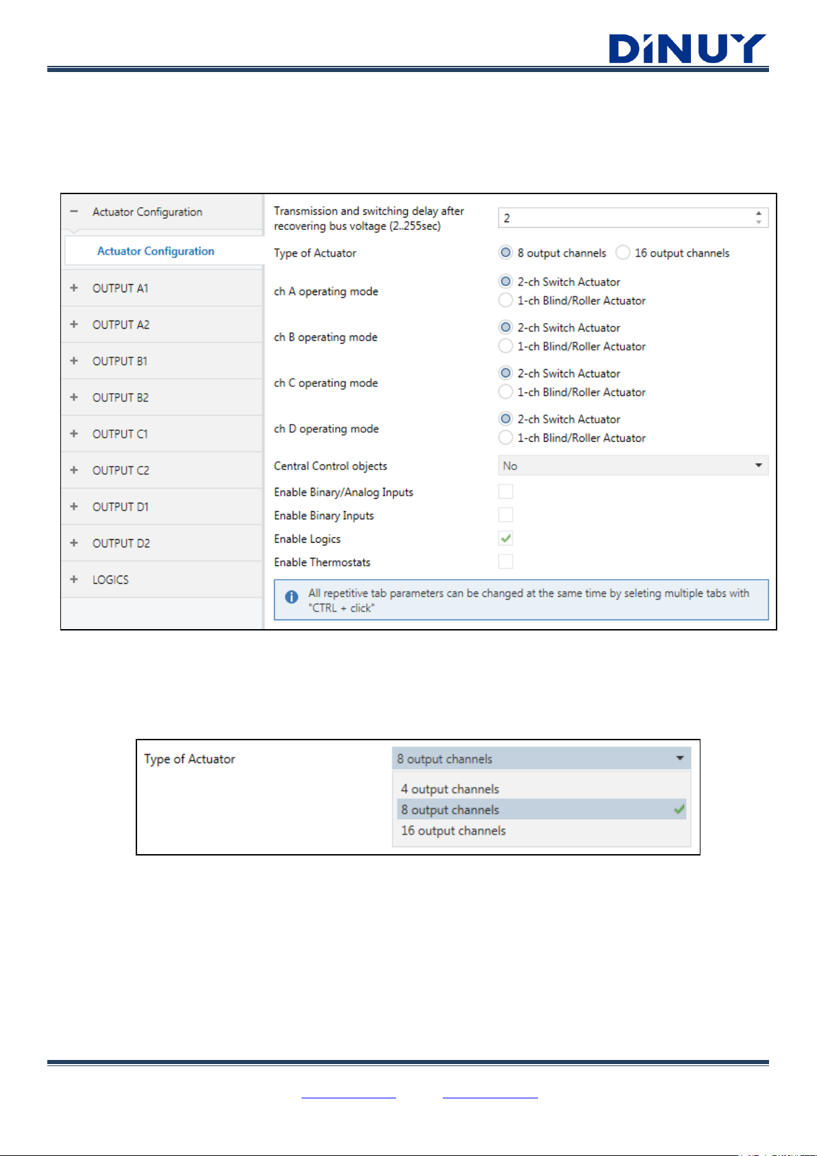
GENERAL Configuration
An initial screen is available where it is possible to configure each channel of the Actuator for the control of 1 Blind or 2
Switching channels:
· Transmission and switching delay after recovering bus voltage (0..255sec): Sets the delay time for sending the
switching telegram after bus voltage is restored.
· Type of Actuator: Allows selecting the Actuator which is going to be parameterized: IT KNT 004 – 4 channels, IT KNT
008 – 8 channels or IT KNT 016 – 16 channels.
· ch A..D operating mode: Configures each pair of complementary channels as independent switching channels or as a blind
channel.
DINUY S.A. c/Auzolan 2, 20303 Irun (Spain)
Tel.: +34943627988 – E-mail: knx@dinuy.com – Web: www.dinuy.com 5
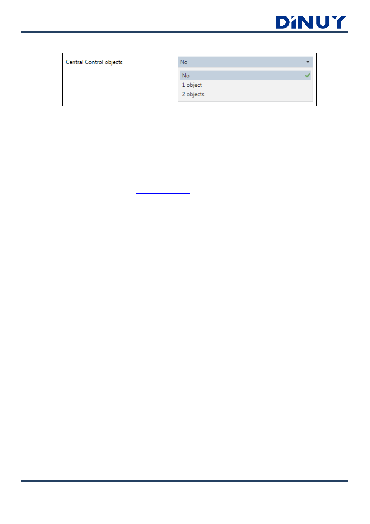
· Central Control objects: It allows a centralized control of each channel if it has been enabled.
· No: centralized control is not enabled.
· 1 object: an object, "[Central] Switch / Move Blind", is enabled for the control of all enabled channels.
· 2 objects: Two objects are enabled. One for the control of the enabled switching channels, "[Central] Switch",
and the other for the control of the enabled blind channels, "[Central] Move Blind".
· Enable Binary/Analog Inputs: allows enabling the Binary/Analog Inputs of the Actuator:
· IT KNT 008: 4 Binary/Analog Inputs.
· IT KNT 016: 7 Binary/Analog Inputs.
For its configuration, see the document: “Inputs – User Manual”
· Enable Binary Inputs: allows enabling the Binary Inputs of the Actuator:
· IT KNT 008: 8 Binary Inputs.
· IT KNT 016: 16 Binary Inputs.
For its configuration, see the document: “Inputs – User Manual”
· Enable Logics: allows enabling the logic functions module:
· IT KNT 008: 8 Logic Functions.
· IT KNT 016: 16 Logic Functions.
For its configuration, see the document: “Logics – User Manual”
· Enable Thermostats: allows enabling the Heating or Cooling Thermostat module:
· IT KNT 008: 4 Thermostats.
· IT KNT 016: 7 Thermostats.
For its configuration, see the document: “Thermostat – User Manual”
DINUY S.A. c/Auzolan 2, 20303 Irun (Spain)
Tel.: +34943627988 – E-mail: knx@dinuy.com – Web: www.dinuy.com 6
OUTPUTS Configuration
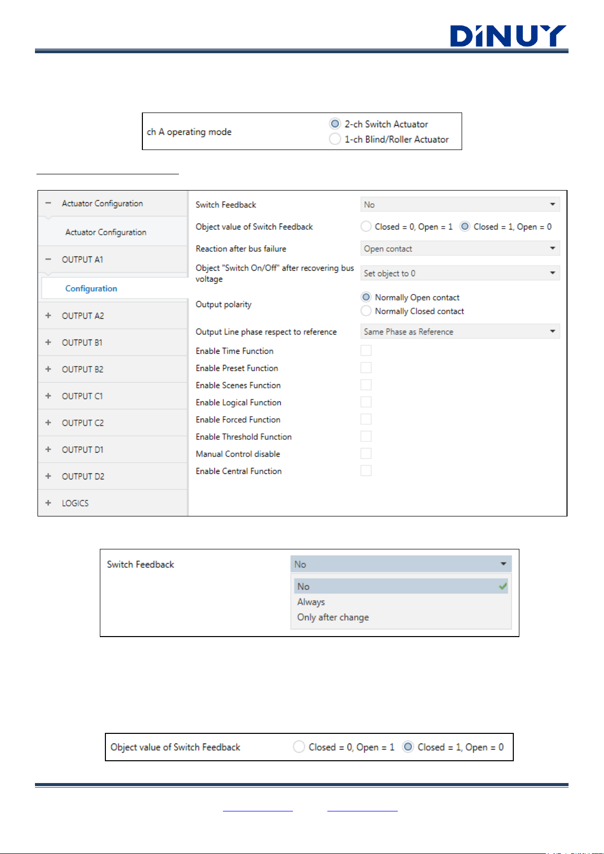
Each channel can be configured for the control of 2 independent loads or 1 single blind:
Switch Channel Configuration
· Switch Feedback: Enables the object “[Out] Switch Feedback” which reports the On/Off status of the channel.
· No: “[Out] Switch Feedback” object is not available.
· Always: “[Out] Switch Feedback” object is always sent, whether or not there is a change in the state of the
channel.
· Only after change: “[Out] Switch Feedback” object is sent when changes the status of the channel.
· Object value of Switch Feedback: Sets the polarity of “[Out] Switch Feedback” object.
DINUY S.A. c/Auzolan 2, 20303 Irun (Spain)
Tel.: +34943627988 – E-mail: knx@dinuy.com – Web: www.dinuy.com 7
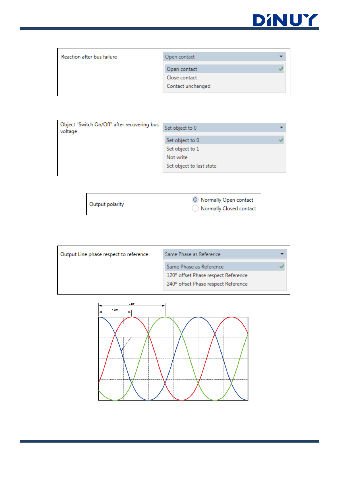
· Reaction after bus failure: Determines the behavior of the channel when the bus voltage is restored.
· Object “Switch On/Off” after recovering bus voltage: Sets the behavior of the channel, through the “[Out] Switch
On/Off” object, after recovering bus voltage.
· Output polarity: Determines the polarity of the output channel.
· Output Line phase respect to reference: Allows the "zero-crossing-point" switching control of the relay. This type of
control makes it possible to switch high loads without risk of damaging the relay due to the high current peaks of the load at
starting. The Reference Phase is that with which the Actuator is supply in L and N.
· Enable Time Function: Enables timing features.
Reference
Phase
DINUY S.A. c/Auzolan 2, 20303 Irun (Spain)
Tel.: +34943627988 – E-mail: knx@dinuy.com – Web: www.dinuy.com 8
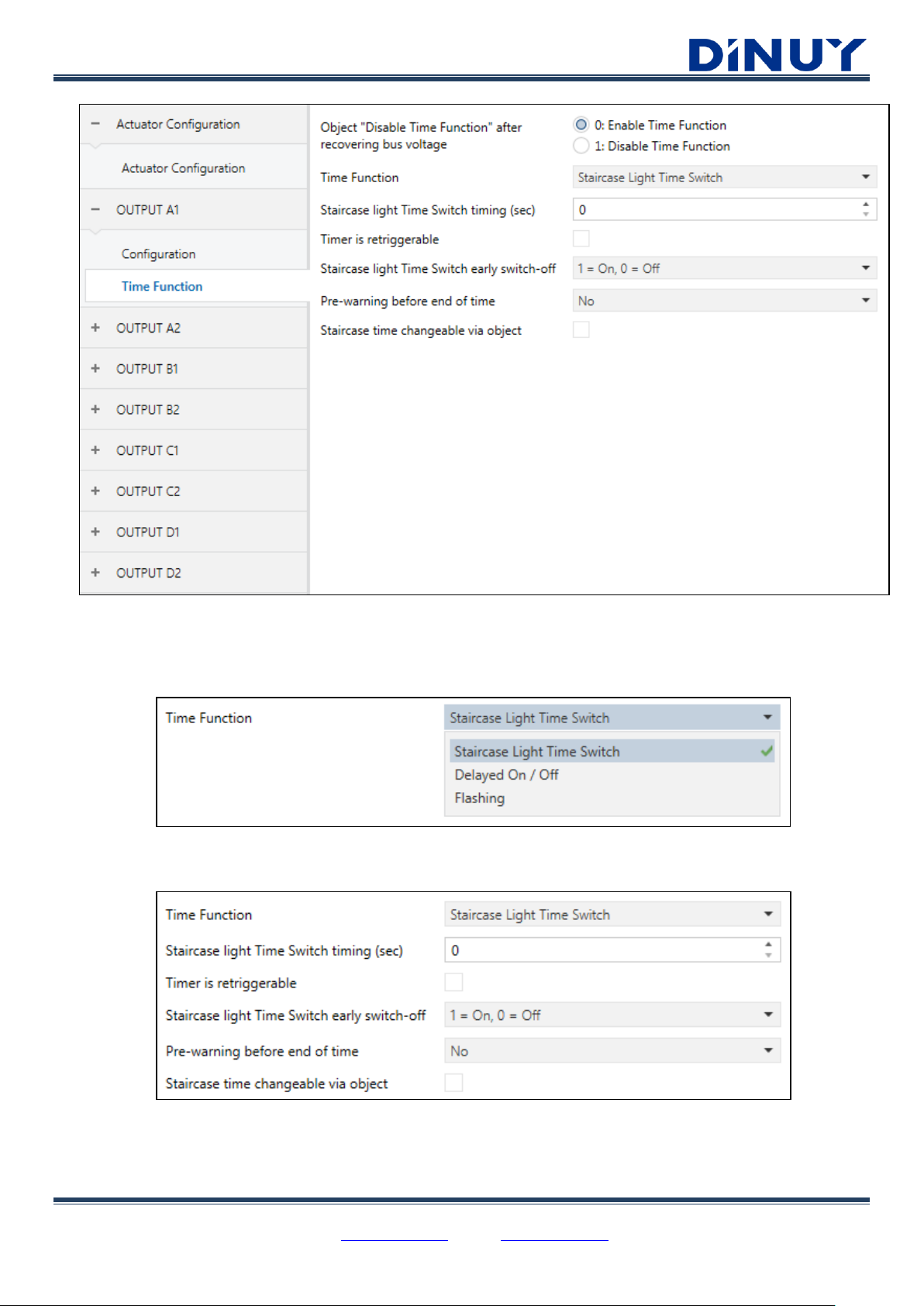
· Object “Disable Time Function” after recovering bus voltage: defines the value of the object “[Out] Disable Time
Function” when bus voltage is restored. The timing functions may return Enabled (0) or Disabled (1).
· Time Function: actuator behavior as a timer.
▪ Staircase Light Time Switch: timing function in which the output is activated through a 1-bit object, “[Out]
Time Switch”, and deactivated after a set time.
· Staircase light Time Switch timing (sec): between 0 and 65535 seconds.
· Timer is retriggerable: allows resetting the set time and start the timing again.
· Staircase Time Switch early switch-off:

DINUY S.A. c/Auzolan 2, 20303 Irun (Spain)
Tel.: +34943627988 – E-mail: knx@dinuy.com – Web: www.dinuy.com 9
· Pre-warning before end of time:
· Pre-warning time (sec): between 0 and 65535 seconds.
· Staircase time changeable via object: enables a 2-byte object, "[Out] Staircase Time (sec)", which allows
setting the timing through the bus.
▪ Delayed On / Off: allows to turn on and off with a delay time.
▪ Flashing: flashing with an On time and Off time.
· Enable Preset Function: enables two 1-bit objects which allow saving, “[Out] Set Preset ½”, or recover, “[Out] Call
Preset ½”, a previous set action.
· Enables Scenes Function: allows to save and recover up to 5 different Scenes.

DINUY S.A. c/Auzolan 2, 20303 Irun (Spain)
Tel.: +34943627988 – E-mail: knx@dinuy.com – Web: www.dinuy.com 10
· Enable Logical Function: allows to enable up to 2 different logical functions. The logic gate can be: AND, OR or XOR.
· Enable Forced Function: enables the Forced function. Its priority is higher than the standard telegrams. It is possible
to enable a 1-bit or 2-bit object, “[Out] Forced”.
· Enable Threshold Function: a threshold value of 1 or 2 bytes is established, and pre-established actions are carried
out based on 2 set values.

DINUY S.A. c/Auzolan 2, 20303 Irun (Spain)
Tel.: +34943627988 – E-mail: knx@dinuy.com – Web: www.dinuy.com 11
· Manual Control disable: allows enabling/disabling the manual control of the channel from the front keypad of the
Actuator.
· Enable Central Function: Includes or not the channel in the centralized control. The control object for the channels
configured as Switch is “[Central] Switch / Move Blind”. Depending on the configuration of the channel, as well as the
number of objects enabled for centralized control, the possible actions will be different.
· No reaction: the channel will not be included in the centralized control.
· Any value = On: any value received on the “[Central] Switch” object will activate the channel.
· Any value = Off: any value received on the “[Central] Switch” object will deactivate the channel.
· 0 = Off, 1 = On: if a 0 is received in the “[Central] Switch” object, the channel will be switched off, while if a 1
is received, the channel will be switched on.
· 0 = On, 1 = Off: if a 0 is received in the “[Central] Switch” object, the channel will be switched on, while if a 1
is received, the channel will be switched off.
· 0 = No reaction, 1 = On: if a 0 is received in the “[Central] Switch” object, the channel will do nothing, while
if a 1 is received, the channel will be switched on.
· 0 = Off, 1 = No reaction: if a 0 is received on the “[Central] Switch” object, the channel will be switched off,
while if a 1 is received, the channel will not react.

DINUY S.A. c/Auzolan 2, 20303 Irun (Spain)
Tel.: +34943627988 – E-mail: knx@dinuy.com – Web: www.dinuy.com 12
Blind Channel Configuration
· Type of Device: Sets the operating mode of the channel.
· Venetian Blind (blinds or blinds with slats):

DINUY S.A. c/Auzolan 2, 20303 Irun (Spain)
Tel.: +34943627988 – E-mail: knx@dinuy.com – Web: www.dinuy.com 13
· Roller Shutter/Awning:
· Venting Louver:
General Parameters
- Regardless of the selected configuration, there are some common parameters by default:
· Behavior after recovering bus voltage: action when the KNX bus voltage is restored.
· Louver / Blind / Roller Movement time (sec): set the movement time from when the louver/blind/roller is fully
raised (position = 0%) until it moves completely down (position = 100%), and vice versa. This time can be set between 1
and 3600 seconds.

DINUY S.A. c/Auzolan 2, 20303 Irun (Spain)
Tel.: +34943627988 – E-mail: knx@dinuy.com – Web: www.dinuy.com 14
· Slats Movement time (only Venetian blind): establishes the total time of movement of the slats from when they are
completely open (position = 0%) until they close completely (position = 100%), and vice versa. This time can be set
between 2 and 600 tenths of a second. The number of steps of the slats will be calculated by dividing this time between
the duration of the step, established in the general parameters.
· Fabric tensioning time (only Roller shutter/Awning): establishes a time of tension of the fabric when the awning is
lowered completely (100%) to avoid that the same one is damaged. It is a rising movement.
· Reaction after bus failure: shutter behavior after a KNX bus fault detected.
· Extra time for Up movement (%): time added to the moving-up to complete the movement. Due to the weight of
the blind, it may take longer to move up than down.
· Reversion Pause time (msec): extra time that the blind is paused when changing the direction of movement.
· Step operation possible: sets if the Step action, or only Stop, is allowed through the object “[BL] Stop / Step
Up/Down”.
· Output Line pase respect to reference: allows to control the "zero crossing" in the relay switching of the
corresponding channel. This type of control makes it possible to switch high loads without damaging the relay contacts
due to the high current peaks of the load at the starting. The Reference Phase is that with which the Actuator is supplied
in L and N.
Advanced Parameters
- Furthermore, in both operating configurations several advanced functions are available:
Reference
Phase

DINUY S.A. c/Auzolan 2, 20303 Irun (Spain)
Tel.: +34943627988 – E-mail: knx@dinuy.com – Web: www.dinuy.com 15
· Enable object: Blind/Roller/Louver position Feedback (%): allows knowing the position of the blind through the 1-
byte object, "[BL] Blind/Roller/Louver position Feedback". When this object is enabled, it will be necessary to set the
period for sending it: "Time to send "Current position" (sec)". This time can be set between 60 and 3600 seconds.
· Enable object: Slats position Feedback (%): allows knowing the position of the slats through the 1-byte object,
“[BL] Slats position Feedback”. When this object is enabled, it will be necessary to set the sending cycle: "Time to send
"Slats position" (sec)". This time can be set between 60 and 3600 seconds.
· Enable object: Movement Feedback: reports the direction of movement of the blind through the 1-bit object, “[BL]
Movement Feedback”.
· Enable Weather Alarms: enables Wind, Rain and Frost Alarms. These alarms prevail over all other functions.

DINUY S.A. c/Auzolan 2, 20303 Irun (Spain)
Tel.: +34943627988 – E-mail: knx@dinuy.com – Web: www.dinuy.com 16
o Wind Alarms: up to 3 wind alarms can be enabled.
▪ Enable object: Wind Alarm 1..2: allows enabling wind alarm control and its watchdog time.
▪ Behavior when starting Wind Alarm: establishes the behavior of the blind when an alarm situation
occurs in one of the 3 objects. The different options are: No action, Up, Down or Stop.
▪ Behavior when starting finishing Alarm: sets the behavior of the blind at the end of the wind alarm.
The different options are: No action, Up, Down, Stop or Go to last position.
o Rain Alarm: 1 rain alarm can be enabled.

DINUY S.A. c/Auzolan 2, 20303 Irun (Spain)
Tel.: +34943627988 – E-mail: knx@dinuy.com – Web: www.dinuy.com 17
▪ Enable Rain Alarm Watchdog: allows enabling rain alarm and its watchdog time.
▪ Behavior when starting Rain Alarm: establishes the behavior of the blind when an alarm situation
occurs in one of the 3 objects. The different options are: No action, Up, Down or Stop.
▪ Behavior when finishing Rain Alarm: sets the behavior of the blind at the end of the wind alarm. The
different options are: No action, Up, Down, Stop or Go to last position.
o Frost Alarm: 1 frost alarm can be enabled.
▪ Enable Frost Alarm Watchdog: allows enabling frost alarm and its watchdog time.
▪ Behavior when starting Frost Alarm: establishes the behavior of the blind when an alarm situation
occurs in one of the 3 objects. The different options are: No action, Up, Down or Stop.
▪ Behavior when finishing Frost Alarm: sets the behavior of the blind at the end of the wind alarm. The
different options are: No action, Up, Down, Stop or Go to last position.
o Alarms priority: sets the priority level of the different alarms.
▪ Weather Alarms priority: defines the hierarchy of priorities between the different alarms.
▪ Forced vs Weather Alarm Prority: sets the priority between weather alarms and forced action.
· Enable Sun Protection: function that allows protection from the sun inside the room.

DINUY S.A. c/Auzolan 2, 20303 Irun (Spain)
Tel.: +34943627988 – E-mail: knx@dinuy.com – Web: www.dinuy.com 18
o Type of Protection object: allows setting the protection according to 1-bit object or the Lux value received
from a brightness sensor.
▪ 1-Bit On/Off object: enables a 1-bit input object for the sun protection function, “[BL] Sun Protection
Input”. In this case, it is necessary to define:
• Sun Protection object polarity: 0 or 1, which will trigger the protection.
• Delay time to Start Sun Protection: 1 ~ 3600 seconds.
• Behavior when starting Sun Protection: No action, Up, Down, Stop, Call Scene, Go to
position or variable via position object (activate the object “[BL] Sun Protection position
Input”.
• Delay time to Finish Sun Protection (sec): 1 ~ 3600 seconds.
• Behavior when finishing Sun Protection: No action, Up, Down or Go to the last position.
▪ Lux level value object: enables a 2-byte input object for the sun protection function, “[BL] Lux level
Input”. In this case, it is necessary to define:
• Lux value to Start Protection: 1 ~ 3600 Lux.
• Lux value to Finish Protection: 1 ~ 3600 Lux.
• Delay time to Start Sun Protection (sec): 1 ~ 3600 seconds.
• Behavior when starting Sun Protection: No action, Up, Down, Stop, Call Scene, Go to
position or Variable via position object (activate the object “[BL] Sun Protection position
Input”.
• Delay time to Finish Sun Protection (sec): 1 ~ 3600 seconds.
• Behavior when finishing Sun Protection: No action, Up, Down or Go to previous position.

DINUY S.A. c/Auzolan 2, 20303 Irun (Spain)
Tel.: +34943627988 – E-mail: knx@dinuy.com – Web: www.dinuy.com 19
· Enable Scenes Function: allows to preset up to 8 different Scenes. In each Scene the position of the Blind and the
position of the Slats must be set.
· Forced state after recovering bus voltage: enables the Forced function. Its priority is higher than standard operating
orders and it can be defined, or not, over alarms, in the Alarms window.
· Manual Control disable: enable, or not, the manual control of the actuator from the front keypad of the device.
· Disable relay switching with zero-cross control: in case of controlling the slats of the blind, it will be necessary to
activate this parameter to achieve optimal results in the movement of the same.
· Enable Central Function: establishes the behavior of the blind in case of receiving a telegram from the Central
Function. The control object for the channels configured as Blind is "[Central] Switch / Move Blind" or "[Central] Move
Blind", depending on the number of objects enabled for centralized control (1 or 2).
• No reaction: the channel does not respond to centralized orders.
• Any value = Up: any value received in the object "[Central] Move Blind" will produce a moving-up of the
blind connected to this channel.
• Any value = Down: any value received in the object "[Central] Move Blind" will produce a moving-down
of the blind connected to this channel.
• Any value = Position: any value received in the object "[Central] Move Blind" will cause a movement of
the blind connected to this channel to the set value.
• 0 = Up, 1 = Down: a 0 received in the object “[Central] Move Blind” will produce a moving-up of the
blind connected to this channel, and a 1 will cause a moving-down.
• 1 = Up, 0 = Down: : a 1 received in the object “[Central] Move Blind” will produce a moving-up of the
blind connected to this channel, and a 0 will cause a moving-down.

DINUY S.A. c/Auzolan 2, 20303 Irun (Spain)
Tel.: +34943627988 – E-mail: knx@dinuy.com – Web: www.dinuy.com 20
• 0 = No reaction, 1 = Down: a 0 received in the object “[Central] Move Blind” will not produce any action
on the blind connected to this channel, and a 1 will produce a moving-down.
• 0 = Up, 1 = No reaction: a 1 received in the object “[Central] Move Blind” will not produce any action on
the blind connected to this channel, and a 0 will produce a moving-down.

DINUY S.A. c/Auzolan 2, 20303 Irun (Spain)
Tel.: +34943627988 – E-mail: knx@dinuy.com – Web: www.dinuy.com 21
Communication Objects
Central Function Objects
Number
Name
Function
Description
1
[Central] Switch
On/Off
Central control object for channels configured as Switches or
for channels configured as Blind, in case of enabling a single
control object
2
[Central] Move Blind
Up / Down / Position
Central control object for channels configured as Blind, if two
control objects are enabled

DINUY S.A. c/Auzolan 2, 20303 Irun (Spain)
Tel.: +34943627988 – E-mail: knx@dinuy.com – Web: www.dinuy.com 22
Switch Channel Objects
Number
Name
Function
Description
19
[Out] Switch Feedback
1 = On, 0 = Off
Feedback object of the status of the channel
20
[Out] Switch On/Off
1 = On, 0 = Off
Input object to switch the channel
21
[Out] Permanent ON
1 = On, 0 = Off
Input object to perform permanent channel switching in the Time
Function, ignoring the established timing
22
[Out] Disable Time Function
1 = Disable, 0 = Enable
Enable or not the Time Function
23
[Out] Change Threshold 1
1 Byte value
Input object that allows to change the Threshold 1 value of the
Threshold Function via the Bus

DINUY S.A. c/Auzolan 2, 20303 Irun (Spain)
Tel.: +34943627988 – E-mail: knx@dinuy.com – Web: www.dinuy.com 23
24
[Out] Threshold Input
1 Byte value
Input value that is taken as the set-point of the Threshold
function
25
[Out] Forced 1 Bit
[Out] Forced 2 Bits
1 = Forced, 0 = Not Forced
2 Bits value
Forced Order, with priority higher than standard operation. In
case of selecting a 2-bit type, one of the bits indicates if the Force
is active (yes/no) and with the second bit it is indicated if the
force is On or Off
26
[Out] Logical connection 1
1 = True, 0 = False
Logical connection 1
27
[Out] Logical connection 2
1 = True, 0 = False
Logical connection 2
28
[Out] Scene
Scene Control
1-Byte object for Scenes management
29
[Out] Set Preset ½
Telegram 0 → Set Preset 1
Telegram 1 → Set Preset 2
If this object is at “0”, the value of Preset 1 is set, if not, Preset 2
30
[Out] Call Preset ½
Telegram 0 → Call Preset 1
Telegram 1 → Call Preset 2
If this object is “0”, Preset 1 is set to output, if not, Preset 2
31
[Out] Staircase lighting Pre-warning
1 = Pre-warning, 0 = No Pre-warning
Enable or not the pre-warning before the end of the timing
32
[Out] Staircase Time (sec)
2 Bytes value
It allows setting the timing through the Bus
33
[Out] Time Switch
1 = Timer On
Input object to start the previously set timing function

DINUY S.A. c/Auzolan 2, 20303 Irun (Spain)
Tel.: +34943627988 – E-mail: knx@dinuy.com – Web: www.dinuy.com 24
Blind Channel Objects
Number
Name
Function
Description
244
[BL] Blind Move Up/Down
0 = Up, 1 = Down
A 0 on this object will move-up the blind, whereas a 1 will move-
down the blind
245
[BL] Blind Stop / Step Up/Down
0 = Step Up, 0 = Step Down
A 0 on this object will stop the blind or make a step-up (if
enabled). A 1 on this object will stop the blind or make a step-
down (if enabled)
246
[BL] Forced Input
2 Bits control
Forced order, with priority higher than standard operation. One
of the bits indicates if the Force is active (yes/no) and with the
second bit it is indicated if the Force is On or Off

DINUY S.A. c/Auzolan 2, 20303 Irun (Spain)
Tel.: +34943627988 – E-mail: knx@dinuy.com – Web: www.dinuy.com 25
247
[BL] Wind Alarm 1
1 = Alarm, 0 = No Alarm
Wind alarm input object
248
[BL] Wind Alarm 2
1 = Alarm, 0 = No Alarm
Wind alarm input object
249
[BL] Wind Alarm 3
1 = Alarm, 0 = No Alarm
Wind alarm input object
250
[BL] Rain Alarm
1 = Alarm, 0 = No Alarm
Rain alarm input object
251
[BL] Frost Alarm
1 = Alarm, 0 = No Alarm
Frost alarm input object
252
[BL] Scene Input
Scene Control
1-byte object for Scenes control
253
[BL] Movement Feedback
0 = Up, 1 = Down
Information object of the movement of the blind
254
[BL] Blind position Input
0% = Open, 100% = Closed
The blind moves to the received position (%) through this 1-byte
value
255
[BL] Slats position Input
0% = Open, 100% = Closed
The slats move to the received position (%) through this 1-byte
value
256
[BL] Blind position Feedback
0% = Open, 100% = Closed
Information object of the position of the blind
257
[BL] Slats position Feedback
0% = Open, 100% = Closed
Information object of the position of the slats
258
[BL] Sun Protection Input
1 = On, 0 = Off
Sun Protection input object
259
[BL] Sun Protection position Input
0% = Open, 100% = Closed
Sun Protection position input object
 Loading...