

Page 1

MTG3000 VoIP Trunk Gateway
User Manual v1.0
Dinstar Technologies Co., Ltd.
Address: 9th Floor, Guoxing Building, Changxing Road, Nanshan District, Shenzhen, China
Postal Code: 518052
Telephone: +86 755 61919966
Fax: +86 755 2645 6659
Emails: [email protected], [email protected]
Website: www.dinstar.com
Page 2

Welcome
Thanks for choosing MTG3000 Trunk Gateway! We hope you will make optimum use of this flexible,
rich-feature trunk gateway. Please read this document carefully before install the gateway.
About this manual
This manual provides information about the introduction of the gateway and about how to install, configure
or use the gateway.
This manual is written with reference to the default configurations of the MTG3000 Trunk Gateway.
Intended audience
This manual is aimed primarily at network and system engineers who will install, configure and maintain
the gateway.
System engineers are persons who customize the configurations to meet the requirements of users.
Parts of this document are aimed at users who will actually use the gateway.
Revision Records
Document Name
MTG3000 Trunk Gateway User Manual v1.0
Document version
V1.0
Firmware version
2.05.03.03
Revised by
Ivanka Yuan
Date
March 3, 2016
Page 3

Table of Contents
1 Product Description ..................................................................................................................................... 1
1.1 Overview ..................................................................................................................................................... 1
1.2 Application Scenario ................................................................................................................................. 1
1.3 Product Appearance .................................................................................................................................. 2
1.3.1 Image of MTG3000 .................................................................................................................................. 2
1.3.2 Image of MCU and DTU ......................................................................................................................... 2
1.3.3 Description of Ports and Indicators .......................................................................................................... 3
1.4 Functions and Features ............................................................................................................................. 5
1.4.1 Key Features ............................................................................................................................................. 5
1.4.2 Protocols Supported ................................................................................................................................. 5
1.4.3 Physical Interfaces .................................................................................................................................... 5
1.4.4 System Functions ..................................................................................................................................... 6
1.4.5 Software Features ..................................................................................................................................... 6
1.4.6 Call Features ............................................................................................................................................. 7
1.4.7 Hardware Specifications & Environment ................................................................................................ 7
2 Quick Installation ......................................................................................................................................... 8
2.1 Preparations before Installation .............................................................................................................. 8
2.1.1 Attentions for Installation ......................................................................................................................... 8
2.1.2 Preparations about Installation Site .......................................................................................................... 8
2.1.3 Installation Tools ...................................................................................................................................... 8
2.1.4 Unpacking................................................................................................................................................. 9
2.2 Installation of MTG3000 .......................................................................................................................... 9
2.2.1 Put MTG3000 into Shelf .......................................................................................................................... 9
2.2.2 Connect Ground Wire to MTG3000 ........................................................................................................ 9
2.2.3 Connect MTG3000 to Network ............................................................................................................... 9
2.2.4 Connect MTG3000 to PSTN .................................................................................................................. 10
2.3 Troubleshooting ....................................................................................................................................... 10
3 Basic Operation .......................................................................................................................................... 11
3.1 Configuration of IP Address ................................................................................................................... 11
3.2 Local Maintenance .................................................................................................................................. 11
3.2.1 Example: Log in MTG3000 via Console Port ....................................................................................... 12
3.3 Query IP ................................................................................................................................................... 14
Page 4

4 Configurations on Web Interface ............................................................................................................. 15
4.1 How to Log in Web Interface ................................................................................................................. 15
4.1.1 Network Connection .............................................................................................................................. 15
4.1.2 Preparations for Login ............................................................................................................................ 15
4.1.3 Log in Web Interface .............................................................................................................................. 15
4.2 Introduction to Web Interface ............................................................................................................... 16
4.3 Configuration Flows ................................................................................................................................ 17
4.4 Status & Statistics .................................................................................................................................... 17
4.4.1 System Information ................................................................................................................................ 17
4.4.2 E1/T1 Status ........................................................................................................................................... 18
4.4.3 PSTN Trunk Status ................................................................................................................................. 20
4.4.4 IP Trunk Status ....................................................................................................................................... 20
4.4.5 PRI Call Statistics ................................................................................................................................... 21
4.4.6 SS7 Call Statistics .................................................................................................................................. 21
4.4.7 SIP Call Statistics ................................................................................................................................... 22
4.4.8 Radius Statistics ..................................................................................................................................... 23
4.4.9 Record Statistics ..................................................................................................................................... 23
4.5 Network .................................................................................................................................................... 23
4.6 SDH Config .............................................................................................................................................. 24
4.6.1 SDH Param ............................................................................................................................................. 25
4.6.2 SDH Alarm ............................................................................................................................................. 26
4.6.3 Channel Map .......................................................................................................................................... 27
4.7 PRI Config ................................................................................................................................................ 28
4.7.1 PRI Parameter......................................................................................................................................... 28
4.7.2 PRI Trunk ............................................................................................................................................... 29
4.8 SS7 Config ................................................................................................................................................ 30
4.8.1 SS7 Parameter ........................................................................................................................................ 30
4.8.2 Create SS7 Trunks .................................................................................................................................. 30
4.8.3 SS7 MTP Link ........................................................................................................................................ 31
4.8.4 SS7 CIC .................................................................................................................................................. 32
4.8.5 SS7 CIC Maintain .................................................................................................................................. 34
4.9 PSTN Group Config ................................................................................................................................ 36
4.9.1 Clock Source .......................................................................................................................................... 36
4.9.2 E1/T1 Parameter ..................................................................................................................................... 37
4.9.3 Codec Group........................................................................................................................................... 38
4.9.4 Dial Plan ................................................................................................................................................. 40
4.9.5 Dial Timeout ........................................................................................................................................... 41
Page 5

4.9.6 PSTN Profile .......................................................................................................................................... 42
4.9.7 PSTN Group ........................................................................................................................................... 43
4.9.8 PSTN Group Management ..................................................................................................................... 44
4.10 SIP Config .............................................................................................................................................. 45
4.10.1 SIP Parameter ....................................................................................................................................... 45
4.10.2 SIP Trunk .............................................................................................................................................. 46
4.11 IP Group Config ..................................................................................................................................... 50
4.11.1 IP Profile ............................................................................................................................................... 50
4.11.2 IP Group ................................................................................................................................................ 52
4.11.3 IP Group Management ......................................................................................................................... 52
4.12 Number Filter ........................................................................................................................................ 53
4.12.1 Procedures to add a number on the Caller White List ......................................................................... 54
4.12.2 Caller Pool ............................................................................................................................................ 55
4.12.3 Filter Profile ......................................................................................................................................... 55
4.13 Call Routing ........................................................................................................................................... 56
4.13.1 Routing Parameter ................................................................................................................................ 56
4.13.2 PSTNIP Routing ............................................................................................................................... 57
4.13.3 PSTN PSTN Routing ...................................................................................................................... 58
4.13.4 IP PSTN Routing ............................................................................................................................. 59
4.13.5 IP IP Routing .................................................................................................................................... 61
4.14 Number Manipulation .......................................................................................................................... 62
4.14.1 PSTN IP Callee ................................................................................................................................ 62
4.14.2 PSTNIP Caller .................................................................................................................................. 63
4.14.3 PSTNPSTN Callee ........................................................................................................................... 65
4.14.4 PSTN PSTN Caller ........................................................................................................................... 66
4.14.5 IPPSTN Callee ................................................................................................................................. 68
4.14.6 IPPSTN Caller .................................................................................................................................. 69
4.14.7 IP IP Callee ...................................................................................................................................... 71
4.14.8 IP IP Caller ...................................................................................................................................... 72
4.15 Voice & Fax ............................................................................................................................................ 74
4.16 Encrypt Config ...................................................................................................................................... 76
4.17 Maintenance ........................................................................................................................................... 77
4.17.1 Management Parameter ........................................................................................................................ 77
4.17.2 Data Backup ......................................................................................................................................... 78
4.17.3 Data Restore ......................................................................................................................................... 78
4.17.4 Network Capture .................................................................................................................................. 78
4.17.5 Signaling Call Test ............................................................................................................................... 79
Page 6

4.17.6 ModFile Information ............................................................................................................................ 80
4.17.7 Version Information .............................................................................................................................. 80
4.17.8 Firmware Upgrade ................................................................................................................................ 81
4.17.9 Password Modification ......................................................................................................................... 81
4.17.10 Device Restart .................................................................................................................................... 82
5 Abbreviation ................................................................................................................................................ 83
6 Commands................................................................................................................................................... 84
6.1 Commands under en Mode .................................................................................................................... 84
6.1.1 Login Command ..................................................................................................................................... 84
6.1.2 Query IP Address .................................................................................................................................... 84
6.1.3 Query Statistics about DTU ................................................................................................................... 84
6.1.4 Query DSP Information.......................................................................................................................... 85
6.1.5 Query CPU Performance ........................................................................................................................ 85
6.1.6 Query SS7 Trunk Status ......................................................................................................................... 86
6.1.7 Query SS7 Link Statistics ...................................................................................................................... 86
6.1.8 Query SS7 Call Statistics ....................................................................................................................... 86
6.1.9 Query SS7 Errors.................................................................................................................................... 86
6.1.10 Query PRI Trunk Status ....................................................................................................................... 86
6.1.11 Query PRI Link Statistics ..................................................................................................................... 87
6.1.12 Query PRI Call Statistics ..................................................................................................................... 87
6.1.13 Query Packet Statistics of HDLC Channel and Related Error Codes ................................................. 87
6.1.14 Query Status of E1 Port ........................................................................................................................ 87
6.1.15 Query Statistics of All Calls ................................................................................................................. 87
6.2 Commands under config Mode .............................................................................................................. 87
6.2.1 Login Commands ................................................................................................................................... 87
6.2.2 Other Commands .................................................................................................................................... 87
6.3 Commands under ada Mode .................................................................................................................. 88
6.3.1 Login Commands ................................................................................................................................... 88
Page 7
MTG3000 VoIP Trunk Gateway User Manual
1
Copyright @ 2011-2016 Dinstar
1 Product Description
1.1 Overview
MTG3000 is a new-generation intelligent VoIP trunk gateway, featuring high integration and
large-capacity concurrency. Focusing on a concept of maintainable, manageable and operable, it provides
carrier-grade VoIP, FoIP and Modem/POS services, as well as value-added functions such as smart
voice recognition, signal encryption and flexible dialing rules.
MTG3000T supports the conversion of multiple coding methods such as G.711A/U, G.723.1, G.729A/B,
iLBC and AMR. It has good compatibility with Huawei SoftX3000, and other softswitches and IMS
systems from ZTE, Cisco, VOS and Langxun.
Compared to other similar products, MTG3000 has more advantages in terms of performance, system
reliability and compatibility. It is widely used by call centers, operators and large-size enterprises for the
entry into IMS network based on VoIP.
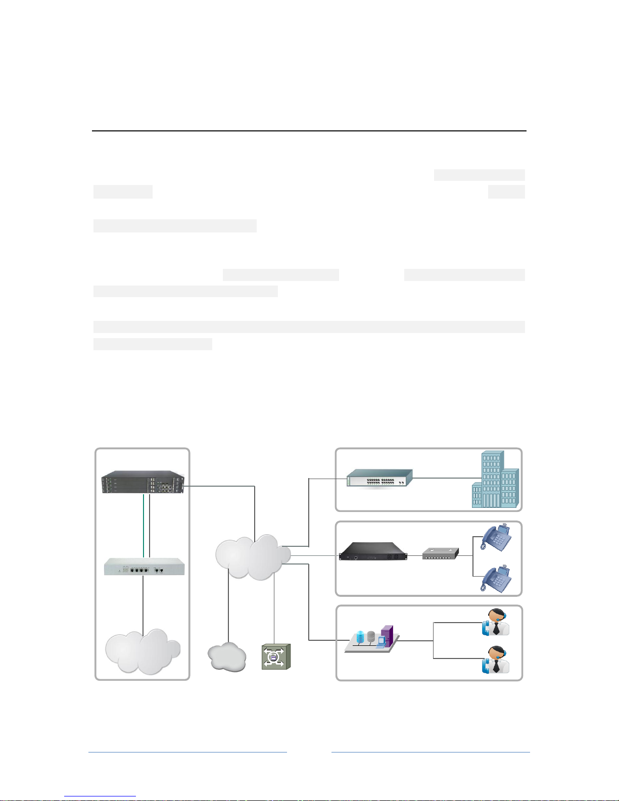
1.2 Application Scenario
The application scenario of MTG3000 VoIP trunk gateway is shown as follows:
Internet
Optical Transceiver
Telephone
Receptionist
MTG3000
IPPBX
PSTN
Call Center
PBX
Enterprise
MTG1000
Softswitch
DMCloud
SDH
E1/T1
PRI/SS7
SIP
Users
Page 8
MTG3000 VoIP Trunk Gateway User Manual
2
Copyright @ 2011-2016 Dinstar
1.3 Product Appearance
1.3.1 Image of MTG3000
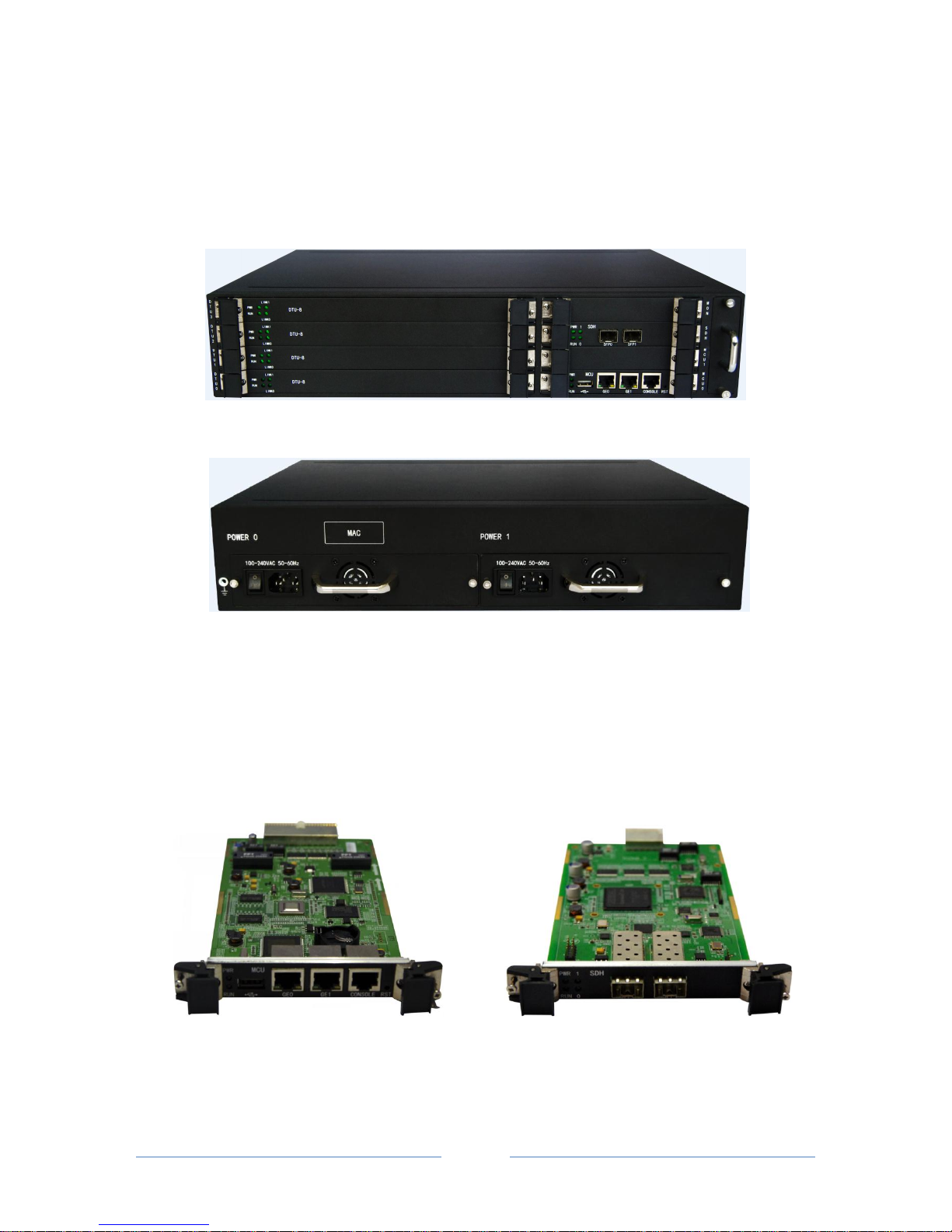
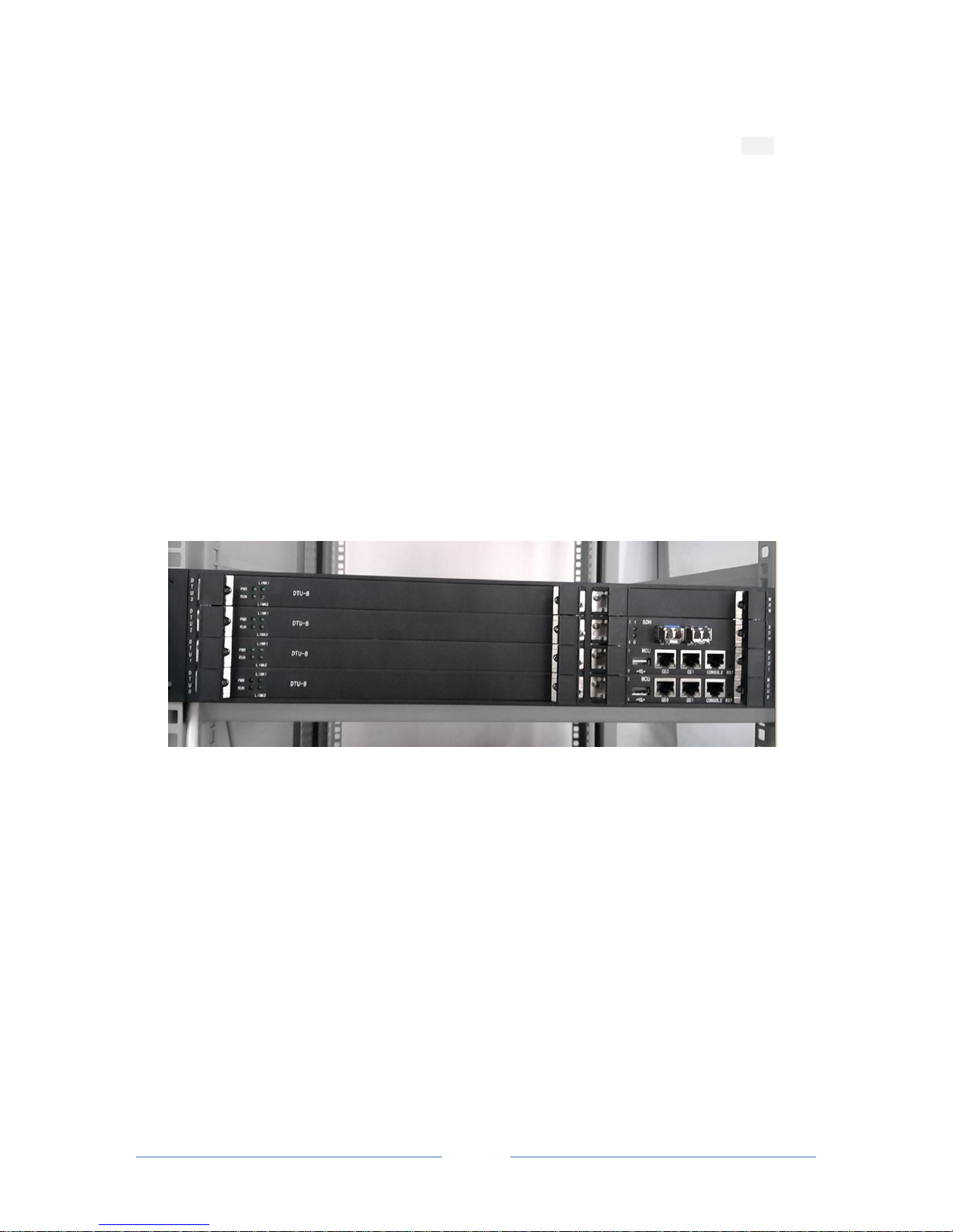
MTG3000 is equipped with four DTU boards, one MCU board, one SDH board and double power supply.
Front View
Back View
1.3.2 Image of MCU and DTU
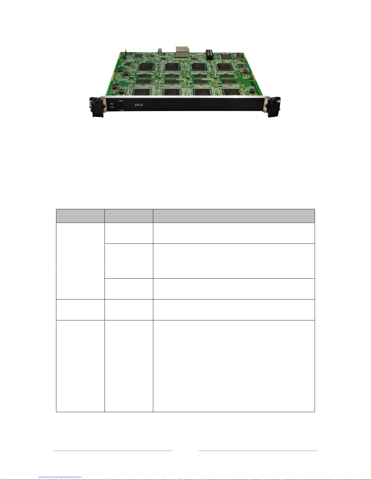
MTG3000 allows users to insert or pull out DTU boards when it is still powered on, and it can
automatically identify the DTU boards that have been inserted. When a DTU board is inserted or pulled out,
users need to re-configure the MTG3000 device.
MCU (Main Control Unit) SDH
Page 9
MTG3000 VoIP Trunk Gateway User Manual
3
Copyright @ 2011-2016 Dinstar
DTU (Digit Trunk Unit)
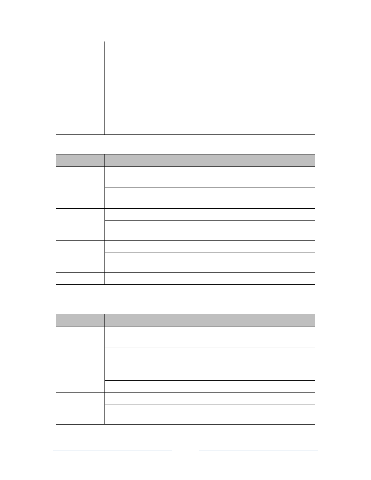
1.3.3 Description of Ports and Indicators
MTG3000 has four DTU boards marked from 0 to 3. Each board has 16 virtual E1/T1 ports that are
integrated into the SDH port, and there are indicators to show the connection between each DTU board and
the MCU board.
MCU Board:
Indicator/Port
Status
Description
PWR
On
The MCU board has been inserted and connected properly to the
MTG3000 box.
Off
The MCU board is faulty or it is not connected properly to the
MTG3000 box.
RUN
Flash slowly
The MCU board runs normally.
Flash quickly
The MCU board is faulty or it is not connected properly to the
MTG3000 box.
CONSOLE
/
The console port used to carry out maintenance-related
configurations, with a baud rate of 115200bps
GE1
/
The gigabit network port for services, which is used to realize
the data transmission of signal or voice. Its default IP address is
192.168.1.111, and default netmask is 255.255.255.0.
When data is transmitted at a rate of 1000Mbps, the green light
on the left flashes while the orange light on the right is on.
When data is transmitted at a rate of 100Mbps, the green light
on the left flashes while the orange light on the right is off.
Page 10
MTG3000 VoIP Trunk Gateway User Manual
4
Copyright @ 2011-2016 Dinstar
GE0
/
The gigabit network port for network management; its default IP
address is 192.168.11.1, and default netmask is 255.255.255.0.
When data is transmitted at a rate of 1000Mbps, the green light
on the left flashes while the orange light on the right is on.
When data is transmitted at a rate of 100Mbps, the green light
on the left flashes while the orange light on the right is off.
RST
/
The button is used to restart MTG3000
DTU Board:
Indicator/Port
Status
Description
PWR
On
The DTU board has been inserted and connected properly to the
MTG3000 box.
Off
The DTU board is faulty or it is not connected properly to the
MTG3000 box.
RUN
Flash slowly
The DTU board runs normally
Flash quickly
The DTU board is faulty or it is not connected properly to the
MTG3000 box.
Link 0
On
The DTU board is properly connected to the MCU board
Off
The DTU board is not or improperly connected to the MCU
board, or the DTU board is faulty.
Link 1
Reserve
Reserve
SDH Board:
Indicator/Port
Status
Description
PWR
On
The SDH board has been inserted and connected properly to the
MTG3000 box.
Off
The SDH board is faulty or it is not connected properly to the
MTG3000 box.
RUN
Flash slowly
The SDH board runs normally
Flash quickly
The SDH board is improperly connected to the MTG3000 box
Light 0
On
The SFP optical module has been inserted into the SFP port 0.
Off
The SFP optical module has not been yet inserted into the SFP
port 0.
Page 11

MTG3000 VoIP Trunk Gateway User Manual
5
Copyright @ 2011-2016 Dinstar
Light 1
On
The SFP optical module has been inserted into the SFP port 1.
Off
The SFP optical module has not been yet inserted into the SFP port 1.
SFP 0
SFP port where SFP optical module is inserted
SFP 1
SFP port where SFP optical module is inserted
1.4 Functions and Features
1.4.1 Key Features
Carrier-grade hardware design, 1+1 power supply
High-integrated structure, STM-1 155M (63*E1) in 2U size
Support flexible dialing rules and operations, allowing users to customize dialing rules according to
different working environments
Support multiple coding standards: G.711A/U, G.723.1, G.729A/B and iLBC
High compatibility, interoperable with PBX of Avaya, NEC and Alcatel, and also leading soft-switch of
Huawei,Cisco and ZTE etc.
1.4.2 Protocols Supported
SIP v2.0(UDP/TCP), RFC3261, SDP, RTP(RFC2833)
SIP Rport
PRI/SS7 Protocol
RTP/RTCP
Dynamic NAT
SIP Trunk Working Mode: Peer/Access
Hypertext Transfer Protocol (HTTP)
ITU-T G.711A-Law/U-Law, G.723.1, G.729AB, iLBC13k/15k, AMR/AMR-GSM
RFC3262, 3263, 3264, 3265, 3515, 2976, 3311
1.4.3 Physical Interfaces
SDH Interfaces
2* Standard LC SDH, 155M
1+1 Redundancy Channels Protection
Master/Slave Clock Source
Main Control Unit (MCU)
1+1 Redundancy, Hot Plug
Page 12

MTG3000 VoIP Trunk Gateway User Manual
6
Copyright @ 2011-2016 Dinstar
Digital Processing Unit (DTU)
4* DTU Maximum
Support 512 Voice Channels Each Board
Ethernet Interface
GE1: 10/100/1000 BaseT Adaptive Ethernet
GE0: 10/100/1000 BaseT Adaptive Ethernet
Console Port
1* RS232, 115200bps
1.4.4 System Functions
Packet Loss Concealment (PLC)
Voice Activity Detection (VAD)
Comfort Noise Generation (CNG)
Echo Cancellation
Packet Loss Compensation
Silence Suppression
Adaptive Jitter Buffer
Gain Control of Voice and Fax
Support Modem and POS
DTMF Modes: RFC2833, SIP INFO and INBAND
T38/Pass-Through Fax over IP
Configurations via HTTP/Telnet
Upgrade Firmware via TFTP/Web
Recognition of Prompt Tone
1.4.5 Software Features
Local/Transparent Ring Back Tone
Overlapping Dialing
Multiple Dialing Rules
PSTN Group Based on E1 Port or E1 Timeslot
Configuration of IP Trunk Group
Voice Codec Group
Caller/Called Number White List
Caller/Called Number Black List
Access Rule List
IP Trunk Priority
Page 13

MTG3000 VoIP Trunk Gateway User Manual
7
Copyright @ 2011-2016 Dinstar
RTP and Signaling Encryption (VOS RC4)
1.4.6 Call Features
Flexible Route Methods: PSTN–PSTN, PSTN–IP, IP–IP, IP–PSTN
Intelligent Routing Rules
Call Routing Based on Time
Call Routing Based on Prefix of Caller/Called Number
Caller and Called Number Manipulation
1.4.7 Hardware Specifications & Environment
Redundant Power Supply
Power Supply: 100 ~ 240V AC, 50 ~60Hz
Power Consumption: 110W
Operating Temperature. 0 ℃ ~ 45 ℃
Storage Temperature: -20 ℃ ~80 ℃
Humidity: 10%-90%, Non-Condensing
Dimensions (W/D/H): 437×320×88mm (2U)
Unit Weight: 6.5kg
Compliance: CE, FCC
Page 14

MTG3000 VoIP Trunk Gateway User Manual
8
Copyright @ 2011-2016 Dinstar
2 Quick Installation
2.1 Preparations before Installation
2.1.1 Attentions for Installation
The attentions for installing MTG3000 include:
To guarantee MTG3000 works normally and to lengthen the service life of the device, the humidity of
the equipment room where MTG3000 is installed should be maintained at 10%-90% (non-condensing),
and temperature should be 0 ℃ ~ 45 ℃;
Ensure the equipment room is well-ventilated and clean;
Power supply of MTG3000 should be 100 ~ 240V AC, and its socket is a three-pin socket which should
be grounded well;
It’s suggested that personnel who has experience or who has received related training be responsible for
installing and maintaining MTG3000;
Please wear anti-static wrist strap when installing MTG3000;
Please do not hot plug or unplug cables;
It’s advised to adopt uninterruptible power supply.
2.1.2 Preparations about Installation Site
Equipment Cabinet
Ensure the cabinet is well-ventilated and strong enough to bear the weight of MTG3000.
Trunk
Ensure telecom operator has approved to open a trunk.
IP Network
Ensure router under IP network has been prepared, since MTG3000 is connected to the IP network
through the standard 10/100/1000M Ethernet port.
Power Supply
Ensure the socket of MTG3000 is a three-pin socket and power supply is grounded well.
2.1.3 Installation Tools
Screwdriver
ESD wrist strap
Ethernet cables, power wires, telephone wires
Hub, telephone set, fax, and PBX
Terminal (can be a PC which is equipped with hyperterminal simulation software)
Page 15
MTG3000 VoIP Trunk Gateway User Manual
9
Copyright @ 2011-2016 Dinstar
2.1.4 Unpacking
Open the packing container to check whether the MTG3000 device and all accessories have been in it:
One MTG3000 device
1.8-meter-long of power wire (AC 250V/4A)
Optical fiber
One network cable
One grounding wire
Serial console cable
Mounting ears and screws
2.2 Installation of MTG3000
2.2.1 Put MTG3000 into Shelf
1. Use screws to fix a mounting ear on the left and the right of MTG3000 respectively;
2. Put the MTG3000 device into the shelf horizontally;
3. Fix the mounting ears s of MTG3000 on the cabinet by using screws.
2.2.2 Connect Ground Wire to MTG3000
Connect one end of the ground wire to the grounding port on the back of MTG3000 and then connect the
other end to the grounding bar of the shelf.
2.2.3 Connect MTG3000 to Network
MTG3000 has two network ports, namely the gigabit network port for services (GE1) and the gigabit
network port for network management (GE0). It is advised to connect GE1 to the IP network.
Both GE1 and GE0 can be used to carry out management on MTG3000, but only GE1 is put in use
generally. GE0 is used when there is a need to separate the management on MTG3000 from the service
processing of the MTG3000.
Page 16
MTG3000 VoIP Trunk Gateway User Manual
10
Copyright @ 2011-2016 Dinstar
2.2.4 Connect MTG3000 to PSTN
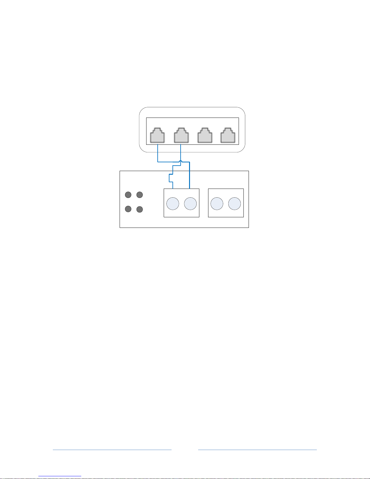
Use an optical fiber to connect MTG3000 and an optical transceiver which is under the PSTN network. The
optical fiber includes the Tx wire and the Rx wire. The Tx port of MTG3000 is connected to the Tx port of
the optical transceiver, while the Rx port of MTG3000 is connected to the Rx port of the optical transceiver.
RXTX
TX RX
0 1
SDH
0
1
PWR
RUN
Optical Transceiver
MTG3000
SFP0
2.3 Troubleshooting
When the MTG has been connected to the optical transceiver, but light 0 on the SDH board is still dull or it
flashes, please check according to the following steps.
a. Check whether the MTG3000 gateway is properly connected to the optical fiber.
b. Switch the Tx port with the Rx port of MTG3000
c. Check whether the numbers of the two ends of the optical fiber are the same.
d. Carry out a loopback test.
MTG3000 provides three methods for loopback test:
1. Loopback within a single DTU board: loopback between the front 8 virtual E1/T1 ports and back 8
virtual E1/T1 ports.
2. Loopback between DTU boards: loopback between DTU0 and DTU1; loopback between DTU1 and
DTU3.
3. User-defined loopback: loopback based on actual needs. (As for this loopback test, user needs to set
mapping relationship on the SDH Config Channel Map interface on Web).
Page 17
MTG3000 VoIP Trunk Gateway User Manual
11
Copyright @ 2011-2016 Dinstar
3 Basic Operation
3.1 Configuration of IP Address
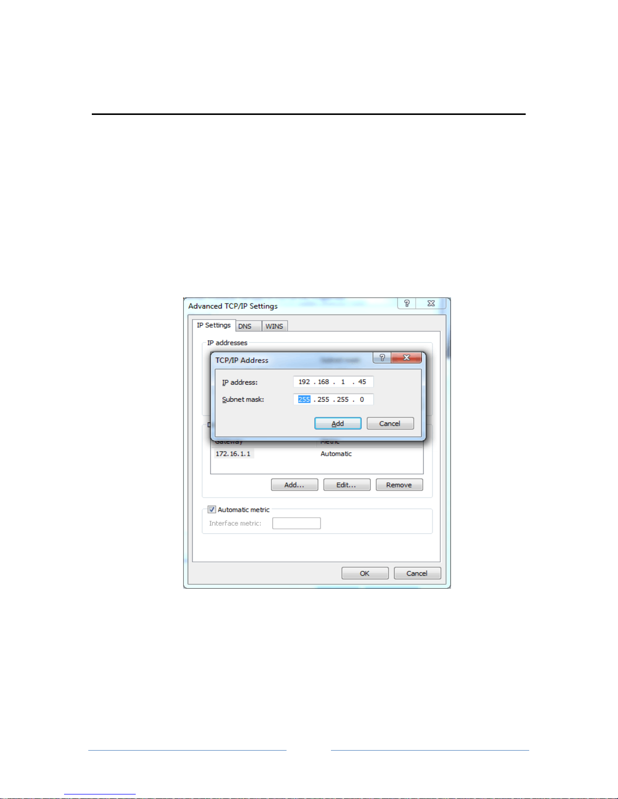
The default IP address of GE1 is 192.168.1.111, while that of GE0 is 192.168.11.1.When GE1 is in use, it’s
required that the IP address of GE1 and the IP address of PC are at the same network segment.
1. Connect the GE1 port of MTG3000 to a PC by using a network cable.
2. On the PC, open the TCP/IP Settings interface, click Advanced, and then click Add to add an IP
whose format is 192.168.1.XXX. Or you can open the Internet Protocol (TCP/IP) interface to modify an
existing IP into 192.168.1.XXX.
3.2 Local Maintenance
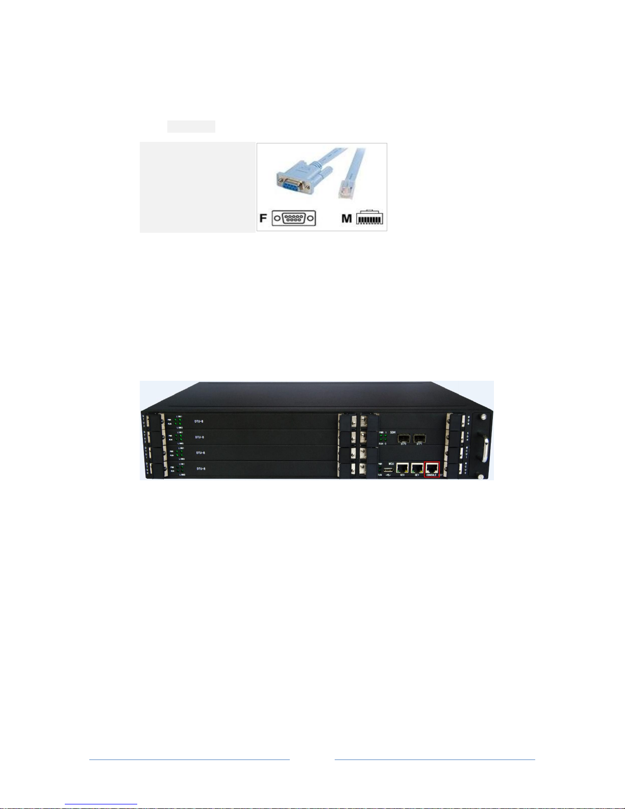
To ensure easy maintenance, the MTG3000 trunk gateway provides a standard RJ48 console port, which
has a Baud rate of 115200bps. Users can log in the MTG3000 to carry out maintenance-related
configurations through the console port.
Page 18
MTG3000 VoIP Trunk Gateway User Manual
12
Copyright @ 2011-2016 Dinstar
3.2.1 Example: Log in MTG3000 via Console Port
Step 1: Prepare a serial cable.
Step 2: Connect the F port of the serial cable to the COM port of PC.
If the PC does not have a COM port, please use a USB-to-COM converting tool to connect the serial cable
to the PC.
Step 3: Connect the M port of the serial cable to the console port of MTG3000.
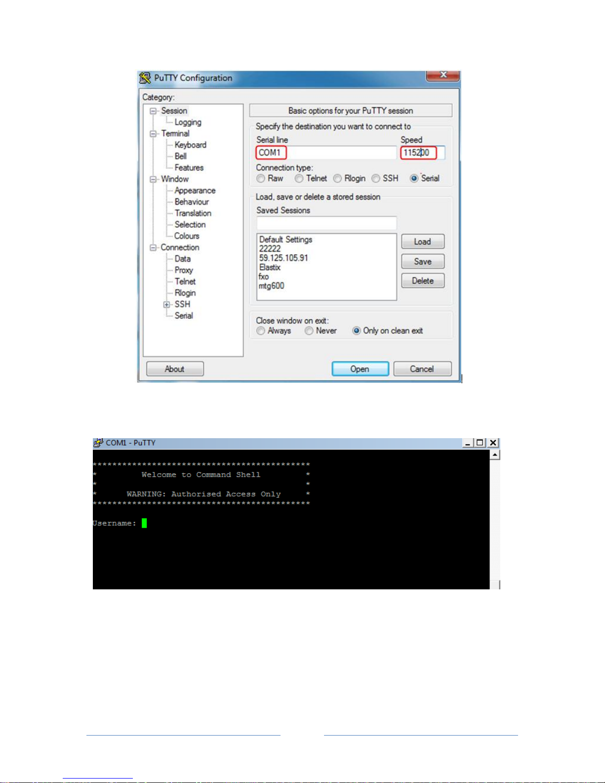
Step 4: Conduct configurations on login software.
Herein we take the PuTTY sofeware as an example. Detailed configurations are as follows:
(COM1 is an example. Please enter correct serial line according to actual conditions.)
Page 19
MTG3000 VoIP Trunk Gateway User Manual
13
Copyright @ 2011-2016 Dinstar
After finishing the above configuration, click the Open button to enter the following interface.
Enter username and password, which are the same with the username and password of the Web of
MTG3000. And then you will see a linux platform where you can carry out maintanance-related
configurations.
Note: For commands to query MTG3000 information, make reference to Chapter 6 of this manual.
Page 20
MTG3000 VoIP Trunk Gateway User Manual
14
Copyright @ 2011-2016 Dinstar
3.3 Query IP
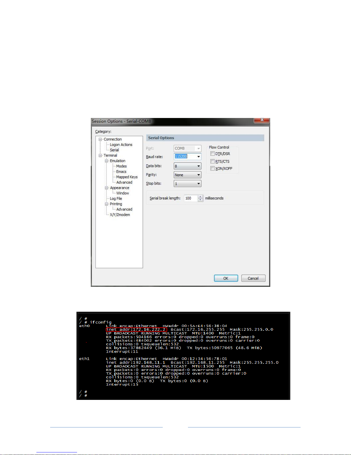
If you have changed the default IP address of GE1 or GE0 to a new IP address but forget it, you can carry
out the following procedures to query the IP address.
1. Use a serial line to connect the console port of MTG3000 with a PC;
2. Modify the baud rate to 115200;
3. Click OK, and then enter ‘ifconfig’, and the IP address of GE1 or GE0 of MTG3000 will be displayed.
Page 21
MTG3000 VoIP Trunk Gateway User Manual
15
Copyright @ 2011-2016 Dinstar
4 Configurations on Web Interface
4.1 How to Log in Web Interface
4.1.1 Network Connection
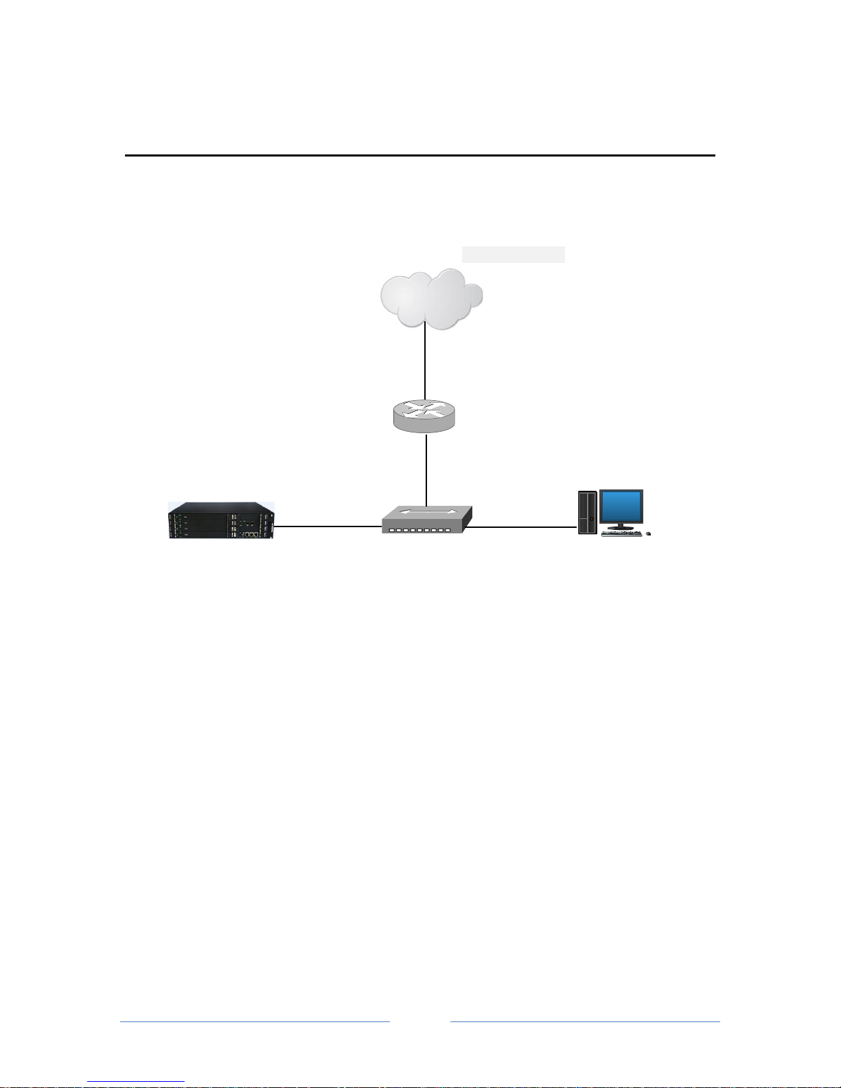
Connect MTG3000 to the network according to the following network topology:
4.1.2 Preparations for Login
Modify the IP address of the PC to make it at the same network segment with the IP address of GE1 port of
MTG3000 device. The format of PC IP is 192.168.1.XXX, since the default IP of GE1 port is
192.168.1.111.
Click Start Run on the PC and enter cmd to execute ‘ping 192.168.1.111’ to check whether the IP
address of the MTG3000 runs normally.
4.1.3 Log in Web Interface
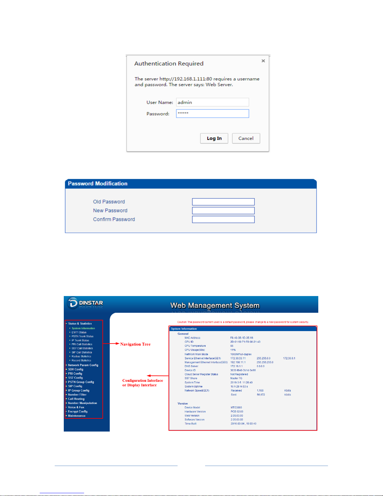
Open a web browser and enter the IP address of GE1 of MTG3000 (the default IP is 192.168.1.111). Then
the login GUI will be displayed. Both the default username and password are admin.
It is suggested that you should modify the username and password for security consideration on the
Maintenance Password Modification interface.
MTG3000
Switch
Router
Internet
PC
Page 22
MTG3000 VoIP Trunk Gateway User Manual
16
Copyright @ 2011-2016 Dinstar
Login GUI:
Password Modification Interface:
4.2 Introduction to Web Interface
The Web Interface of the MTG3000 consists of the navigation tree and detailed configuration interfaces.
Click a node of the navigation tree, and you will see a detailed display interface or configuration interface:
Page 23
MTG3000 VoIP Trunk Gateway User Manual
17
Copyright @ 2011-2016 Dinstar
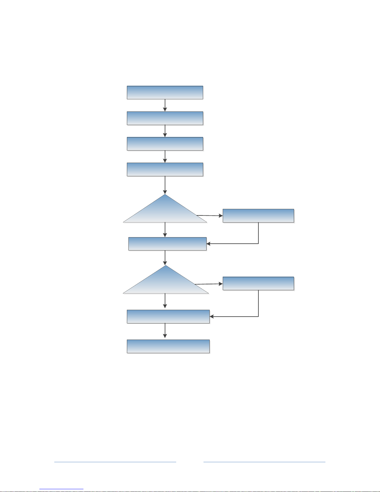
4.3 Configuration Flows
The following is the configuration flows of MTG3000:
Log in Web Interface
Configure IP Address of GE1
Configure SDH Parameters
Configure PRI/SS7 Trunk
Whether to Configure PSTN
Group
Configure PSTN Group
Configure SIP Trunk
Whether to Configure IP
Group
Configure IP Group
Configure Calling Routes
Yes
No
Yes
No
Save Configurations and Restart
MTG3000
No
4.4 Status & Statistics
4.4.1 System Information
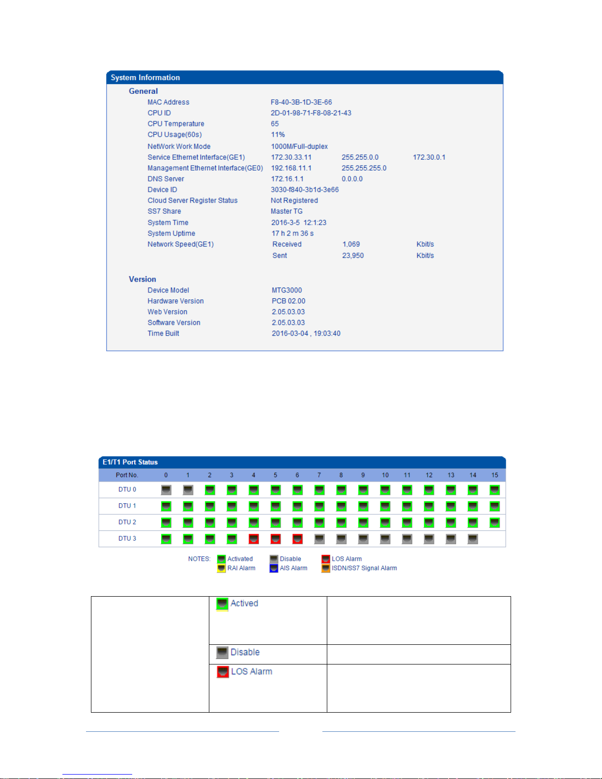
Click Status & Statistics System Information in the navigation tree on the left, and the
following interface will be displayed. On the interface, information about the system, such as Mac
address, CPU usage, hardware version and software version, are shown.
Page 24
MTG3000 VoIP Trunk Gateway User Manual
18
Copyright @ 2011-2016 Dinstar
4.4.2 E1/T1 Status
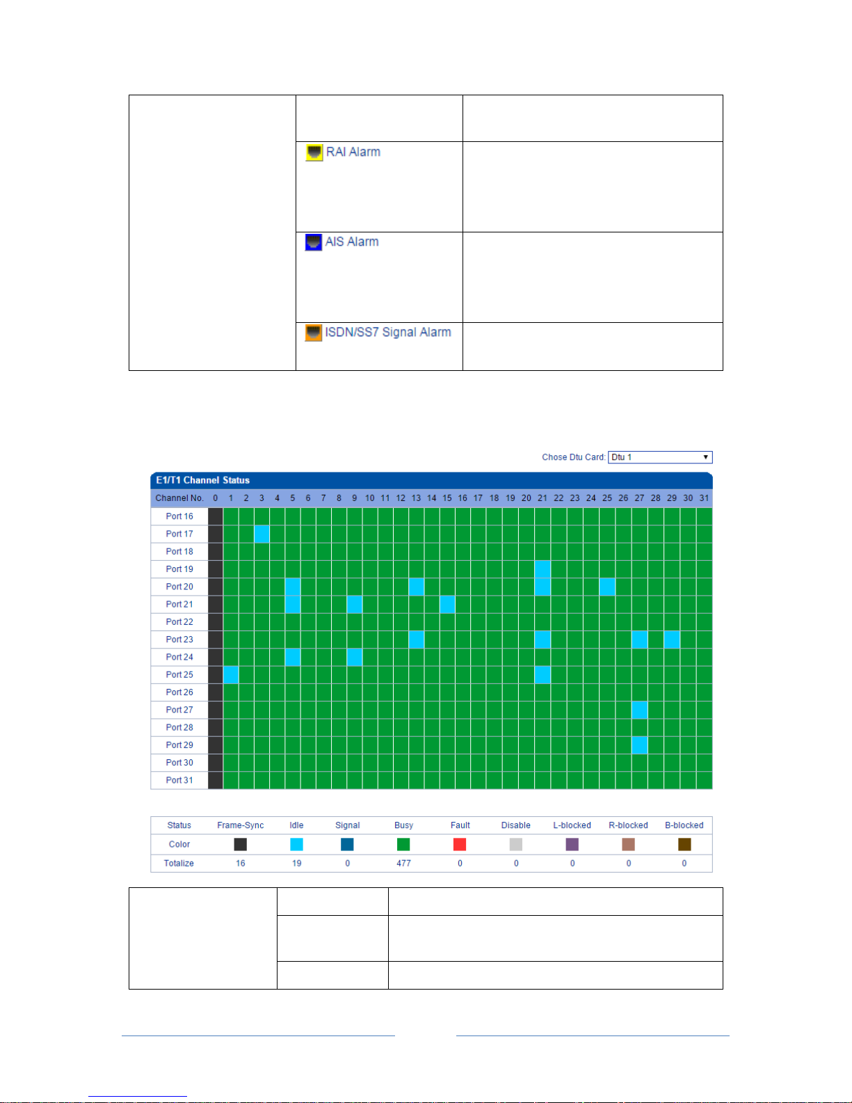
Click Status & Statistics E1/T1 Status in the navigation tree, and the status of each E1/T1 port is
displayed.
E1/T1 port status:
Status of E1/T1 Port
Both physical connection and signal
connection of the E1/T1 port are normal,
and the port is activated.
The E1/T1 port is not used.
Alarm for loss of signal. If the LOS alarm is
raised, please check physical network
connection.
Page 25
MTG3000 VoIP Trunk Gateway User Manual
19
Copyright @ 2011-2016 Dinstar
Status of E1/T1 Port
RAI (Remote Alarm Indication) is an alarm
for lost of remote signal. The alarm is sent
by the remote device and received by
MTG3000.
AIS (Alarm Indication Signal) is an alarm
raised by MTG3000, indicating the peer
device malfunctions, or signal/physical
connections are abnormal.
This alarm means physical connection is
normal while signal connection is abnormal.
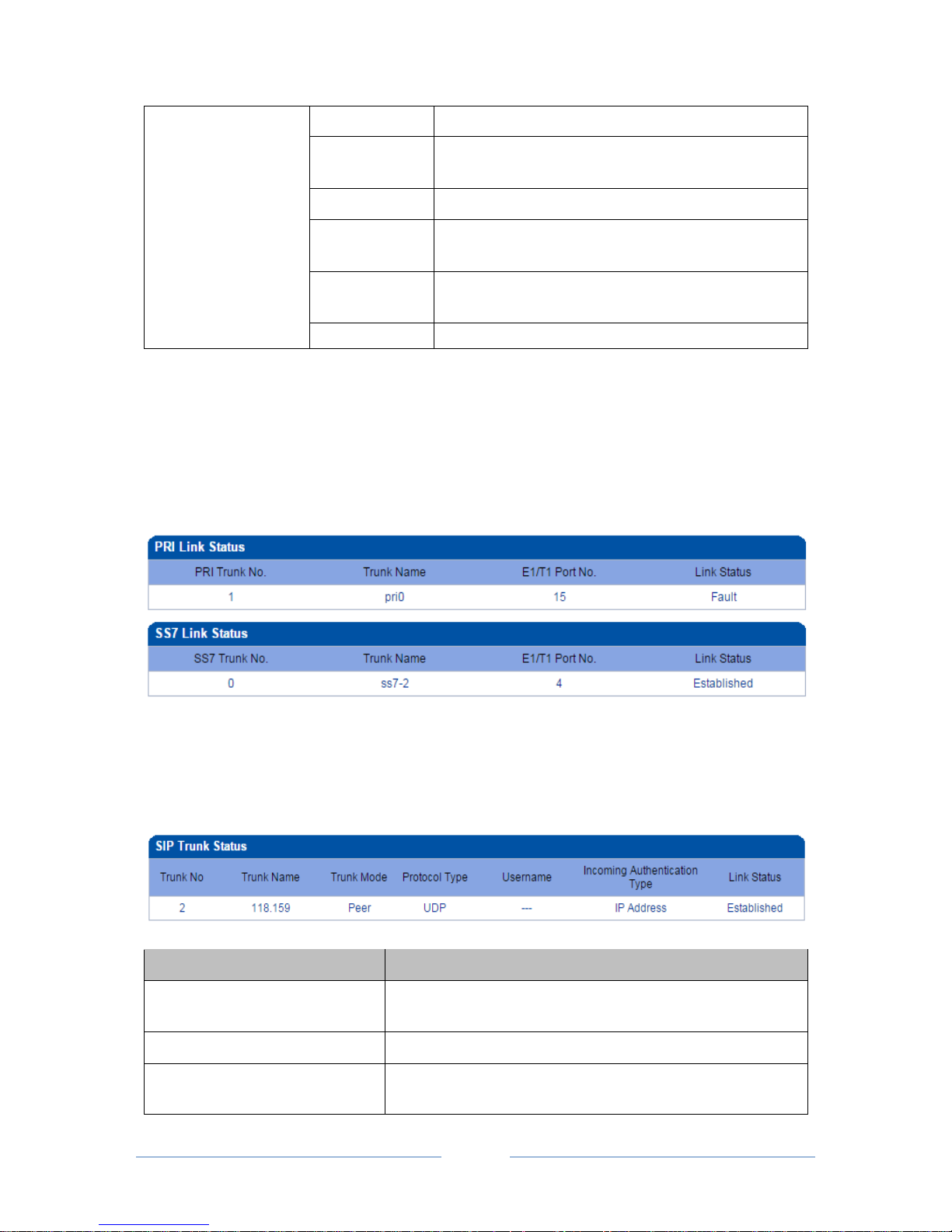
Channel status:
Select DTU card number to check the channel status of each DTU board.
E1/T1 Channel Status
Frame-Sync
Frame synchronization
Idle
The channel is available, and related cables are connected
normally.(The channel is used to transmit voice)
Signal
The channel is used to transmit signal.
Page 26
MTG3000 VoIP Trunk Gateway User Manual
20
Copyright @ 2011-2016 Dinstar
E1/T1 Channel Status
Busy
The E1/T1 channel is being used by voice.
Fault
The channel is normal while cables are not successfully
connected.
Disable
The E1/T1 trunk is not used.
L-blocked
The E1/T1 channel is blocked at local end, but not
blocked at remote end.
R-blocked
The E1/T1 channel is blocked at remote end, but not
blocked at local end.
B-block
The E1/T1 is blocked at both local end and remote end.
4.4.3 PSTN Trunk Status
On the PSTN Trunk Status interface, the statuses of PRI/SS7 trunks are displayed. The PRI/SS7 trunks
under PSTN need to be established at the PRI Config PRI Trunk interface or the SS7 Config SS7
Trunk interface first.
4.4.4 IP Trunk Status
On the IP Trunk Status interface, the statuses of SIP trunks are displayed. The SIP trunks need to be
established at the SIP Config SIP Trunk interface first.
Parameter
Explanation
Trunk Name
This trunk name is the name used to register the SIP trunk. If the
SIP trunk is not registered, the trunk name is displayed as “---”.
Trunk Mode
There are two trunk modes: peer (peer-to-peer) and access.
Incoming Authentication Type
Incoming calls can be authenticated through password or IP
address.
Page 27
MTG3000 VoIP Trunk Gateway User Manual
21
Copyright @ 2011-2016 Dinstar
Link Status
There are two link statuses: Established and Fault.
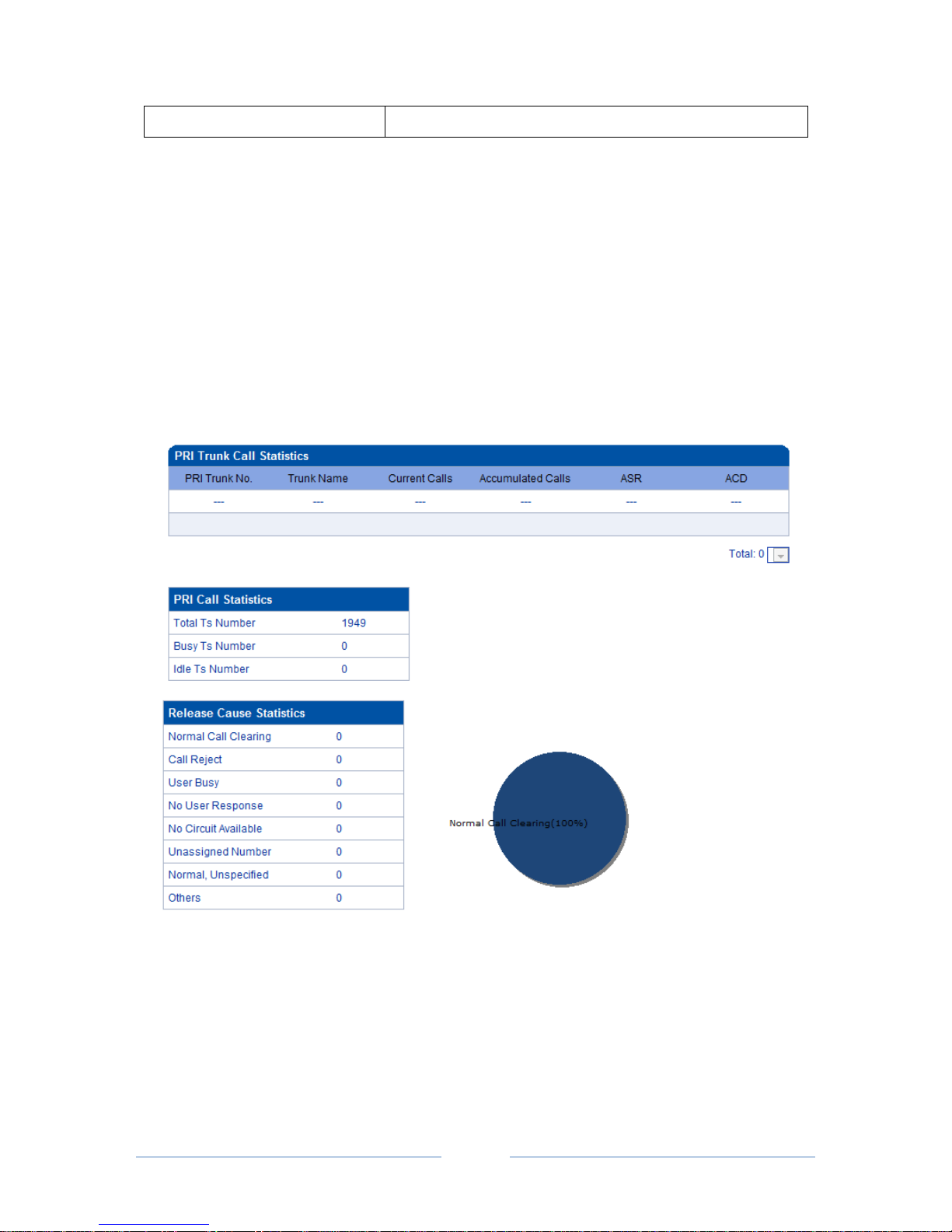
4.4.5 PRI Call Statistics
On the PRI Call Statistics interface, information about PRI calls and statistics about call release causes are
displayed.
ASR (Answer-seizure Ratio): is a call success rate, which reflects the percentage of answered telephone
calls with respect to the total call volume. ASR = answered call/total attempts of calls.
ACD (Average Call Duration): is a measurement in telecommunication, which reflects an average length
of telephone calls transmitted on telecommunication networks. ACD = total call duration/total connected
calls.
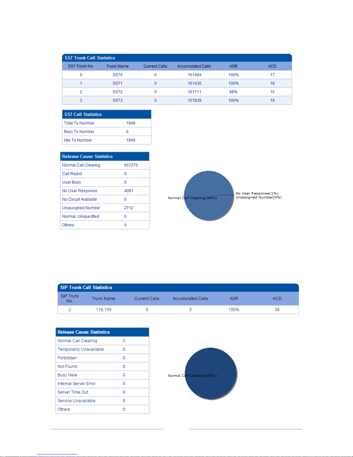
4.4.6 SS7 Call Statistics
On the SS7 Call Statistics interface, information about SS7 calls and statistics about call release causes are
displayed.
Page 28
MTG3000 VoIP Trunk Gateway User Manual
22
Copyright @ 2011-2016 Dinstar
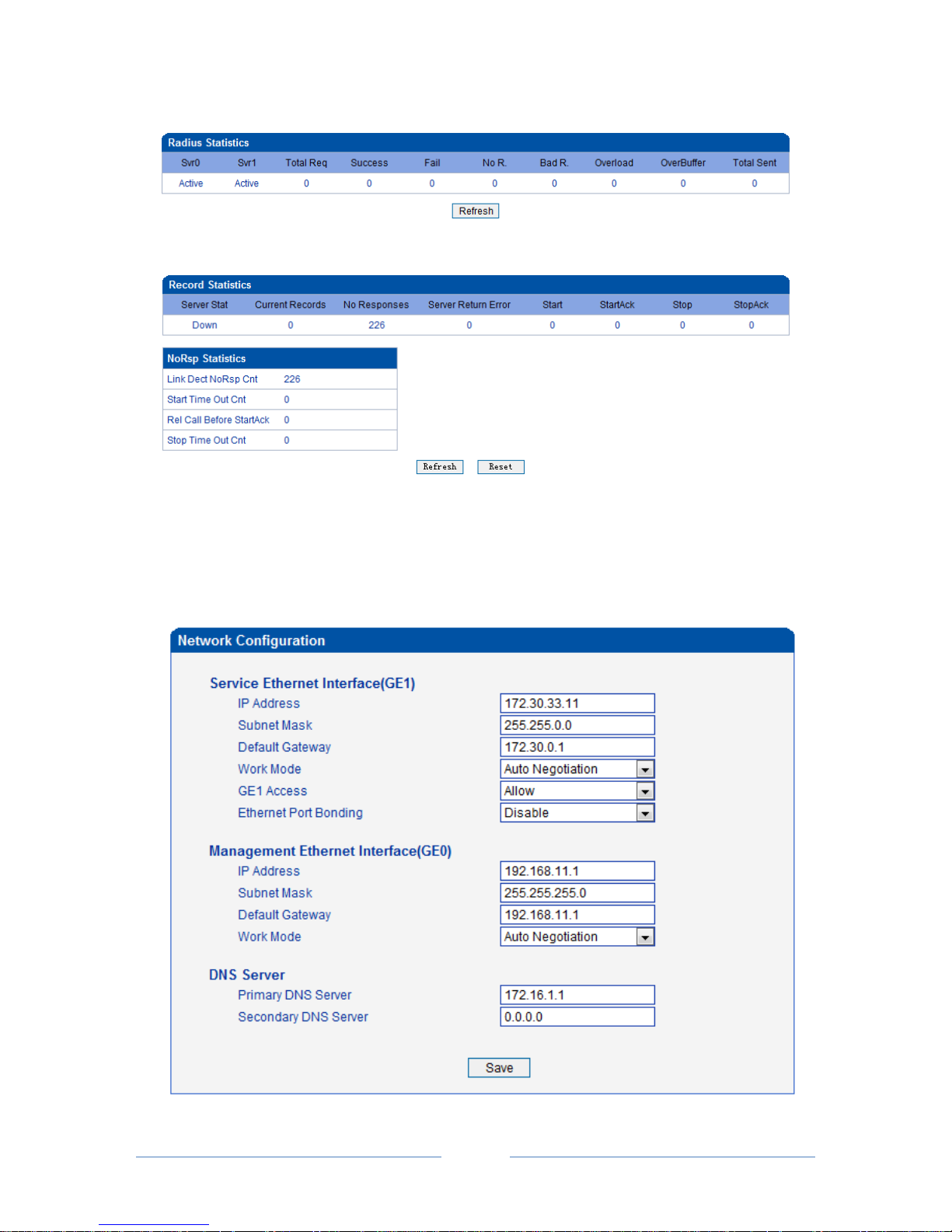
4.4.7 SIP Call Statistics
On the SIP Call Statistics interface, information about SIP calls and statistics about call release causes are
displayed.
Page 29
MTG3000 VoIP Trunk Gateway User Manual
23
Copyright @ 2011-2016 Dinstar
4.4.8 Radius Statistics
4.4.9 Record Statistics
4.5 Network
Generally, it’s necessary to modify the default IP address of GE1 according to actual network conditions,
and then modify the IP address of PC to make it at the same network segment with the IP address of GE1.
After completing the configurations, you need to restart the MTG3000 device for the changes to take effect.
Page 30

MTG3000 VoIP Trunk Gateway User Manual
24
Copyright @ 2011-2016 Dinstar
Belong to
Parameter
Explanation
GE1 Port
IP Address
The IP address of GE1, default value is 192.168.1.111
Subnet Mask
Subnet mask of GE1
Default Gateway
The IP address of network gateway
Work Mode
Include Auto Negotiation, 1000M/Full-Duplex,
100M/Full-Duplex, 100M/Half-Duplex.
Full-Duplex: Communication in both directions
simultaneously;
Half-Duplex: Communication only in one direction.
GE1 Access
Deny: Users cannot access the Web interface through
GE1, but MTG3000 works normally.
Allow: All users can access the Web interface through
GE1.
GE0 Port
IP Address
The IP address of GE0, default value is 192.168.11.1
Subnet Mask
Subnet mask of GE0
Work Mode
Same with Word Mode of GE1
DNS
Primary DNS Server
The IP address of the primary DNS server
Secondary DNS
Sever
The IP address of the secondary DNS server. It is
optional to fill in.
Note: The IP address of GE1 and that of GE0 cannot be at the same network segment.
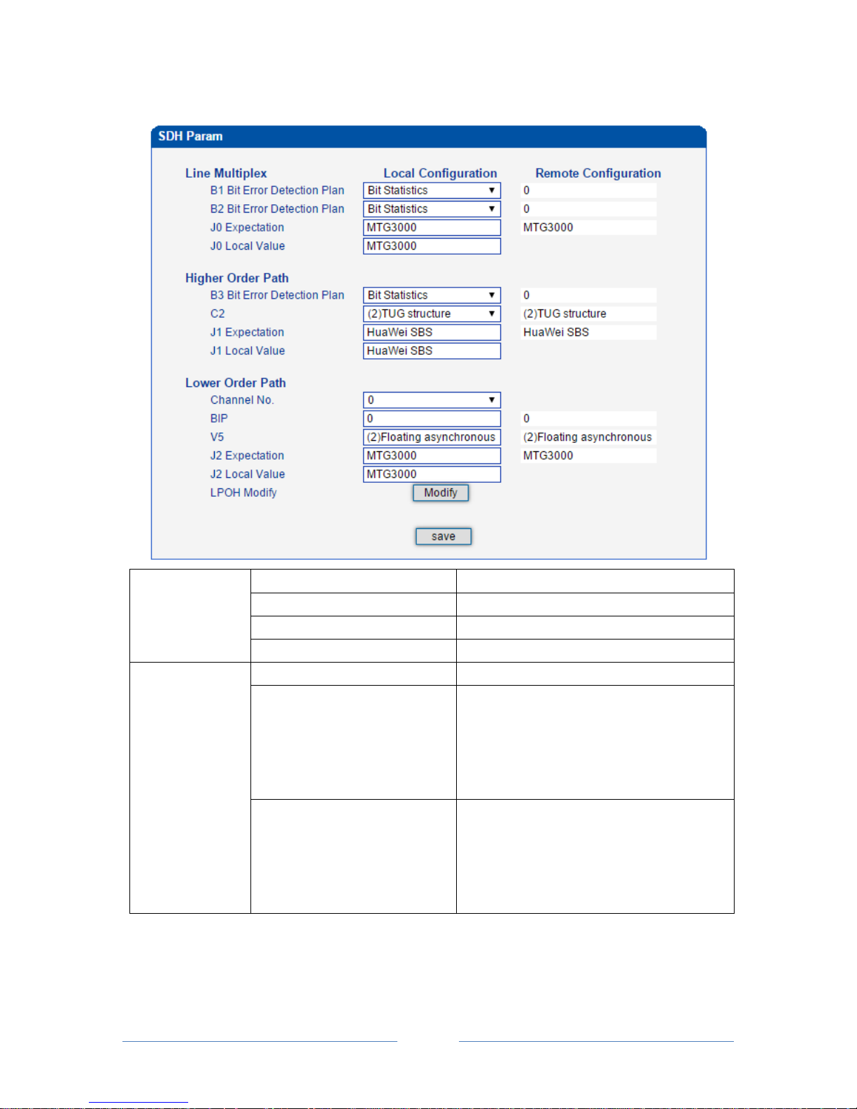
4.6 SDH Config
SDH configuration includes Line Multiplex, Higher Order Path and Lower Order Path.
Page 31
MTG3000 VoIP Trunk Gateway User Manual
25
Copyright @ 2011-2016 Dinstar
4.6.1 SDH Param
Line Multiplex
B1 Bit Error Detection Plan
Choose ‘Bit Statistics’ or ‘Block Statistics’
B2 Bit Error Detection Plan
Choose ‘Bit Statistics’ or ‘Block Statistics’
J0 Expectation
MTG3000
J0 Local Value
MTG3000
Higher Order Path
B3 Bit Error Detection Plan
Choose ‘Bit Statistics’ or ‘Block Statistics’
J1 Expectation
It is used to check whether optical transceiver
is telecommunicating normally with
MTG3000. When it is the same with J1 local
value, it means telecommunication between
MTG3000 and optical transceiver is normal.
J1 Local Value
It is used to check whether MTG3000 is
telecommunicating normally with the optical
fiber. When it is the same with J1 expectation,
it means telecommunication between
MTG3000 and optical transceiver is normal.
Note:
Please ensure parameters related to J0, C2, J1, V5 and J2 are consistent with those configured on optical
transceiver.
Page 32
MTG3000 VoIP Trunk Gateway User Manual
26
Copyright @ 2011-2016 Dinstar
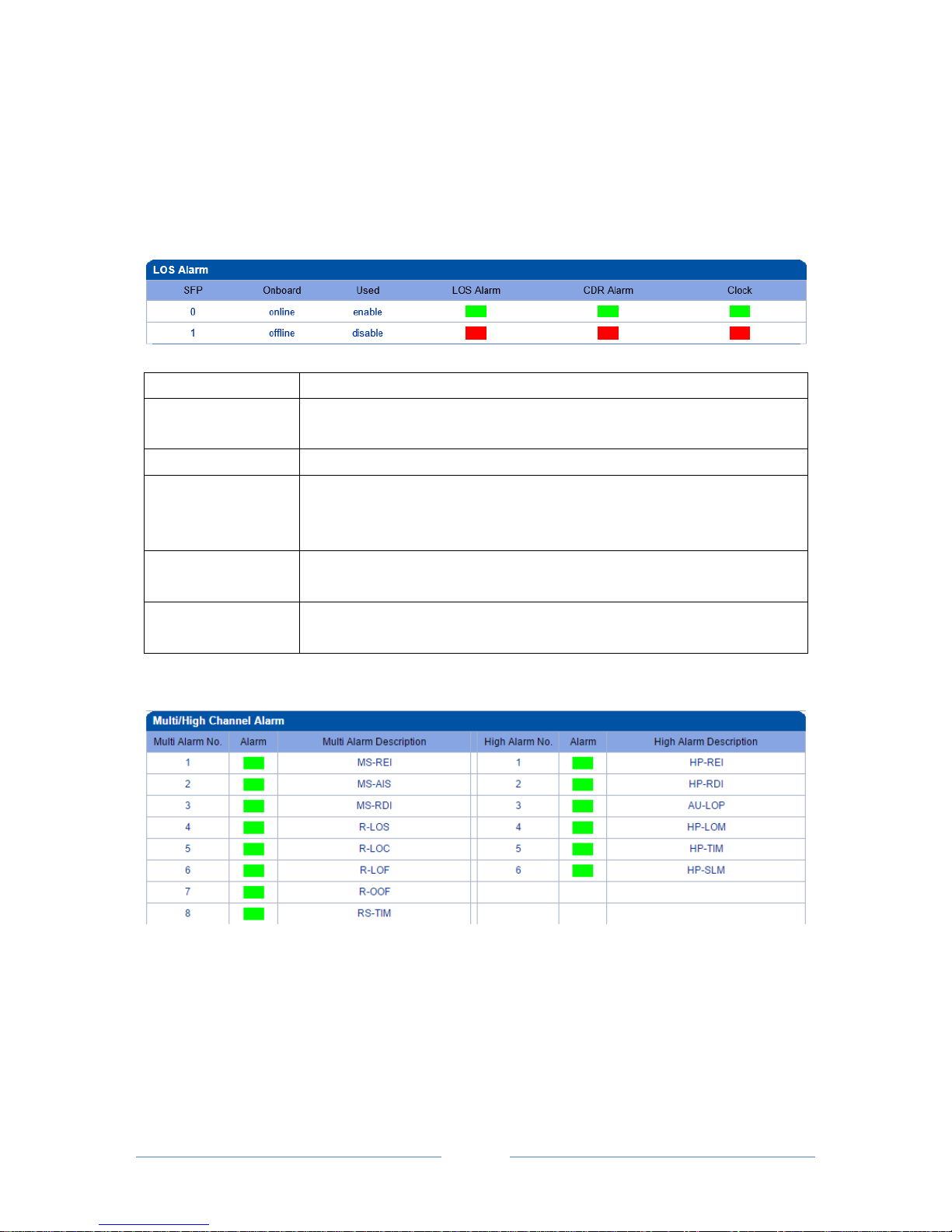
4.6.2 SDH Alarm
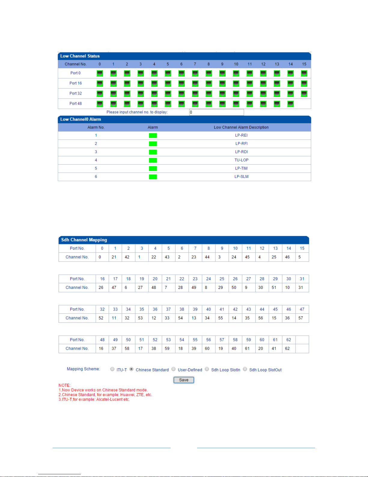
SDH alarm includes LOS alarm, multi/high channel alarm, low channel X alarm (X can be any digit
between 0 and 62).
LOS Alarm
SFP
There are two SFP optical modules, namely SFP 0 and SFP 1.
Onboard
Display the status of SFP optical modules. Online means SFP optical module
has been inserted. Offline means SFP optical module is not inserted.
Used
Display SFP port is enabled or disabled.
LOS Alarm
Green: signal is received.
Red: signal is lost (the reason may be the optical fiber is not connected
properly).
CDR Alarm
Green: CDR successfully parses data signal and clock
Red: CDR fail to parses data signal and clock
Clock
Green: Clock is parsed and locked
Red: Clock fails to be parsed
Multi/High Channel Alarm
Page 33
MTG3000 VoIP Trunk Gateway User Manual
27
Copyright @ 2011-2016 Dinstar
Low Channel Status and Alarm
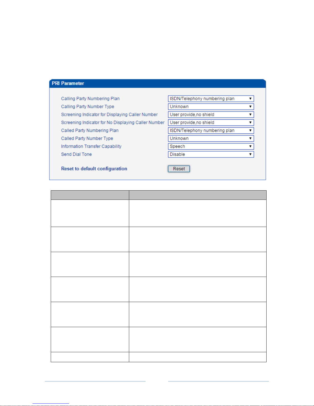
4.6.3 Channel Map
Generally, mapping scheme is ITU-T. User can also customize mapping relationship on this interface. The
mapping carried out on MTG3000 must be the same with that on optical transceiver.
Page 34
MTG3000 VoIP Trunk Gateway User Manual
28
Copyright @ 2011-2016 Dinstar
4.7 PRI Config
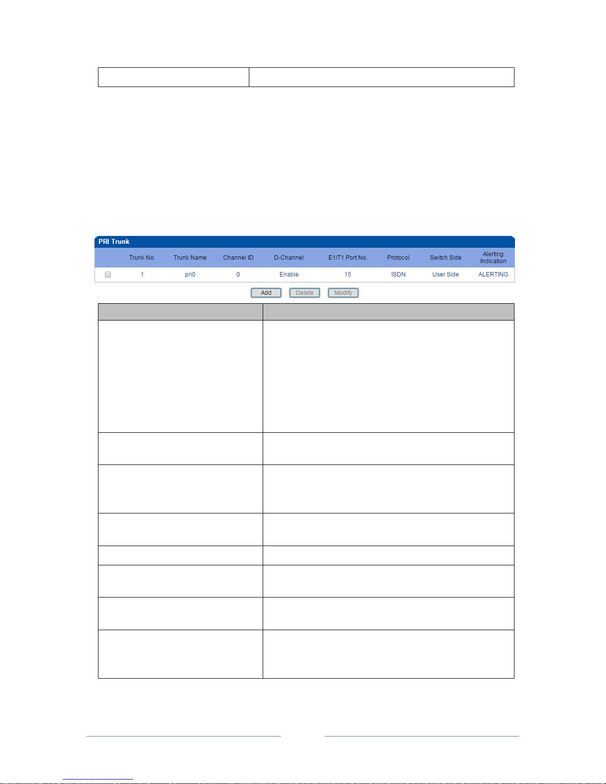
4.7.1 PRI Parameter
Configure PRI parameters according to actual data which are provided by telecom operators.
Parameter
Options
Calling Party Numbering Plan
Include ‘ISDN/Telephony Numbering Plan’, ‘Data Numbering
Plan’, ‘Telex Numbering Plan’, ‘National Standard Numbering
Plan’, ‘Private Numbering Plan’ and ‘Unknown’.
Calling Party Number Type
Include ‘International Number’, ‘National Number’, ‘Network
Specific Number’, ‘Subscriber Number’, ‘Abbreviated Number’
and ‘Unknown’.
Screening Indicator for Displaying
Caller Number
Include ‘User-provided, not screened’, ‘User-provided, verified
and passed’, ‘User-provided, verified and failed’,
‘Network-provided’
Screening Indicator for No
Displaying Caller Number
Include ‘User-provided, not screened’, ‘User-provided,
verified and passed’, ‘User-provided, verified and failed’,
‘Network-provided’
Called Party Numbering Plan
Include ‘ISDN/Telephony Numbering Plan’, ‘Data Numbering
Plan’, ‘Telex Numbering Plan’, ‘National Standard Numbering
Plan’, ‘Private Numbering Plan’ and ‘Unknown’.
Called Party Number Type
Include ‘International Number’, ‘National Number’, ‘Network
Specific Number’, ‘Subscriber Number’, ‘Abbreviated Number’
and ‘Unknown’.
Information Transfer Capability
Include ‘Speech’ and ‘3.1 kHz audio’
Page 35
MTG3000 VoIP Trunk Gateway User Manual
29
Copyright @ 2011-2016 Dinstar
Send Dial Tone
Enable and Disable
4.7.2 PRI Trunk
On the PRI Trunk interface, you can configure PRI trunks for PRI calls. The statuses of PRI Trunks can be
seen at the Status & Statistics PSTN Trunk Status interface.
Click the Add button, and you can add a PRI trunk. If you want to delete or modify the information of a
PRI trunk, select the checkbox on the left of the trunk, and then click the Delete button or the Modify
button.
Parameter
Explanation
Trunk No.
Trunk No. starts from 0 to 19, it means you can establish 20
PRI trunks at most.
The trunk No. is decided by the No. of the E1/T1 port linked
to the trunk. But if D-channel is not enabled for a trunk, the
No. of the trunk must be the same with a trunk under which
D-channel has been enabled.
Trunk Name
The trunk name is used to distinguish the trunk from other
trunks.
Channel ID
The ID of the channel selected for the PRI trunk. The
channel ID is used for the switch to identify a PRI trunk in
case that the Trunk No. of two trunks are the same.
D-Channel
(Delta Channel)
The channel used to carry control information and signaling
information
E1/T1 Port No.
The No. of E1/T1 port linked to the PRI trunk
Protocol
Support two protocols: ISDN and QSIG. Default value is
ISDN.
Switch Side
The EI/T1 port of the PRI trunk is taken as User Side or
Network Side.
Alerting Indication
Include Alerting and Progress
Alerting: Play ring-back tone when receiving alerting signal
Progress: Play ring-back tone when receiving progress signal
Page 36
MTG3000 VoIP Trunk Gateway User Manual
30
Copyright @ 2011-2016 Dinstar
4.8 SS7 Config
4.8.1 SS7 Parameter
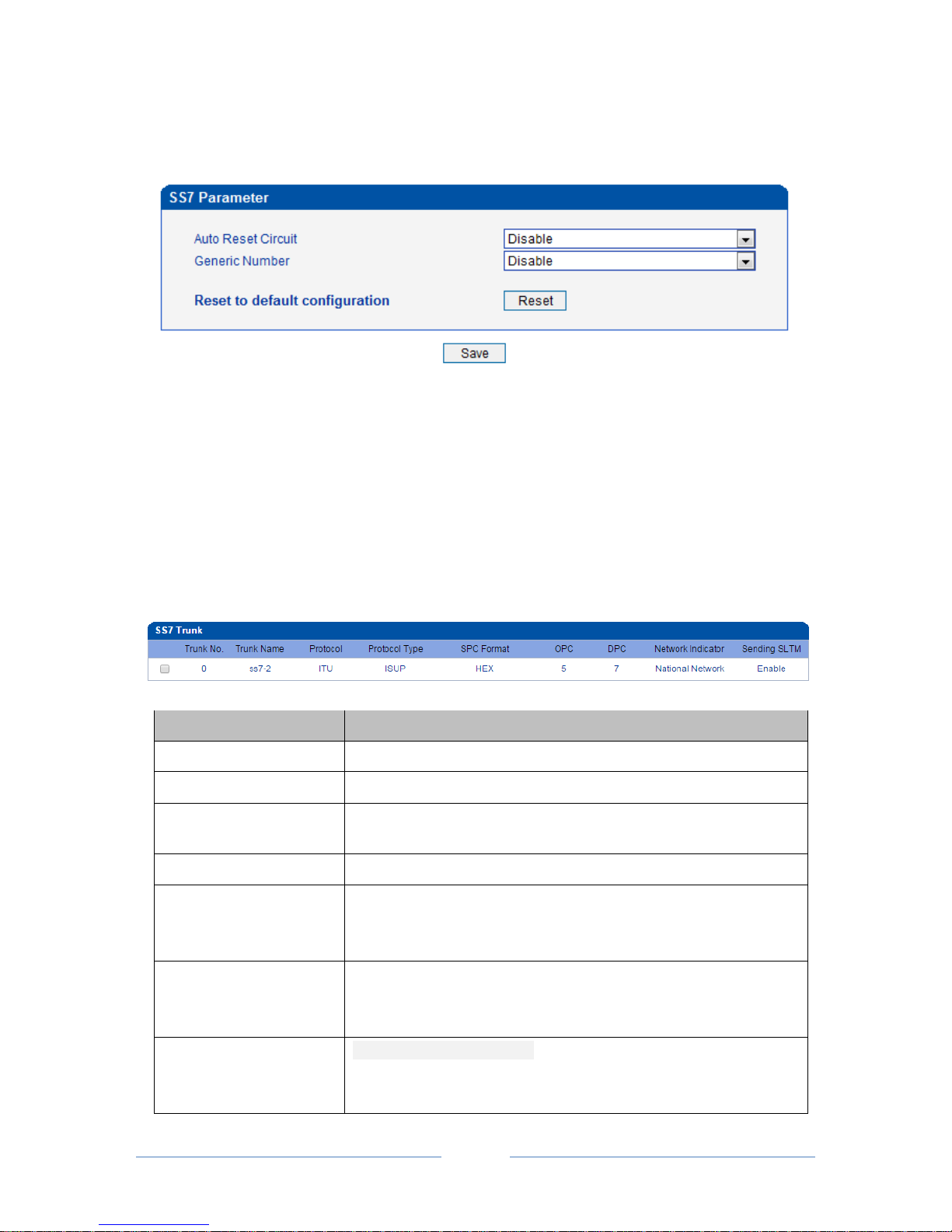
Auto Reset Circuit indicates that the gateway send “GRS” or “CGU” message to the switch side to initiate
circuits when the MTP links up. Disable this message in case of the switch side doesn’t response to “GRS”
properly.
Select “enable/disable” through drop box.
4.8.2 Create SS7 Trunks
On the SS7 Config SS7 Trunk interface, you can configure SS7 trunks for SS7 calls. The statuses of
SS7 Trunks can be seen at the Status & Statistics PSTN Trunk Status interface.
Parameter
Explanation
Trunk No.
The No. of the SS7 trunk. Generally, one SS7 trunk is for one DPC.
Trunk Name
The trunk name is used to distinguish the trunk from other trunks.
Protocol
SPC types: ITU-T (14 bit), ANSI (24 bit), ITU-CHINA (24 bit)
SPC: Signaling Point Code
Protocol Type
ISUP (ISDN User Part) and TUP (Telephone User Part)
SPC Format
SPC: Signaling Point Code
SPC format includes Hex (Hexadecimal system) and ITU point code
structure (decimal system)
OPC
OPC: Original Point Code
The signaling point code of MTG3000, which is generally assigned by
telecom operators.
DPC
DPC: Destination Point Code
The signaling point code of the peer device, which is generally assigned
by telecom operators.
Page 37
MTG3000 VoIP Trunk Gateway User Manual
31
Copyright @ 2011-2016 Dinstar
Network Indicator
Include International Network, International Spare, National Network
and National Spare.
Default value is National Network, which is mainly used in China,
America and Japan.
Sending SLTM
Whether to send signaling link test message.
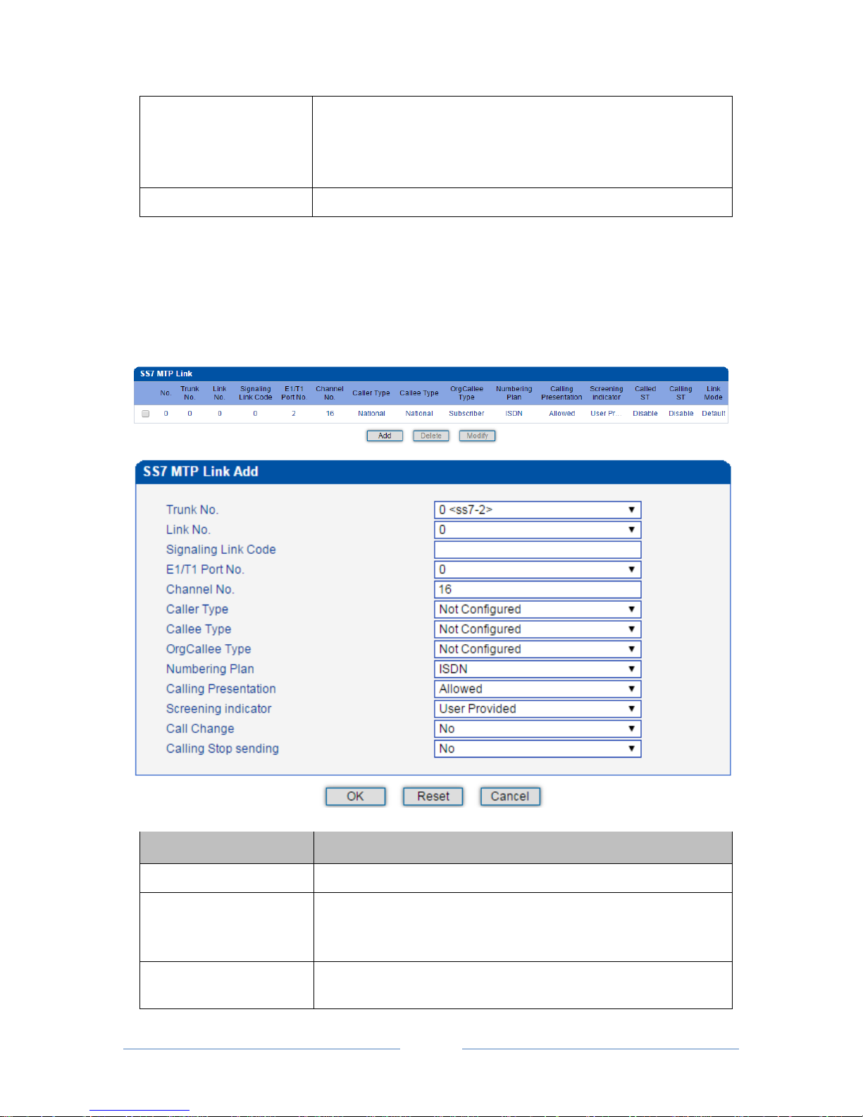
4.8.3 SS7 MTP Link
On the SS7 Config SS7 MTP Link interface, click the Add button, and you will see the following
interface. On the interface, you can select an E1/T1 port for an existing trunk and establish two links
between them.
Parameter
Explanation
Trunk No.
The No. of the SS7 trunk
Link No.
Each SS7 trunk supports two links which share the loading equally. If
one link malfunctions, the other link will automatically bear all the
loading until the faulty link is restored.
Signaling Link Code
If the Link No. of the trunk cannot match with that of the peer device,
the SS7 trunk will be linked to the peer device according to signaling
Page 38

MTG3000 VoIP Trunk Gateway User Manual
32
Copyright @ 2011-2016 Dinstar
link code.
E1/T1 Port No.
The No. of E1/T1 port linked to the SS7 trunk
Channel No.
The No. of the channel under which signal is transmitted. Default value
is 16.
Caller Type
The type of the caller number. Options include ‘Not Configured’,
‘Subscriber’, ‘International” and “National’.
Callee Type
The type of the called number. Options include ‘Not Configured’,
‘Subscriber’, ‘International” and ‘National’.
OrgCallee Type
The type of the original called number in case of number manipulation.
Options include ‘Not Configured’, ‘Subscriber’, ‘International’ and
‘National’.
Numbering Plan
Options include ‘ISDN’, ‘Data’, ‘Telex’ and ‘Private’.
Calling Presentation
If ‘Allowed’ is selected, the calling number will be presented.
If ‘Restricted’ is selected, the calling number will not be presented.
If ‘Not Config’ is selected, the parameter does not work.
Screening Indicator
Options include “User Provided” and “Network Provided”.
Calling Stop Sending
‘Stop Sending’ is an end mark. If ‘Yes’ is selected for ‘Calling Stop
Sending’, it means there will be an end mark following the calling
number.
4.8.4 SS7 CIC
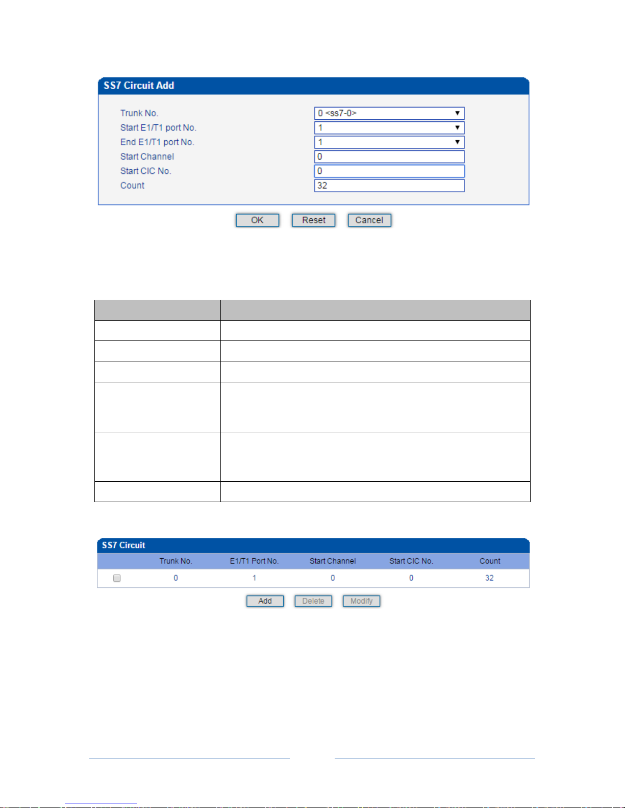
On the SS7 Config SS7 CIC interface, click the Add button, and you will see the following interface.
You can determine which channels will be used by an SS7 trunk on the interface.
Procedures for adding SS7circuit that only involves an E1/T1 port:
Step 1: Click Add on the SS7 CIC interface.
Step 2: Select a trunk and an E1/T1 port. (Trunk 0 and Port 1 are taken as example in the following figure
Page 39
MTG3000 VoIP Trunk Gateway User Manual
33
Copyright @ 2011-2016 Dinstar
Note:
As there are 32 channels (from 0 to 31) for one E1/T1 port, so the value for Count is 32. When start
E1/T1 port is the same with end E1/T1 port, it means only one E1/T1 port is connected to the SS7 trunk.
Parameter
Explanation
Trunk No.
The No. of the SS7 trunk
Start E1/T1 Port No.
The No. of the start E1/T1 port
End E1/T1 Port No.
The No. of the end E1/T1 port
Start Channel
When the start E1/T1 port is also the end E1/T1 port, it’s required to set
the start channel, and the channels starting from the set channel to the
No.31 channel of the E1/T1 port will be used by the SS7 trunk.
Start CIC No.
CIC: Circuit Identification Code
The CIC No. of the start channel, which is generally 0, 32, 64, 96, 128,
160, 192, 224, 256, 288, 320, 352, 384, 416, 448…
Count
The total number of the channels used by the SS7 trunk
Step3: Click OK. And then you can see the following data on the SS7 CIC interface.
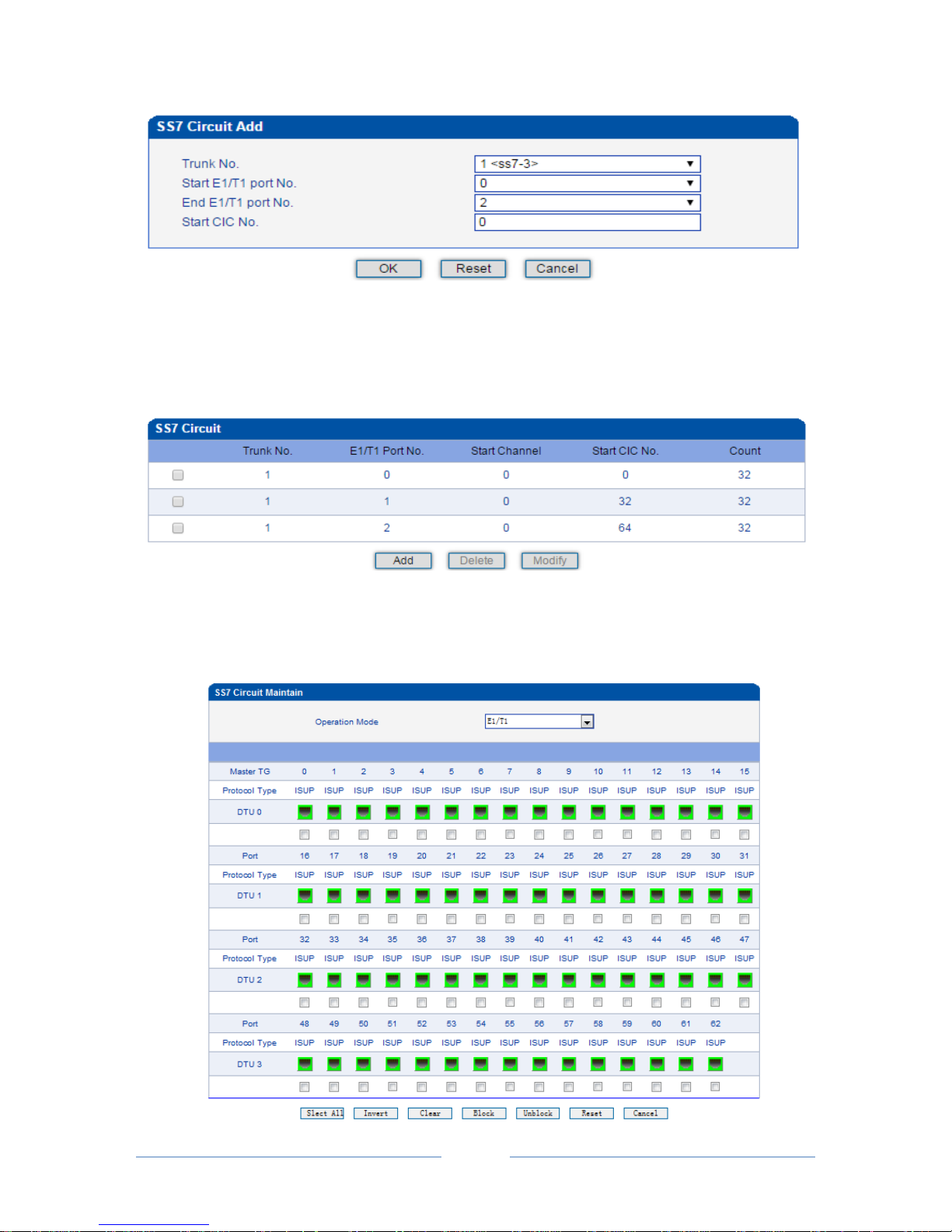
Procedures for adding SS7circuit that involves multiple E1/T1 ports:
Step 1: Click Add on the SS7 CIC interface.
Step 2: Select a trunk and E1/T1 ports. (Trunk 1, Port 0, Port1 and Port 2 are taken as example in the
following figure.
Page 40
MTG3000 VoIP Trunk Gateway User Manual
34
Copyright @ 2011-2016 Dinstar
Note: If multiple E1/T1 ports are involved, it defaults that all the 32 channels of each E1/T1 port involved
are used by the SS7 trunk.
Step3: Click OK. And then you can see the following data on the SS7 CIC interface.
4.8.5 SS7 CIC Maintain
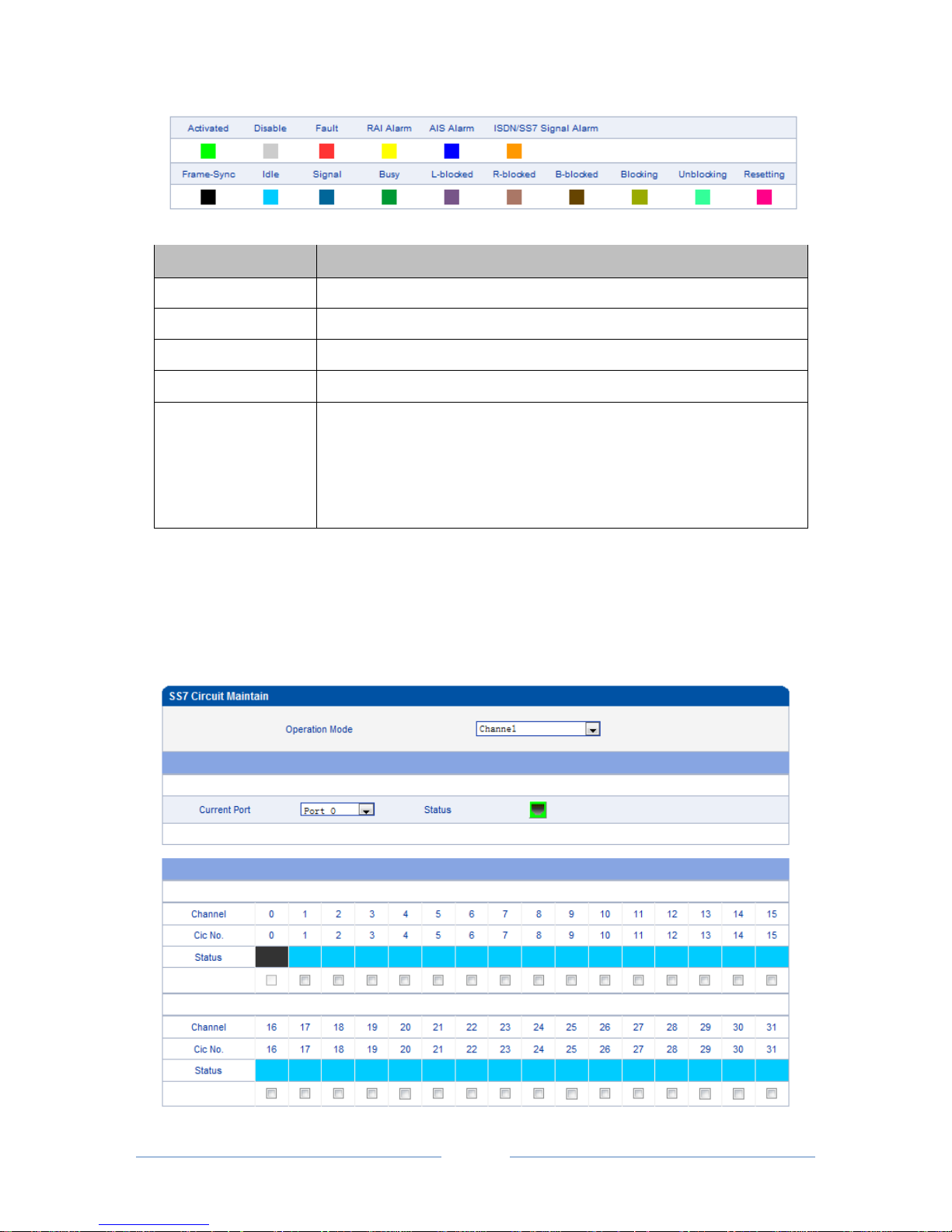
There are two objects to be maintained for SS7 CIC, namely E1/T1 ports and channels. Select E1/T1 on the
right of Operation Mode, and the following interface will be displayed.
Page 41
MTG3000 VoIP Trunk Gateway User Manual
35
Copyright @ 2011-2016 Dinstar
Parameters
Explanation
Operation Mode
E1/T1
Port
The No. of E1/T1 port
Protocol Type
ISUP or TUP
DTU
The No. of DTU which the E1/T1 ports belong to
Status
The E1/T1 ports have 16 statuses, including Activated, Disabled, Fault, RAI
Alarm, AIS Alarm, ISDN/SS7 Signal Alarm, Frame-Sync, Idle, Signal, Busy,
L-block, R-blocked, B-blocked, Blocking, Unblocking and Resetting.
The meaning of each status, please make reference to 4.4.2.
Meanwhile, you can carry out maintenance on the E1/T1 ports through the following buttons: Select All,
Invert, Clear, Block, Unblock, Reset and Cancel.
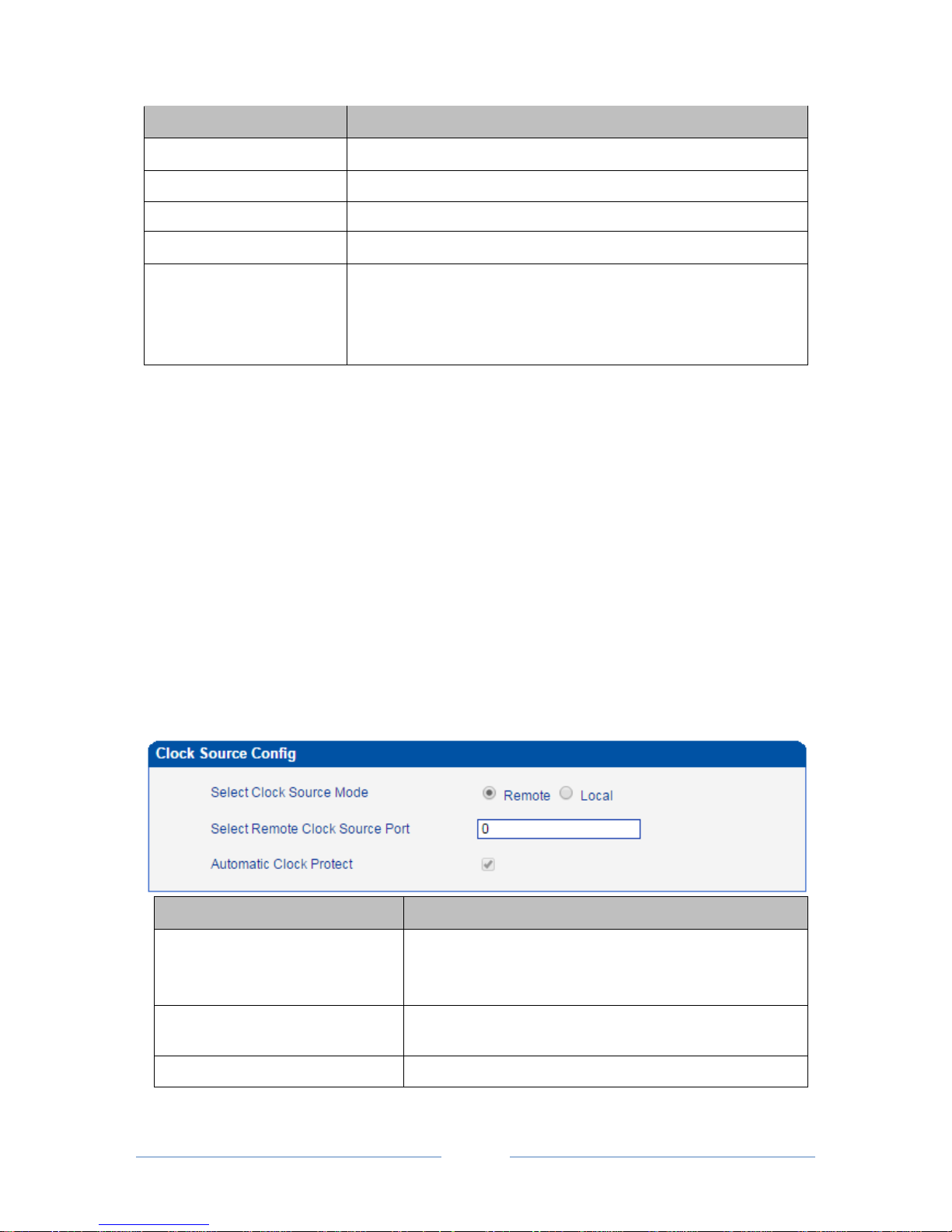
Select Channel on the right of Operation Mode, and then select an E1/T1 port, the channels of the E1/T1
port and their statuses are displayed.
Page 42
MTG3000 VoIP Trunk Gateway User Manual
36
Copyright @ 2011-2016 Dinstar
Parameter
Explanation
Operation Mode
Channel
Current Port
The No. of the current E1/T1 port
Channel
The No. of channels
CIC No.
The CIC No. of channels
Status
The statuses of channels, including Activated, Disabled, Fault, RAI
Alarm, AIS Alarm, ISDN/SS7 Signal Alarm, Frame-Sync, Idle, Signal,
Busy, L-block, R-blocked, B-blocked, Blocking, Unblocking and
Resetting.
Meanwhile, you can carry out maintenance on the channels of E1/T1 ports through the following buttons:
Select All, Invert, Clear, Block, Unblock, Reset and Cancel.
4.9 PSTN Group Config
In this section, you can group several PRI trunks or SS7 trunks together, so when one trunk is in an outage,
communication can turn to another trunk in the same group.
4.9.1 Clock Source
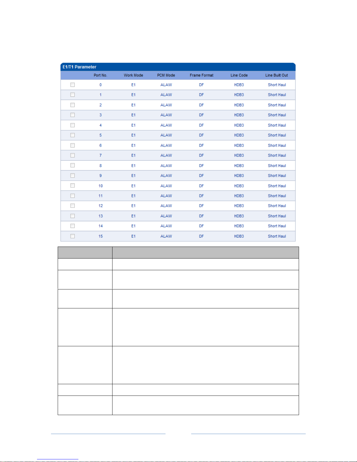
When clock source is produced by the local crystal chip of MTG3000, it is regarded as local clock source.
When clock source is obtained from the data received by E1/T1 ports, it is regarded as remote clock source.
Each E1/T1 port can obtain one clock source.
Parameter
Explanation
Select Clock Source Mode
If Remote is selected, clock source is produced by crystal chip;
if local is selected, clock source is obtained from the data
received by E1/T1 port.
Select Remote Clock Source Port
The No. of the E1/T1 port from which clock source is
obtained.
Automatic Clock Protect
Clock source is protected automatically.
Page 43
MTG3000 VoIP Trunk Gateway User Manual
37
Copyright @ 2011-2016 Dinstar
4.9.2 E1/T1 Parameter
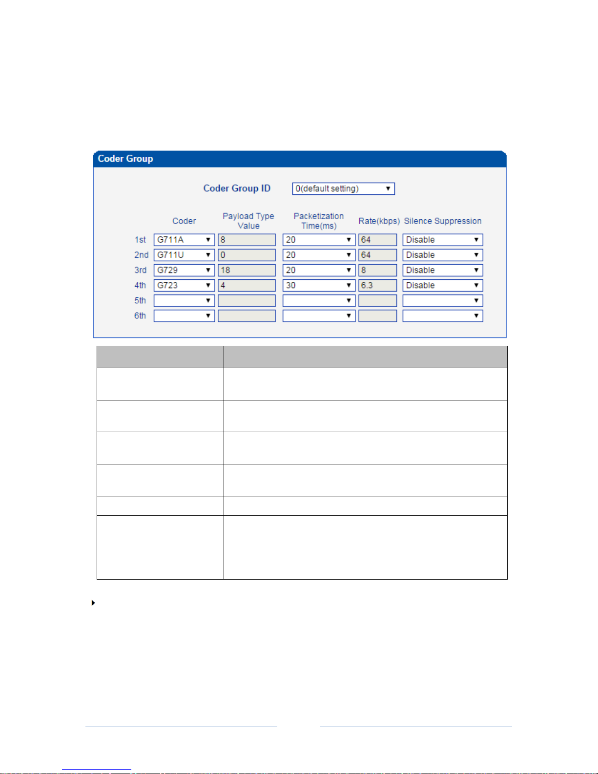
Select the checkbox on the left of an E1/T1 port, and click the Modify button to modify E1/T1 parameters.
Parameter
Explanation
Port No.
The No. of each E1/T1 port
Work Mode
E1 or T1
If E1 is selected for one port, the work modes of all ports are E1.
PCM Mode
PCMA(A LAW) or PCMU(Mu LAW)
If A LAW is selected for one port, the work modes of all ports are A LAW.
Frame Format:
DF
CRC-4
CRC4_ITU
Frame formats of E1 port include DF, CRC-4, CRC4_ITU, and the default
value is CRC-4;
Frame formats of T1 port include F12, F4, ESF, F72, and the default value is
F4.
Line Code
Line codes of E1 include NRZ, CMI, AMI, HDB3, and the default value is
HDB3;
Line codes of T1 include NRZ, CMI, AMI, B8ZS, and the default value is
B8ZS.
Line Built-out
Short Haul (-10DB)
Batch Configure
If Disable is selected, E1/T1 parameter cannot be configured at batch;
If Enable selected, E1/T1 parameter can be configured at batch;
Page 44
MTG3000 VoIP Trunk Gateway User Manual
38
Copyright @ 2011-2016 Dinstar
4.9.3 Codec Group
On the Codec Group interface, you can group several voice codecs together, so when one voice codec is
faulty, another voice codec in the same group can be used. Except codec group 0, the parameters of other
codec groups can be modified.
Parameter
Explanation
Codec Group ID
ID of each codec group for voice ability, from 0 to 7.
The codec group 0 is default setting which cannot be modified.
Codec
MTG3000 supports three kinds of voice codec: G711A, G711U,
G729, G723, iLBC 13k and iLBC 15k.
Payload Type Value
Each codec has a unique payload type value (make reference to
RFC3551).
Packetization Time (ms)
The minimum packetization time of voice codec. For example, if
packetization time is 20ms, voice will be packetized every 30ms.
Rate (kbps)
Transmission rate of voice
Silence Suppression
If silence suppression is enabled, the bandwidth occupied by voice
transmission will be released automatically for the silence party or
when talking is paused.
Default value is ‘Disable’.
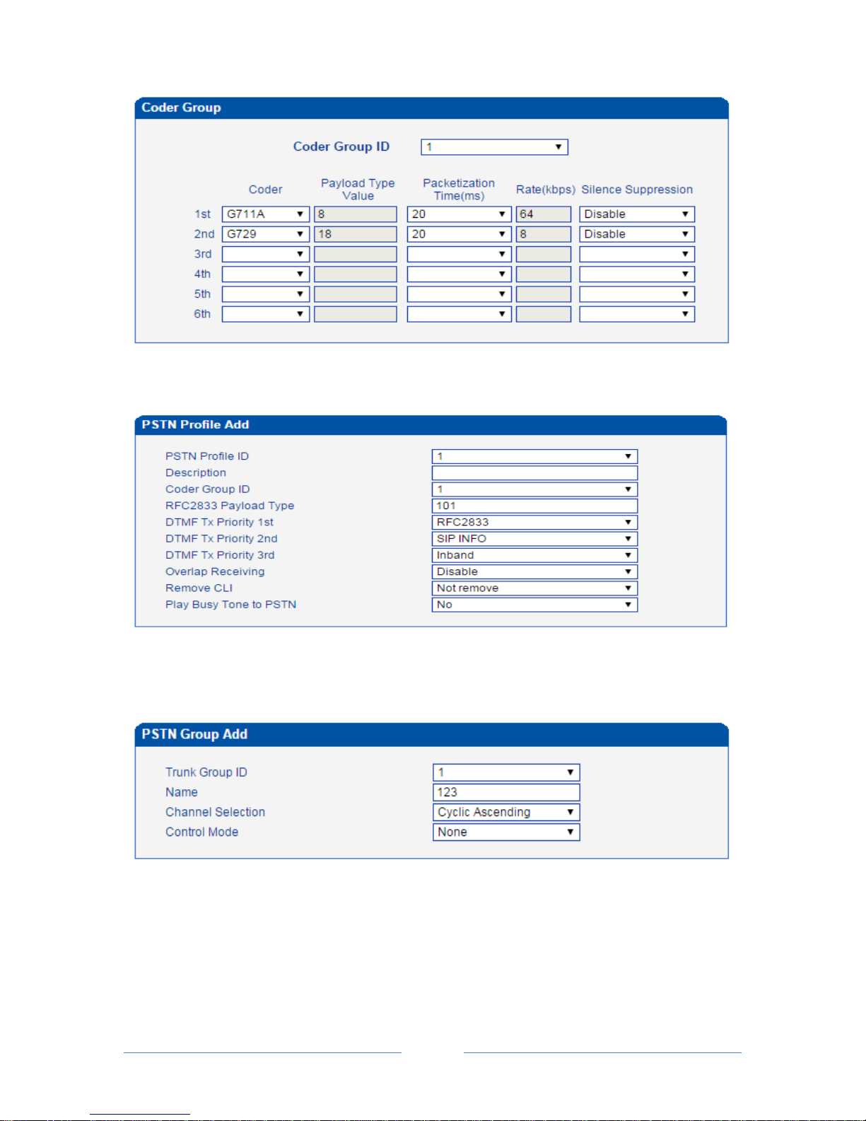
Example: How to configure preferred codec group
Step1. Enter into the Codec Group interface and select codec group ID 1 to create new codec group
Step2. Select preferred voice codec (G711A and G729) in this example, as below:
Page 45
MTG3000 VoIP Trunk Gateway User Manual
39
Copyright @ 2011-2016 Dinstar
Step3. Enter into the PSTN Profile interface, click Modify to modify the default PSTN profile and change
the codec group ID, or click Add to add a new PSTN profile.
Step4. Click OK to save the above configuration.
Step5. Enter into the PSTN Group interface to establish a PSTN group.
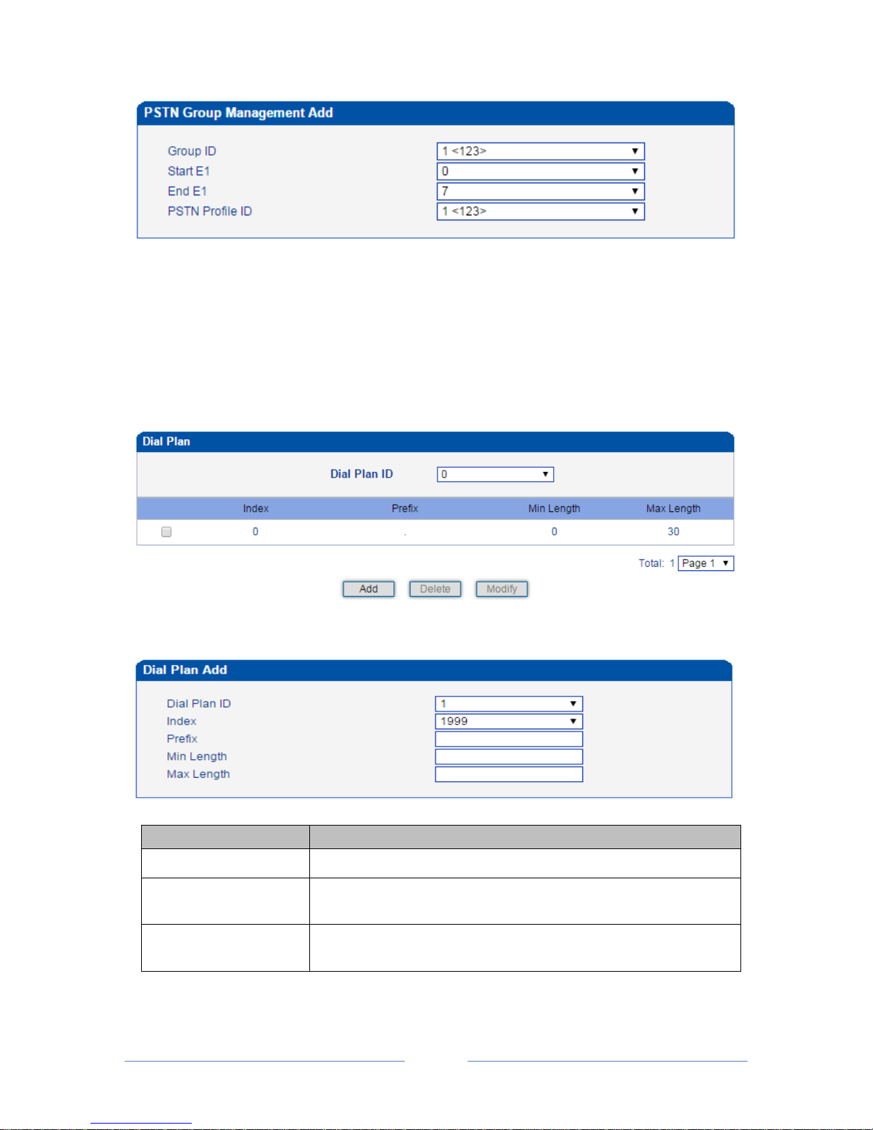
Step6. Enter into the PSTN Group Management interface to associate the PSTN profile and PSTN
group to an E1/T1 port or multiple E1/T1 ports.
Page 46
MTG3000 VoIP Trunk Gateway User Manual
40
Copyright @ 2011-2016 Dinstar
Step7. Click OK save the above configuration.
4.9.4 Dial Plan
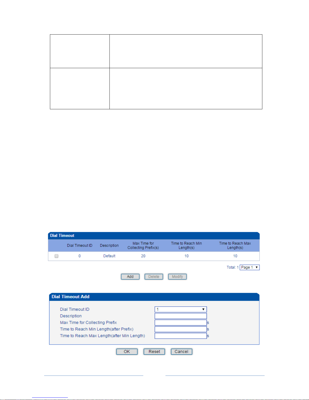
Dial plan is used for the MTG3000 to identify how many digits that a received number includes. Dial rules
can be divided into 5 groups with dial plan IDs. The setting in dial plan 0 is the default setting.
Click the Add button, and you can add a new dial plan in the following interface.
Parameter
Explanation
Dial Plan ID
The ID of the dial plan
Index
Each dial plan has a unique index. Greater index value, higher priority for
the dial plan.
Prefix
The prefix matching received numbers, through which the MTG3000 can
judge how many digits the received number includes.
Page 47
MTG3000 VoIP Trunk Gateway User Manual
41
Copyright @ 2011-2016 Dinstar
Min Length
The minimum number of digits included in a telephone number
(generally from 0 to 30). If the length of a received number falls within
the range of between the set minimum length and the set maximum
length, call connection will continue.
Max Length
The maximum number of digits included in a telephone number
(generally from 0 to 30). If the length of a received number reaches the
set maximum length, MTG3000 deems that all digits of the number have
been received and will begin to analyze the telephone number, and if
there are still digits being sent, MTG3000 will not received them.
Note:
1. Dial plans can be backed up and restored at the Maintenance Data Backup interface and the
Maintenance Data Restore interface respectively.
2. ‘Min Length’ and ‘Max Length’ does not include the length of prefix.
3. For overlapping dialing, it’d better to set ‘Min Length’ and ‘Max Length’ to a same value in order to
accelerate connection rate, since the length of the called number has been known.
4.9.5 Dial Timeout
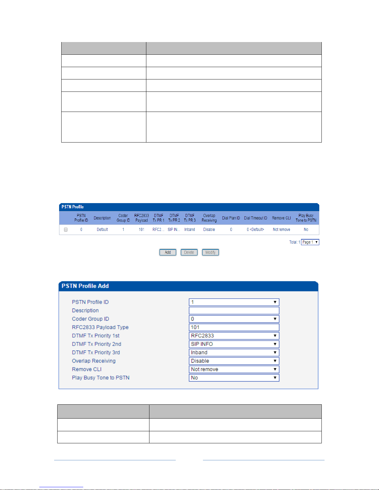
On the Dial Timeout interface, you can set the maximum time for collecting prefix and the maximum time
for telephone number to reach ‘Min Length’ and ‘Max Length’.
The setting in Dial Timeout 0 is default setting, which can be modified but cannot be deleted.
Click the Add button to add a new dial timeout rule.
Page 48
MTG3000 VoIP Trunk Gateway User Manual
42
Copyright @ 2011-2016 Dinstar
Parameter
Explanation
Dial Timeout ID
The ID of the dial timeout
Description
Description of the dial timeout
Max Time for Collecting Prefix
The maximum time for receiving all the digits of a prefix
Time to Reach Min Length
(after Prefix)
After receiving the prefix, the maximum time before receiving the
set minimum number of digits included in a telephone number.
Time to Reach Max Length
(after Min Length)
After receiving the set minimum number of digits, the maximum
time before receiving the set maximum number of digits included in
a telephone number.
4.9.6 PSTN Profile
On the PSTN Profile interface, you can configure PSTN call number rules and related parameters, such as
associating a codec group, a dial plan and a dial timeout to a PSTN profile.
Click the Add button to add a new PSTN profile.
Parameter
Explanation
PSTN Profile ID
The ID of the PSTN profile
Description
The description of the PSTN profile
Page 49
MTG3000 VoIP Trunk Gateway User Manual
43
Copyright @ 2011-2016 Dinstar
Coder Group ID
The ID of the coder group (the coder group needs to be created at
the Coder Group interface first.)
RFC2833 Payload
Default value is 101.
DTMF Tx Priority 1st
There are three ways to send DTMF: RFC2833, SIP INFOR and
Inband. You can set their priority. Priority 1
st
represents the top
priority.
DTMF Tx Priority 2nd
There are three ways to send DTMF: RFC2833, SIP INFOR and
Inband. You can set their priority. Priority 2
st
represents the second
priority.
DTMF Tx Priority 3rd
There are three ways to send DTMF: RFC2833, SIP INFOR and
Inband. You can set their priority. Priority 2
st
represents the third
priority.
Overlap Receiving
Default value is ‘Disable’;
If overlap receiving is enabled, the set ‘Dial Plan’ and ‘Dial
Timeout’ will work.
Remove CLI
CLI: Calling Line Identification
Whether to remove CLI
Play busy tone to PSTN
If ‘Yes’ is selected, when the called phone is offhook, MTG3000
will play busy tone to the PSTN side.
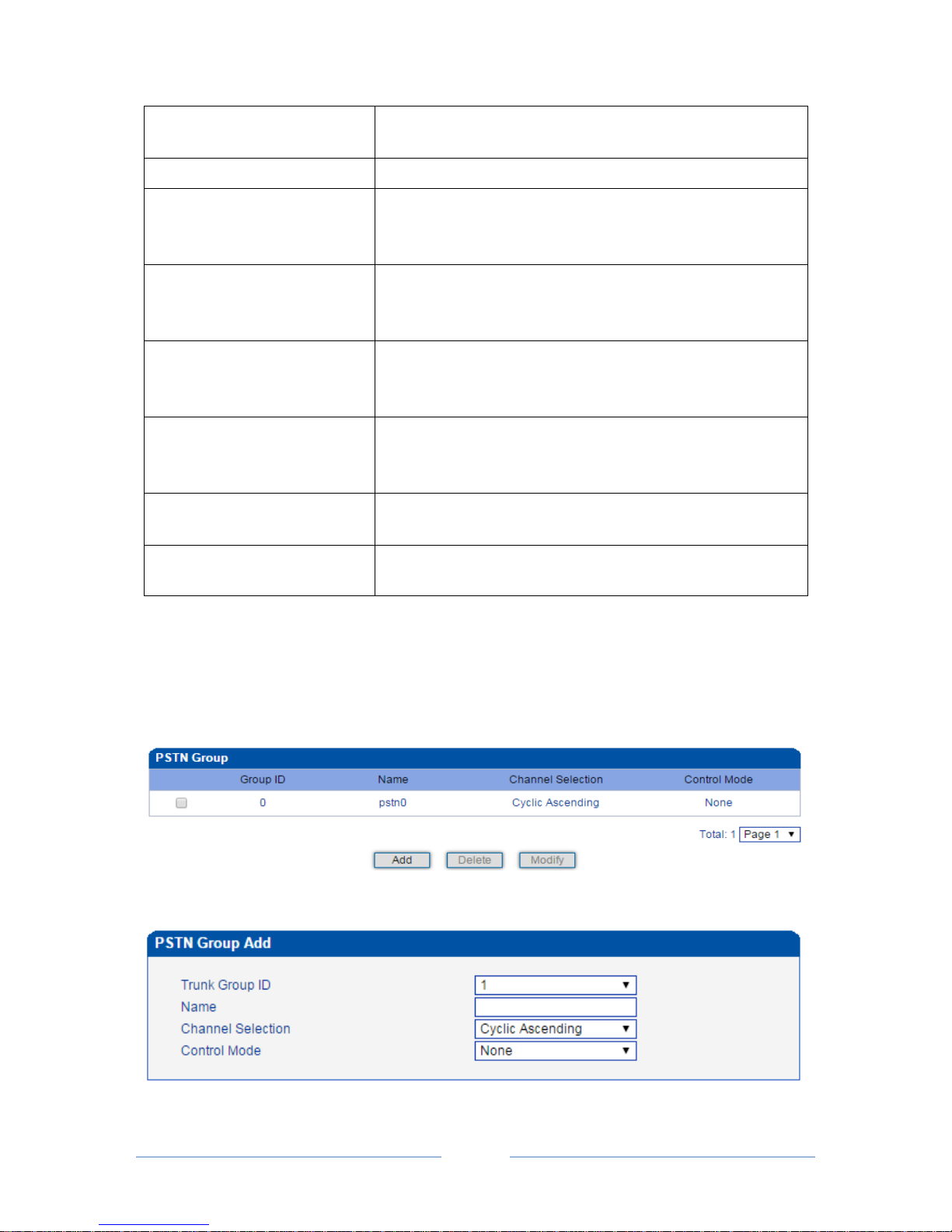
4.9.7 PSTN Group
On the PSTN Group interface, you can create a PSTN group and set a strategy for channel selection of the
group.
Click the Add button to add a new PSTN group.
Page 50
MTG3000 VoIP Trunk Gateway User Manual
44
Copyright @ 2011-2016 Dinstar
Parameter
Explanation
Trunk Group ID
The ID of the trunk group
Name
The name of the trunk group
Channel Selection
There are four selection strategies: Ascending, Descending, Cyclic
Ascending and Cyclic Descending.
Ascending: to search idle channels starting from channel 0 to channel
31;
Cyclic ascending: to search idle channel in an ascending order,
starting from the previous idle channel that has been selected
Control Mode
Control mode is also a method for channel selection and works
together with the set selection strategy.
Options include Master Odd, Master Even and None.
Master Odd: it means channels with odd ID will be searched first, and
channels with even ID will not be searched until all channels with odd
ID have been searched.
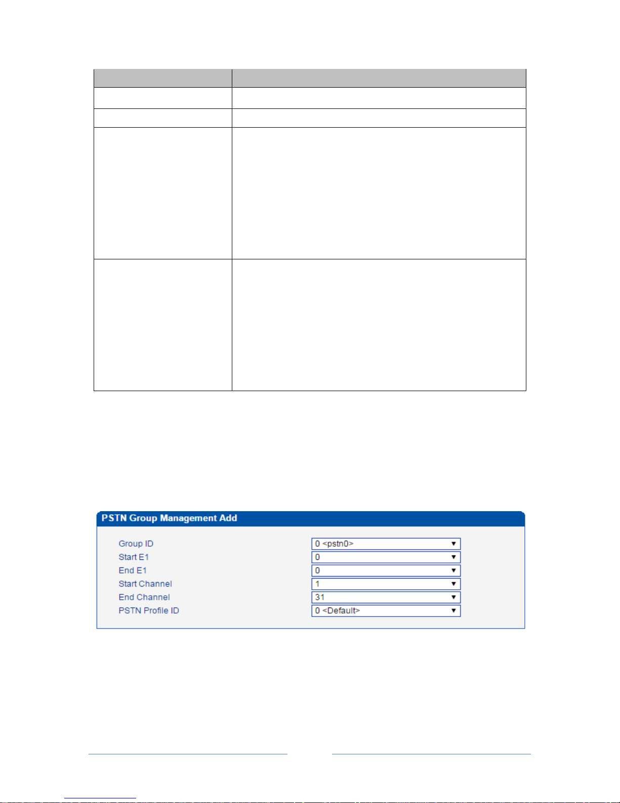
4.9.8 PSTN Group Management
On the PSTN Group Management interface, you can add start E1/T1 port, end E1 /T1 port, start channel,
end channel and PSTN profile to a PSTN group.
Click the Add button, and you will see the following configuration interface.
In the above figure, as start E1 is the same with end E1, only one E1 port is used in the PSTN group and
you need to set start channel and end channel.
When there is a need to set several E1 ports, it defaults that all the 32 channels of each E1 port are used by
the PSTN group.
Page 51
MTG3000 VoIP Trunk Gateway User Manual
45
Copyright @ 2011-2016 Dinstar
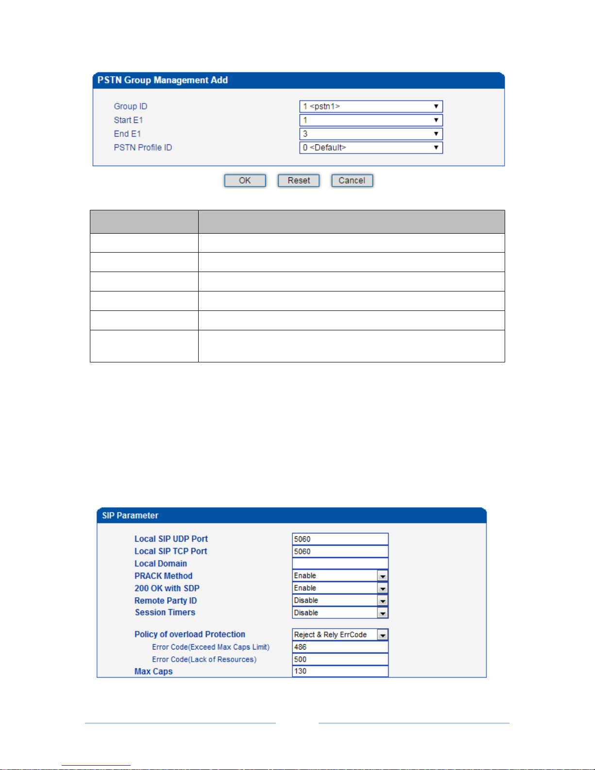
Parameter
Explanation
Group ID
The ID of the PSTN group
Start E1/T1
The start E1/T1 port in this PSTN group
End E1/T1
The end E1/T1 port in this PSTN group
Start Channel
The start channel in this PSTN group
End Channel
The end channel in this PSTN group
PSTN Profile ID
The ID of the PSTN profile in this PSTN group (the PSTN profile needs to
be created at the PSTN Profile interface first.
Note: When the start E1/T1 port is different from the end E1/T1 port, the start channel is channel 0 by
default and the end channel is channel 31 by default (it means there is no need to choose a start channel and
an end channel).
4.10 SIP Config
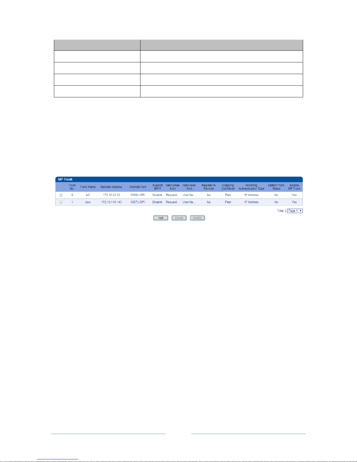
4.10.1 SIP Parameter
Page 52
MTG3000 VoIP Trunk Gateway User Manual
46
Copyright @ 2011-2016 Dinstar
Parameter
Explanation
Local SIP UDP Port
5060 (default)
Local SIP TCP Port
5060 (default)
Local Domain
A local domain whose format is www.xxx.com
PRACK Method
PRACK: Provisional Response ACKnowledgement
4.10.2 SIP Trunk
SIP trunk can realize the connection between MTG3000 and PBX or SIP servers under the IP network. It
provides two modes to connect MTG3000 and the IP network. One is Access (MTG3000 registers to a
softswitch), and the other is Peer (MTG3000 connects to a peer device in the IP network via IP address).
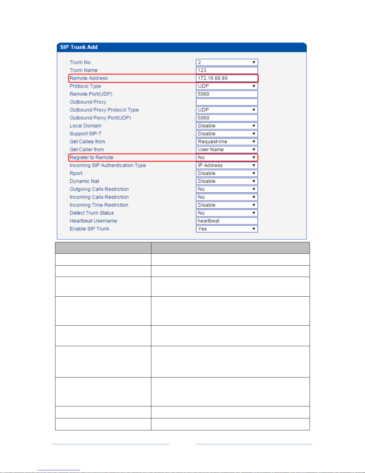
Configuration procedures for Peer Mode are as follows:
1. Click the Add button to add a SIP trunk.
2. Configure parameters on the SIP Trunk Add interface according to related explanations in the table.
As it is Peer mode, you should select No for the Register to Remote parameter, and enter the IP address of
the peer device.
3. After finishing the configuration of the parameters, click OK.
Page 53
MTG3000 VoIP Trunk Gateway User Manual
47
Copyright @ 2011-2016 Dinstar
Parameter
Explanation
Trunk No.
The No. of the SIP trunk (range is 1 ~99)
Trunk Name
The name of the SIP trunk
Remote Address
The IP address of the peer device interfacing with the
MTG3000
Protocol Type
Options include UDP, TCP and Auto
If Auto is selected, the protocol type is determined by the peer
device.
Remote Port (UDP)
The SIP port of the peer device interfacing with the MTG3000;
The default remote port is 5060.
Outbound Proxy IP address
SIP proxy IP address
If outbound proxy is used, enter the IP address or domain name
of the proxy server
Outbound Proxy Protocol Type
Options include UDP, TCP and Auto
If Auto is selected, the protocol type is determined by the peer
device.
Outbound Proxy Port (UDP)
The default outbound proxy port is 5060.
Local Domain
The local domain set in the SIP Parameter interface
Page 54

MTG3000 VoIP Trunk Gateway User Manual
48
Copyright @ 2011-2016 Dinstar
Support SIP-T
This parameter is for SS7. Its default value is ‘Disable’.
Get Callee from
Get the called number from ‘Request-line’ or ‘To Header Field’
Get Caller from
Get the caller number from ‘User Name’ or ‘Display Name’
Register to Remote
It is defined by IETF RFC3372, which is a standard used to
establish remote communication between SIP and ISUP;
The default value is ‘Yes’.
If ‘Yes’ is selected, MTG3000 will be registered to the peer
device whose IP address is filled in ‘Remote Address’.
Incoming SIP Authentication Type
Incoming calls from IP network can be authenticated by IP
address or password. If password is selected, you need fill in
password. If IP address is selected, incoming calls will be
rejected when their IP address are different from the remote
address filled in.
Rport
Whether to enable the Rport of the SIP trunk
Dynamic Nat
Enable or Disable
If it is enabled, a private IP address can be mapped to a public
address from a pool of public IP addresses.
Outgoing Calls Registration
Whether to limit the number of the calls from PSTN to IP
network.
The default value is ‘No’.
If ‘Yes’ is selected, then input the number of concurrent calls
that are allowed to go out. The range is 0 to 65535.
Incoming Calls Registration
Whether to limit the number of the calls from IP network to
PSTN.
The default value is ‘No’.
If ‘Yes’ is selected, then input the number of concurrent calls
that are allowed to come in. The range is 0 to 65535.
Incoming Time Registration
The default setting is ‘Disabled’.
If ‘Enabled’ is selected, user can edit the start and stop time of a
prohibition period. During this period, all calls from IP network
to PSTN are prohibited. (Calls from PSTN to IP network are not
limited)
Detect Trunk Status
Whether to detect the status of the SIP trunk. If ‘Yes’ is selected,
MTG3000 will send Heartbeat message to the peer device to
confirm whether the link status is OK.
Heartbeat Username
The name of the Heartbeat message
Enable SIP Trunk
Whether to enable the SIP trunk.
If ‘Yes’ is selected, the SIP trunk is available;
If ‘No’ is selected, the SIP Trunk is invalid.
Page 55
MTG3000 VoIP Trunk Gateway User Manual
49
Copyright @ 2011-2016 Dinstar
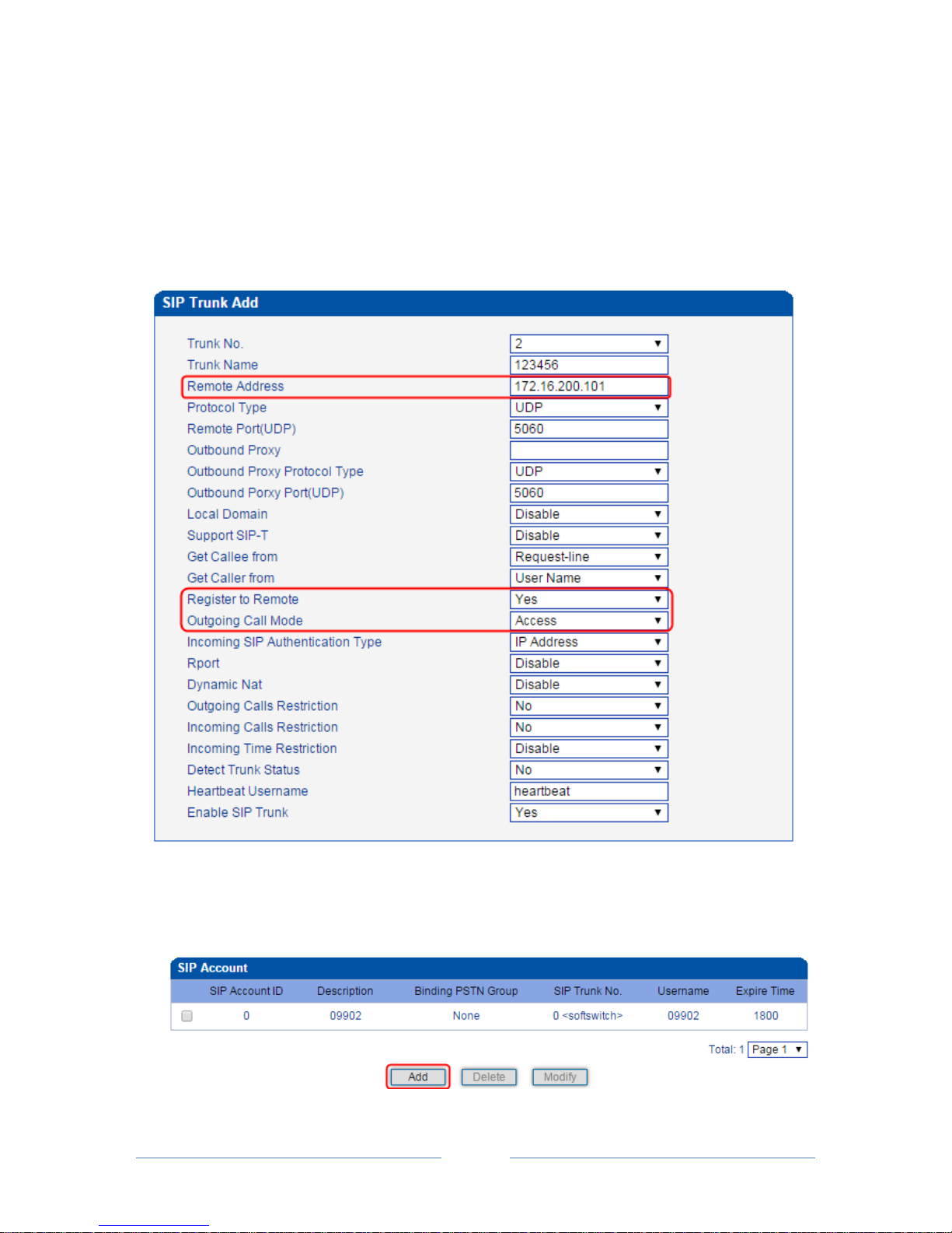
Configuration procedures for Access Mode are as follows:
1. Click the Add button to add a SIP trunk.
2. Configure parameters on the following interface according to related explanations.
As it is Access mode, you should select Yes for the Register to Remote parameter, and enter the IP
address of a softswitch.
3. Click OK.
4. Click SIP Account in the navigation tree on the left, and then click Add to add a SIP account.
Page 56
MTG3000 VoIP Trunk Gateway User Manual
50
Copyright @ 2011-2016 Dinstar
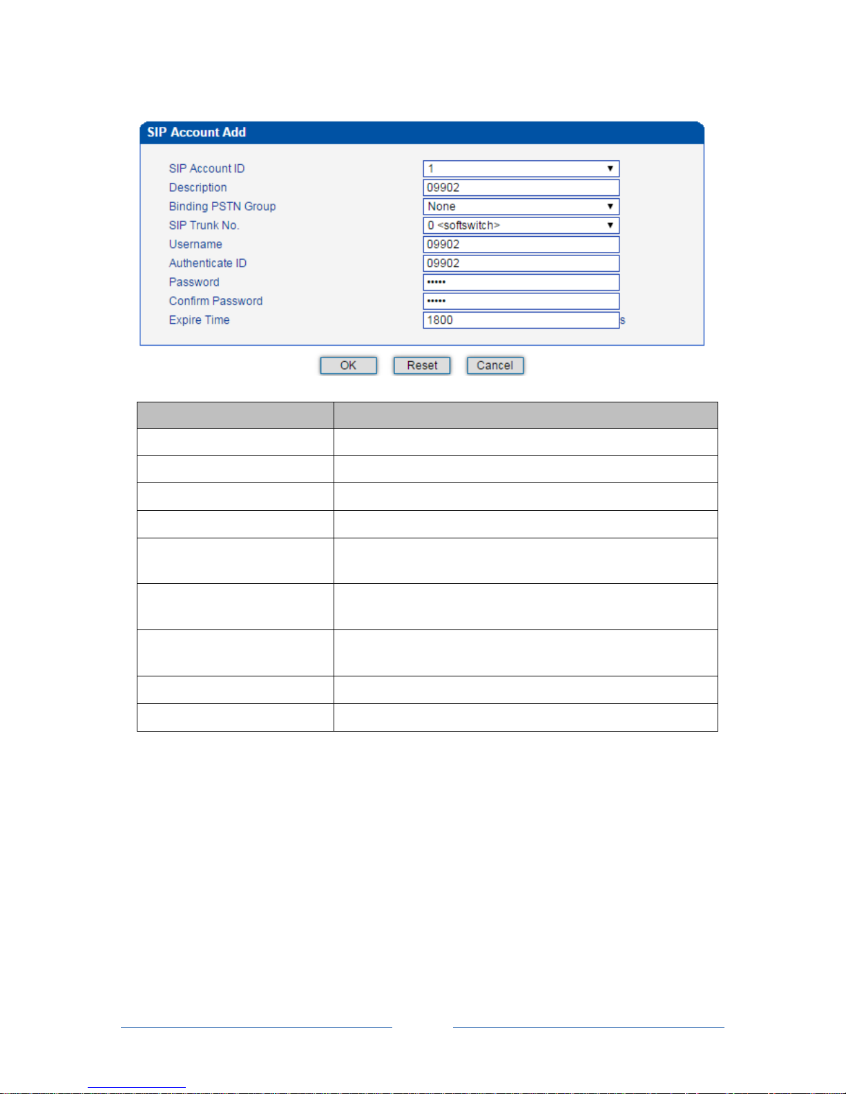
5. Configure the parameters on the SIP Account Add interface.
Parameter
Explanation
SIP Account ID
The ID of SIP Account, from 0 to 127
Description
Description of the SIP account
Binding PSTN Group
Choose a PSTN group that is bound to the SIP account
SIP Trunk No.
The No. of the SIP trunk bound to the SIP account
Username
The username of the SIP account, which is used to register the SIP
account to softswitch
Authenticate ID
The authentication ID to authenticate the SIP account for the
softswitch connected to MTG3000
Password
The password of SIP account, which is used when the SIP account
is registered to softswitch
Confirm Password
Enter the password again
Expire Time
The interval to register the SIP account; Default value is 1800s.
6. Click OK. And you can click Status & Statistics IP Trunk Status to check the SIP trunk that has
been established.
4.11 IP Group Config
You can group several SIP trunks together, so when one SIP trunk is in an outage, communication can turn
to another SIP trunk in the same group.
4.11.1 IP Profile
On the IP Profile interface, you can configure the parameters about IP calls, such as whether to support
Page 57
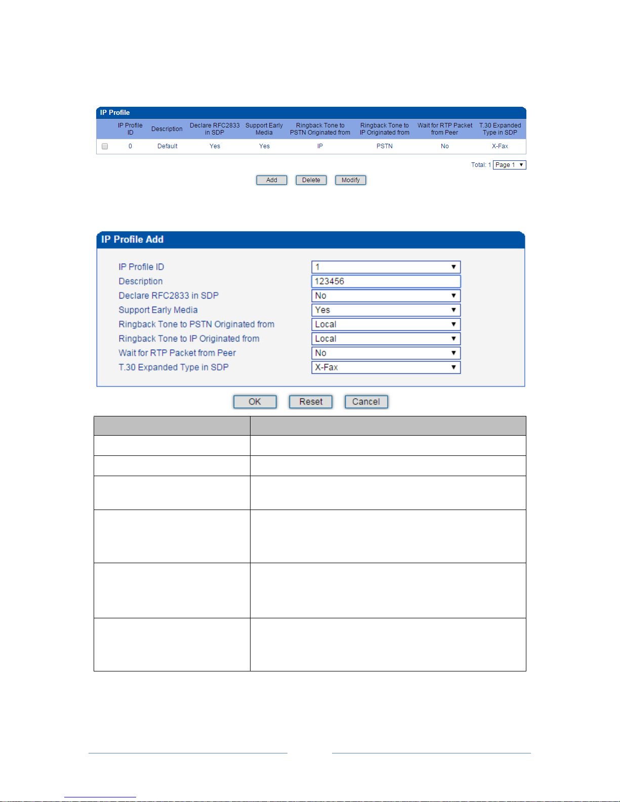
MTG3000 VoIP Trunk Gateway User Manual
51
Copyright @ 2011-2016 Dinstar
early media, where ringback tone to PSTN/IP is originated from and whether to wait for RTP packet from
peer device.
Click Add, and the following interface will be displayed.
Parameter
Explanation
IP Profile ID
The ID of the IP profile, from 1 to 15.
Description
Description of the IP profile
Declare RFC2833 in SDP
Whether to declare RFC2833 in SDP
Default value is ‘Yes’.
Support Early Media
Whether to support Early Media (183)
If ‘Yes’ is selected, ringback tone will be played to the caller
before the call is successfully connected.
Ringback Tone to PSTN Originated
from
Where the ringback tone to PSTN side is originated from
If ‘Local’ is selected, the ringback tone is played from MTG3000.
If ‘IP’ is selected, the ringback tone is played from the IP network
Ringback Tone to IP Originated
from
Where the ringback tone to IP network l is originated from
If ‘Local’ is selected, the ringback tone is played from MTG3000.
If ‘PSTN’ is selected, the ringback tone is played from the PSTN
Page 58
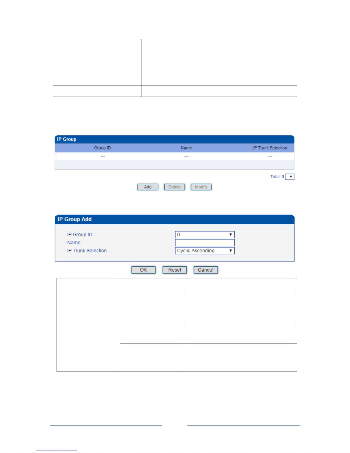
MTG3000 VoIP Trunk Gateway User Manual
52
Copyright @ 2011-2016 Dinstar
Wait for RTP Packet from Peer
If ‘Yes’ is selected, RTP packets will be sent from peer device to
MTG200 first, and then RTP packets will be sent from MTG to
peer device.
If ‘No’ is selected, RTP packets will be sent automatically during
calling;
T.30 Expanded Type in SDP
There are two T.30 expanded types: X-Fax and Fax
4.11.2 IP Group
On the IP Group interface, you can add IP groups and choose a strategy for selecting IP trunks.
Click Add, and the following interface will be displayed.
IP Trunk Selection
Ascending
To select IP trunks in an ascending order under
a same group.
Cyclic Ascending:
To select IP trunks in an ascending order,
starting from the previous IP trunk that has
been selected
Descending
To select IP trunks in a descending order under
a same group
Cyclic Descending
To select IP trunks in a descending order,
starting from the previous IP trunk that has
been selected
4.11.3 IP Group Management
On the IP Group Management interface, you can add IP trunks to the IP group which have been
Page 59
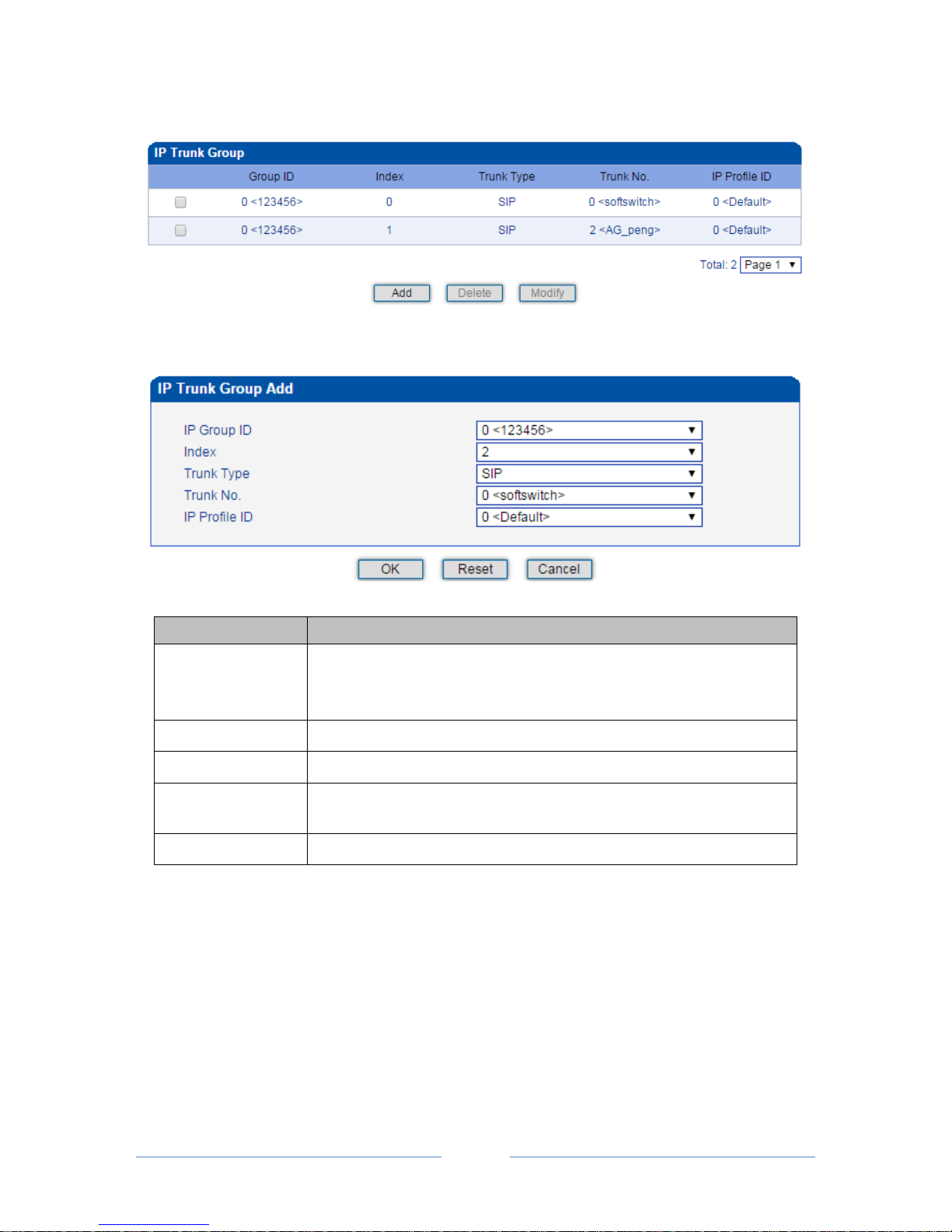
MTG3000 VoIP Trunk Gateway User Manual
53
Copyright @ 2011-2016 Dinstar
established on IP Group interface.
Click Add, and you can see the following interface.
Parameter
Explanation
IP Group ID
The ID of the IP group
If you want to add more IP trunks to the IP group, do not change the IP
group ID.
Index
The index of the IP trunk added to the IP group
Trunk Type
SIP
Trunk No.
Select an IP trunk that has been established on SIP Config SIP Trunk
interface.
IP Profile ID
The ID of the IP profile that will be used by the IP trunk.
4.12 Number Filter
This section is mainly to introduce how to configure white & black lists on the MTG3000 gateway.
Caller White List: Calls from the numbers on the Caller White List will be allowed to pass. If a caller
number cannot match with one of the numbers on the Caller White List, calls from the caller number will
be rejected.
Page 60
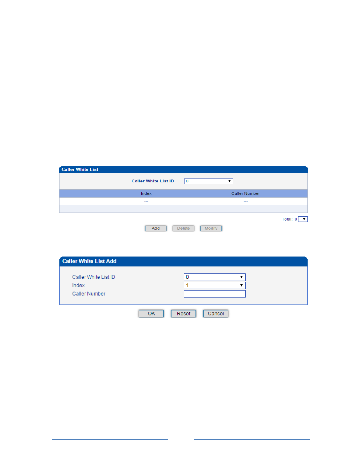
MTG3000 VoIP Trunk Gateway User Manual
54
Copyright @ 2011-2016 Dinstar
Caller Black List: Calls from the numbers on the Caller Black List will be rejected to pass. If a caller
number match with one of the numbers on the Caller Black List, calls will be rejected.
Callee White List: Calls to the numbers on the Callee White List will be allowed to pass. If a callee
number cannot match with one of one of the numbers on the Caller White List, calls to the callee number
will be rejected.
Callee Black List: Calls to the numbers on the Callee Black List will be rejected to pass. If a callee number
match with one of the numbers on the Callee Black List, calls to the callee number will be rejected.
4.12.1 Procedures to add a number on the Caller White List
1. Click Number Filter Caller White List to enter into the following interface.
2. Click Add to enter into the following interface to add a caller number on the Caller White List
3. Choose an ID for the caller white list and an index for the caller number, and then enter the caller
number
4. Click OK.
Note:
You can add 8 white or black lists at most, with ID from 0 to 7. And each white or black list can contain
1024 numbers at most.
Page 61
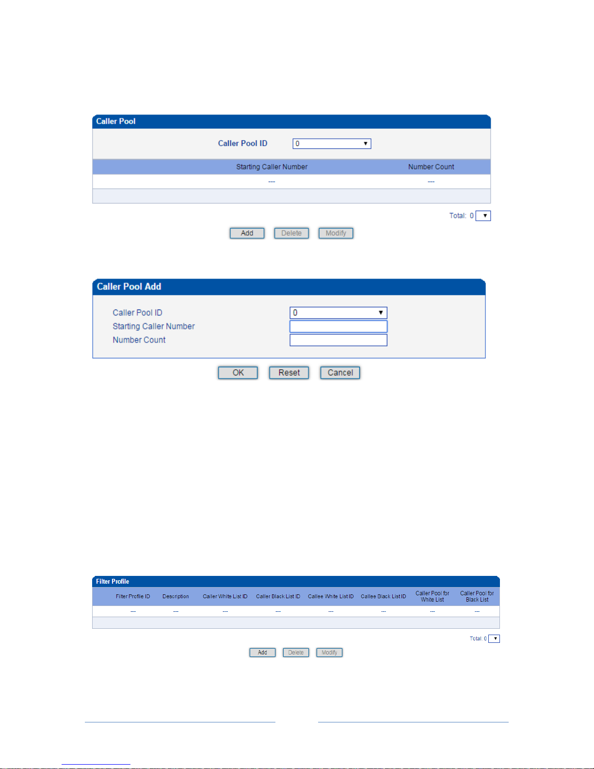
MTG3000 VoIP Trunk Gateway User Manual
55
Copyright @ 2011-2016 Dinstar
4.12.2 Caller Pool
On the Caller Pool interface, you can add a batch of telephone numbers to replace the actual caller
numbers when there is a need.
Click Add to set numbers in the caller pool.
Note:
If ‘Starting Caller Number’ is 80080000 and ‘Number Count’ is 100, it means numbers from 80080000 to
80080099 are all in the caller pool.
Each caller poor can contain 512 numbers at most, and if there are multiple caller pools, the caller pools
can contain up to 1024 numbers in total.
4.12.3 Filter Profile
On the Filter Profile interface, you can put white lists and black lists that have been set before in a filter
profile or several profiles. The white lists and black lists will not take effect until you set them in filter
profiles.
Page 62
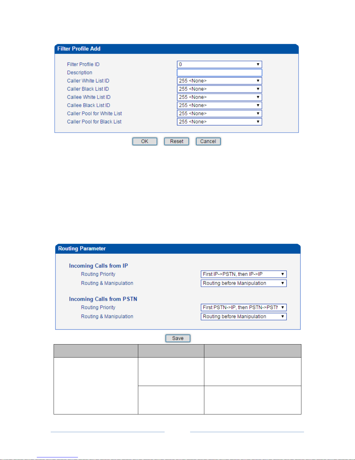
MTG3000 VoIP Trunk Gateway User Manual
56
Copyright @ 2011-2016 Dinstar
Select a white list ID, and the calls of the numbers on the white list will be passed. Select a black list ID,
and the calls of the numbers on the black list will be prohibited.
If you select 255<None>, it means no while lists or black lists are set in filter profile, and no numbers will
be filtered.
4.13 Call Routing
4.13.1 Routing Parameter
Belong To
Parameter
Explanation
Incoming Calls from IP
Routing Priority
There are two options:
First IPPSTN, then IP IP
First IPIP, then IP PSTN
Routing & Manipulation
There are two options:
Routing before Manipulation
Routing after Manipulation
Page 63
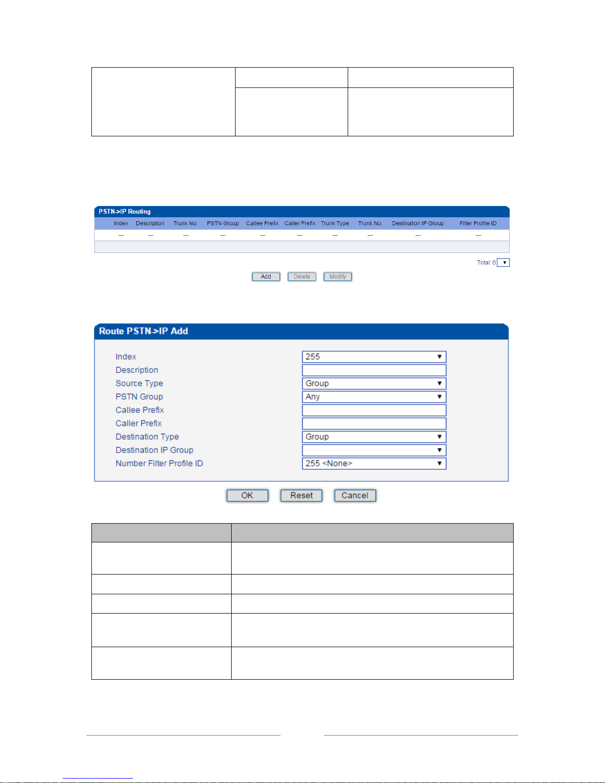
MTG3000 VoIP Trunk Gateway User Manual
57
Copyright @ 2011-2016 Dinstar
Incoming Calls from PSTN
Routing Priority
First PSTN IP, then PSTNPSTN
Routing & Manipulation
There are two options:
Routing before Manipulation
Routing after Manipulation
4.13.2 PSTNIP Routing
On the PSTNIP Routing interface, you can set routing parameters for PSTN IP calls.
Click Add, and the following interface will be displayed.
Parameter
Explanation
Index
The Index of the PSTN IP route, from 0 to 255. Greater index
value, higher priority for the route.
Description
The description of the PSTN IP route,
Source Type
Sources include PSTN group and PRI/SS7 trunk.
PSTN Group
If source is PSTN group, please select a specific PSTN group. If
‘Any’ is selected, it means the source is any PSTN group.
PSTN Trunk
If source is PSTN trunk, please select a specific PRI/SS7 trunk. If
‘Any’ is selected, it means the source is any PRI/SS7 trunk. .
Page 64
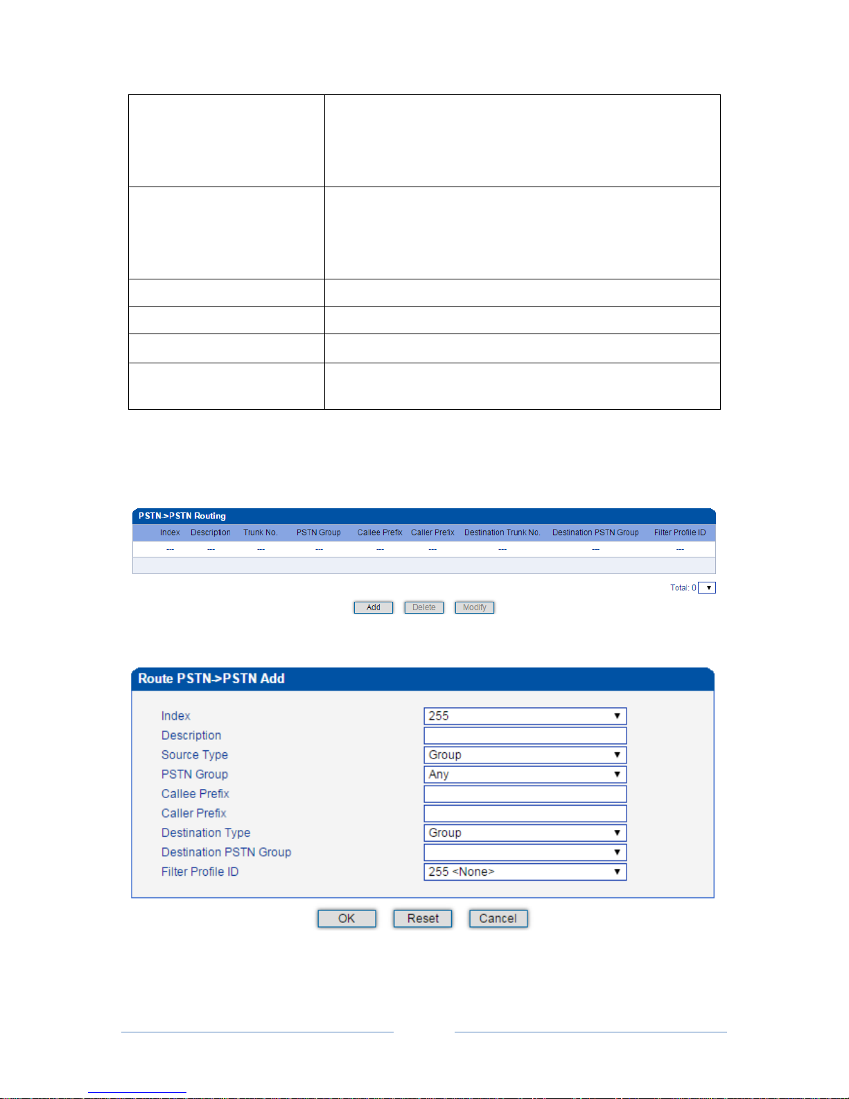
MTG3000 VoIP Trunk Gateway User Manual
58
Copyright @ 2011-2016 Dinstar
Callee Prefix
The prefix configured for callee number. When a callee number
matches the prefix, this PSTN IP route will be used.
‘.’ is a wildcard, which means this PSTN IP route will be used, no
matter what the callee number is.
Caller Prefix
The prefix configured for caller number. When a caller number
matches the prefix, this PSTN IP route will be used.
‘.’ is a wildcard, which means this PSTN IP route will be used, no
matter what the caller number is.
Destination Type
Destination is IP group or SIP trunk.
Destination IP Group
If source is IP group, please select a specific IP group.
IP Trunk No.
If source is SIP trunk, please select a specific IP trunk.
Number Filter Profile ID
The ID of filter profile. The white lists and black lists set in the filter
profile will apply to this PSTN IP route.
4.13.3 PSTN PSTN Routing
On the PSTNPSTN Routing interface, you can set routing parameters for PSTN PSTN calls.
Click Add, and the following interface will be displayed.
Page 65
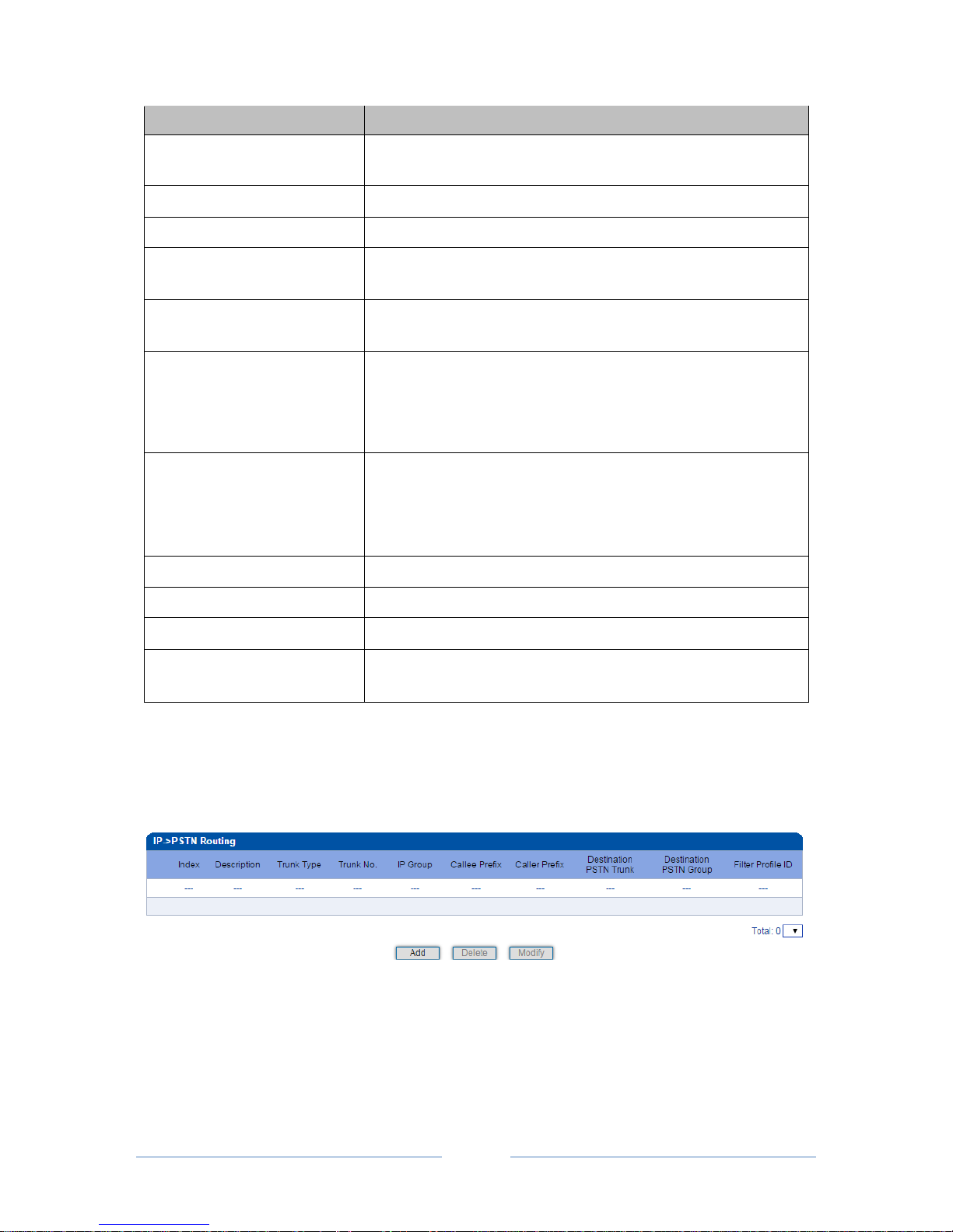
MTG3000 VoIP Trunk Gateway User Manual
59
Copyright @ 2011-2016 Dinstar
Parameter
Explanation
Index
The Index of the PSTN PSTN route, from 0 to 255. Greater index
value, higher priority for the route.
Description
The description of the PSTN PSTN route,
Source Type
Sources include PSTN group and PRI/SS7 trunk.
PSTN Group
If source is PSTN group, please select a specific PSTN group. If
‘Any’ is selected, it means the source is any PSTN group.
PSTN Trunk
If source is PSTN trunk, please select a specific PRI/SS7 trunk. If
‘Any’ is selected, it means the source is any PRI/SS7 trunk. .
Callee Prefix
The prefix configured for callee number. When a callee number
matches the prefix, this PSTN IP route will be used.
‘.’ is a wildcard, which means this PSTN PSTN route will be used,
no matter what the callee number is.
Caller Prefix
The prefix configured for caller number. When a caller number
matches the prefix, this PSTN PSTN route will be used.
‘.’ is a wildcard, which means this PSTN PSTN route will be used,
no matter what the caller number is.
Destination Type
Destination is PSTN group or PRI/SS7 trunk.
Destination IP Group
If source is PSTN group, please select a specific PSTN group.
IP Trunk No.
If source is PRI/SS7 trunk, please select a specific PRI/SS7 trunk.
Number Filter Profile ID
The ID of filter profile. The white lists and black lists set in the filter
profile will apply to this PSTN PSTN route.
4.13.4 IP PSTN Routing
On the PSTNIP Routing interface, you can set routing parameters for IP PSTN calls.
Click Add, and the following interface will be displayed.
Page 66
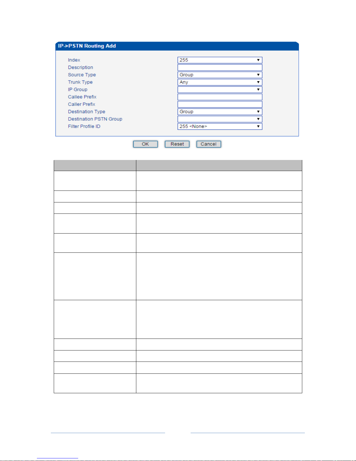
MTG3000 VoIP Trunk Gateway User Manual
60
Copyright @ 2011-2016 Dinstar
Parameter
Explanation
Index
The Index of the IPPSTN route, from 0 to 255. Greater index
value, higher priority for the route.
Description
The description of the IP PSTN route,
Source Type
Sources include IP group and IP trunk.
PSTN Group
If source is IP group, please select a specific IP group. If ‘Any’ is
selected, it means the source is any IP group.
PSTN Trunk
If source is IP trunk, please select a specific SIP trunk. If ‘Any’ is
selected, it means the source is any IP trunk. .
Callee Prefix
The prefix configured for callee number. When a callee number
matches the prefix, this IPPSTN route will be used.
‘.’ is a wildcard, which means this IPPSTN route will be used, no
matter what the callee number is.
Caller Prefix
The prefix configured for caller number. When a caller number
matches the prefix, this IPPSTN route will be used.
‘.’ is a wildcard, which means this IPPSTN route will be used, no
matter what the caller number is.
Destination Type
Destination is PSTN group or PRI/SS7 trunk.
Destination IP Group
If source is PSTN group, please select a specific PSTN group.
IP Trunk No.
If source is PRI/SS7 trunk, please select a specific PRI/SS7 trunk.
Number Filter Profile ID
The ID of filter profile. The white lists and black lists set in the filter
profile will apply to this PSTN PSTN route.
Page 67
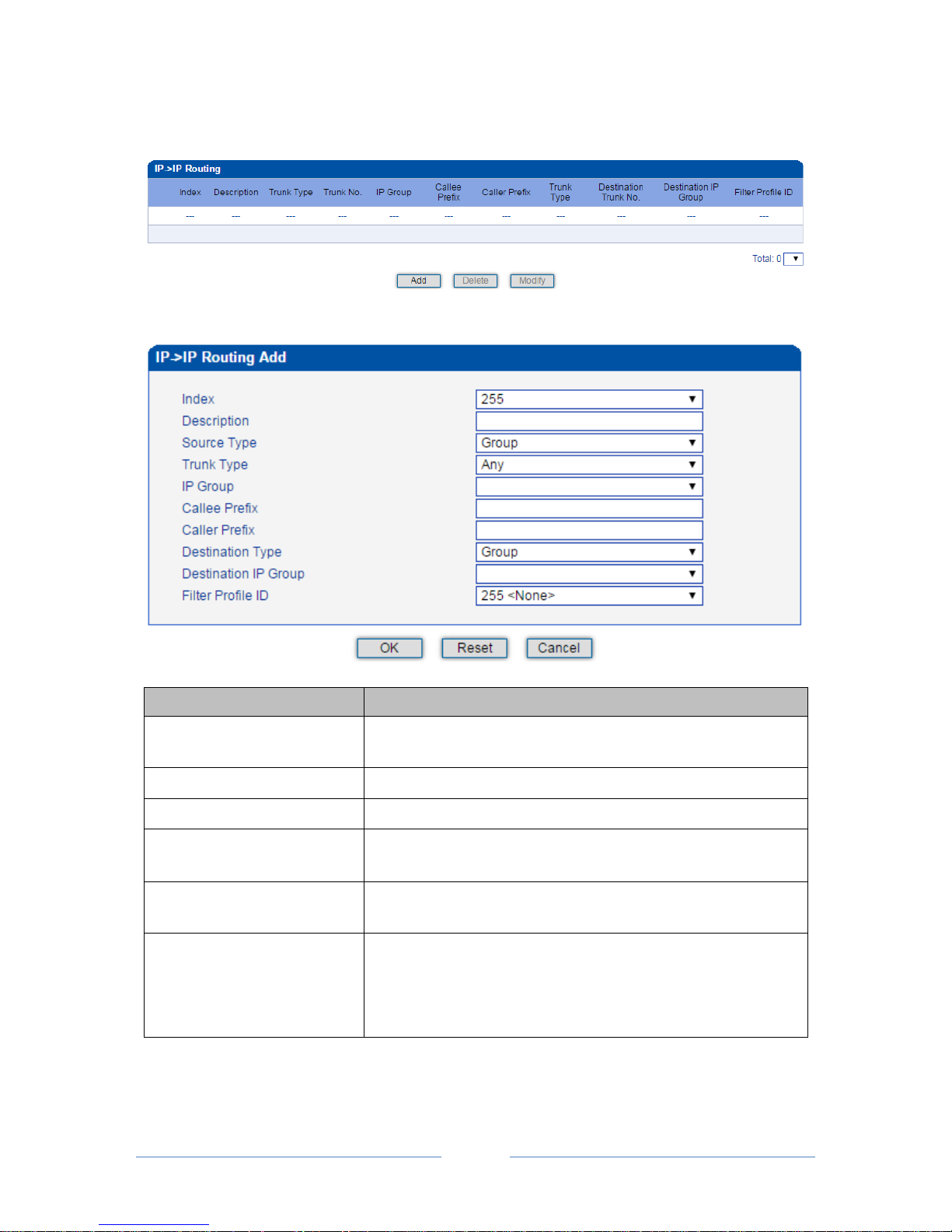
MTG3000 VoIP Trunk Gateway User Manual
61
Copyright @ 2011-2016 Dinstar
4.13.5 IP IP Routing
On the IPIP Routing interface, you can set routing parameters for IP IP calls.
Click Add, and the following interface will be displayed.
Parameter
Explanation
Index
The Index of the IP IP route, from 0 to 255. Greater index value,
higher priority for the route.
Description
The description of the IP IP route,
Source Type
Sources include IP group and IP trunk.
PSTN Group
If source is IP group, please select a specific IP group. If ‘Any’ is
selected, it means the source is any IP group.
PSTN Trunk
If source is IP trunk, please select a specific SIP trunk. If ‘Any’ is
selected, it means the source is any IP trunk. .
Callee Prefix
The prefix configured for callee number. When a callee number
matches the prefix, this IP IP route will be used.
‘.’ is a wildcard, which means this IP IP route will be used, no
matter what the callee number is.
Page 68
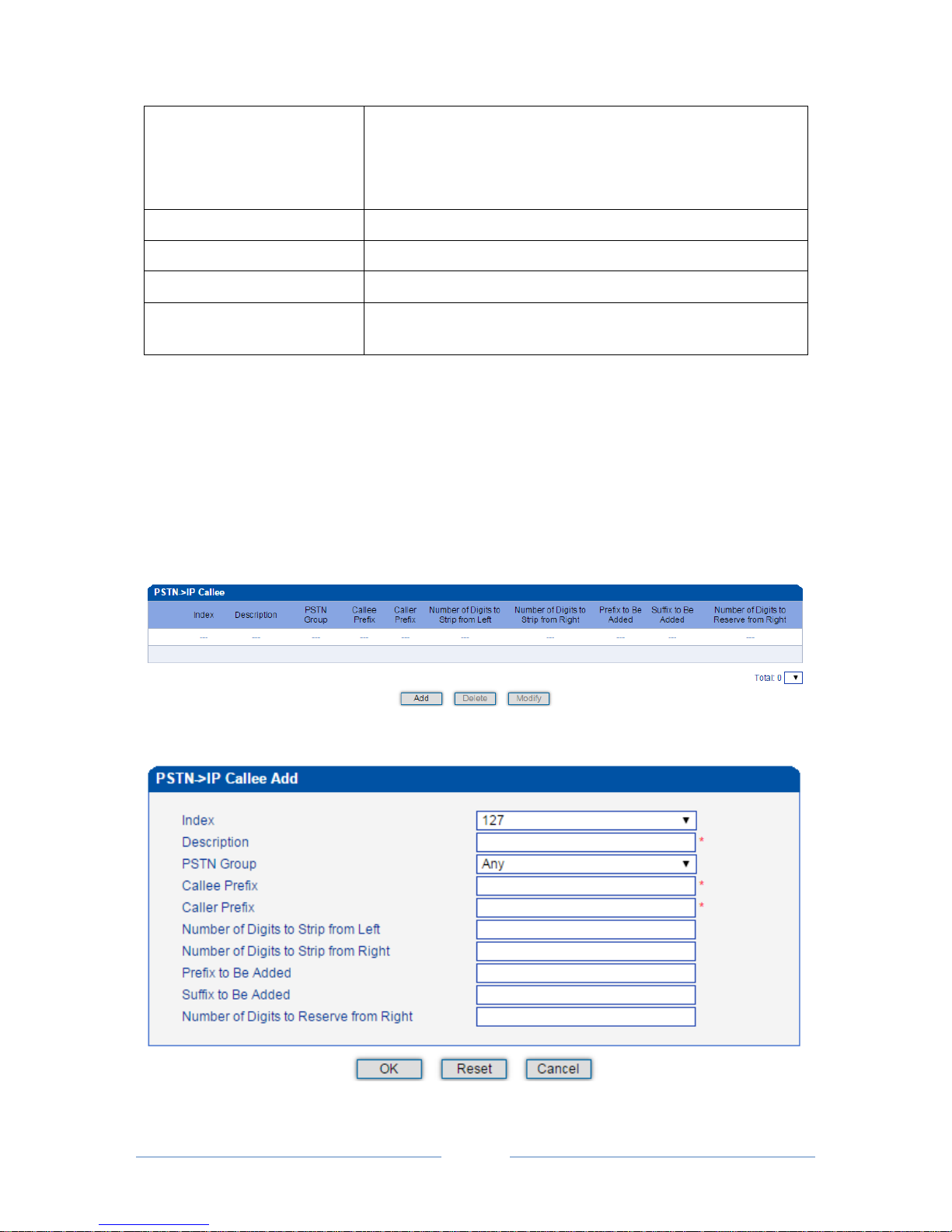
MTG3000 VoIP Trunk Gateway User Manual
62
Copyright @ 2011-2016 Dinstar
Caller Prefix
The prefix configured for caller number. When a caller number
matches the prefix, this IP IP route will be used.
‘.’ is a wildcard, which means this IP IP route will be used, no
matter what the caller number is.
Destination Type
Destination is IP group or SIP trunk.
Destination IP Group
If source is IP group, please select a specific IP group.
IP Trunk No.
If source is SIP trunk, please select a specific PRI/SS7 trunk.
Number Filter Profile ID
The ID of filter profile. The white lists and black lists set in the filter
profile will apply to this IP IP route.
4.14 Number Manipulation
Number manipulation refers to the change of the caller number or callee number during calling process.
4.14.1 PSTN IP Callee
On the PSTN IP Callee interface, you can set rules to change the actual callee number during PSTN
IP calling process.
Click Add, and the following interface will be displayed.
Page 69
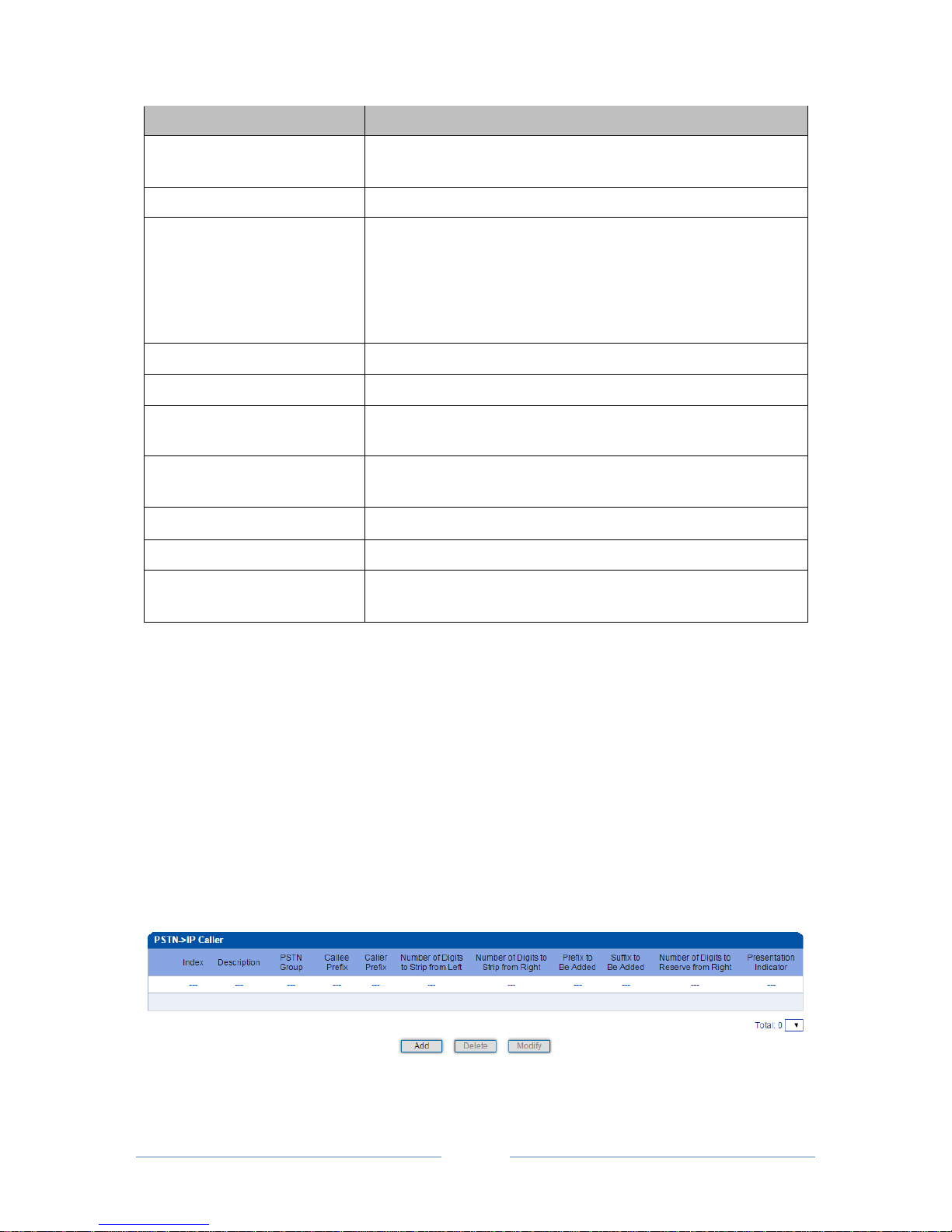
MTG3000 VoIP Trunk Gateway User Manual
63
Copyright @ 2011-2016 Dinstar
Parameter
Explanation
Index
The index of this PSTN IP callee number manipulation, from 0 to
127. Each index cannot be used repeatedly.
Description
The description of this PSTN IP callee number manipulation
PSTN Group
Select a PSTN group. The callee number will be manipulated when a
call uses a trunk of this PSTN group, actual callee prefix matches the
set callee prefix, and actual caller prefix matches the set caller prefix.
‘Any’ means any PSTN group.
Callee Prefix
Set a prefix for the callee number.
Caller Prefix
Set a prefix for the caller number
Number of Digits to Strip from
Left
The number of digits which are lessened from the left of the callee
number
Number of Digits to Strip from
Right
The number of digits which are lessened from the right of the callee
number
Prefix to be added
The prefix added to the callee number after its digits are lessened.
Suffix to be added
The suffix added to the callee number after its digits are lessened.
Number of Digits to Reserve
from Right
The number of the retained digits which. are counted from the right
of the callee number
For example:
If the called number is 25026531014, how do you change it into 026531014 ?
You can enter ‘3’ in the value box for the ‘Number of Digits to Strip from Left’ parameter.
If the called number is 2653101413, how do you change it into 00912653101413?
You can enter ‘ 0091’ in the value box for the ‘Callee Prefix’ parameter.
4.14.2 PSTNIP Caller
On the PSTN IP Caller interface, you can set rules to change the actual caller number during PSTN
IP calling process.
Page 70
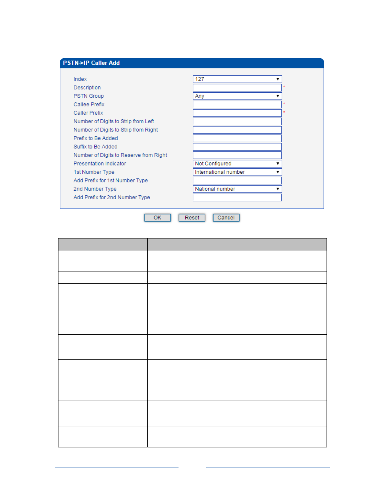
MTG3000 VoIP Trunk Gateway User Manual
64
Copyright @ 2011-2016 Dinstar
Click Add, and the following interface will be displayed.
Parameter
Explanation
Index
The index of this PSTN IP caller number manipulation, from 0 to
127. Each index cannot be used repeatedly.
Description
The description of this PSTN IP caller number manipulation
PSTN Group
Select a PSTN group. The caller number will be manipulated when a
call uses a trunk of this PSTN group, actual callee prefix matches the
set callee prefix, and actual caller prefix matches the set caller prefix.
‘Any’ means any PSTN group.
Callee Prefix
Set a prefix for the callee number.
Caller Prefix
Set a prefix for the caller number
Number of Digits to Strip from
Left
The number of digits which are lessened from the left of the caller
number
Number of Digits to Strip from
Right
The number of digits which are lessened from the right of the caller
number
Prefix to be added
The prefix added to the caller number after its digits are lessened.
Suffix to be added
The suffix added to the caller number after its digits are lessened.
Number of Digits to Reserve
from Right
The number of the retained digits which. are counted from the right
of the caller number
Page 71
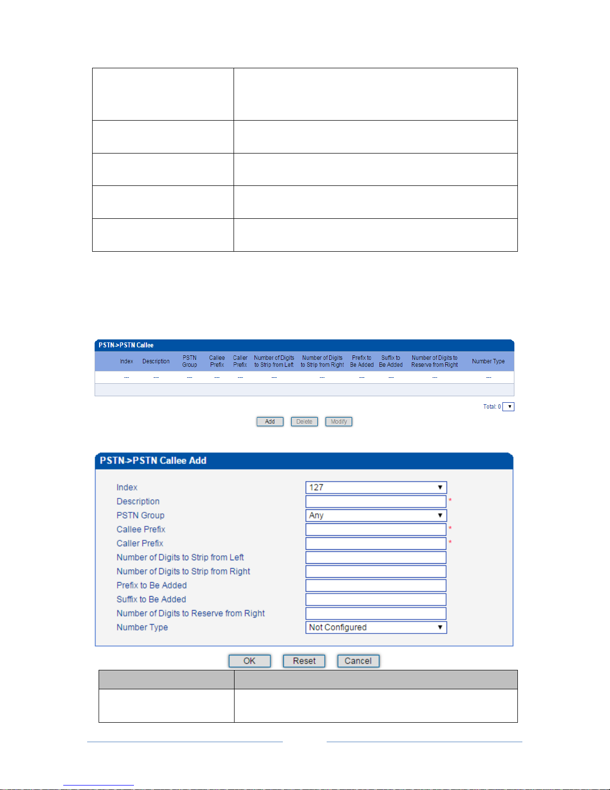
MTG3000 VoIP Trunk Gateway User Manual
65
Copyright @ 2011-2016 Dinstar
Presentation Indicator
If “Allowed” is selected, the calling number will be presented.
If “Restricted” is selected, the calling number will not be presented.
If “Not Config” is selected, the parameter does not work.
1st Number Type
If the caller number belongs to 1st number type, the set prefix will be
added to the caller number.
Add Prefix for 1st Number Type
The prefix that will be added to those numbers that belong to 1st
number type
2nd Number Type
If the caller number belongs to 2
nd
number type, the set prefix will be
added to the caller number.
Add Prefix for 2nd Number Type
The prefix that will be added to those numbers that belong to 2nd
number type
4.14.3 PSTNPSTN Callee
On the PSTN PSTN Callee interface, you can set rules to change the actual callee number during PSTN
PSTN calling process.
Click Add, and the following interface will be displayed.
Parameter
Explanation
Index
The index of this PSTN PSTN callee number manipulation, from
0 to 127. Each index cannot be used repeatedly.
Page 72
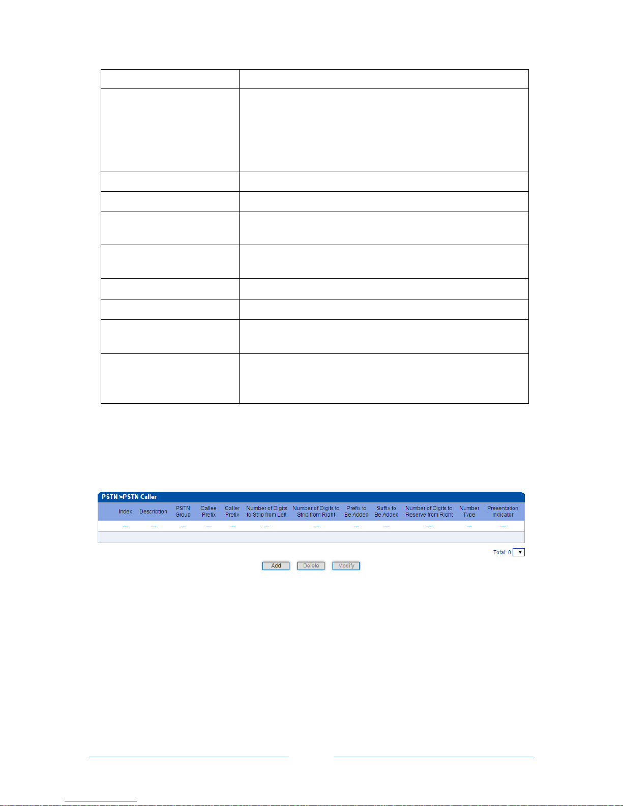
MTG3000 VoIP Trunk Gateway User Manual
66
Copyright @ 2011-2016 Dinstar
Description
The description of this PSTN PSTN callee number manipulation
PSTN Group
Select a PSTN group. The callee number will be manipulated when a
call uses a trunk of this PSTN group, actual callee prefix matches the
set callee prefix, and actual caller prefix matches the set caller prefix.
‘Any’ means any PSTN group.
Callee Prefix
Set a prefix for the callee number.
Caller Prefix
Set a prefix for the caller number
Number of Digits to Strip from
Left
The number of digits which are lessened from the left of the callee
number
Number of Digits to Strip from
Right
The number of digits which are lessened from the right of the callee
number
Prefix to be added
The prefix added to the callee number after its digits are lessened.
Suffix to be added
The suffix added to the callee number after its digits are lessened.
Number of Digits to Reserve
from Right
The number of the retained digits which. are counted from the right
of the callee number
Number Type
The type of the callee number. Options include ‘Not Config’,
‘International’, ‘National’, ‘Unknown’, ‘Network Specific’,
‘Subscriber’ and ‘Abbreviated’
4.14.4 PSTN PSTN Caller
On the PSTN PSTN Caller interface, you can set rules to change the actual caller number during PSTN
PSTN calling process.
Click Add, and the following interface will be displayed.
Page 73
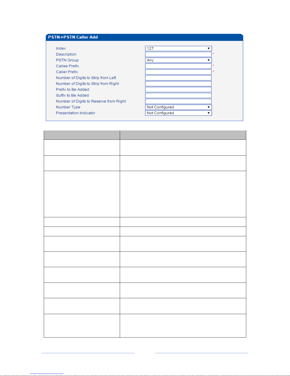
MTG3000 VoIP Trunk Gateway User Manual
67
Copyright @ 2011-2016 Dinstar
Parameter
Explanation
Index
The index of this PSTN PSTN caller number manipulation,
from 0 to 127. Each index cannot be used repeatedly.
Description
The description of this PSTN PSTN caller number
manipulation
PSTN Group
Select a PSTN group. The caller number will be manipulated
when a call uses a trunk of this PSTN group, actual callee prefix
matches the set callee prefix, and actual caller prefix matches
the set caller prefix.
‘Any’ means any PSTN group.
Callee Prefix
Set a prefix for the callee number.
Caller Prefix
Set a prefix for the caller number
Number of Digits to Strip from Left
The number of digits which are lessened from the left of the
caller number
Number of Digits to Strip from Right
The number of digits which are lessened from the right of the
caller number
Prefix to be added
The prefix added to the caller number after its digits are
lessened.
Suffix to be added
The suffix added to the caller number after its digits are
lessened.
Number of Digits to Reserve from
Right
The number of the retained digits which. are counted from the
right of the caller number
Presentation Indicator
If “Allowed” is selected, the calling number will be presented.
If “Restricted” is selected, the calling number will not be
presented.
Page 74
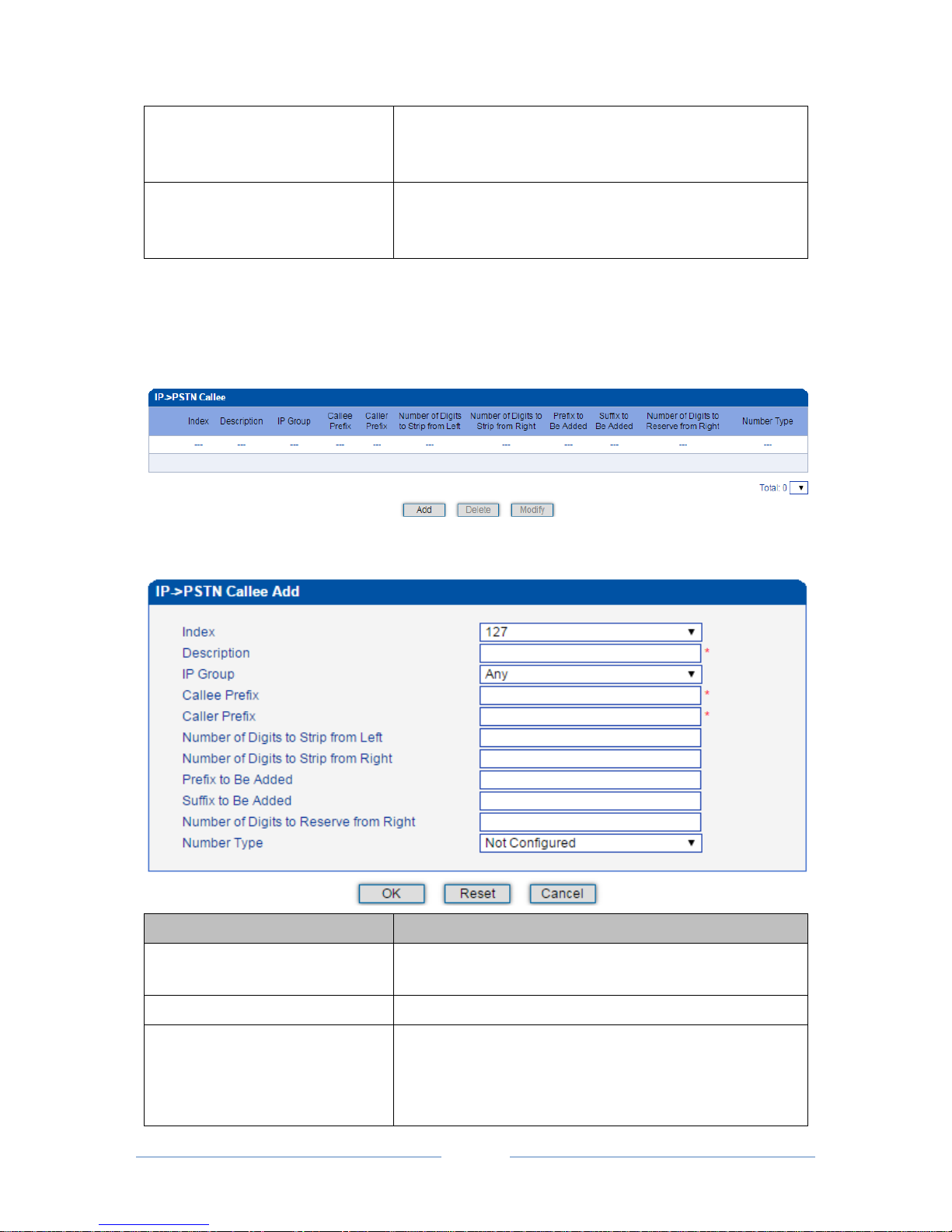
MTG3000 VoIP Trunk Gateway User Manual
68
Copyright @ 2011-2016 Dinstar
If “Not Config” is selected, the parameter does not work.
Number Type
The type of the caller number. Options include ‘Not Config’,
‘International’, ‘National’, ‘Unknown’, ‘Network Specific’,
‘Subscriber’ and ‘Abbreviated’
4.14.5 IPPSTN Callee
On the IP PSTN Callee interface, you can set rules to change the actual callee number during IP
PSTN calling process.
Click Add, and the following interface will be displayed.
Parameter
Explanation
Index
The index of this IP PSTN callee number manipulation, from
0 to 127. Each index cannot be used repeatedly.
Description
The description of this IP PSTN callee number manipulation
IP Group
Select an IP group. The callee number will be manipulated when
a call uses a trunk of this IP group, actual callee prefix matches
the set callee prefix, and actual caller prefix matches the set
caller prefix.
Page 75
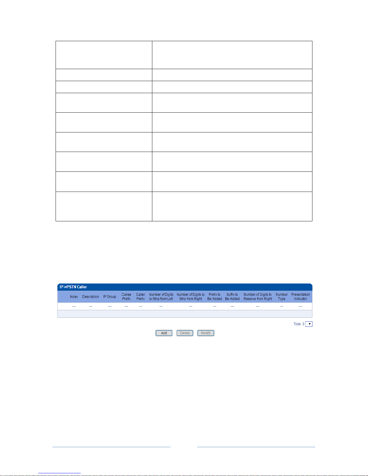
MTG3000 VoIP Trunk Gateway User Manual
69
Copyright @ 2011-2016 Dinstar
‘Any’ means any IP group.
Callee Prefix
Set a prefix for the callee number.
Caller Prefix
Set a prefix for the caller number
Number of Digits to Strip from Left
The number of digits which are lessened from the left of the
caller number
Number of Digits to Strip from Right
The number of digits which are lessened from the right of the
caller number
Prefix to be added
The prefix added to the callee number after its digits are
lessened.
Suffix to be added
The suffix added to the callee number after its digits are
lessened.
Number of Digits to Reserve from
Right
The number of the retained digits which. are counted from the
right of the callee number
Number Type
The type of the callee number. Options include ‘Not Config’,
‘International’, ‘National’, ‘Unknown’, ‘Network Specific’,
‘Subscriber’ and ‘Abbreviated’
4.14.6 IPPSTN Caller
On the IP PSTN Caller interface, you can set rules to change the actual caller number during IP
PSTN calling process.
Click Add, and the following interface will be displayed.
Page 76
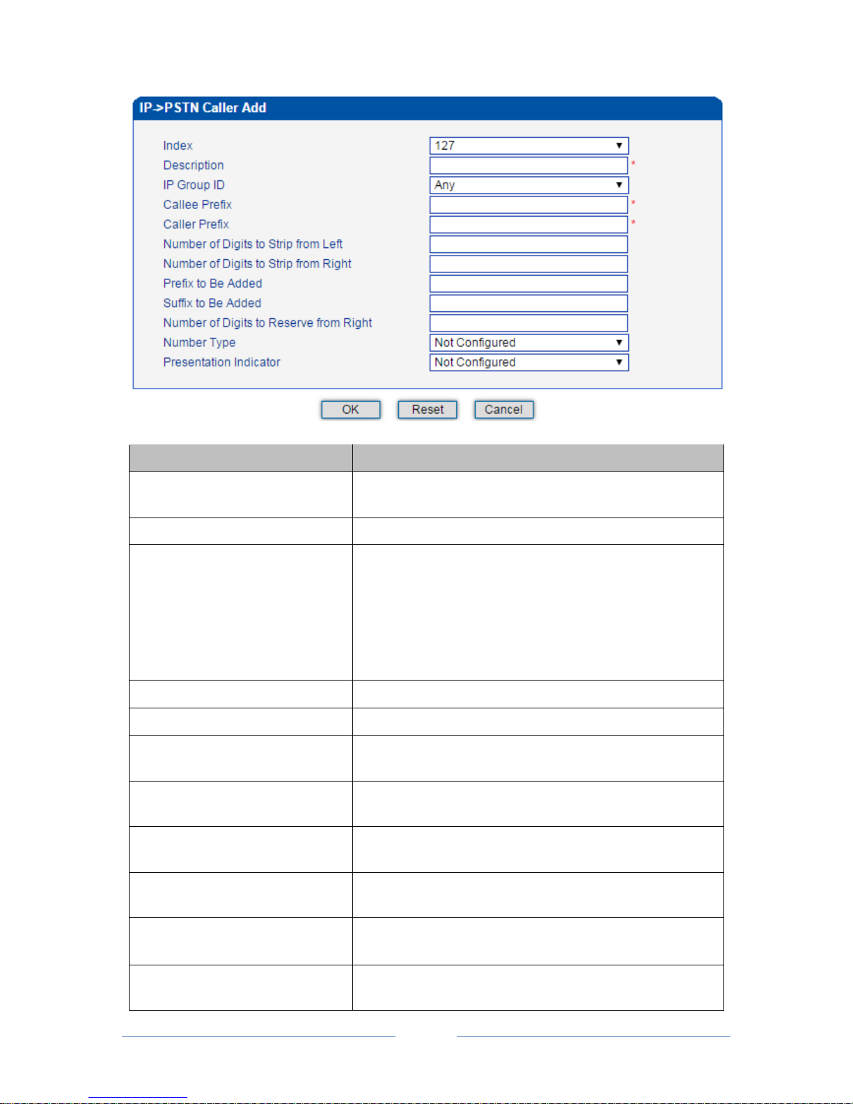
MTG3000 VoIP Trunk Gateway User Manual
70
Copyright @ 2011-2016 Dinstar
Parameter
Explanation
Index
The index of this IP PSTN caller number manipulation, from
0 to 127. Each index cannot be used repeatedly.
Description
The description of this IP PSTN caller number manipulation
IP Group
Select an IP group. The caller number will be manipulated when
a call uses a trunk of this IP group, actual callee prefix matches
the set callee prefix, and actual caller prefix matches the set
caller prefix.
‘Any’ means any IP group.
Callee Prefix
Set a prefix for the callee number.
Caller Prefix
Set a prefix for the caller number
Number of Digits to Strip from Left
The number of digits which are lessened from the left of the
caller number
Number of Digits to Strip from Right
The number of digits which are lessened from the right of the
caller number
Prefix to be added
The prefix added to the caller number after its digits are
lessened.
Suffix to be added
The suffix added to the caller number after its digits are
lessened.
Number of Digits to Reserve from
Right
The number of the retained digits which. are counted from the
right of the caller number
Presentation Indicator
If “Allowed” is selected, the calling number will be presented.
If “Restricted” is selected, the calling number will not be
Page 77
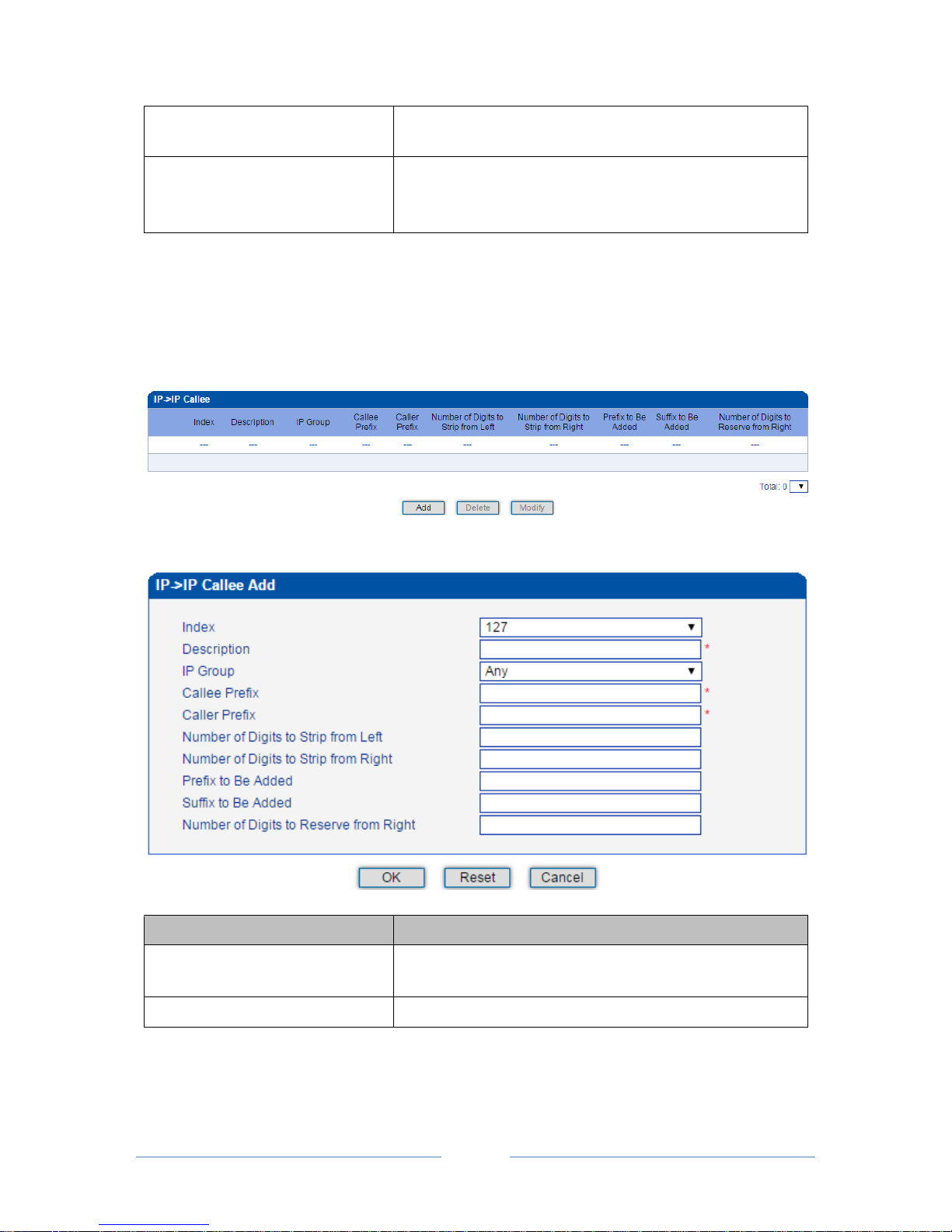
MTG3000 VoIP Trunk Gateway User Manual
71
Copyright @ 2011-2016 Dinstar
presented.
If “Not Config” is selected, the parameter does not work.
Number Type
The type of the caller number. Options include ‘Not Config’,
‘International’, ‘National’, ‘Unknown’, ‘Network Specific’,
‘Subscriber’ and ‘Abbreviated’
4.14.7 IP IP Callee
On the IP IP Callee interface, you can set rules to change the actual callee number during IP IP
calling process.
Click Add, and the following interface will be displayed.
Parameter
Explanation
Index
The index of this IP IP callee number manipulation, from 0 to
127. Each index cannot be used repeatedly.
Description
The description of this IP IP callee number manipulation
Page 78
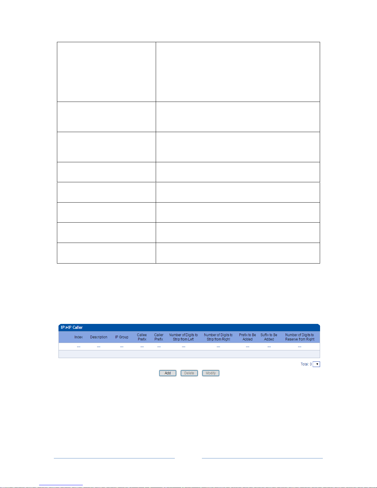
MTG3000 VoIP Trunk Gateway User Manual
72
Copyright @ 2011-2016 Dinstar
IP Group
Select an IP group. The callee number will be manipulated when
a call uses a trunk of this IP group, actual callee prefix matches
the set callee prefix, and actual caller prefix matches the set
caller prefix.
‘Any’ means any IP group.
Callee Prefix
Set a prefix for the callee number. If the actual callee prefix
matches this set callee prefix, the callee number will be
manipulated.
Caller Prefix
Set a prefix for the caller number. If the actual caller prefix
matches the set caller prefix, the callee number will be
manipulated.
Number of Digits to Strip from Left
The number of digits which are lessened from the left of the
callee number
Number of Digits to Strip from Right
The number of digits which are lessened from the right of the
callee number
Prefix to be added
The prefix added to the callee number after its digits are
lessened.
Suffix to be added
The suffix added to the callee number after its digits are
lessened.
Number of Digits to Reserve from
Right
The number of the retained digits which. are counted from the
right of the callee number
4.14.8 IP IP Caller
On the IP IP Caller interface, you can set rules to change the actual caller number during IP IP
calling process.
Click Add, and the following interface will be displayed.
Page 79
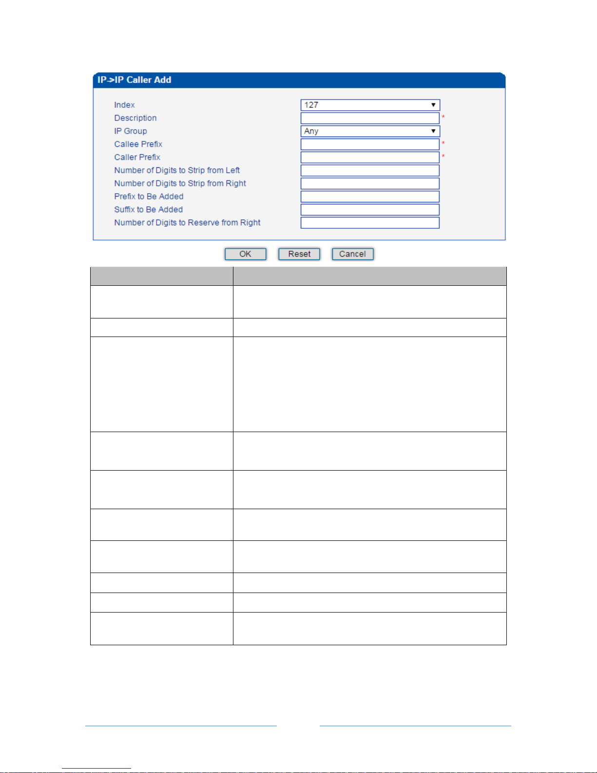
MTG3000 VoIP Trunk Gateway User Manual
73
Copyright @ 2011-2016 Dinstar
Parameter
Explanation
Index
The index of this IP IP caller number manipulation, from 0 to
127. Each index cannot be used repeatedly.
Description
The description of this IP IP caller number manipulation
IP Group
Select an IP group. The caller number will be manipulated when a
call uses a trunk of this IP group, actual callee prefix matches the
set callee prefix, and actual caller prefix matches the set caller
prefix.
‘Any’ means any IP group.
Callee Prefix
Set a prefix for the callee number. If the actual callee prefix
matches this set prefix, the caller number will be manipulated.
Caller Prefix
Set a prefix for the caller number. If the actual caller prefix matches
the set prefix, the caller number will be manipulated.
Number of Digits to Strip from
Left
The number of digits which are lessened from the left of the caller
number
Number of Digits to Strip from
Right
The number of digits which are lessened from the right of the caller
number
Prefix to be added
The prefix added to the caller number after its digits are lessened.
Suffix to be added
The suffix added to the caller number after its digits are lessened.
Number of Digits to Reserve from
Right
The number of the retained digits which. are counted from the right
of the caller number
Page 80
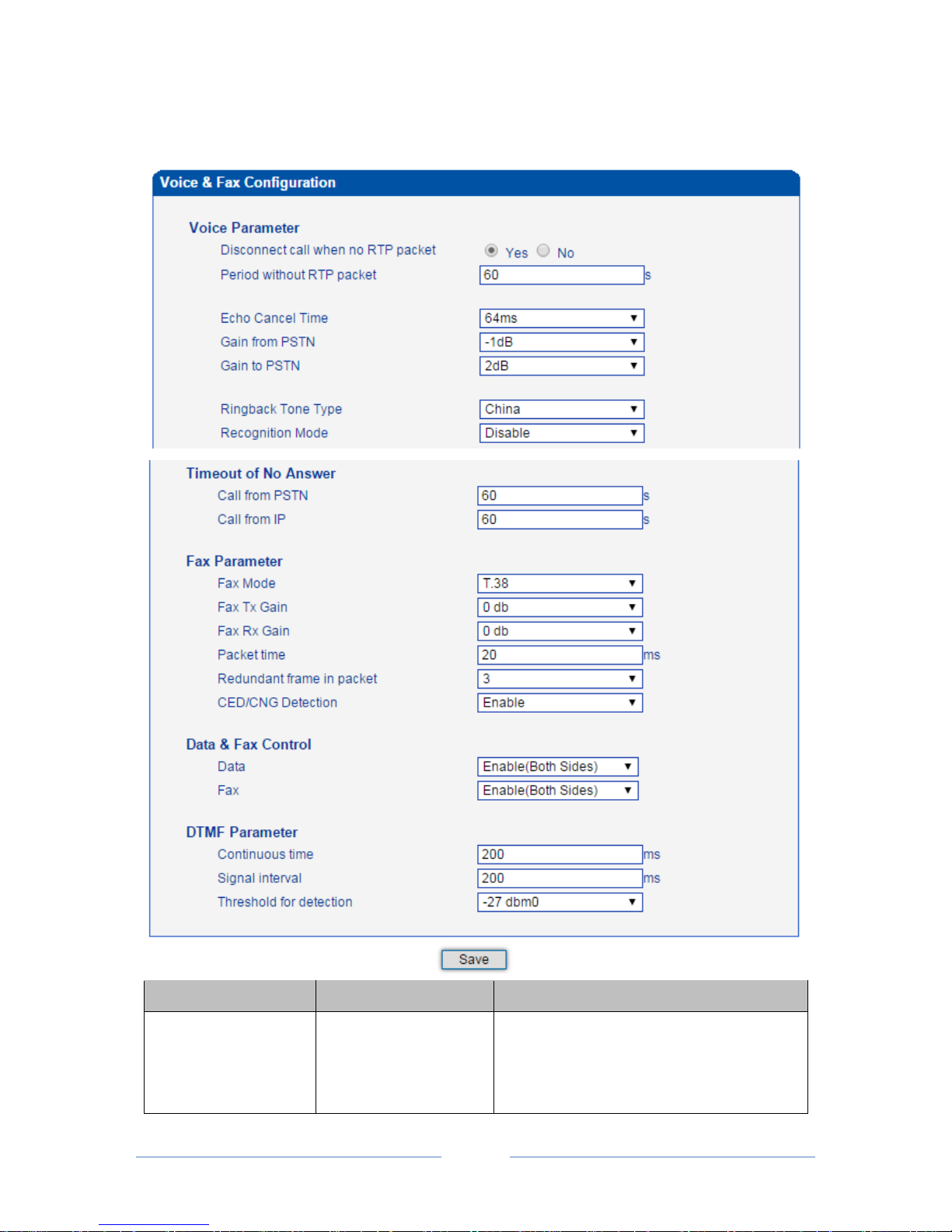
MTG3000 VoIP Trunk Gateway User Manual
74
Copyright @ 2011-2016 Dinstar
4.15 Voice & Fax
Belong to
Parameter
Explanation
Disconnect call when no
RTP packet
Options include ‘Yes’ and ‘No’.
If ‘Yes’ is selected, the call will be disconnected
when it is detected that the call’s silence time is
longer than the set maximum time without
Page 81

MTG3000 VoIP Trunk Gateway User Manual
75
Copyright @ 2011-2016 Dinstar
Voice Parameter
receiving RTP packets.
Period without RTP
packet
The set maximum time without receiving RTP
packets.
Default value is 60 seconds.
Echo Cancel Time
The interval to remove echo from a voice
communication.
Options include 32ms, 64ms and 128ms.
Gain from PSTN
The voice gain from PSTN to IP direction
Default value is -1dB
Gain to PSTN
The voice gain from IP to PSTN direction
Default value is 2dB
Ringback Tone Type
Local ringback tone
Recognition Mode
Whether to recognize voice when prompt tone
is played.
Timeout of No Answer
Call from PSTN
The maximum time of no answer for calls from
PSTN
Call from IP
The maximum time of no answer for calls from
IP Network
Fax Parameter
Fax Mode
Options include T.38, Pass-through and
Adaptive.
Default value is T.38.
Adaptive means auto negotiate with peer side.
Fax Tx Gain
Gain of sending a fax
Fax Rx Gain
Gain of receiving a fax
Packet time
The time for data packing
Redundant frame in
Packet
The length of frame in RTP packet
CED/CNG Detection
Whether to detect CED/CNG
Data & Fax Control
Data
Whether to enable voice data service on the
MTG3000
Fax
Whether to enable fax service on the MTG3000
DTMF Parameter
Continuous time
The duration of a DTMF signal
Signal Interval
The interval between two DTMF signals
Threshold for Detection
The signal detection threshold
Page 82
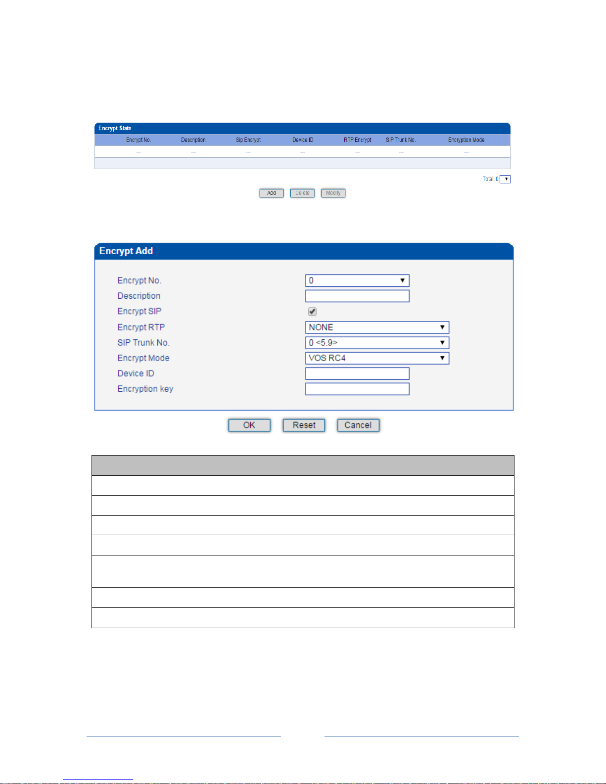
MTG3000 VoIP Trunk Gateway User Manual
76
Copyright @ 2011-2016 Dinstar
4.16 Encrypt Config
On the Encrypt Config interface, you can set parameters related to encryption.
Click Add, and the following interface will be displayed.
Parameter
Explanation
Encrypt No.
The No. of this encryption
Description
The description of this encryption
Encrypt SIP
Whether to encrypt SIP message
Encrypt RTP
Whether to encrypt RTP packet
SIP Trunk No.
The No. of the SIP trunk that transmits the SIP message to be
encrypted.
Encrypt Mode
Only support VOS RC4 at present
Device ID
The ID of the SIP account to which the SIP trunk belongs
Page 83
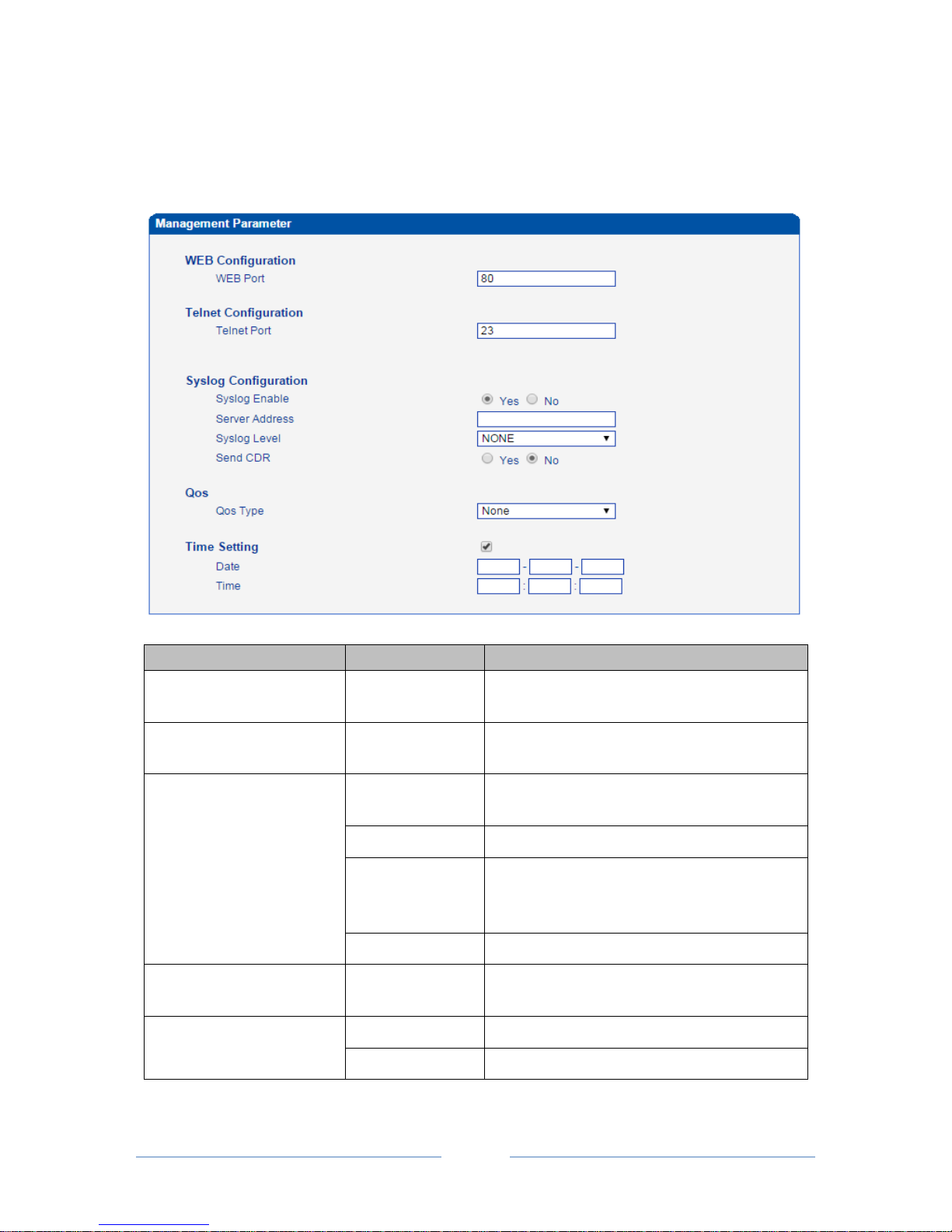
MTG3000 VoIP Trunk Gateway User Manual
77
Copyright @ 2011-2016 Dinstar
4.17 Maintenance
4.17.1 Management Parameter
Belong To
Parameter
Explanation
WEB Configuration
WEB Port
Listening port of local WEB service
Default is 80.
Telnet Configuration
Telnet Port
Listening port of local Telnet service
Default is 23.
Syslog Configuration
Syslog Enable
Whether to enable Syslog
Default is No.
Server Address
Address to save system logs
Syslog Level
The system log type.
Options include ‘Debug’, ‘Info’, ‘Notice’,
‘Warning’, ‘Error’ and ‘None’.
Send CDR
Whether to send CDR (Call detail Record).
Qos
Qos Type
Options include ‘None’, ‘TOS’ and ‘DS’.
TOS only supports IPv4.
Time Setting
Date
The date displayed on the WEB interface
Time
The time displayed on the WEB interface
Page 84
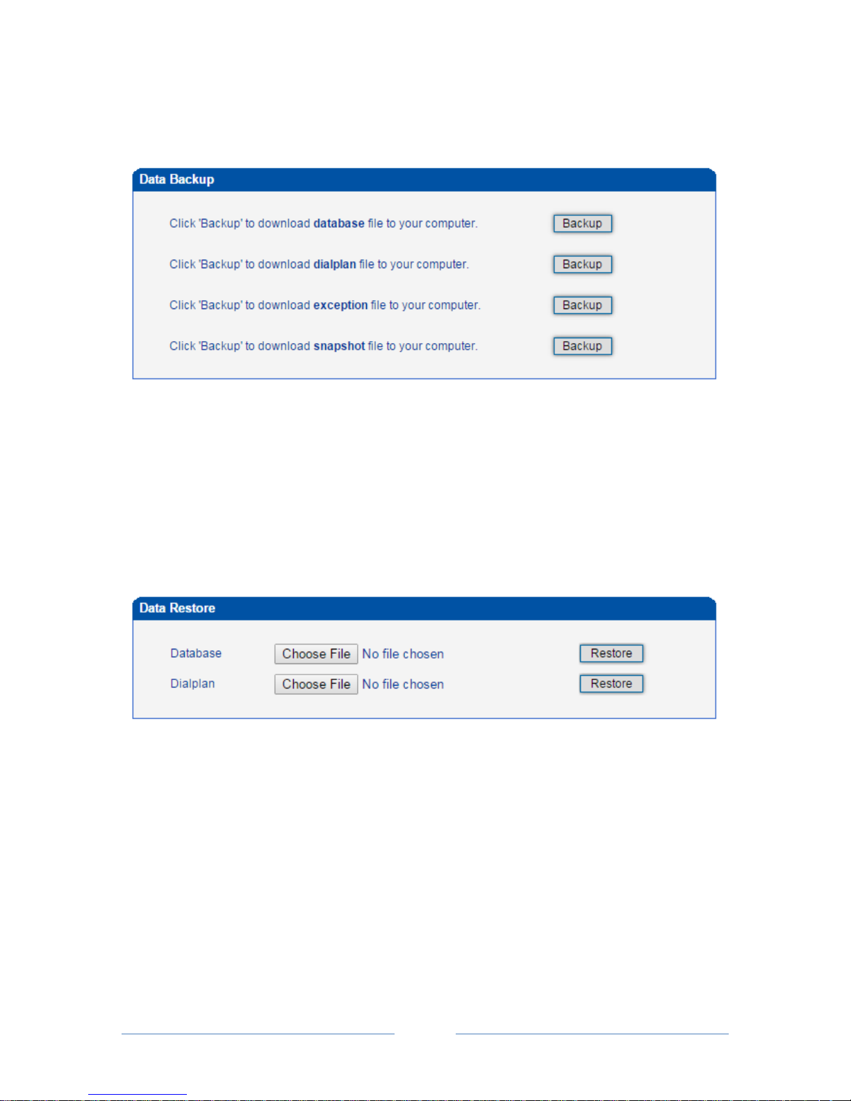
MTG3000 VoIP Trunk Gateway User Manual
78
Copyright @ 2011-2016 Dinstar
4.17.2 Data Backup
On the Data Backup interface, you can click Backup to download database file, dialplan file, exception
file and snapshot file.
4.17.3 Data Restore
On the Data Restore interface, you can restore database and dialplan. If you upload a file that contains
default configurations, the MTG3000 will be restored to default configurations. You can also upload a
dialplan file to restore dialing rules.
Database herein refers to the database where configuration data are placed.
4.17.4 Network Capture
On the following interface, you can capture data packages of the GE0 port or GE1 port of a selected DTU
board. You can also set a specific protocol to capture the packages that you want.
Page 85
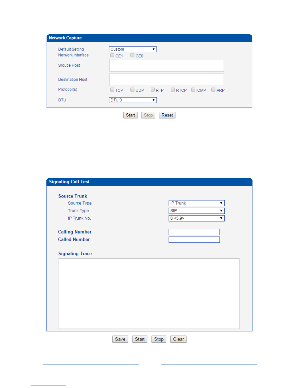
MTG3000 VoIP Trunk Gateway User Manual
79
Copyright @ 2011-2016 Dinstar
4.17.5 Signaling Call Test
On the Signaling Call Test interface, you can test whether the signaling of a call is successfully connected.
You need to select the source type, trunk type and IP trunk No. of the call, and enter the calling number and
called number. If the signaling of a call fails, you can find out where errors have occurred through the
messages returned in the Signaling Trace box.
Page 86
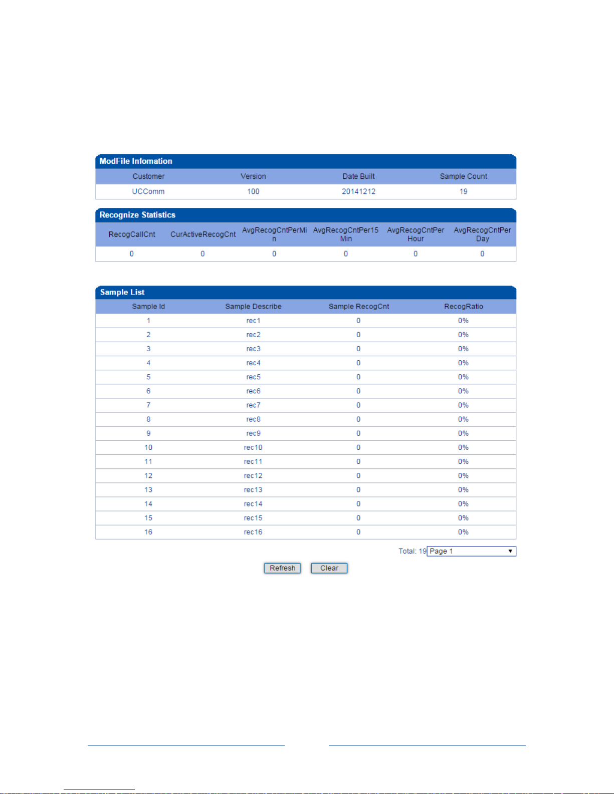
MTG3000 VoIP Trunk Gateway User Manual
80
Copyright @ 2011-2016 Dinstar
4.17.6 ModFile Information
ModFile is voice recognition file which provides the number of total calls recognized, the number of calls
currently recognized, the number of the calls recognized in the past one minutes, the number of the calls
recognized in the past 15 minutes, the number of the calls recognized in the past one hour and the number
of the calls per day.
4.17.7 Version Information
On the Version Information interface, the version information of the software, database, Web, FPGA, DSP
and DTU boards are displayed.
Page 87
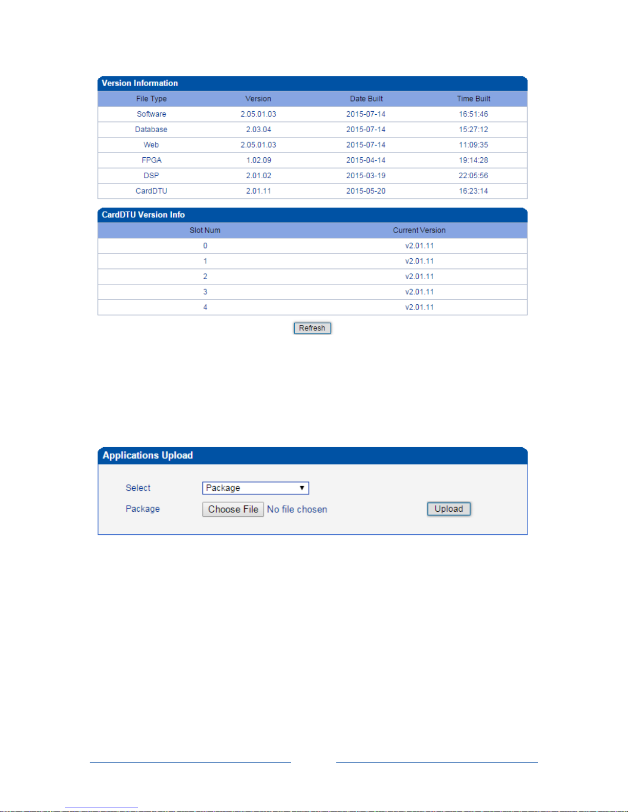
MTG3000 VoIP Trunk Gateway User Manual
81
Copyright @ 2011-2016 Dinstar
4.17.8 Firmware Upgrade
On the Applications Upload interface, you can upload files to upgrade the software, the Web, and the
Modfile of MTG3000. If you select ‘Package’, it means the upgrading files of the software and Web are
packaged and then uploaded.
4.17.9 Password Modification
On the Password Modification interface, you can modify password for logging in the MTG3000 device.
Default password is admin, so it is advised to modify it for security consideration.
The abovementioned password is also used to log in Web Interface, Telnet and SSH.
Page 88
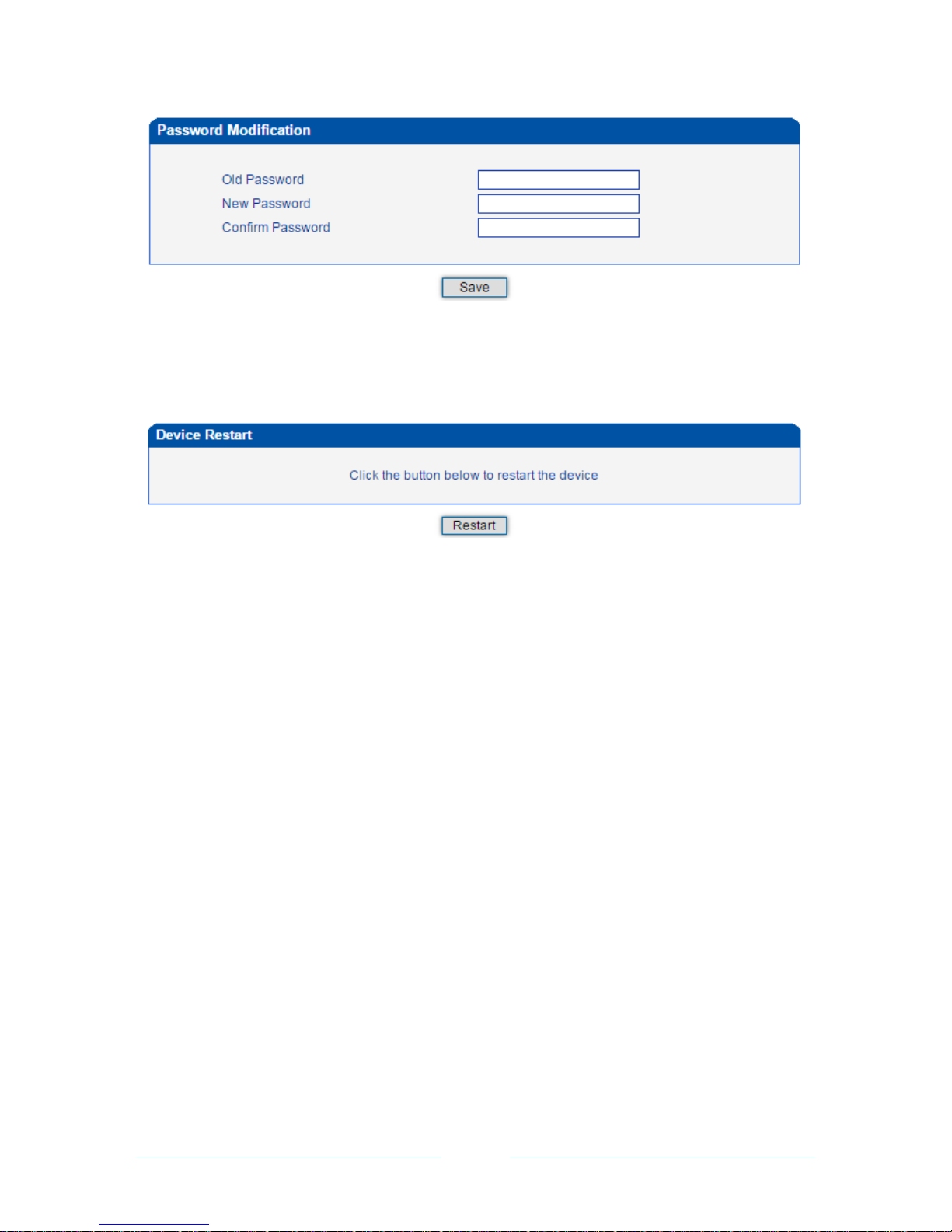
MTG3000 VoIP Trunk Gateway User Manual
82
Copyright @ 2011-2016 Dinstar
4.17.10 Device Restart
Click the Restart button, and you can restart the MTG3000 device.
Page 89

MTG3000 VoIP Trunk Gateway User Manual
83
Copyright @ 2011-2016 Dinstar
5 Abbreviation
Abbreviation
Full Name
PRI
Primary Rate Interface
DND
Do-not-Disturb
FMC
Fixed Mobile Convergence
SIP
Session Initiation Protocol
DTMF
Dual Tone Multi Frequency
USSD
Unstructured Supplementary Service Data
PSTN
Public Switched Telephone Network
STUN
Simple Traversal of UDP over NAT
IVR
Interactive Voice Response
ISUP
ISDN (Integrated Services Digital Network) User Part
NTP
Network Time Protocol
PBX
Private Branch Exchange
RTP
Real Time Protocol
RTCP
Real Time Control Protocol
SNMP
Simple Network Management Protocol
SS7
Signaling System Number 7
TUP
Telephone User Part
LOS
Loss of Signal
RAI
Remote Alarm Indicator
AIS
Alarm Indication Signal
LFA
Loss of Frame Alignment
ISDN
Integrated Services Digital Network
CIC
Circuit Identification Code
SPC
Signaling point code
PCM
Pulse Code Modulation
CLI
Calling Line Identification
Page 90
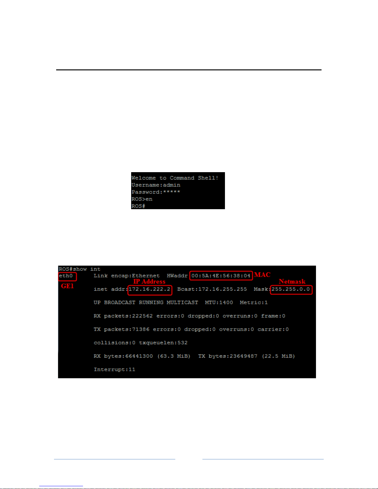
MTG3000 VoIP Trunk Gateway User Manual
84
Copyright @ 2011-2016 Dinstar
6 Commands
6.1 Commands under en Mode
This section is aimed to guide customers to get more details of MTG3000 gateway through command lines.
It introduces the command lines that are commonly used.
6.1.1 Login Command
Run the PuTTY software, and login MTG3000 gateway through Telnet. Enter username and password,
and then run command en to activate the privileged commands.
6.1.2 Query IP Address
Enter the command show int, IP address, MAC address and Netmask of GE1 are displayed.
6.1.3 Query Statistics about DTU
Enter the command show card, and statistics about DTU are displayed.
Page 91
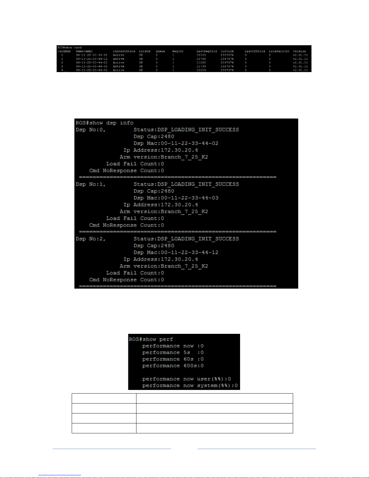
MTG3000 VoIP Trunk Gateway User Manual
85
Copyright @ 2011-2016 Dinstar
6.1.4 Query DSP Information
Enter the command show dsp info, and DSP information is displayed.
6.1.5 Query CPU Performance
Enter the command show perf, the CPU performance is displayed.
Performance now
CPU load at current time
Performance 5s
Average CPU load in recent 5 seconds
Performance 60s
Average CPU load in recent 60 seconds
Performance 600s
Average CPU load in recent 600 seconds
Page 92
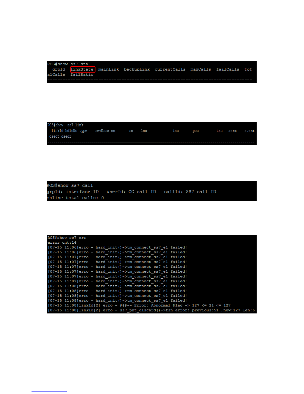
MTG3000 VoIP Trunk Gateway User Manual
86
Copyright @ 2011-2016 Dinstar
6.1.6 Query SS7 Trunk Status
Enter the command show ss7 sta, and the status of SS7 link is displayed.
6.1.7 Query SS7 Link Statistics
Enter the command show ss7 link, and statistics about SS7 link are displayed.
6.1.8 Query SS7 Call Statistics
Enter the command show ss7 call, and statistics about SS7 calls are displayed.
6.1.9 Query SS7 Errors
Enter the command show ss7 err, and errors about SS7 trunks or SS7 links are displayed.
6.1.10 Query PRI Trunk Status
Enter the command show q931 sta, and statuses of PRI trunks are displayed.
Page 93

MTG3000 VoIP Trunk Gateway User Manual
87
Copyright @ 2011-2016 Dinstar
6.1.11 Query PRI Link Statistics
Enter the command show q931 link, and PRI link statistics are displayed.
6.1.12 Query PRI Call Statistics
Enter the command show q931 call, and statistics about PRI calls are displayed.
6.1.13 Query Packet Statistics of HDLC Channel and Related Error Codes
Enter the command show mcc x (x refers to the port No. of HDLC channel), and the packet statistics and
error codes (if there are any) of the HDLC channel are displayed.
6.1.14 Query Status of E1 Port
Enter the command show e1 x (x refers to the E1 port No.), and the status of the E1 port is displayed.
6.1.15 Query Statistics of All Calls
Enter the command show cc calls, and the statistics of all calls are displayed.
6.2 Commands under config Mode
6.2.1 Login Commands
Welcome to Command Shell!
Username:admin
Password:*****
ROS>en
ROS#
ROS#^config
ROS(config)#
6.2.2 Other Commands
Used For/To
Command
Query version information
ROS(config)# load show
Call tracing
ROS(config)#deb cc detail all
ROS(ada)#turnon 27
Page 94

MTG3000 VoIP Trunk Gateway User Manual
88
Copyright @ 2011-2016 Dinstar
SIP signal tracing
ROS(config)#deb sip msg all
ROS(ada)#turnon 71
Query SS7 Signal
ROS(config)#deb ss7 <lnkId> <level>
ROS(ada)#turnon 96
Query PRI Signal
ROS(config)#deb q931 detail
ROS(ada)#turnon 64
Restart MTG3000
ROS(config)#reset gmpu [ipaddr]
6.3 Commands under ada Mode
6.3.1 Login Commands
Welcome to Command Shell!
Username:admin
Password:*****
ROS>en
ROS#
ROS#^ada
ROS(ada)#[119-17:35:18:040]ADA CONNECTED ...,WELCOME!
ROS(ada)#
Used For/To
Command
Query the records about exceptions or errors
ROS(ada)#cmd 3 30 0
Query the records about exceptions or errors before
the restart of MTG3000
ROS(ada)#cmd 3 30 1
Disable the printing of SIP messages
ROS(ada)#turnoff 71
Disable the printing of SS7 messages
ROS(ada)#turnoff 96
Disable the printing of PRI messages
ROS(ada)#turnoff 64
Disable the printing of CC messages
ROS(ada)#turnoff 27
 Loading...