

Page 1

DWG2000E/F/G GSM/CDMA VoIP Gateway
User Manual
Shenzhen Dinstar Technologies Co., Ltd.
Address: Floor 6, Guoxing Building, Changxing Road, Nanshan District, Shenzhen,
China
Postal Code: 518052
Telephone: +86 755 2645 6664
Fax: +86 755 2645 6659
Emails: [email protected], [email protected]
Website: www.dinstar.com www.dinstar.cn
Page 2
DWG2000E/F/G GSM/CDMA VoIP Gateway User Manual
Document
Version
Firmware
Version
Author
Date
Description
V1.0
02.22/23.08.01
Technical Support
2013-07
First release
Revision Records
_______________________________________________________________________________
Shenzhen Dinstar Technologies Co., Ltd.
1
Page 3

DWG2000E/F/G GSM/CDMA VoIP Gateway User Manual
Table of Contents
1. Product Description ................................................................................................................... 5
1.1 Overview ........................................................................................................................... 5
1.2 Scenario of Application ................................................................................................... 5
1.3 Product Appearance ........................................................................................................ 5
1.4 Functions and Features .................................................................................................. 7
1.4.1 Protocols ................................................................................................................ 7
1.4.2 System Function ................................................................................................... 7
1.4.3 Industrial Standards Supported .......................................................................... 8
1.4.4 General Hardware Specification ......................................................................... 8
2. Installation Guide ....................................................................................................................... 9
2.1 Installation Notice............................................................................................................. 9
2.2 Installation Procedure ..................................................................................................... 9
2.2.1 Install SIM Card .................................................................................................... 9
2.2.2 Antenna Installation .............................................................................................. 9
2.2.3 Network Cable Connection of Equipment ....................................................... 10
3. Basic Operation ........................................................................................................................ 11
3.1 IVR Navigator ................................................................................................................. 11
3.2 Basic Operation.............................................................................................................. 11
4. WEB Interface Configuration .................................................................................................. 12
4.1 Access DWG2000E unit ............................................................................................... 12
4.2 Parameters Configuration............................................................................................. 13
4.3 System Information ........................................................................................................ 14
4.3.1 System Information ............................................................................................ 14
4.3.2 Mobile Information .............................................................................................. 15
4.3.3 SIP Information ................................................................................................... 16
4.4 Statistics .......................................................................................................................... 17
4.4.1 TCP/UDP ............................................................................................................. 17
4.4.2 RTP ....................................................................................................................... 17
4.4.3 SIP Call History ................................................................................................... 17
4.4.4 IP to GSM Call History ....................................................................................... 18
4.4.5 CDR Report ......................................................................................................... 19
4.4.6 Auto Lock BCCH History ................................................................................... 20
4.5 Network Configuration .................................................................................................. 20
4.5.1 Local Network ..................................................................................................... 20
4.5.2 ARP ....................................................................................................................... 21
4.5.3 VPN Parameter ................................................................................................... 22
4.6 Mobile Configuration ..................................................................................................... 23
4.6.1 Basic Configuration ............................................................................................ 23
Example: ........................................................................................................................ 24
Configuration between SMS box and gateway ................................................ 24
_______________________________________________________________________________
Shenzhen Dinstar Technologies Co., Ltd.
2
Page 4

DWG2000E/F/G GSM/CDMA VoIP Gateway User Manual
Configure API parameters on gateway ............................................................. 24
Configure SMS box .............................................................................................. 24
how to configure abnormal call on gateway ..................................................... 25
Low ASR Less Than 20%.................................................................................... 26
Low ACD Less Than 300s ................................................................................... 26
Counts of Call Failed ............................................................................................ 26
Mobile Operate ..................................................................................................... 26
4.6.2 Mobile Configuration ........................................................................................... 26
How to configure maximum call limitation ......................................................... 28
4.6.3 PIN Management ................................................................................................ 29
4.6.5 SMSC ................................................................................................................... 30
4.6.6 Send SMS/Recv SMS ........................................................................................ 30
4.6.7 USSD.................................................................................................................... 31
4.6.8 Carrier .................................................................................................................. 31
4.6.9 BCCH ................................................................................................................... 32
4.6.10 Call Forwarding................................................................................................. 33
4.6.11 Call Waiting ........................................................................................................ 33
4.6.12 SIM Mode .......................................................................................................... 34
4.6.13 Cloud Server ..................................................................................................... 35
4.7 Routing Configuration ................................................................................................... 36
4.7.1 Routing Parameter ............................................................................................. 36
4.7.2 IP->Tel Routing ................................................................................................... 37
4.7.3 Tel->IP Routing ................................................................................................... 38
4.8 Manipulaton Configuration ........................................................................................... 40
4.8.1 IP->Tel Destination Numbers ............................................................................ 40
4.8.2 Tel->IP Source Numbers ................................................................................... 42
4.8.3 Tel->IP Destination Numbers ............................................................................ 44
4.9 Operation ........................................................................................................................ 46
4.9.1 IP->Tel Operation................................................................................................ 46
4.9.2 Tel->IP Operation ................................................................................................ 48
4.10 Port Group Configuration ........................................................................................... 50
4.10.1 Port Group ......................................................................................................... 50
4.11 IP Trunk Configuration ................................................................................................ 50
4.11.1 IP Trunk .............................................................................................................. 50
4.11.2 IP Trunk Group .................................................................................................. 51
4.12 System Configuration .................................................................................................. 52
4.12.1 Service Parameter ........................................................................................... 52
4.12.2 SIP Parameter .................................................................................................. 56
4.12.3 Port Parameter ................................................................................................. 62
4.13 Digit Map ....................................................................................................................... 64
4.14 Tools .............................................................................................................................. 65
4.14.1 Firmware Upload .............................................................................................. 65
4.14.2 Syslog ................................................................................................................ 66
_______________________________________________________________________________
Shenzhen Dinstar Technologies Co., Ltd.
3
Page 5

DWG2000E/F/G GSM/CDMA VoIP Gateway User Manual
4.14.3 Filelog /Filelog Download ................................................................................ 67
4.14.4 Management Parameter ................................................................................. 67
4.14.5 Config Backup .................................................................................................. 68
4.14.6 Config Restore .................................................................................................. 68
4.14.7 IVR Voice Prompt Upload ............................................................................... 69
4.14.8 Ping Test ............................................................................................................ 69
4.14.9 Tracert Test ........................................................................................................ 70
4.14.10 Network Capture ............................................................................................ 70
4.14.11 Voice Loopback Test ...................................................................................... 74
4.14.13 Username & Password ................................................................................. 75
4.14.14 Factory Reset ................................................................................................. 76
4.14.15 Restart ............................................................................................................. 76
5. Troubleshooting and Command Line .................................................................................... 77
5.1 Login DWG & General Knowledge of DWG Command ........................................... 77
5.2. Commands in "ROS#" Mode ...................................................................................... 77
5.2.1 Summarize of commands in "ROS#" mode ........................................................... 77
5.2.2 General Purpose Commands in "ROS#" mode ..................................................... 78
Show IP address (show int) ........................................................................................ 78
Show Time (show clock) .............................................................................................. 78
Show version (show version) ...................................................................................... 78
Show sip Information (show sip config) .................................................................... 79
Show memory status (show memory detail) ............................................................ 80
Show SIP port status (show sip all) ........................................................................... 80
Show Current calls (sh ecc call) ................................................................................. 80
Show RTP session ( sho rtp se) ................................................................................. 81
Show ASR/ACD statistics (show ecc state) .............................................................. 81
5.3 Commands in "Config" Mode .................................................................................... 81
5.3.1 Summarize of commands in "config" mode ............................................................ 81
5.3.2 General Purpose Commands in "Config" mode .................................................... 82
Set time (clock set) ....................................................................................................... 82
Save the configuration (save) ..................................................................................... 83
Restart device (reset eia) ............................................................................................ 83
Enable debug ................................................................................................................ 83
Enable SIP debug (deb sip msg all) .......................................................................... 83
5.4 How to trace SIP logs .................................................................................................... 83
5.5 How to trace ECC logs (Call Details) .......................................................................... 84
5.6 How to trace Module logs ............................................................................................. 84
6. The Way to Increase Antenna Isolation ................................................................................ 86
7. Frequency Asked Questions .................................................................................................. 89
8. Glossary .................................................................................................................................... 91
_______________________________________________________________________________
Shenzhen Dinstar Technologies Co., Ltd.
4
Page 6
DWG2000E/F/G GSM/CDMA VoIP Gateway User Manual
1. Product Description
This chapter mainly introduces functions and structures of DWG2000E/F/G.
1.1 Overview
DWG2000E/F/G serials GSM/CDMA VoIP Gateway is full functions VoIP gateway based on IP
and Mobile network, which provides a flexible network configuration, powerful features, and
good voice quality. It works for carrier grade, enterprise, SOHO, residential users for
cost-effective solution.
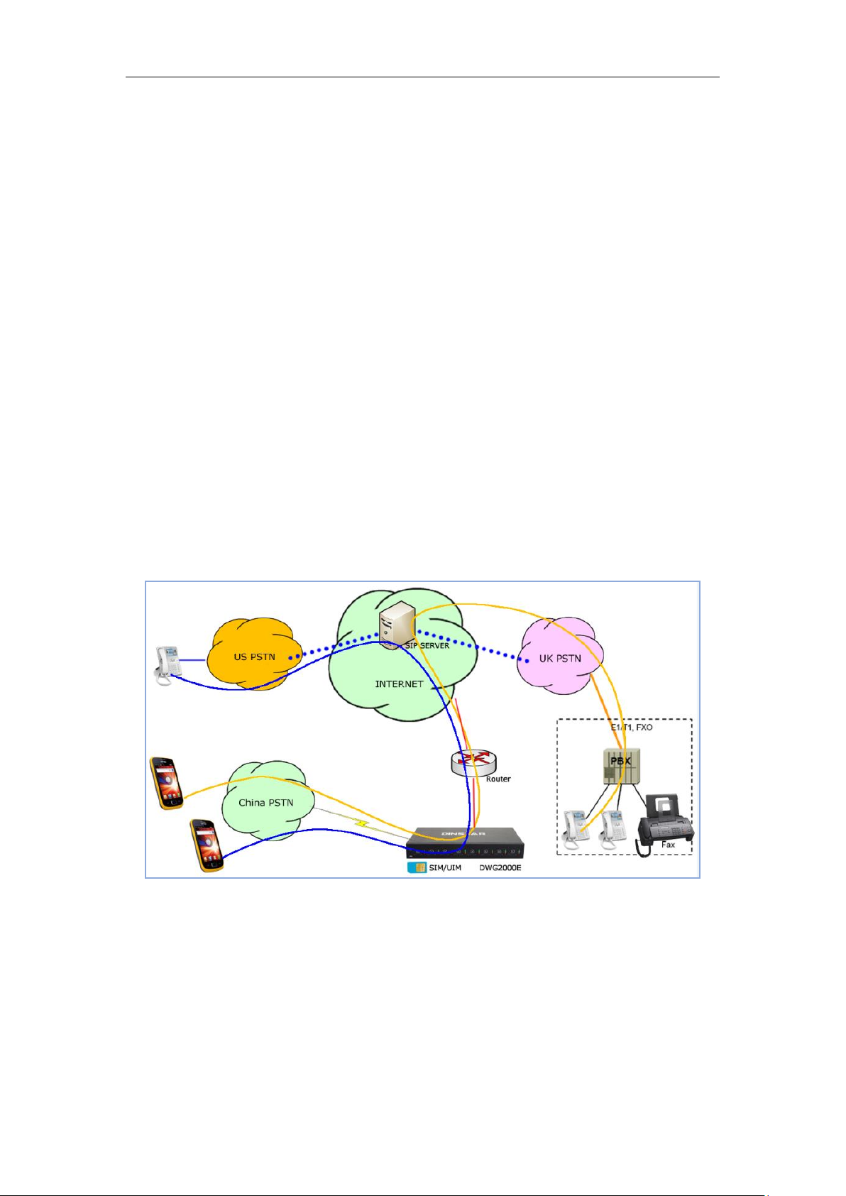
1.2 Scenario of Application
With the development of users and telecom service, mobile network and fixed network
integration will be steadily increasing. DWG2000E/F/G provides high quality VoIP service
which perfectly meets the requirement. This is a scenario shown as figure 1-2-1
Figure 1-2-1 Network scenario
1.3 Product Appearance
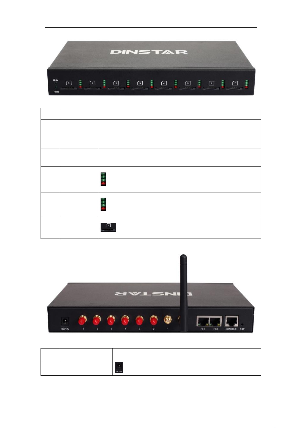
The appearance of DWG2000E shows as follow
Figure 1-3-1 Front view of DWG2000E-8G/8C
_______________________________________________________________________________
Shenzhen Dinstar Technologies Co., Ltd.
5
Page 7
DWG2000E/F/G GSM/CDMA VoIP Gateway User Manual
Index
Indicators
Description
1
RUN
On: Starting
Off: Abnormal
Blinking every 0.5s: Normal status
2
PWR
On: Power on
Off: Power off
3
Signal
Signal strength indicators with green color
4
Channel
Use/Unuse indicator with Red color, ON is used, Off is unused
5
SIM Slots
SIM card slot
Index
Interface
Description
1
Power Connector
Power connector of DC power. Input: DC12V
Table 1-3-1 Description of Front view
Figure 1-3-2 Rear view of DWG2000E-8G/8C
Table 1-3-2 Description of Rear view
_______________________________________________________________________________
Shenzhen Dinstar Technologies Co., Ltd.
6
Page 8
DWG2000E/F/G GSM/CDMA VoIP Gateway User Manual
2
Antenna Connector
Mark as digits 0 to 7
3
Network
FE0 and FE1, its default IP address 192.168.11.1
4
Console
RS232 standard, band rate 115200bps
5
RST
Reset button to restore default IP and password or restore
factory setting.
Restore IP and Password: hold RST button 3~5 seconds,
RUN LED being ON during this time
Restore factory setting: Hold RST button 7 seconds,
RUN LED being blink
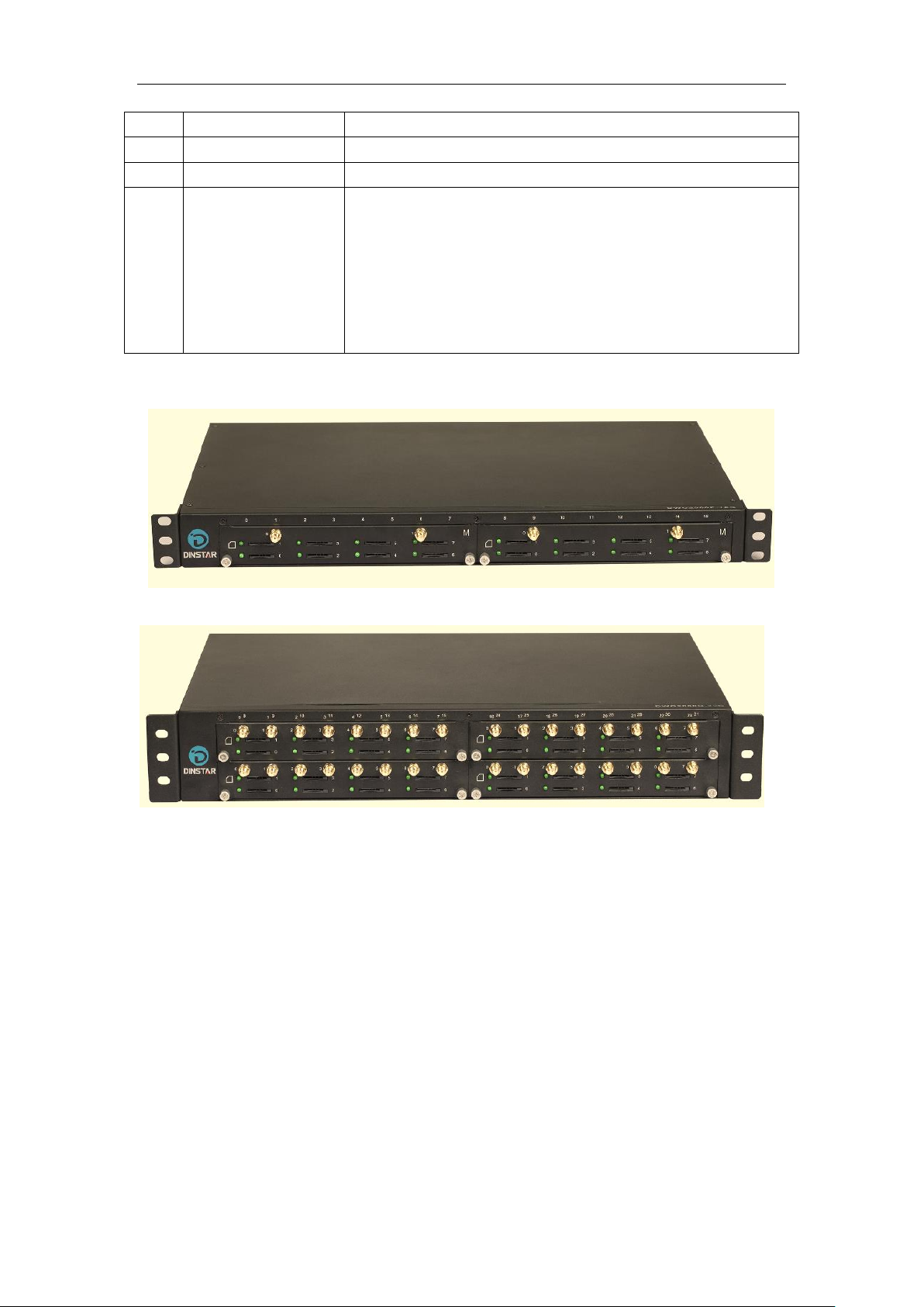
The appearance of DWG2000F
The appearance of DWG2000G
1.4 Functions and Features
1.4.1 Protocols
Standard SIP;
Simple Traversal of UDP over NATs (STUN);
Point-to-point protocol over Ethernet (PPPoE);
Hypertext Transfer Protocol (HTTP);
Dynamic Host Configuration Protocol (DHCP);
Domain Name System (DNS);
ITU-T G.711α-Law/μ-Law、G.723.1、G.729AB;
PPTP available on DWG2000E
1.4.2 System Function
PLC: Packet loss concealment
_______________________________________________________________________________
Shenzhen Dinstar Technologies Co., Ltd.
7
Page 9

DWG2000E/F/G GSM/CDMA VoIP Gateway User Manual
VAD: Voice activity detection
CNG: Comfort Noise Generation
Local/Remote SIM card work mode
Adjustable gain of port
DTMF adjustment
Balance Check
Lock/unlock SIM/UIM
Mobile number display rejection
Sending/receiving SMS
Customize IVR Recording
White and black list
One number access
Open API for SMS, support USSD
Echo Cancellation (with ITU-T G.168/165 standard)
Automatic negotiate network
Hotline
BCCH
1.4.3 Industrial Standards Supported
Stationary use environment: EN 300 019: Class 3.1
Storage environment: EN 300 019: Class 1.2
Transportation environment: EN 300 019: Class 2.3
Acoustic noise: EN 300 753
CE EMC directive 2004/108/EC
EN55022: 2006+A1:2007
EN61000-3-2: 2006,
EN61000-3-3: 1995+A1: 2001+A2: 2005
EN55024: 1998+A1: 2001+A2: 2003
Certifications: FCC, CE
1.4.4 General Hardware Specification
Power Supply
Input: 100-240V, 50-60Hz
Temperature(Operation): 0 ℃ ~ 45 ℃
(Storage): -20 ℃ ~80 ℃
Operation Humidity: 10%-90% No Condensation
_______________________________________________________________________________
Shenzhen Dinstar Technologies Co., Ltd.
8
Page 10
DWG2000E/F/G GSM/CDMA VoIP Gateway User Manual
2. Installation Guide
This chapter mainly introduces DWG2000E hardware installation as example and connection
of device.
Tips:The installation steps are suitable for DWG2000F/G serials gateway also.
2.1 Installation Notice
DWG2000E-4/8 G/C adapts 12VDC. Power adapter, make sure AC power supply grounded
well to ensure the reliability and stability;
Notes: incorrect power connection may damage power adapter and device.
DWG2000E-4/8 G/C provides standard RJ45 with 10Mbps or 100Mbps interfaces.
For Wireless part, make sure antennas connecting well on device. Inserting SIM cards and
GSM channels should work properly.
2.2 Installation Procedure
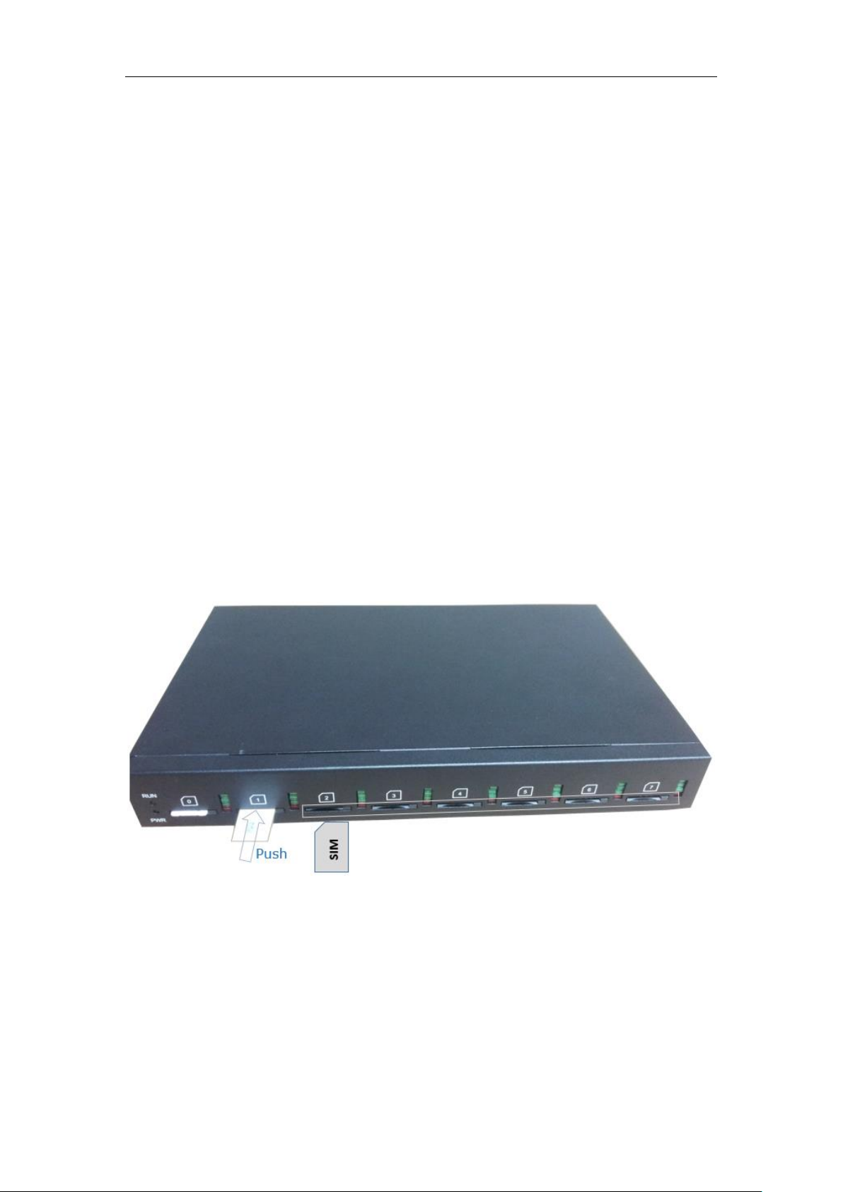
2.2.1 Install SIM Card
Figure 2-2-1 SIM Card installation
2.2.2 Antenna Installation
Figure 2-2-4 Antenna Installation
_______________________________________________________________________________
Shenzhen Dinstar Technologies Co., Ltd.
9
Page 11
DWG2000E/F/G GSM/CDMA VoIP Gateway User Manual
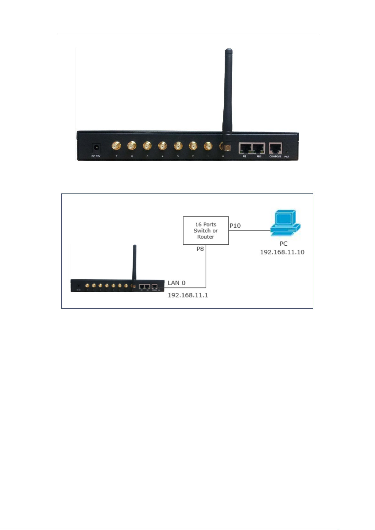
2.2.3 Network Cable Connection of Equipment
Figure 2-2-5 DWG2000E network connection
_______________________________________________________________________________
Shenzhen Dinstar Technologies Co., Ltd.
10
Page 12
DWG2000E/F/G GSM/CDMA VoIP Gateway User Manual
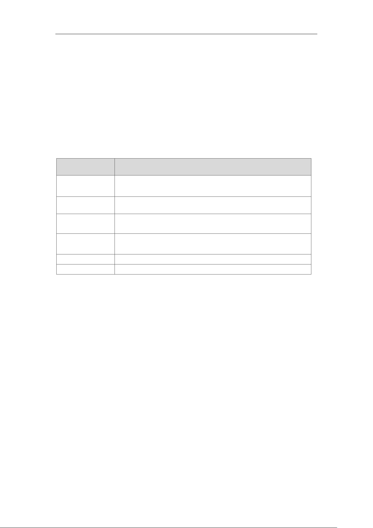
Dial numbers
Features
*150*a#
Set IP address(static/DHCP), a can be digit 1 or 2,*150*1# is static
IP address mode, *150*2# is DHCP mode
*152*a*b*c*d#
Configure IP address, a, b, c, d are the four fields of IP address.
*153*a*b*c*d#
Configure subnet mask. a, b, c, d are the four fields of the subnet
mask
*156*a*b*c*d#
Configure the device gateway, a, b, c, d are the four fields of the
device gateway
*158#
Query the IP address
*111#
Restart device
3. Basic Operation
In this chapter is mainly to introduce basic operation of gateway.
3.1 IVR Navigator
The gateway is embeded IVR system for local maintainance.In each step, if user hears an IVR
message of “setting succeed”, which means that user has finished this step successfully.
However, if user hears a “setting failed” message, please check and redo that step again.
Table 3-1 Feature codes for system setting
3.2 Basic Operation
3.2.1 Check IP address
With a Mobile phone call the SIM card number, the gateway will answer and play voice prompt
‘dial the extension number’, press *158# on mobile phone then local IP address will be
reported by gateway automatically.
3.2.2 Restore factory setting via IVR
With a Mobile phone call the SIM card number, the gateway will answer and play voice prompt
‘dial the extension number’, press *166*000000# on mobile phone then the user will hear
‘setting succeed’. Reboot gateway to take setting effective.
3.2.3 Restore default IP and password
Press RST button about 3 seconds then reboot gateway. The IP address, username and
password will be back to factory default.
3.2.4 Restore factory setting
Press RST button about 7 seconds then reboot gateway then it will restore to factory setting.
_______________________________________________________________________________
Shenzhen Dinstar Technologies Co., Ltd.
11
Page 13
DWG2000E/F/G GSM/CDMA VoIP Gateway User Manual
3.2.5 Console port access
The gateway provide Console port for maintenance purpose. It adopts RS232 standards with
band rate 115200bps.
4. WEB Interface Configuration
DWG2000F/G serials gateway has the same web interface. This charpter describes web
configuration of DWG2000E. The DWG2000E contains an embedded web server to set
parameters by using the HTTP protocol. We are strongly recommend to access device with
Google Chrome or Firefox Browser.
The configuration introduction also suitable for following models:
DWG2000E-4G
DWG2000E-8G
DWG2000F-16G
DWG2000F-8G
DWG2000G-32G
DWG2000E-8C (8 Channels CDMA Gateway)
DWG2000E-4C (4 Channels CDMA Gateway)
DWG2000F-16C (16 Channels CDMA Gateway)
DWG2000G-32c (32 Channels CDMA Gateway)
4.1 Access DWG2000E unit
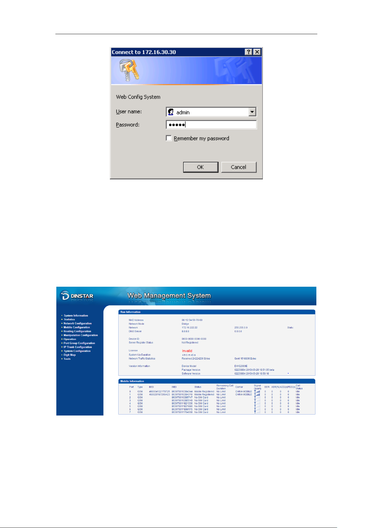
Enter IP address of DWG2000E in IE/Google Chrome. The default IP of LAN port is
192.168.11.1. and the GUI shows as below:
Figure 4-1-1 WEB log interface
_______________________________________________________________________________
Shenzhen Dinstar Technologies Co., Ltd.
12
Page 14
DWG2000E/F/G GSM/CDMA VoIP Gateway User Manual
Enter username and password and then click “OK” in configuration interface. The default
username and password are “admin/admin”. It is strongly recommended, change the default
password to a new password for system security.
4.2 Parameters Configuration
DWG2000E WEB configuration interface consists of the navigation tree and the detail
configuration interfaces.
Figure 4-2-1 WEB introduce
Go through navigation tree, user can check, view modify, and set the device configuration on
the right of configuration interface.
_______________________________________________________________________________
Shenzhen Dinstar Technologies Co., Ltd.
13
Page 15
DWG2000E/F/G GSM/CDMA VoIP Gateway User Manual
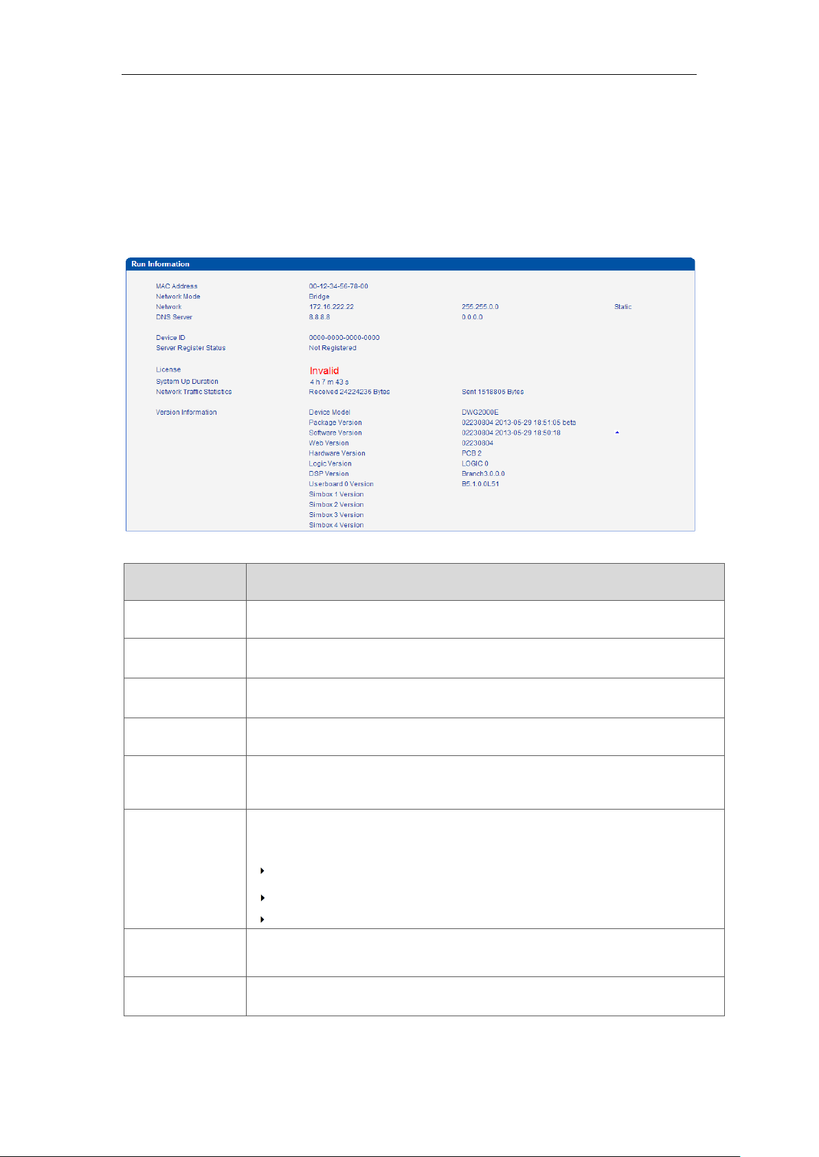
Parameters
Description
MAC Address
Displays the current MAC of the gateway, for example: 00-1F-D6-1B-3D-02
Network Mode
DWG2000E works as bridge mode by default
Network
Current IP address and subnet mask of gateway
DNS Server
Displays DNS server IP address in the same network with the gateway
Device ID
A unique device ID which assigned in factory. This device ID to be used as
register ID with Dinstar SIM cloud.
Server Register
status
Its indicates communicate status with SIMCloud server, there are two type of
status:
Registered
Not Registered
Need Authentication
License
Its indicates device’s license status. Contact with support when it display as
Invalid
System Up Time
Shows the time period of the device running. For example,:1h: 20m, 24s
4.3 System Information
System information interface shows the basic information of status information, Mobile
information and SIP information.
4.3.1 System Information
Figure 4-3-1 system Information
Table 4.3-1 System Information
_______________________________________________________________________________
Shenzhen Dinstar Technologies Co., Ltd.
14
Page 16
DWG2000E/F/G GSM/CDMA VoIP Gateway User Manual
Traffic Statistics
Calculates the net flow, including the total bytes of message received and
sent.
Version info
shows the current firmware version
Device Model: Model name of the device
Package version: 02230804 2013-05-29 18:51:05 beta, 02230804
is the version number
Software version: 02230804 2013-05-29 18:50:18, 02230804 is the
version number
Web version: the version number of web system. The web version
must match with software
Userboard 0 Version: the firmware version of userboard slot 0
Userboard License ID: Contact with support when it display as
Invalid
Hardware version/DSP version/ SIMbox version
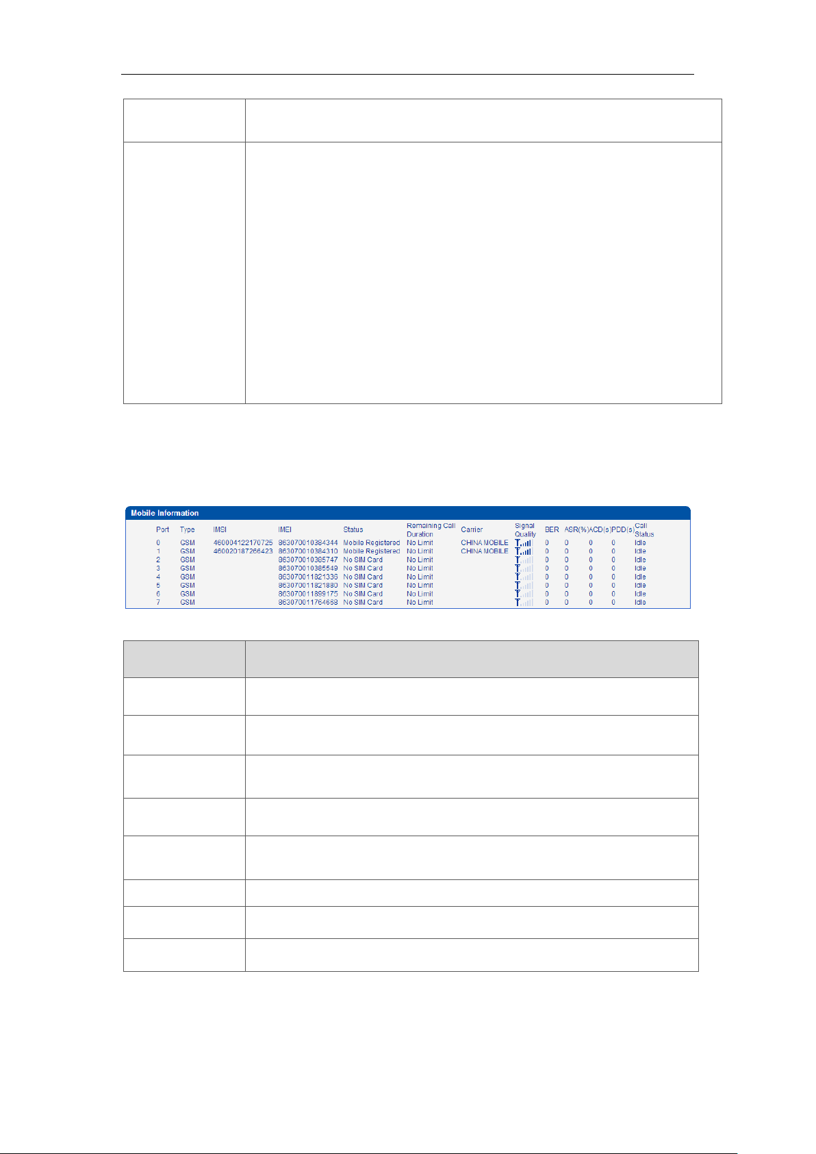
Parameters
Description
Port
Number of GSM/CDMA ports.
Type
Indicates the current type of network. Such as CDMA or GSM
IMSI
International Mobile Subscriber Identity, it is the uniquely identifies of
SIM card
Status
Indicates the connection status of current GSM / CDMA module
Remaining Call
Duration
It showing available total call minutes of SIM card while call limitation is
enabled.
Carrier
Displays the network carrier of current SIM card.
Signal Quality
Displays the signal strength of in each channels of GSM / CDMA.
BER
Its indicate error rates between Module and Base station(BTS)
4.3.2 Mobile Information
Figure 4.3-2 Mobile Information
Table 4.3-2 Mobile Information
_______________________________________________________________________________
Shenzhen Dinstar Technologies Co., Ltd.
15
Page 17
DWG2000E/F/G GSM/CDMA VoIP Gateway User Manual
ASR
Answer Seizure Ratio is a measure of network quality. It’s calculated by
taking the number of successfully answered calls and dividing by the
total number of calls attempted. Since busy signals and other rejections
by the called number count as call failures, the ASR value can vary
depending on user behavior.
ACD
The Average Call Duration (ACD) is calculated by taking the sum of
billable seconds (bill sec) of answered calls and dividing it by the number
of these answered calls.
PDD
Post Dial Delay (PDD) is experienced by the originating customer as the
time from the sending of the final dialed digit to the point at which they
hear ring tone or other in-band information. Where the originating
network is required to play an announcement before completing the call
then this definition of PDD excludes the duration of such
announcements.
Call Status
Show the Status of port, include idle, active, alert and processing
Idle means there is no call on this channel
Processing means call is connecting
Alerting means destination is ringing
Active means the call is connected
Ringing means the gateway is answering incoming call from mobile
Calling Waiting means the gateway is receiving another call during
conversation and implement call waiting service
Call Hold means the call is hold by extension of IPPBX/SIP Server
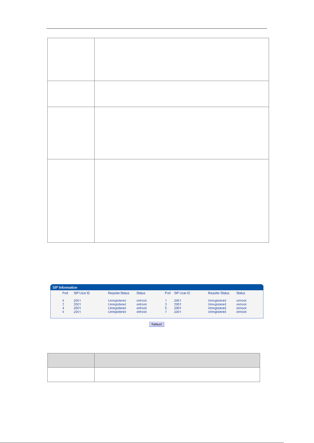
Parameters
Description
Port
The number of SIP channels, DWG2000E-8G/C has 8 SIP channels
4.3.3 SIP Information
Figure 4-3-3 SIP Information
Displays registration status information with Softswitch platform or SIP Server
Table 4-3-3 SIP information
_______________________________________________________________________________
Shenzhen Dinstar Technologies Co., Ltd.
16
Page 18
DWG2000E/F/G GSM/CDMA VoIP Gateway User Manual
SIP User ID
SIP registration account which are provided by the Softswitch and
SIP server
Register Status
Shows the registration status of VoIP channel, including registered
and unregistered.
Status
Show the status of port, Include "onhook" and "offhook"
Parameters
Description
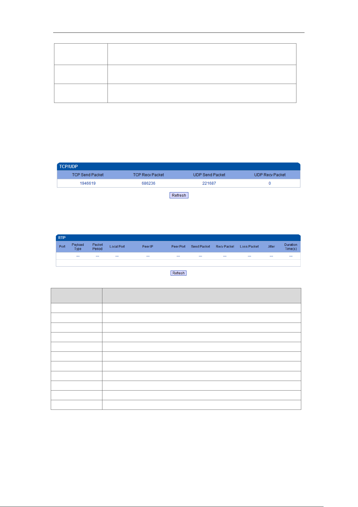
Port
The port of RTP statistics
Payload Type
The voice code of this channel, Include G.723.1/PCMA/PCMU/ G.729AB
Packet Period
Time of packaging
Local Port
Local port of transmitting RTP packages
Peer IP
End of equipment IP address
Peer Port
Peer port of receiving RTP packages
Send Packet
Total of sending RTP packages
Recv Packet
Total of receiving RTP packages
Loss Packet
Total of losing RTP packages
Jitter
Length of delay jitter
Duration Time(s)
Both ends of the call time
4.4 Statistics
4.4.1 TCP/UDP
Figure 4-4-1 TCP/UDP Statistics
4.4.2 RTP
Figure 4-4-2 RTP
Table 4-4-1 Description of RTP Statistics
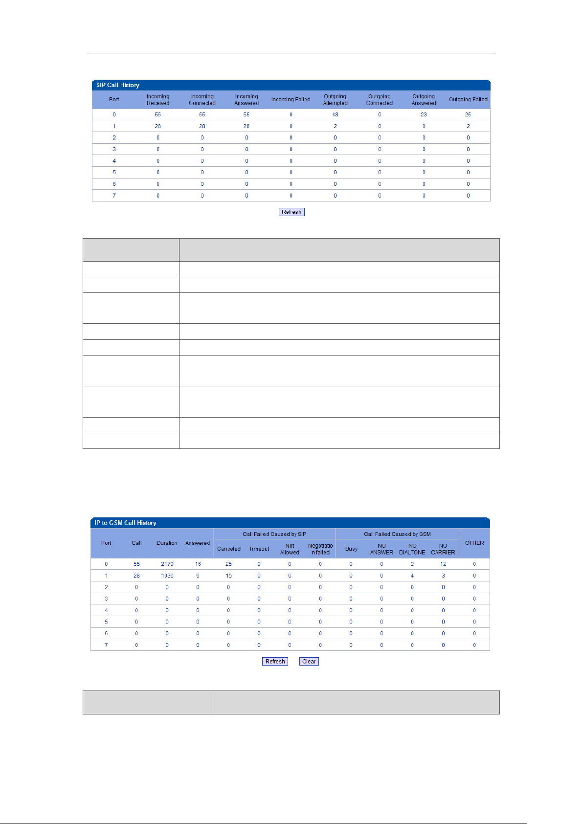
4.4.3 SIP Call History
Figure 4-4-3 SIP Call History
_______________________________________________________________________________
Shenzhen Dinstar Technologies Co., Ltd.
17
Page 19
DWG2000E/F/G GSM/CDMA VoIP Gateway User Manual
Parameters
Description
Port
The port of Call statistics
Incoming Received
The amount of received incoming calls which coming from IP side
Incoming
connected
The amount of incoming calls which have connected
Incoming Answered
The amount of incoming calls which answered by GSM/CDMA module
Incoming Failed
The amount of incoming calls which failed
Outgoing
Attempted
The amount of outgoing calls which attempted to IP side
Outgoing
Connected
The amount of outgoing calls which have connected
Outgoing Answered
The amount of outgoing calls which answered by IP side
Outgoing Failed
The amount of outgoing calls which failed
Parameters
Description
Table 4-4-2 SIP Call History
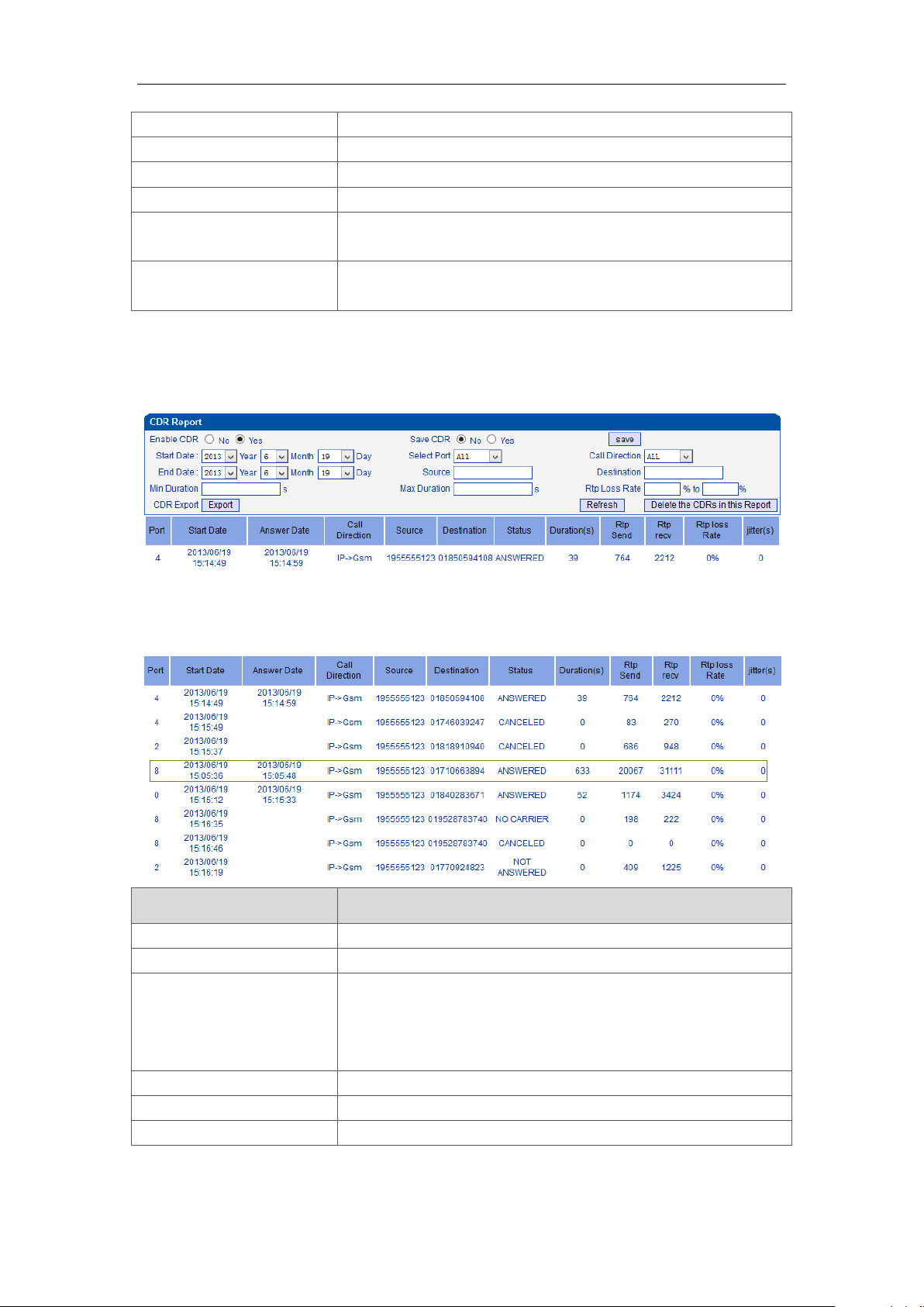
4.4.4 IP to GSM Call History
Figure 4-4-4 IP to GSM Call History
Table 4-4-4 IP to GSM Call History
_______________________________________________________________________________
Shenzhen Dinstar Technologies Co., Ltd.
18
Page 20
DWG2000E/F/G GSM/CDMA VoIP Gateway User Manual
Port
Device GSM port
Call
Statistics the number of calls in this port
Duration
Statistics call total time
Answered
Statistics response times
Call Failed Caused by SIP
Statistics cause of call failure from SIP, include:canceled/
timeout/ not allowed/ Negotiation failed
Call Failed Caused by
GSM
Statistics cause of call failure from GSM, include: Busy/ no
answer/ no dialtone/ no carrier
Parameters
Description
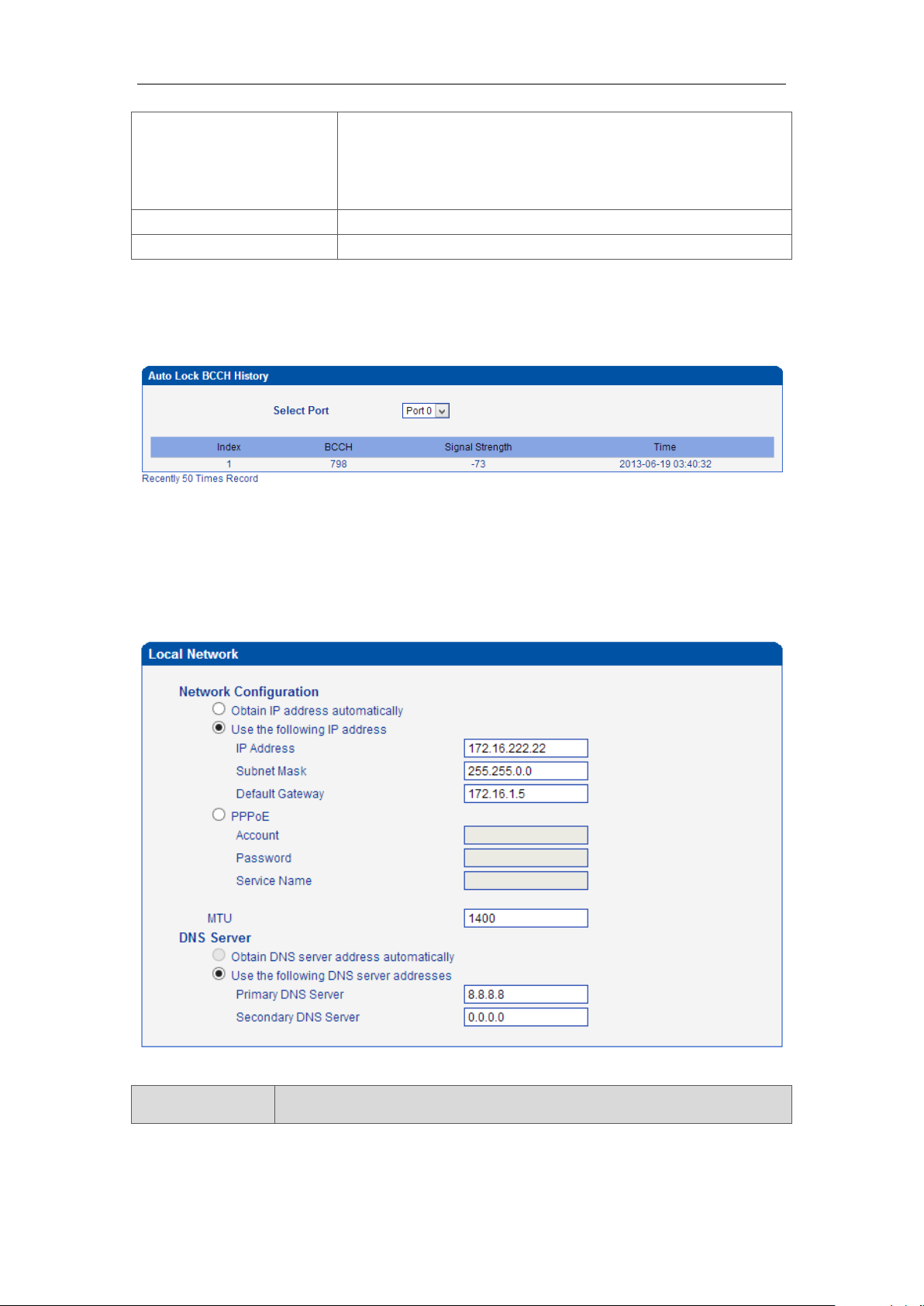
Port
GSM port number
Start Date/Answer Date
start and end time of calls
Direction
IP to GSM:
outbound calls from softswitch/IPPBX to mobile network
GSM to IP:
incoming calls from mobile network to IPPBX/ Softswitch
Source
Calling number
Destination
Called number
Stauts
Answered: the call was established successful
4.4.5 CDR Report
Figure 4-4-5 CDR Report
It is support 10000 CDRs on gateway. The CDRs will lost after reboot while save CDR set to
No. To make the device works in good performance,we are strongly recomand to set ’Save
CDR’ to No.
_______________________________________________________________________________
Shenzhen Dinstar Technologies Co., Ltd.
19
Page 21
DWG2000E/F/G GSM/CDMA VoIP Gateway User Manual
Canceded: the call was canceled by calling party
No Carrier: the call was rejected by mobile network
Not Answered: no body to answer the call
Busy: user busy
Durations
Call duration of the call
RTP send/recv/loss rate
RTP Statistics of the call
Parameters
Description
4.4.6 Auto Lock BCCH History
Figure 4-4-6 Auto Lock BCCH History
It is record history of BCCH to help analysis SIM card register status.
4.5 Network Configuration
4.5.1 Local Network
Figure 4-5-1 Local Network
_______________________________________________________________________________
Shenzhen Dinstar Technologies Co., Ltd.
Table 4-5-1 Local network
20
Page 22
DWG2000E/F/G GSM/CDMA VoIP Gateway User Manual
Obtain IP Address
Automatically
Enable the device obtain IP Address automatically or not. Default is
enabling
Use the Following
IP Address
Configure the "IP Address", "Subnet Mask" and "Default Gateway" by
manual
PPPoE
Need ISP offer the account and password, Use this mode when there is
not router in the local network
MTU
Message transmit unit, default is 1400
Obtain DNS
Server Address
Automatically
When enable the WAN port option of "Obtain DNS Server Address
Automatically”, which will be enabled subsequently.
Use the Following
DNS Server
Addresses
Fill in the IP address of "Primary DNS Server" and "Secondary DNS
Server"
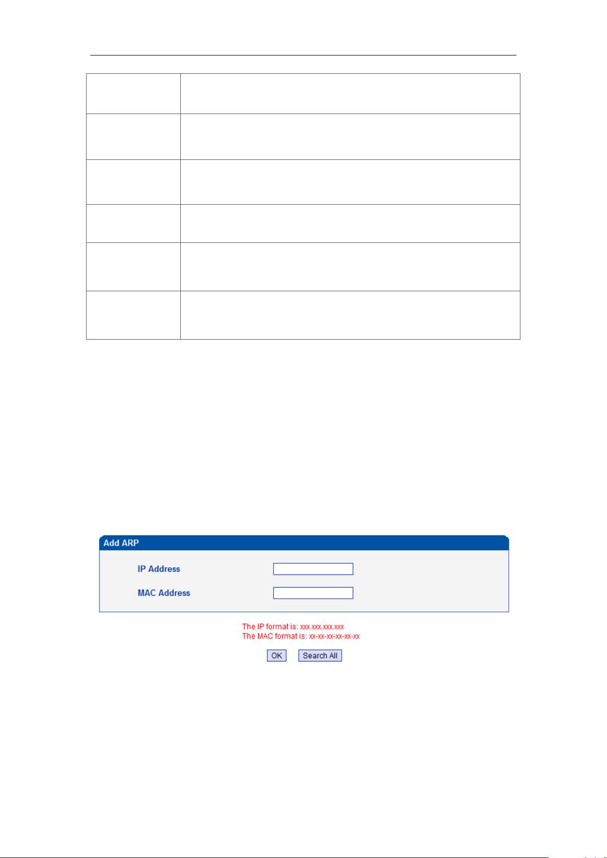
4.5.2 ARP
The ARP function mainly used to query and add the map of IP and MAC. There are static or
dynamic ARP entries.
Like other routers, the gateway can automatically find the network device on the same
segment. But, sometimes you don't want to use this automatic mapping; you'd rather have
fixed (static) associations between an IP address and a MAC address. Gateway provides you
the ability to add static ARP entries to:
Protect your network against ARP spoofing
Prevent network confusion as a result of misconfigured network device
Figure 4-5-3 Add ARP
Click Search All to check ARP buffer.
_______________________________________________________________________________
Shenzhen Dinstar Technologies Co., Ltd.
21
Page 23
DWG2000E/F/G GSM/CDMA VoIP Gateway User Manual
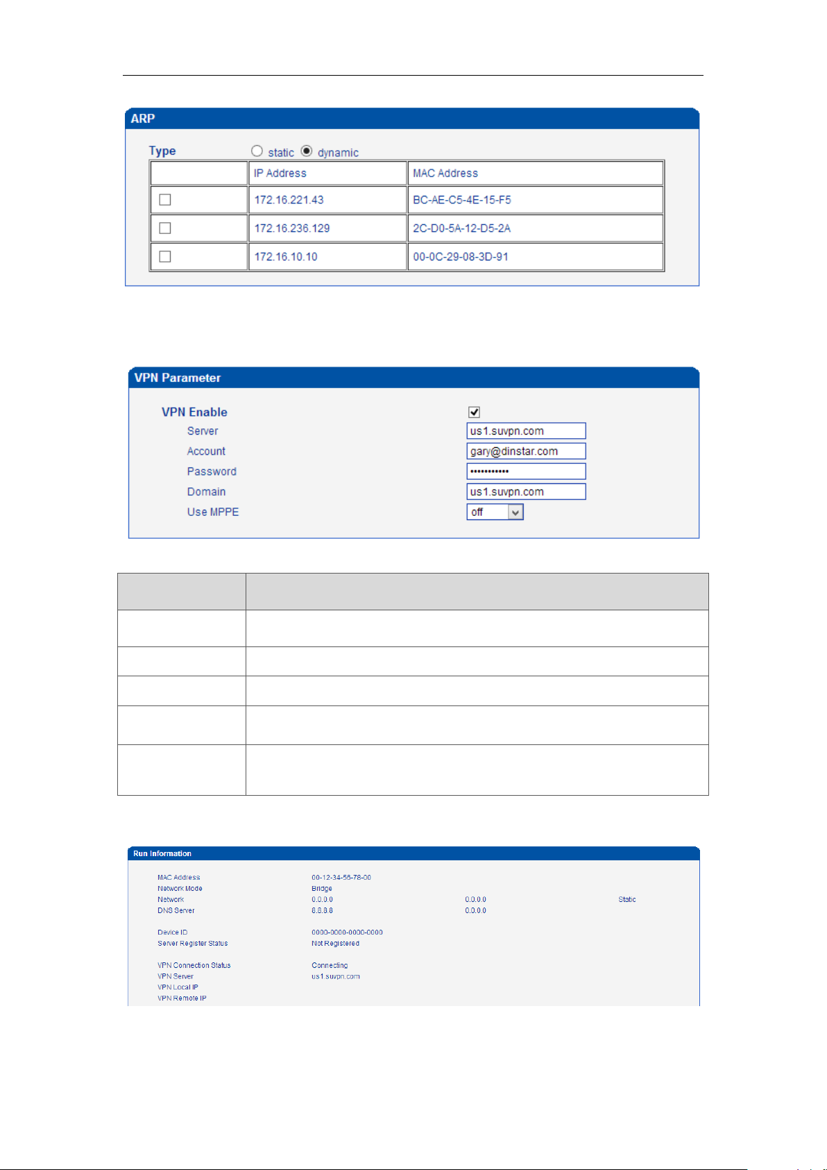
Parameters
Description
Server
VPN Server IP or domain name(support PPTP only)
Account
VPN account which provide by server or VPN provider
Password
Password of VPN which provide by server or VPN provider
Domain
Follow VPN setting, can be null
Use MPPE
Encryption parameter, support 40/128 bit, must be match with VPN
server
4.5.3 VPN Parameter
Figure 4-5-3 VPN Parameter
Table 4-5-3 Description of VPN Parameter
Check VPN connecting status on system information
_______________________________________________________________________________
Shenzhen Dinstar Technologies Co., Ltd.
22
Page 24
DWG2000E/F/G GSM/CDMA VoIP Gateway User Manual
Parameters
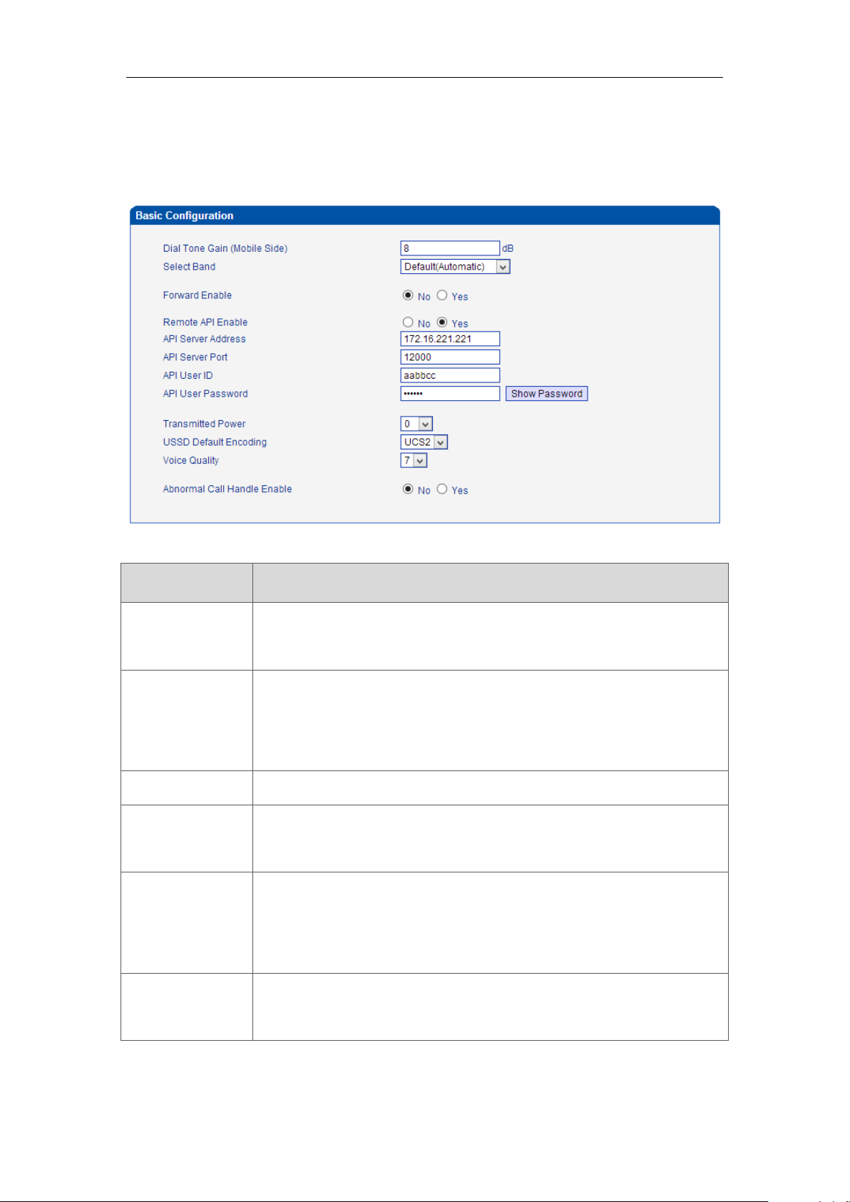
Description
Dial Tone Gain
It is the dial tone volume of call waiting, dial tone of mobile module when
call out. Usually adopt the default configuration.
Select Band
According to carrier’s band standards. Standards are as bellow:
GSM: 850/900/1800/1900 MHz
Notes: it is take effective for GSM only
Forward Enable
When port occupied whether allow call forwarding
Forward Master
Mobile
Choose the destination port to be forwarded
Remote API
Enable
API is an opened protocols which provide to users to develop third party
application software such as bulk SMS, SIM card management etc. The
default is "No".
API Server
Address
It is the remote IP address of application software/ API server. This is an
option when selecting "Yes" under 'remote API enable".
4.6 Mobile Configuration
4.6.1 Basic Configuration
Figure 4-6-1Basic Configuration
Table 4-6-1 Description of Basic Configuration
_______________________________________________________________________________
Shenzhen Dinstar Technologies Co., Ltd.
23
Page 25
DWG2000E/F/G GSM/CDMA VoIP Gateway User Manual
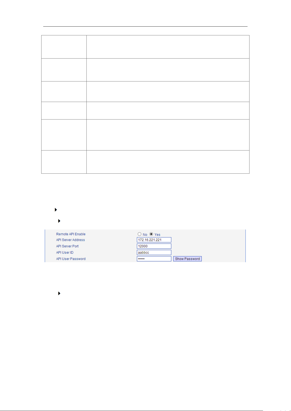
API Server Port
To define communicate port between gateway and API server. This is an
option when selecting "Yes" under "remote API enable"
API User
ID/Password
To define authentication user name and password between gateway and
API server.
Transmitted
Power
Transmit power of module. Use the default setting value and contact with
technical support if need to change it.
USSD Defaulting
Encoding
Encoding of USSD, default is UCS2.
Voice Quality
Keep the parameter as default except the device is facing low ASR issue.
To adjust voice quality level possibly help to improve low ASR issue but
may affect voice quality.
Abnormal Call
handle
It is an optional parameter to handle abnormal calls.
Notes: please reference API document for more details.
Example:
Configuration between SMS box and gateway
Configure API parameters on gateway
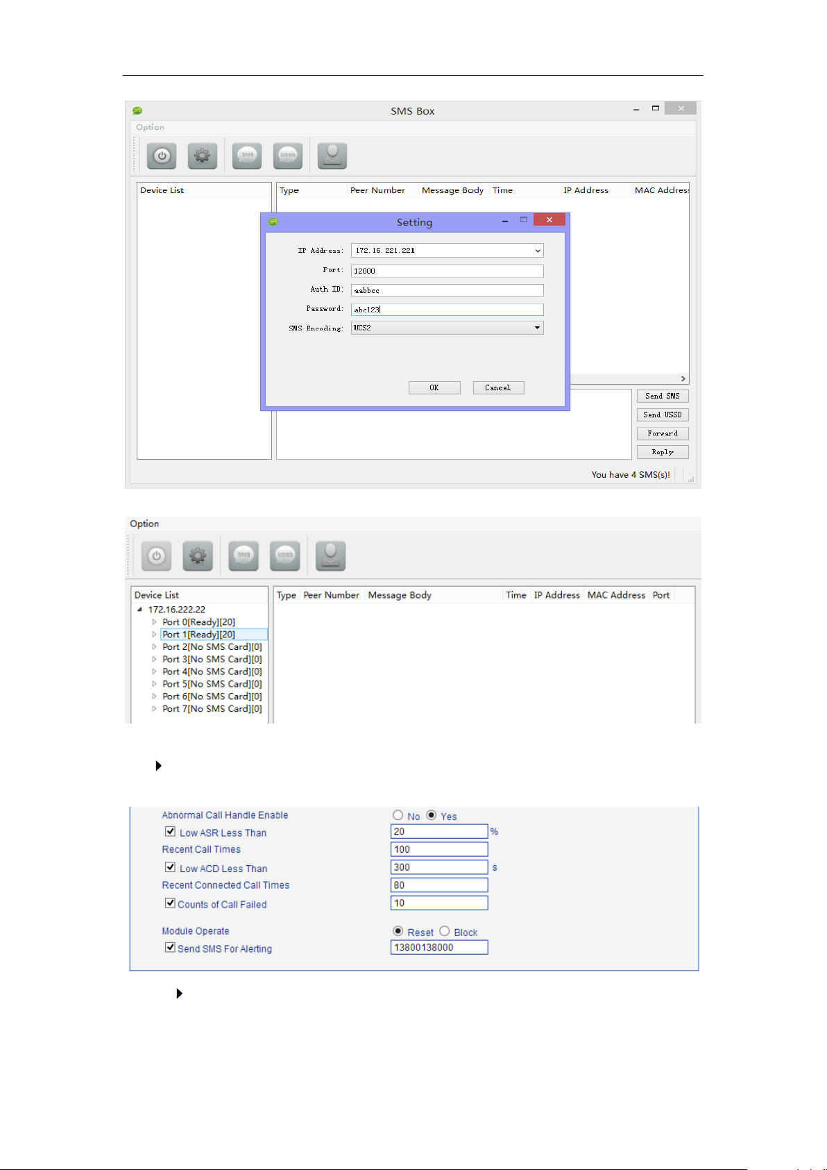
The IP server which installed SMS box software is 172.16.221.221, pre-set Port 12000,
User ID aabbcc and password abc123 as example.
Configure SMS box
(Next Page)
_______________________________________________________________________________
Shenzhen Dinstar Technologies Co., Ltd.
24
Page 26
DWG2000E/F/G GSM/CDMA VoIP Gateway User Manual
Then click OK and start service, the gateway IP will be presented in device list of SMS box
how to configure abnormal call on gateway
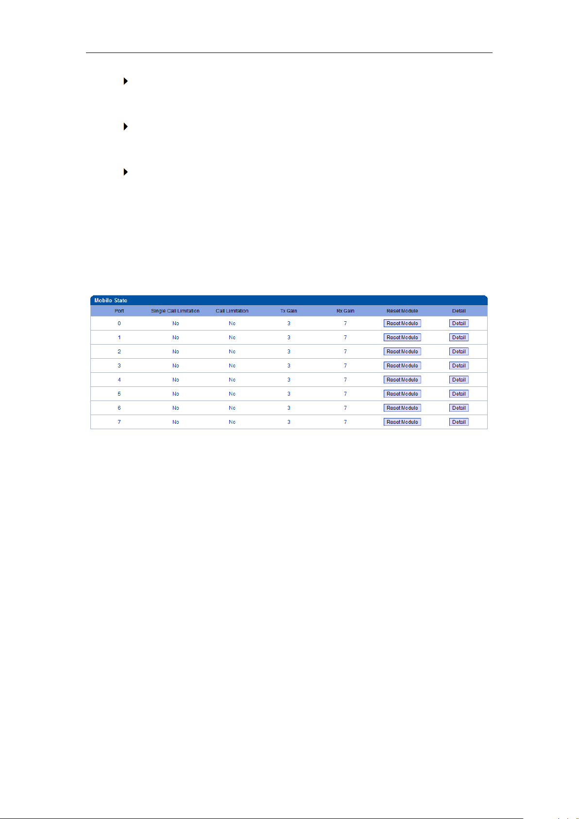
Here is example of abnormal call setting
Low ASR Less Than 20%
statistics 100 calls, auto-reset/block module while ASR less than 20%
_______________________________________________________________________________
Shenzhen Dinstar Technologies Co., Ltd.
25
Page 27
DWG2000E/F/G GSM/CDMA VoIP Gateway User Manual
Low ACD Less Than 300s
statistics 80 calls, auto-reset/block module while ACD less than 300 seconds
Counts of Call Failed
auto-reset block module while 10 times fail to call to mobile network continuously
Mobile Operate
reset module to register again to mobile network. Block means won’t call out via
this module any more unless unblock it
4.6.2 Mobile Configuration
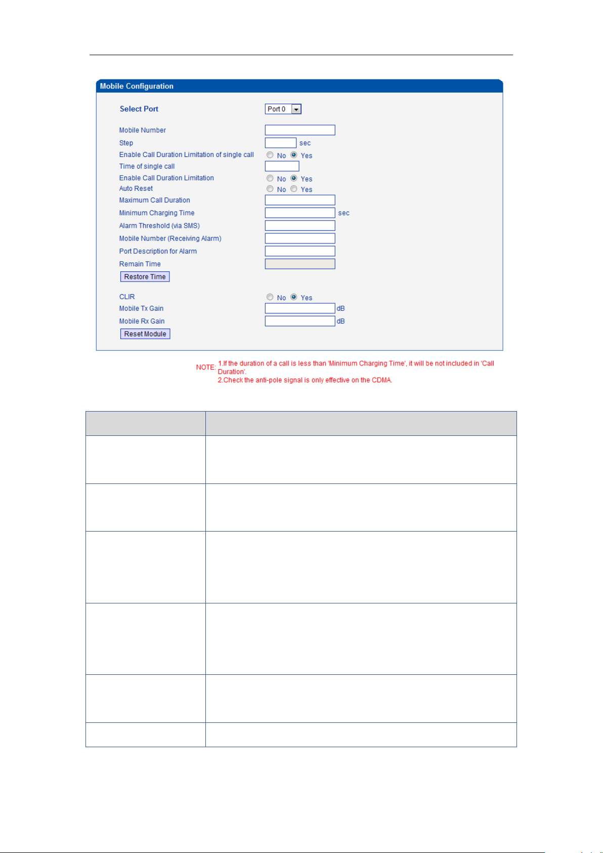
Figure 4-6-2 Mobile State
Figure 4-6-3 Mobile Configuration
_______________________________________________________________________________
Shenzhen Dinstar Technologies Co., Ltd.
26
Page 28
DWG2000E/F/G GSM/CDMA VoIP Gateway User Manual
Parameters
Description
Mobile Number
SIM card number of the channel. That must be configured when
“Forward” function enable.
Step
Step length value range is 1-120 s, step length multiplied by time of
single call just said a single call duration time allowed.
Enable Call Duration
Limitation single call
Define maximum call duration for single call.
Example: if Time of single call set to 10, the call will be
disconnected after talking 10*step seconds
Time of single call
The value of limitation single call, this value range is 1-65535. Step
length multiplied by time of single call just said a single call duration
time allowed.
Enable Call Duration
Limitation
This function is to limit the max call duration of channel. The max
call duration is between 1 to 65535 steps.
Auto reset
Set a time make device reboot
Table 4-6-2 Description of Mobile Configuration
_______________________________________________________________________________
Shenzhen Dinstar Technologies Co., Ltd.
27
Page 29

DWG2000E/F/G GSM/CDMA VoIP Gateway User Manual
Maximum Call Duration
Defines a value by users. That will limit the SIM/UIM card’s total call
duration. After the call duration excesses this value, no call will be
made from this channel. The value range is 1-65535. If user
doesn’t configure this value, Default is no max call duration limits
for this channel.
Minimum Charging
Time
A minimum charging time (in seconds) is defined during which no
charging is done at carrier side. If the conversation time is even
shorter, the total call duration will not decrease.
Alarm Threshold(via
SMS)
When the SIM remain time is or less than this value, DWG will send
the alarm SMS to remind the users of the SIM remain time.
Mobile Number
(Receiving Alarm)
The mobile phone No. which used to receive the alarm SMS. Users
can get SMS report of SIM/UIM card status (SIM Remain Time) in
DWG.
Port Description for
Alarm
It is the identification mark of SIM/UIM card in the SMS report. The
mobile phone No. of the SIM/UIM card is recommended to use as
the port description for alarm, or any other string.
Remain Time
Indicates the current SIM remain time. It can’t modified
Restore time
Recovers the SIM remain time to initial value, the Maximum Call
Duration.
CLIR
Caller ID display restrict. This function is used to restrict the mobile
phone No. By adding “#31#” before the mobile phone ID, this
function should be supported by carrier.
Mobile Tx Gain
Transits gain of the mobile module, from IP side to PSTN side.
Mobile Rx Gain
Receives gain of the mobile module, from PSTN side to IP side.
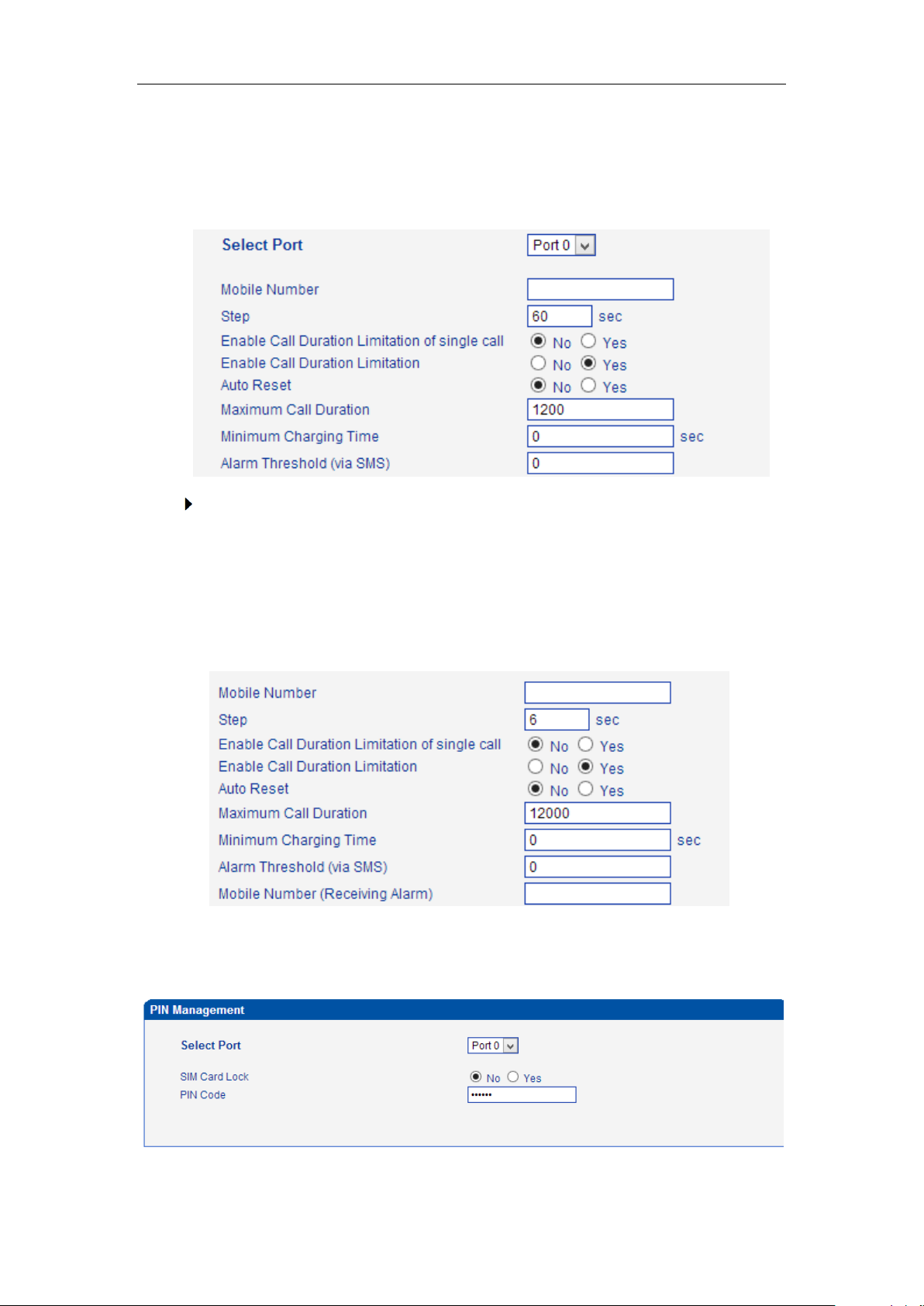
How to configure maximum call limitation
Preset: 1200 minutes (Ct) for each SIM
Case1. The SIM card billing every 60s (Cu)
So we have to configure maximum call duration as below:
_______________________________________________________________________________
Shenzhen Dinstar Technologies Co., Ltd.
28
Page 30
DWG2000E/F/G GSM/CDMA VoIP Gateway User Manual
Step = Cu = 60s;
Maximum Call Duration = total call minutes of SIM (minutes) * 60s / step = Ct * 60 /
Cu =1200 * 60 / 60 = 1200 step
Case2. The SIM card billing every 6s (Cu)
So we have to configure maximum call duration as below:
Step = Cu = 6s
Maximum Call Duration = total call minutes of SIM (minutes) * 60s / step = Ct *60 /
Cu = 1200 *60 / 6 =12000 step
4.6.3 PIN Management
Figure 4-6-4 PIN Management
_______________________________________________________________________________
Shenzhen Dinstar Technologies Co., Ltd.
29
Page 31
DWG2000E/F/G GSM/CDMA VoIP Gateway User Manual
Parameters
Description
PIN
Personal identification number of SIM card. In the status of SIM card
locked, PIN can be modified to prevent SIM card from being stolen.
Select Port
Selects the GSM/CDMA channel number
Parameters
Description
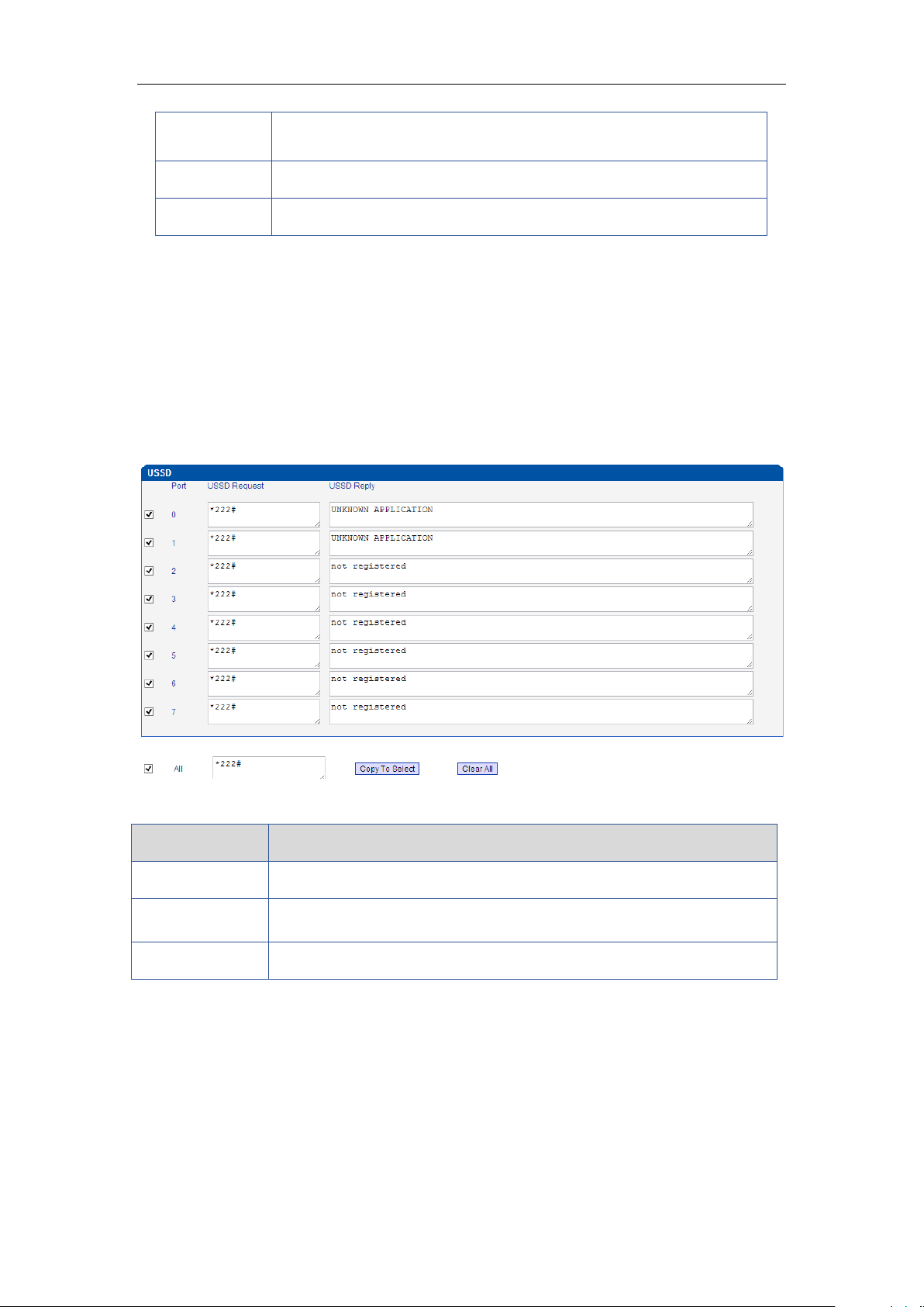
Select Port
Users can select a defined channel or random channel to send SMS.
Input the receiver’s mobile phone No to send SMS.
Table 4-6-3 Description of PIN Management
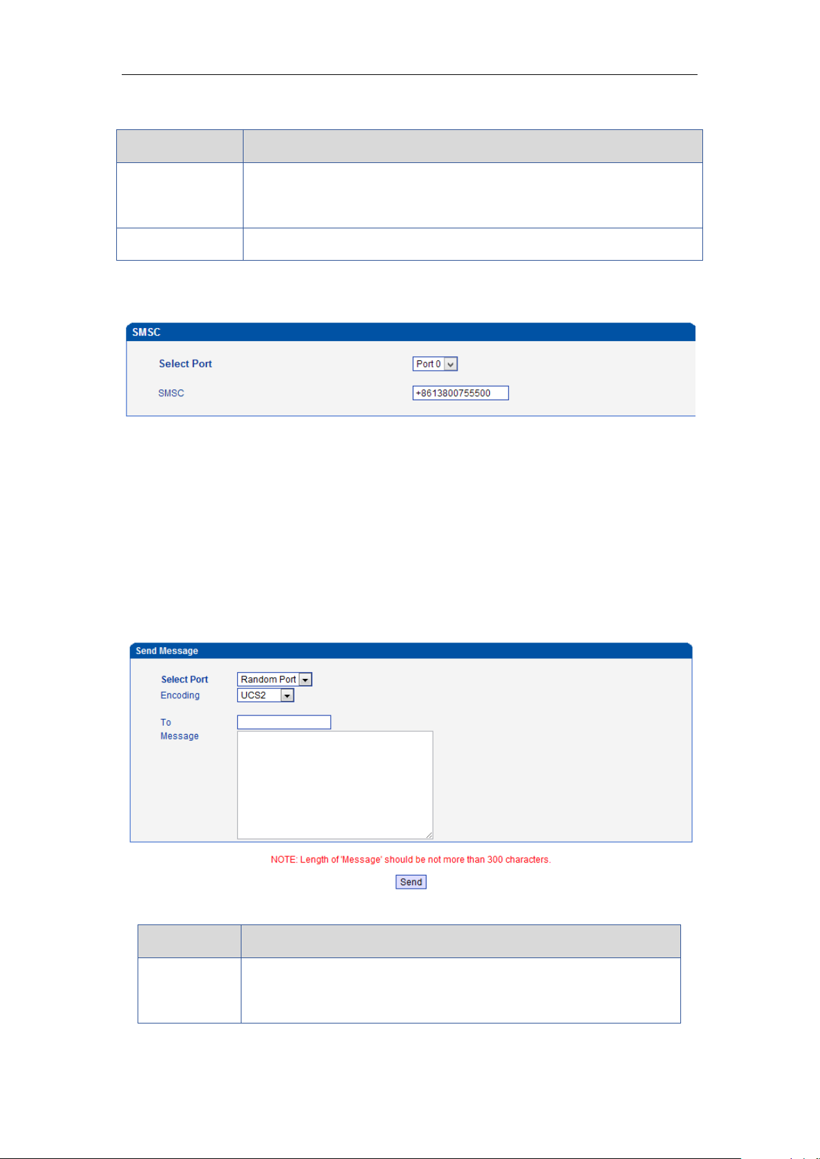
4.6.5 SMSC
Figure 4-6-5 SMSC
SMS center of mobile, in most places, the celluar module will automatically detect the SMSC
number. This configurable option is used in a situation that the SMSC number could not
detected by celluar module. When such case happens, please contact with mobile service
provider to identify the SMSC number and then add SMSC number in SMSC configurable web
interface.
4.6.6 Send SMS/Recv SMS
Figure 4-6-6 Send SMS
Table 4-6-5 Description of SMS sending
_______________________________________________________________________________
Shenzhen Dinstar Technologies Co., Ltd.
30
Page 32
DWG2000E/F/G GSM/CDMA VoIP Gateway User Manual
Encoding
Two kinds of message encoding under PDU models, 7-bit encoding
and UCS2 encoding. Default is UCS2.
To
Mobile phone No. of the receiver
Message
Content of the SMS. The length is limited to 300 characters.
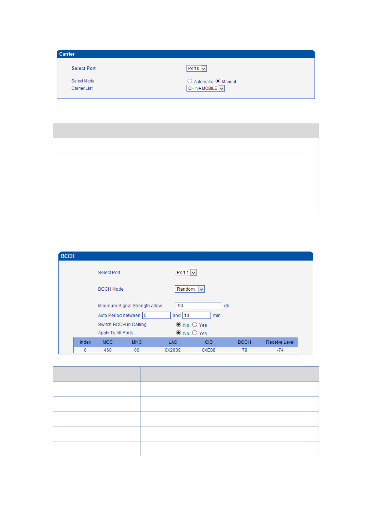
Parameters
Description
Port
Select the GSM channel to send USSD
USSD Reply
Display results of USSD
USSD Request
Display the result of sending USSD
4.6.7 USSD
USSD (Unstructured Supplementary Service Data) is a Global System for Mobile(GSM)
communication technology that is used to send text between a mobile phone and an
application program in the network. Applications may include prepaid roaming or mobile
chatting.
Figure 4-6-7 USSD
Table 4-6-6 Description of USSD
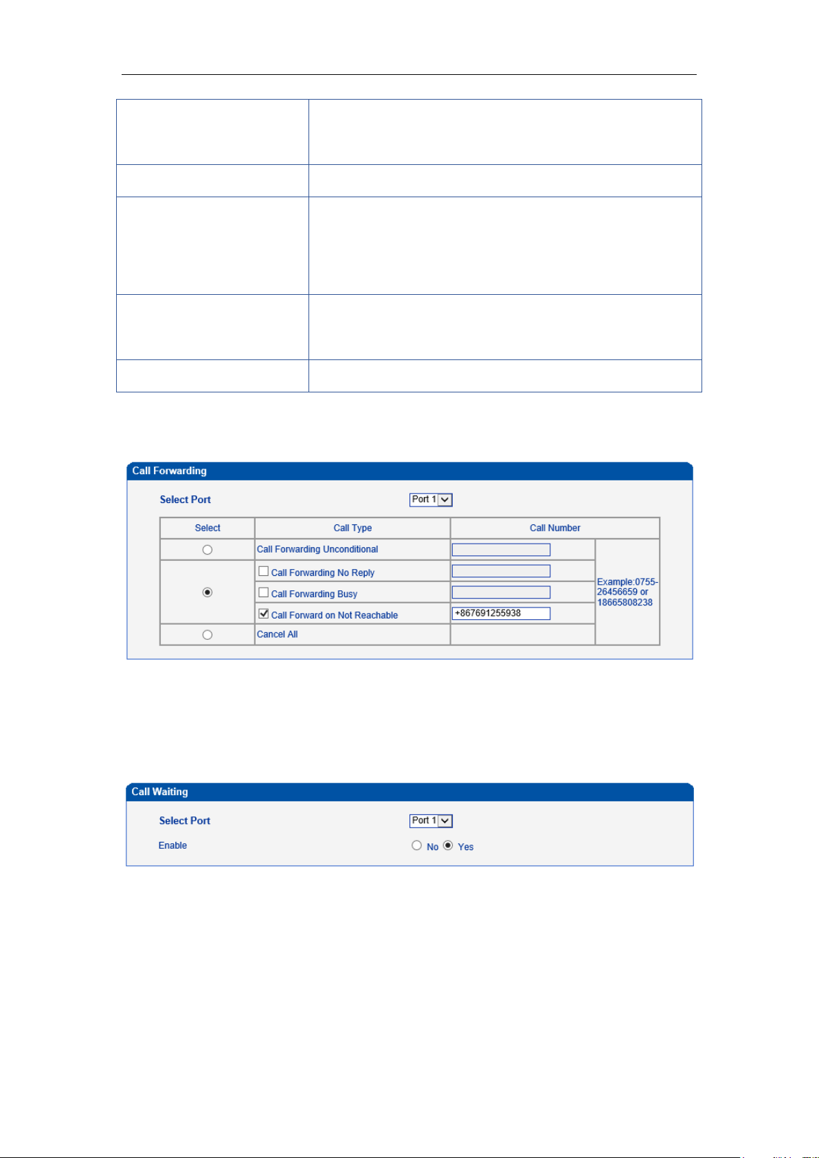
4.6.8 Carrier
Figure 4-6-8 Select Carrier
_______________________________________________________________________________
Shenzhen Dinstar Technologies Co., Ltd.
31
Page 33
DWG2000E/F/G GSM/CDMA VoIP Gateway User Manual
Parameters
Description
Select Port
Select GSM channel, default Port 0
Select Mode
There are two modes to select carrier automatic and manual.
Automatic mode can be automatically search operators. Manual mode
can choose operators from the carrier list.
Carrier List
If you select manual mode, you can select carrier from carrier list.
Parameters
Description
BCCH Mode
There are four options. Default, Fixed, Random, Advanced
Refresh Interval
Set frequency detection refresh time
Auto Refresh/Stop Refresh
Choose whether to refresh frequency
Index
Serial number
MCC
Mobile country code, China is 460
This function is used to select carrier.
Table 4-6-6 Description of select Carrier
4.6.9 BCCH
Figure 4-6-9 BCCH
Table 4-6-7 Description of BCCH
_______________________________________________________________________________
Shenzhen Dinstar Technologies Co., Ltd.
32
Page 34
DWG2000E/F/G GSM/CDMA VoIP Gateway User Manual
MNC
Mobile network code, used to distinguish between different
network operators
LAC
Location area codes
CID
Cell ID (CID) is a generally unique number used to identify
each Base transceiver station (BTS) or sector of a BTS within
a Location area code (LAC) if not within a GSM network.
BCCH
broadcast control channel (BCCH) is a point to multipoint,
unidirectional (downlink) channel used in the Um interface of
the GSM cellular standard
Receive Level
Receiving signal strong strength
Choose a frequency to lock the operations.
4.6.10 Call Forwarding
Call forwarding is the same as mobile phone which to activate/deactivate
supplementary service of SIM card. For more details of these services, please contact to
local providers.
4.6.11 Call Waiting
Call waiting is the same as mobile phone which to activate/deactivate supplementary
service of SIM card. For more details of these services, please contact to local providers.
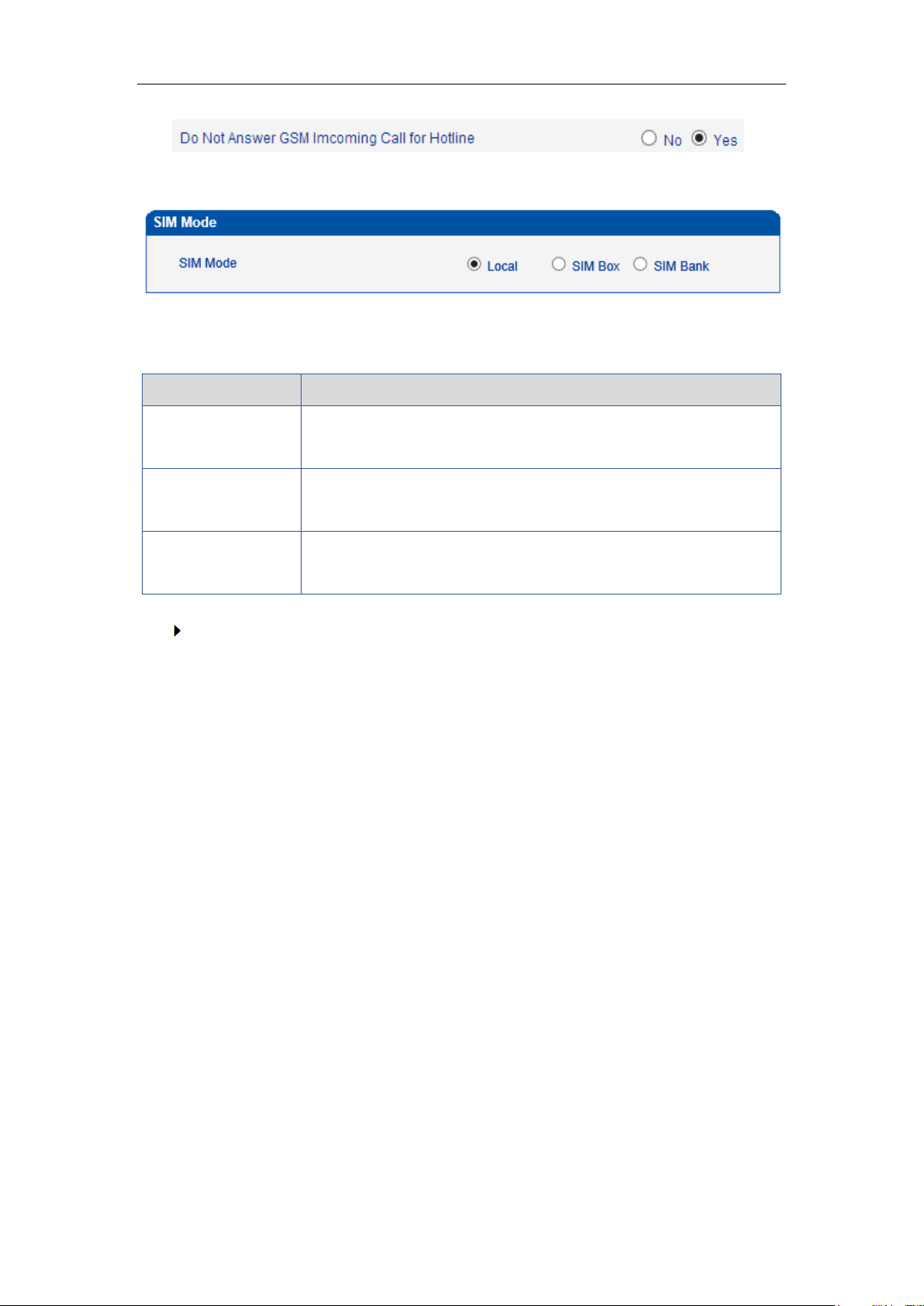
Notes: Call waiting is only take effective while “Do Not Answer GSM Incoming Call for
Hotline” set to Yes.
System configuration -> Service Parameter
_______________________________________________________________________________
Shenzhen Dinstar Technologies Co., Ltd.
33
Page 35
DWG2000E/F/G GSM/CDMA VoIP Gateway User Manual
Item
Description
Local
To use local SIM card which install on gateway, this way is most
common used by many of users
SIM Box
SIM Box is a small box which use for SIM card storage. It ideal for
users who want replace SIM card frequently
SIM Bank
SIM Bank is use for SIM card storage and remote SIM management
together with Dinstar SIM Cloud
4.6.12 SIM Mode
Dinstar gateway support two types of SIM card installation, which is local and remote SIM
management.
What’s the difference between SIM Box and SIM Bank?
Both SIM Box and SIM Bank are used for SIM storage. SIM Box is a simple device
which use for remote SIM installation only but not support SIM rotation, NAT traversal
etc. it is work with local network only that means gateway and SIM Box must be
connected to the same network.
Compare to SIM Box, SIM Bank is most powerful and provide flexible SIM
management rules such as SIM Rotation, SIM switching and anti-block policy. It is
important component of Dinstar SIM cloud solution. With SIM Bank, GSM gateways
can be deployed in different locations and countries so that the user are able to
supervise all SIMs in one place.
_______________________________________________________________________________
Shenzhen Dinstar Technologies Co., Ltd.
34
Page 36
DWG2000E/F/G GSM/CDMA VoIP Gateway User Manual
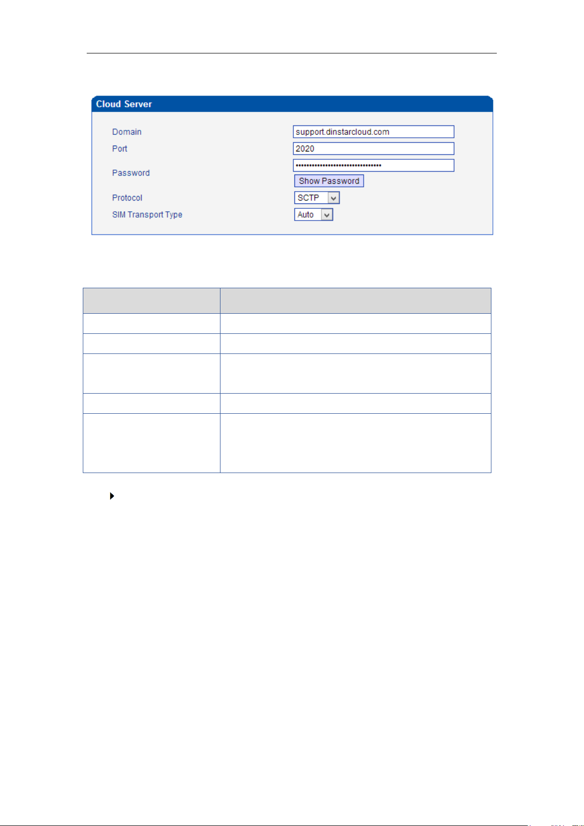
Parameters
Description
Domain
Unique domain for the users
Port
It is define by SIM Cloud. Default value is 2020
Password
It is create when add gateway on SIM Cloud. The password
is use to authentication purpose
Protocol
SCTP, UDP
SIM Transport Type
Auto: the device is chose transport method automatically;
Relay:SIM Server work as relay server, all data must be
transport by SIM server.
4.6.13 Cloud Server
The Cloud server is normally configured when the gateway work with SIM Bank or centralized
management purpose.
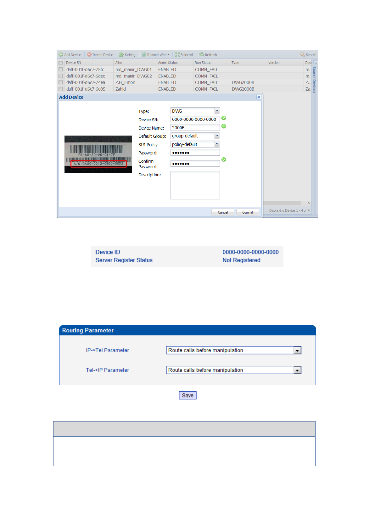
How to register gateway to SIM Cloud?
Example: add gateway on domain support.dinstarcloud.com
_______________________________________________________________________________
Shenzhen Dinstar Technologies Co., Ltd.
35
Page 37
DWG2000E/F/G GSM/CDMA VoIP Gateway User Manual
Parameters
Description
Tel->IP Parameter
Global parameters, it will take effect while number manipulation
configured
Device S/N is the device ID on gateway, find it on the page system information, as
below:
4.7 Routing Configuration
4.7.1 Routing Parameter
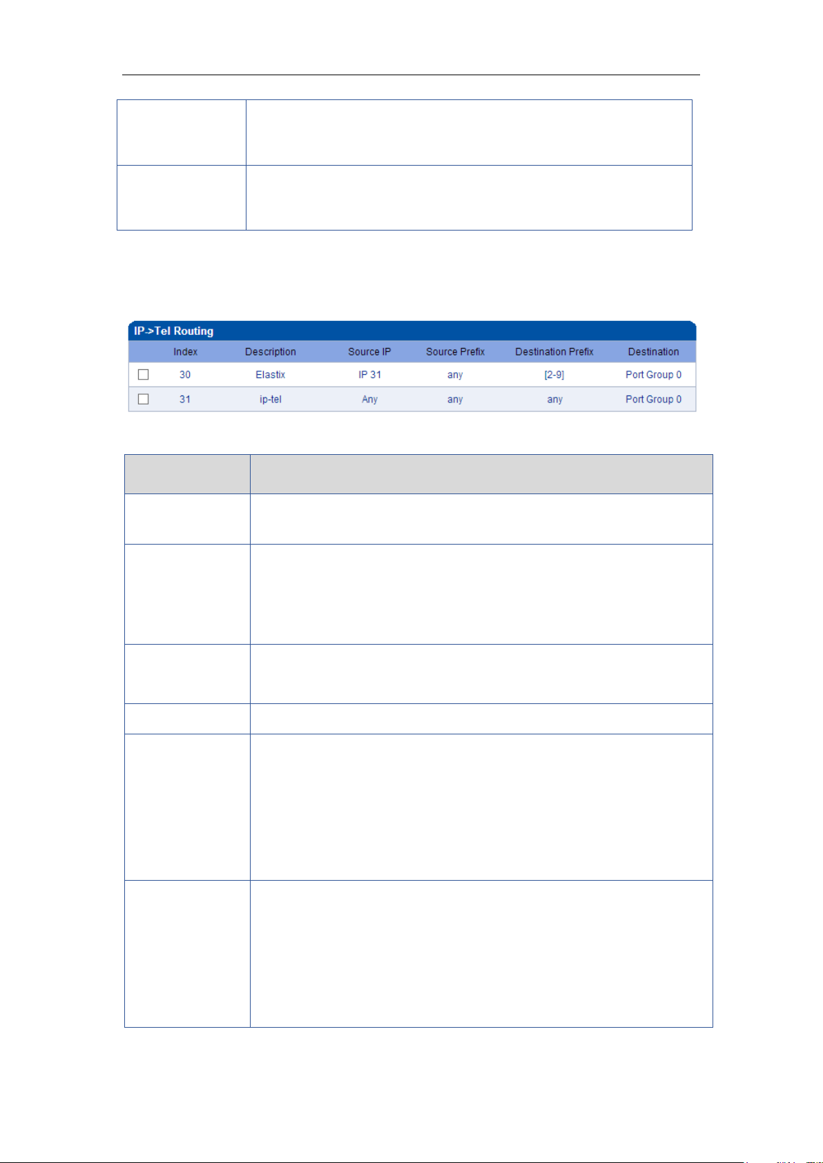
Figure 4-7-1 Routing Parameter
Table 4-7-1Description of Routing Parameter
_______________________________________________________________________________
Shenzhen Dinstar Technologies Co., Ltd.
36
Page 38
DWG2000E/F/G GSM/CDMA VoIP Gateway User Manual
Route calls after
manipulation
The parameters indicate that the gateway will select Tel->IP routes
after number manipulation completed
Route calls before
manipulation
The parameters indicate that the gateway will select Tel->IP routes
before number manipulation completed
Parameters
Description
IP ->Tel Routing
This item uses to configure outgoing call routes which can be used for
receive the calls from the IP side
Index
It uniquely identifies a route. Its value is assigned globally, ranging from 0
to 31. The route preferentially match the rules which the value of index is
smaller. Index 31 is default route on gateway which to be match all
prefixes.
Description
It describes the route for the ease of identification. Its value is character
string
Source IP
It specifies the IP of the caller
Source Prefix
All the caller number must match the source prefix. It specifies the source
prefix allow to send call out
Any: include anonymous, 0xxxx, 1[2-9]xxxx etc.
0xxxx: consist of some digits such as 015,08,09
1[3-8]6:consist of some prefix, include 136,146,156,166,176, 186
Destination Prefix
All the called number must match the destination prefix, the call prefix
indicates the connected number
Any: include anonymous, 0xxxx, 1[2-9]xxxx etc.
0xxxx: consist of some digits such as 015,08,09
1[3-8]6:consist of some prefix, include 136,146,156,166,176, 186
4.7.2 IP->Tel Routing
Figure 4-7-2 IP to Tel Routing
Table 4-7-2 Description of IP to Tel Routing
_______________________________________________________________________________
Shenzhen Dinstar Technologies Co., Ltd.
37
Page 39
DWG2000E/F/G GSM/CDMA VoIP Gateway User Manual
Destination
Its specifies destination Port or Port Group
Parameters
Description
Tel -> IP Routing
This item uses to configure incoming call routes which can be used
for receive the calls from the mobile.
Index
It uniquely identifies a route. Its value is assigned globally, ranging
from 0 to 31.The route preferentially match the rules which the value
of index is smaller
Description
It describes the route for the ease of identification. Its value is
character string
Source Port
It specifies the Port or Port Group which will receive the calls from
mobile
Source Prefix
All the caller number must match the source prefix. It specifies the
source prefix allow to send call out
Any: include anonymous, 0xxxx, 1[2-9]xxxx etc.
0xxxx: consist of some digits such as 015,08,09
1[3-8]6:consist of some prefix, include 136,146,156,166,176, 186
Destination Prefix
All the called number must match the destination prefix, the call prefix
indicates the connected number
Any: include anonymous, 0xxxx, 1[2-9]xxxx etc.
0xxxx: consist of some digits such as 015,08,09
1[3-8]6:consist of some prefix, include 136,146,156,166,176, 186
Destination
Its specifies destination IP trunk or SIP server
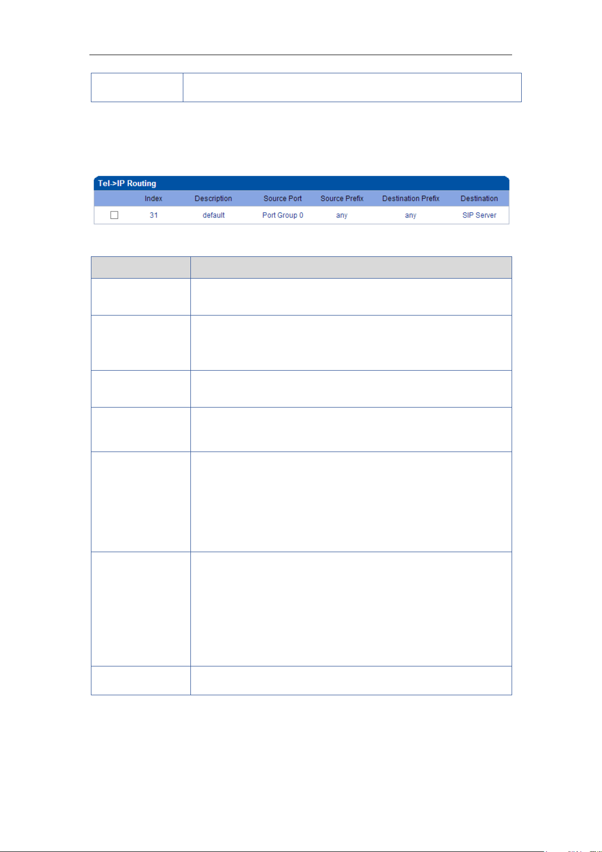
4.7.3 Tel->IP Routing
Figure 4-7-3 Tel to IP Routing
Table 4-7-3 Description of Tel to IP Routing
Figure 4-7-4 Tel to IP routing Modify
_______________________________________________________________________________
Shenzhen Dinstar Technologies Co., Ltd.
38
Page 40
DWG2000E/F/G GSM/CDMA VoIP Gateway User Manual
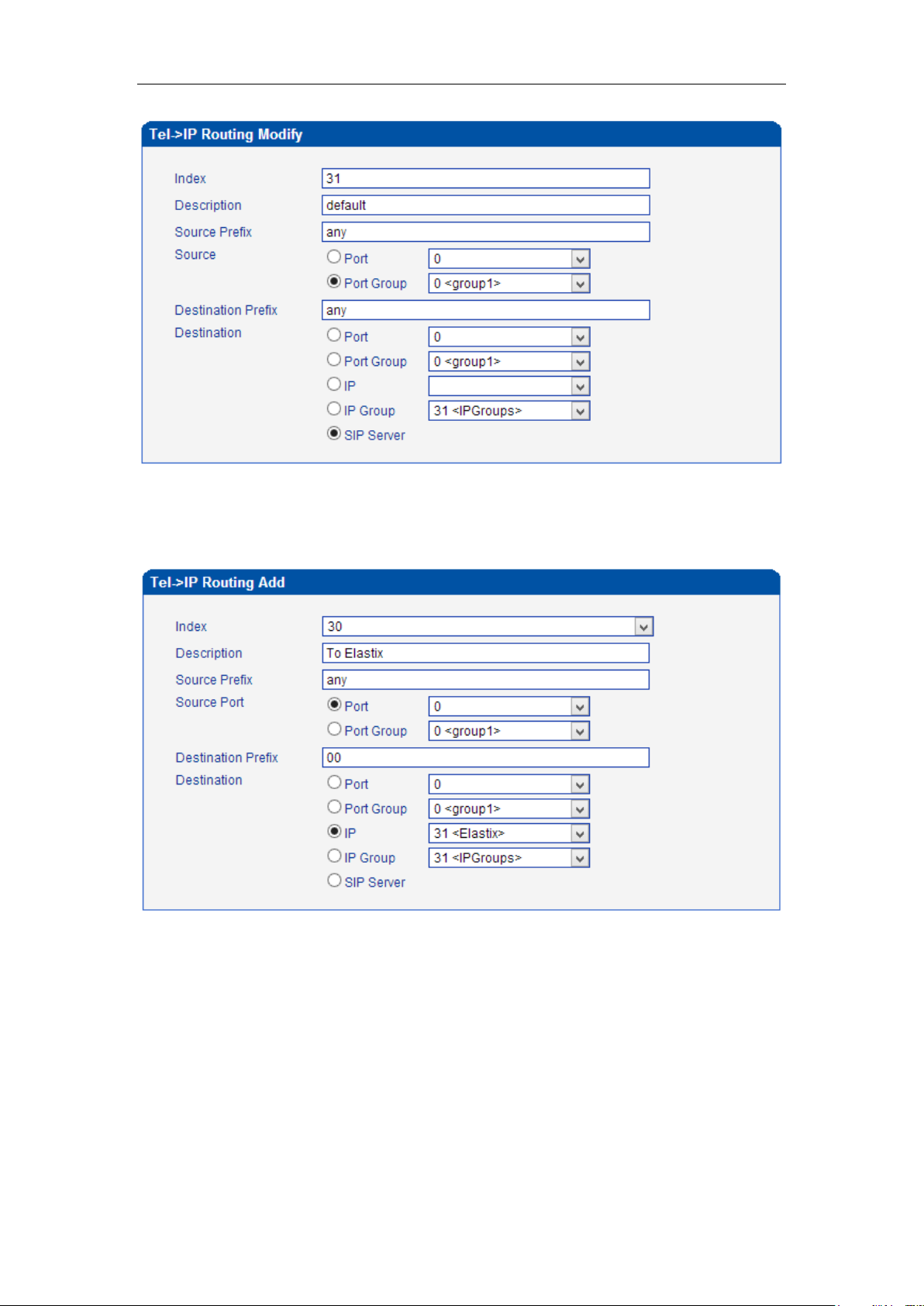
It's a default route configured in gateway. It allows any number from source port 0 send
call to SIP server with any prefix.
Figure 4-7-5 Add Tel to IP routing
Add a mobile to VoIP route. It indicates that the calls coming from Port Group
31<Unicom> will match the prefix ”x.”, ”x.” is a wildcard string which will match any prefix
except ”anonymous” calls. Meanwhile sending the calls destination IP 13<eia> if called
number match with destination prefix ”00”.
Figure 4-7-6 Tel to IP routing Modify
_______________________________________________________________________________
Shenzhen Dinstar Technologies Co., Ltd.
39
Page 41
DWG2000E/F/G GSM/CDMA VoIP Gateway User Manual
Parameters
Description
IP->Tel destination
numbers
manipulation
It is an optional configuration item, and is used to add a rule for
changing number
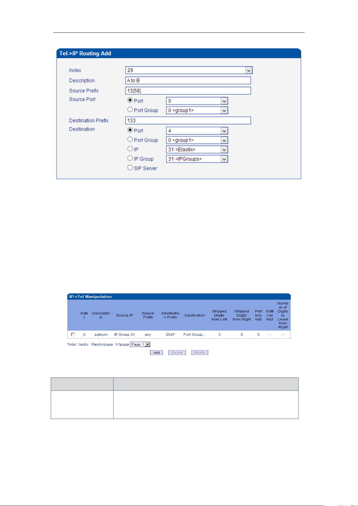
Add mobile to mobile route,its mainly used for saving the cost between two carriers.It
indecates that calls coming from Port 0 will match the prefix 13[58], ”13[58]” include prefix
135 and 138, caller number can’t match prefix 135 and 138 will reject by gateway.
Meanwhile sending the calls to Port Group 31<Unicom> if called number match with
prefix 133.
4.8 Manipulaton Configuration
4.8.1 IP->Tel Destination Numbers
Figure 4-8-1 IP->Tel destination numbers manipulation
Table 4-8-1 Description of IP->Tel destination numbers manipulation
_______________________________________________________________________________
Shenzhen Dinstar Technologies Co., Ltd.
40
Page 42

DWG2000E/F/G GSM/CDMA VoIP Gateway User Manual
Index
It uniquely identifies a route. Its value is assigned globally, ranging
from 0 to 31.The route preferentially match the rules which the
value of index is smaller
Description
It describes the rule for the ease of identification. Its value is
character string
Source IP
It specifies the source IP which will send the calls to gateway
Any: any IP address
IP: specific an IP address
IP Group: specific an IP group
SIP Server
Source Prefix
All the caller number must match the source prefix. It specifies the
source prefix allow to send call out
Any: include anonymous, 0xxxx, 1[2-9]xxxx etc.
0xxxx: consist of some digits such as 015,08,09
1[3-8]6:consist of some prefix, include 136,146,156,166,176, 186
Destination Prefix
All the called number must match the destination prefix, the call
prefix indicates the connected number
Any: include anonymous, 0xxxx, 1[2-9]xxxx etc.
0xxxx: consist of some digits such as 015,08,09
1[3-8]6:consist of some prefix, include 136,146,156,166,176, 186
Destination
Its specifies destination Port or Port Group
Stripped Digits from
Left
It specifies the length of the digits to be deleted from left
Stripped Digits from
Right
It specifies the length of the digits to be deleted from right
Prefix to Add
Add the new digits in front of the original number
Suffix to Add
Add the new digits at the end of the original number
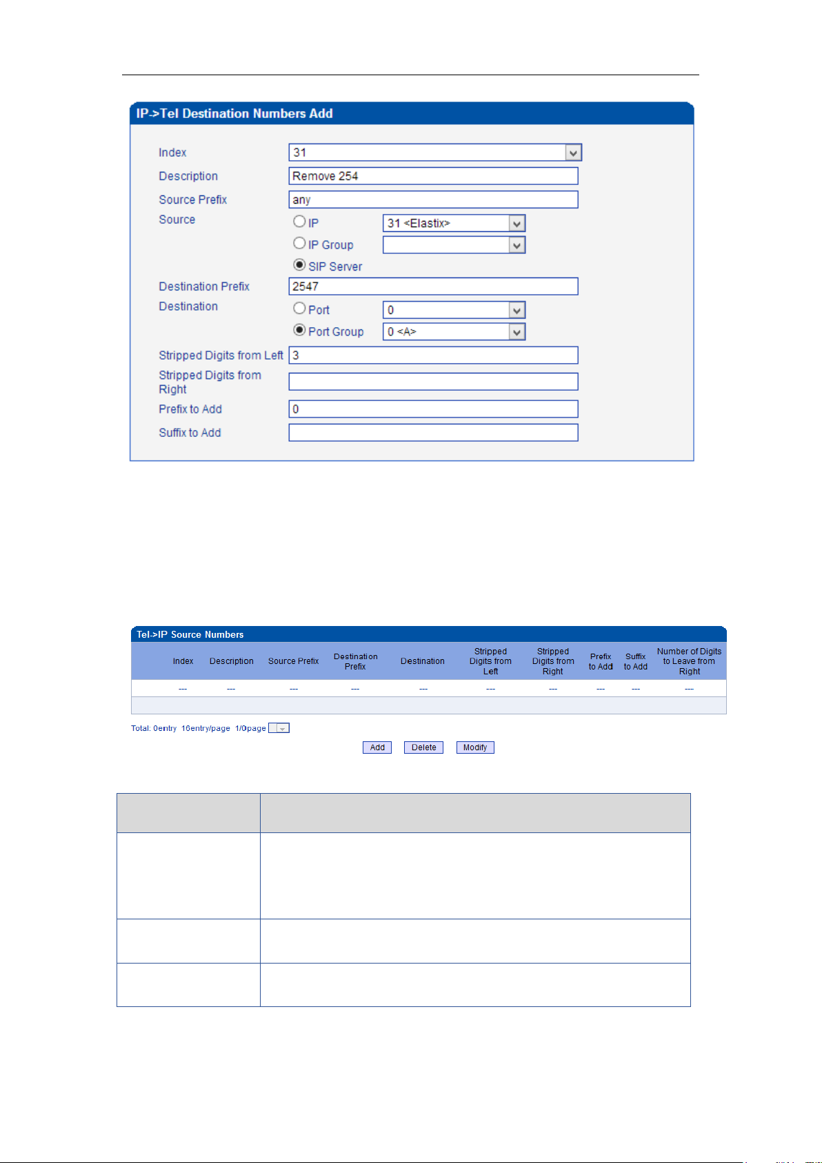
Add an IP->Tel Manipulation, to change the called number from 2547888888 to 07888888
Figure 4-8-2 IP->Tel destination numbers manipulation
_______________________________________________________________________________
Shenzhen Dinstar Technologies Co., Ltd.
41
Page 43
DWG2000E/F/G GSM/CDMA VoIP Gateway User Manual
Parameters
Description
Tel->IP Source
numbers
manipulation
It is an optional configuration item, and is used to add IP->Tel
number change data. The IP->Tel Manipulation defined the rules of
add, and deletion of called numbers, which are referenced by
IP->Tel routing.
Index
It uniquely identifies a route. Its value is assigned globally, ranging
from 0 to 31.
Description
It describes the rule for the ease of identification. Its value is
character string
It indicates that calls coming from IP Group will match the prefix ”any”, and the called
nubmer which match with the prefix ”2547” will delete 3 digits in front of it and replace it by
digit ”0”.
4.8.2 Tel->IP Source Numbers
Figure 4-8-3 Tel->IP destination numbers manipulation
Table 4-8-2 Description of Tel->IP destination numbers manipulation
_______________________________________________________________________________
Shenzhen Dinstar Technologies Co., Ltd.
42
Page 44

DWG2000E/F/G GSM/CDMA VoIP Gateway User Manual
Source Prefix
All the caller number must match the source prefix. It specifies the
source prefix allow to send call out
Any: include anonymous, 0xxxx, 1[2-9]xxxx etc.
0xxxx: consist of some digits such as 015,08,09
1[3-8]6:consist of some prefix, include 136,146,156,166,176, 186
Destination Prefix
All the called number must match the destination prefix, the call
prefix indicates the connected number
Any: include anonymous, 0xxxx, 1[2-9] xxxx etc.
0xxxx: consist of some digits such as 015,08,09
1[3-8]6:consist of some prefix, include 136,146,156,166,176, 186
Destination
Its specifies destinations:
Port
Port Group
IPs
IP Group
SIP Server
Stripped Digits from
Left
It specifies the length of the digits to be deleted from left
Stripped Digits from
Right
It specifies the length of the digits to be deleted from right
Prefix to Add
Add the new digits in front of the original number
Suffix to Add
Add the new digits at the end of the original number
Number of Digits to
Leave from Right
It specifies the number of Digits to Leave from Right
Example
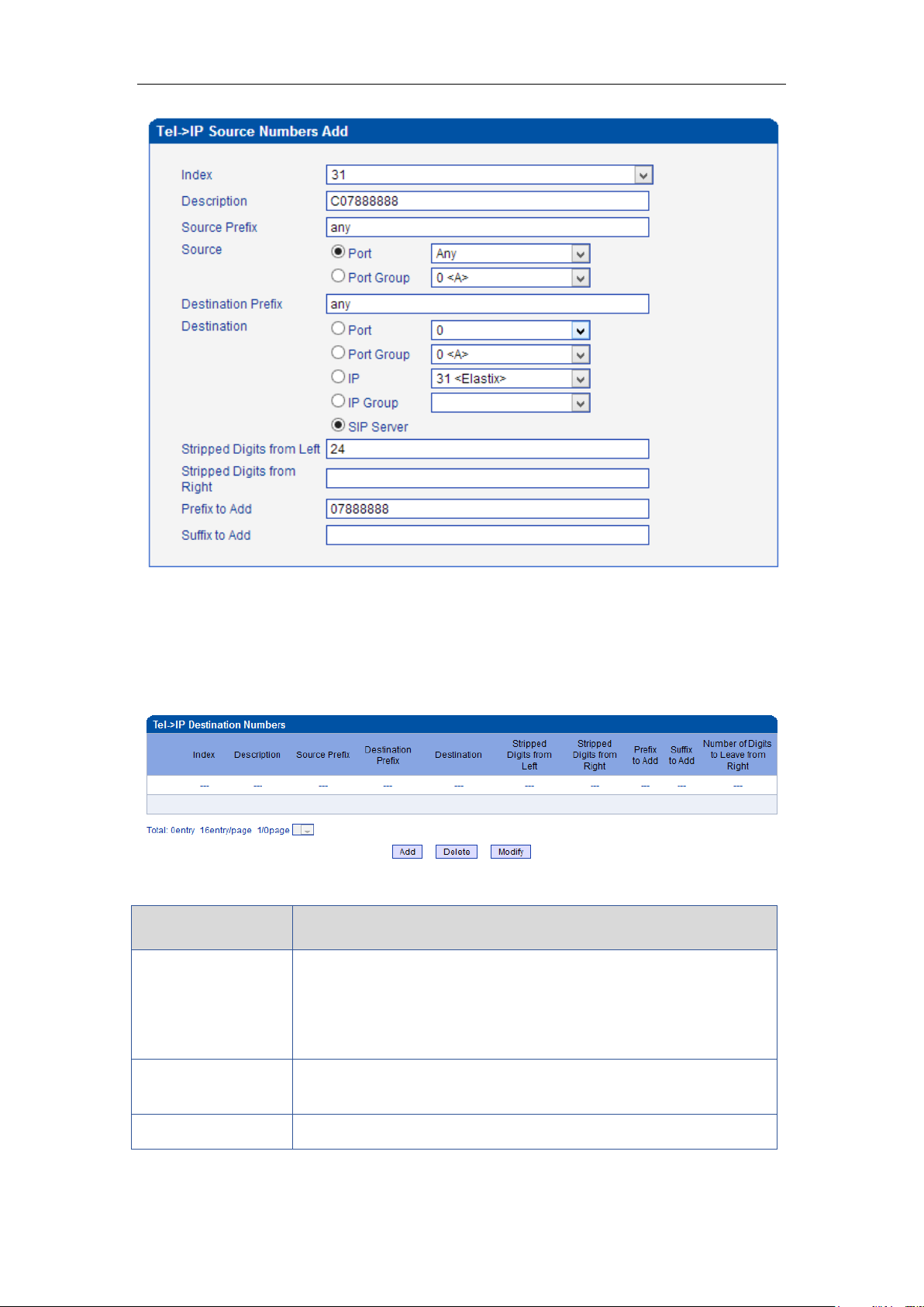
Add a Tel->IP Manipulation, to change the caller number to 07888888
Figure 4-8-4 Tel ->IP destination numbers source manipulation add
_______________________________________________________________________________
Shenzhen Dinstar Technologies Co., Ltd.
43
Page 45
DWG2000E/F/G GSM/CDMA VoIP Gateway User Manual
Parameters
Description
Tel->IP destination
numbers
manipulation
It is an optional configuration item which used to add Tel-> IP
destination number manipulation rules. The Tel-IP Manipulation
defined the rules of add, and deletion of called numbers, which are
referenced by Tel->IP routing.
Index
It uniquely identifies a route. Its value is assigned globally, ranging
from 0 to 31.
Description
It describes the route for the ease of identification. Its value is
It indicates that all incoming calls which matched with source & destination prefix ”any”, to
delete original caller number and replace by 0788888.
4.8.3 Tel->IP Destination Numbers
Figure 4-8-5 Tel->IP destination numbers manipulation
Table 4-8-3 Description of Tel->IP destination numbers manipulation
_______________________________________________________________________________
Shenzhen Dinstar Technologies Co., Ltd.
44
Page 46

DWG2000E/F/G GSM/CDMA VoIP Gateway User Manual
character string
Source Prefix
All the caller number must match the source prefix. It specifies the
source prefix allow to send call out
Any: include anonymous, 0xxxx, 1[2-9] xxxx etc.
0xxxx: consist of some digits such as 015,08,09
1[3-8]6:consist of some prefix, include 136,146,156,166,176, 186
Destination Prefix
All the called number must match the destination prefix, the call
prefix indicates the connected number
Any: include anonymous, 0xxxx, 1[2-9] xxxx etc.
0xxxx: consist of some digits such as 015,08,09
1[3-8]6:consist of some prefix, include 136,146,156,166,176, 186
Destination
Its specifies destinations:
Port
Port Group
IPs
IP Group
SIP Server
Stripped Digits from
Left
It specifies the length of the digits to be deleted from left
Stripped Digits from
Right
It specifies the length of the digits to be deleted from right
Prefix to Add
Add the new digits in front of the original number
Suffix to Add
Add the new digits at the end of the original number
Number of Digits to
Leave from Right
It specifies the number of Digits to Leave from Right
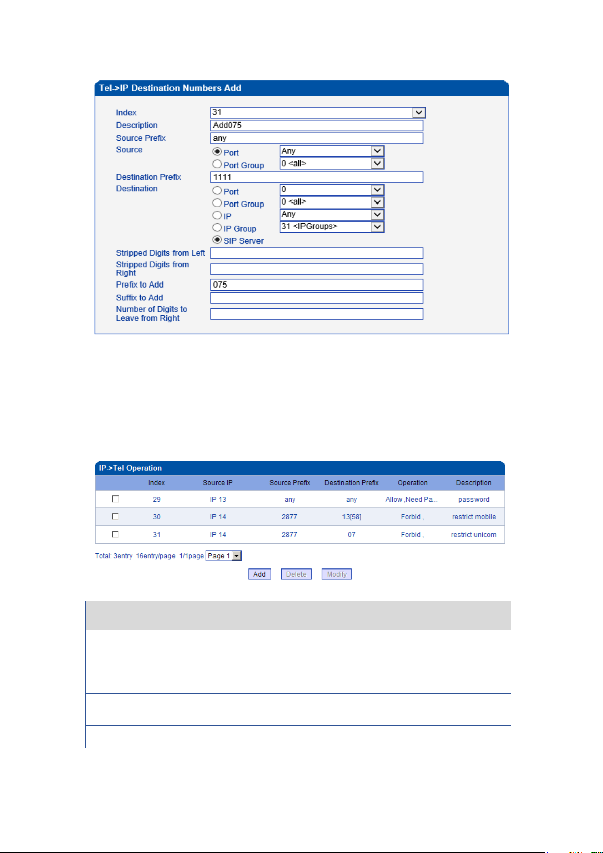
Example
Add a Tel->IP Manipulation rule, to change the called number from 1111 to 0751111
Figure 4-8-6 Tel->IP destination numbers manipulation
_______________________________________________________________________________
Shenzhen Dinstar Technologies Co., Ltd.
45
Page 47
DWG2000E/F/G GSM/CDMA VoIP Gateway User Manual
Parameters
Description
IP->Tel Operation
It is an optional configuration item. Operation configuration
essentially involves allow, barring some IP and IP Group send calls to
certain numbers. It includes: forbid call, call allowance, auto call, and
password authentication.
Index
It uniquely identifies a route. Its value is assigned globally, ranging
from 0 to 31.
Source IP
It specifies the source IP/SIP server which will send the calls to
It indicates that calls incoming call from mobile will match the prefix ”any”, and the called
nubmer which match with the prefix ”1111” will be added 075 in front of called number.
4.9 Operation
4.9.1 IP->Tel Operation
Figure 4-9-1 IP->Tel Operation
Table 4-9-1 Description of IP->Tel Operation
_______________________________________________________________________________
Shenzhen Dinstar Technologies Co., Ltd.
46
Page 48
DWG2000E/F/G GSM/CDMA VoIP Gateway User Manual
gateway
Any: any IP address
IP: specific an IP address
IP Group: specific an IP group
Source Prefix
All the caller number must match the source prefix. It specifies the
source prefix allow to send call out
Any: include anonymous, 0xxxx, 1[2-9]xxxx etc.
0xxxx: consist of some digits such as 015,08,09
1[3-8]6:consist of some prefix, include 136,146,156,166,176, 186
Destination Prefix
All the called number must match the destination prefix, the call prefix
indicates the connected number
Any: include anonymous, 0xxxx, 1[2-9]xxxx etc.
0xxxx: consist of some digits such as 015,08,09
1[3-8]6:consist of some prefix, include 136,146,156,166,176, 186
Operation
Its specifies number analysis rule
Forbid call
Allow call
Auto call
Password authenticate
Description
It describes the route for the ease of identification. Its value is
character string
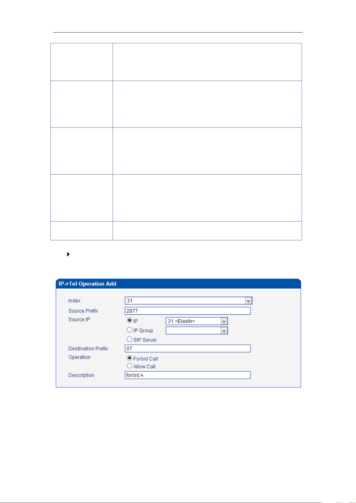
Example: IP-Tel Operation
Index 31: barring the certain calling number from IP 14<elastix>
Figure 4-9-2 IP->Tel Operation
It indicates that calling party from IP 14<elastix> matched prefix 2877, and also called
party matched prefix 07 are not allowed call out. The calls match this rule will be
rejected by gateway.
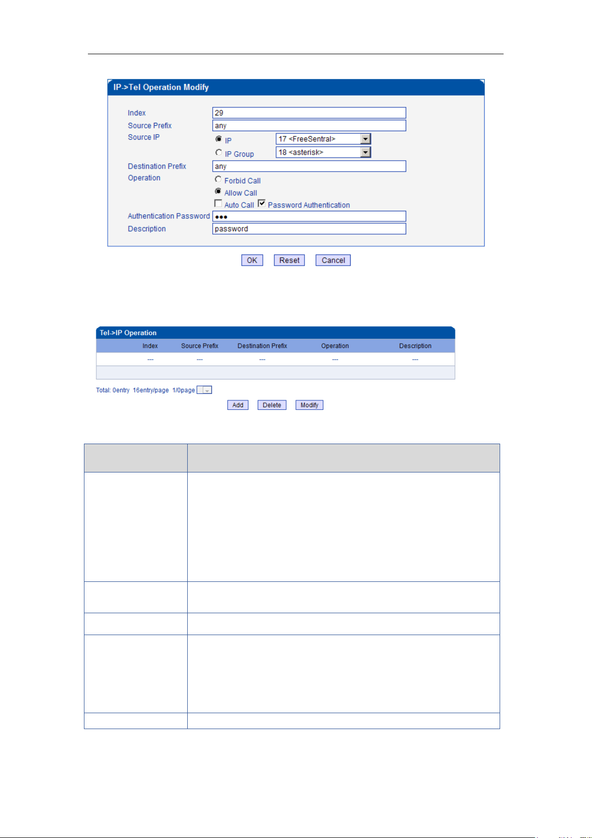
Index 29: define a rule for IP 17<FreeSentral> that all the calls must go with valid
password authentication.
Figure 4-9-3 IP->Tel Operation
_______________________________________________________________________________
Shenzhen Dinstar Technologies Co., Ltd.
47
Page 49
DWG2000E/F/G GSM/CDMA VoIP Gateway User Manual
Parameters
Description
Tel->IP Operation
It is an optional configuration item. To enable following features in
this menu:
Forbid Call
Call Back
Auto Call
Allow Call
Password Authentication
Index
It uniquely identifies a rule. Its value is assigned globally, ranging
from 0 to 31.
Source Port
It specifies the source port which come from mobile
Source Prefix
All the caller number must match the source prefix. It specifies the
source prefix allow to send call out
Any: include anonymous, 0xxxx, 1[2-9]xxxx etc.
0xxxx: consist of some digits such as 015,08,09
1[3-8]6:consist of some prefix, include 136,146,156,166,176, 186
Destination Prefix
All the called number must match the destination prefix, the call
4.9.2 Tel->IP Operation
Figure 4-9-4 Tel->IP Operation
Table 4-9-2 Description of Tel->IP Operation
_______________________________________________________________________________
Shenzhen Dinstar Technologies Co., Ltd.
48
Page 50
DWG2000E/F/G GSM/CDMA VoIP Gateway User Manual
prefix indicates the connected number
Any: include anonymous, 0xxxx, 1[2-9]xxxx etc.
0xxxx: consist of some digits such as 015,08,09
1[3-8]6:consist of some prefix, include 136,146,156,166,176, 186
Operation
Its specifies number analysis rule
Forbid call
Call Back
Allow call
Auto call
Password authenticate
Description
It describes the route for the ease of identification. Its value is
character string
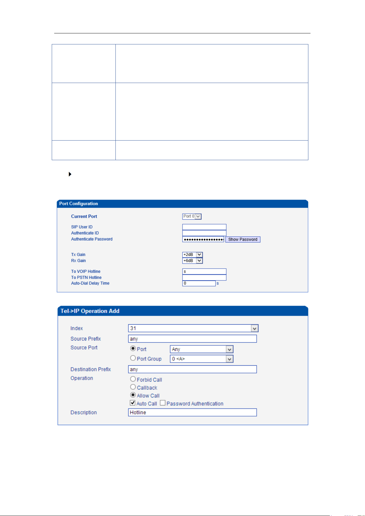
How to route incoming call to DID or IVR automatically?
Step1: System Configuration-> Port Configuration to configure VoIP hotline number,
this hotline number can be DIDs, access code and extension etc.
Step2: Operation-> Tel->IP Operation to add a new rule:
_______________________________________________________________________________
Shenzhen Dinstar Technologies Co., Ltd.
49
Page 51
DWG2000E/F/G GSM/CDMA VoIP Gateway User Manual
Parameters
Description
IP Trunk
Add remote IP of Softswitch, SIP server which will send call traffics to
gateway.
Index
It uniquely identifies a trunk. Its value is assigned globally, ranging
from 0 to 31.
Description
It describes the trunk for the ease of identification. Its value is
character string
4.10 Port Group Configuration
4.10.1 Port Group
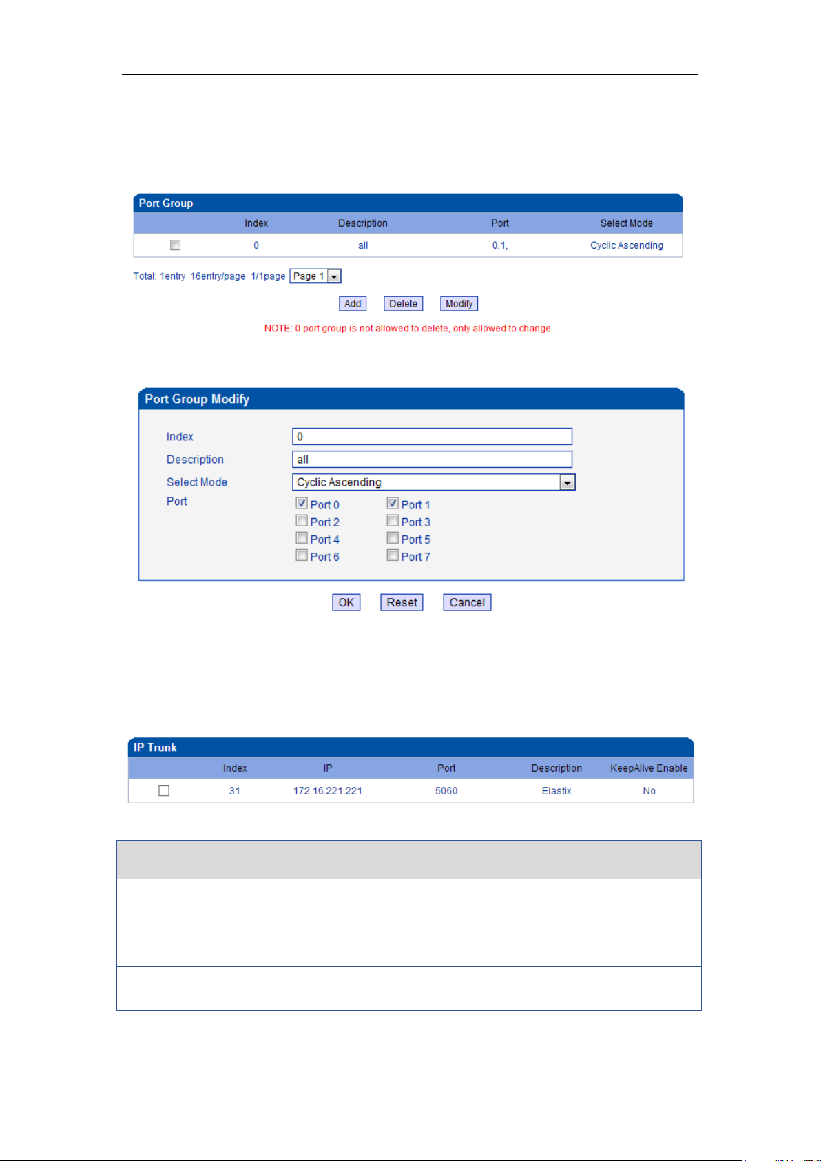
Figure 4-10-1 Port Group
Figure 4-10-2 Port Group Modify
4.11 IP Trunk Configuration
4.11.1 IP Trunk
Table 4-11-1 Description of IP Trunk
Figure 4-11-1 IP Trunk
_______________________________________________________________________________
Shenzhen Dinstar Technologies Co., Ltd.
50
Page 52
DWG2000E/F/G GSM/CDMA VoIP Gateway User Manual
IP
It is an interworking parameter between the remote Softswitch and the
SIP server. It specifies the IP address of the peer equipment.
Port
It is an interworking parameter between the remote Softswitch and the
SIP server. It specifies the SIP port number of the peer equipment
Keep alive
Send OPTION to Softswitch/IPPBX to detect health status
Parameters
Description
IP Trunk Group
This configuration is optional, and is used to add the IP that have the
same attributes to an IP group. The IP group will referenced by
IP->Tel routing and number manipulation.
Index
It uniquely identifies a route. Its value is assigned globally, ranging
from 0 to 31.
Description
It describes the route for the ease of identification. Its value is
character string
IP
It specifies the IP will add to IP group
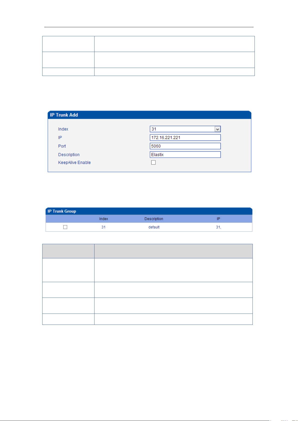
Example
To add a remote IP of Softswitch, IP trunk index is 31, SIP port number “5060”
Figure 4-11-2 IP Trunk Modify
4.11.2 IP Trunk Group
Figure 4-11-3 IP Trunk Group
Table 4-11-2 Description of IP Trunk Group
Example
To add an IP group, set IP “10, 14, 17” to IP group 18
Figure 4-11-4 IP Trunk group modify
_______________________________________________________________________________
Shenzhen Dinstar Technologies Co., Ltd.
51
Page 53
DWG2000E/F/G GSM/CDMA VoIP Gateway User Manual
4.12 System Configuration
4.12.1 Service Parameter
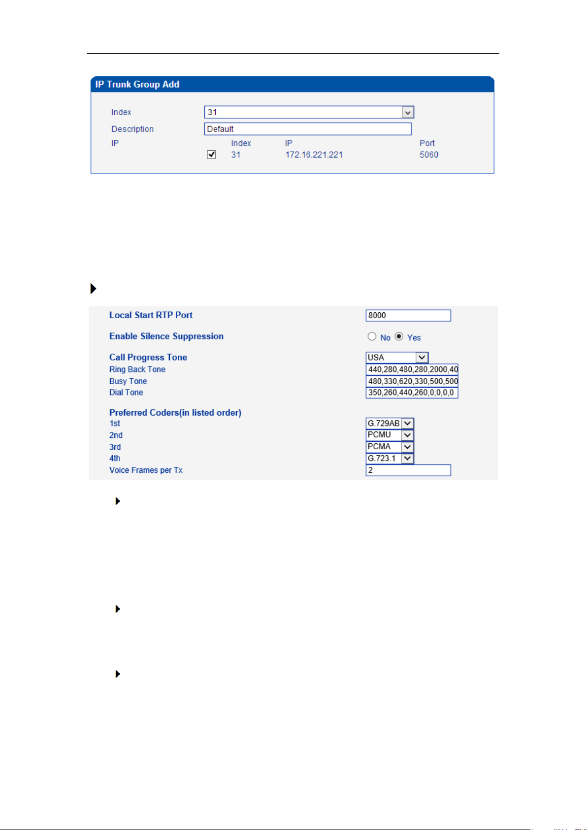
Service Configuration is used for configuring voice calls and some small businesses, such as
Call Progress Tone, codec, silence suppression, * service, the second dial and so on.
To configure voice Processing Parameters
Local Start RTP Port
Means the initial port when RTP voice stream transmit in the IP network, in general,
using the factory default values. When there are several DINSTAR units are deployed
and they are in the same network or behind the same NAT, user can try to change it
to avoid NAT traversal issue;
Enable Silence Suppression
Enable the "silence suppression" almost no impact on call quality, and can save
about half of the bandwidth;
Call Progress Tone
Each country has its different call progress tone required standards, such as busy
tone, ring back tones and ring tone standards, users can select the area standard
_______________________________________________________________________________
Shenzhen Dinstar Technologies Co., Ltd.
52
Page 54
DWG2000E/F/G GSM/CDMA VoIP Gateway User Manual
from here
USA Standard:
Ringback Tone: 440,280,480,280,2000,4000,0,0 frequency: 440/480Hz on:2000ms
off:4000ms
Busy Tone: 480, 330, 620, 330, 500, 500, 0, 0 frequency: 480/620Hz, on: 500ms off:
500ms
Preferred Coders
Means the code format when Voice transfer on IP network, support PCMA, PCMU,
G.723.1 andG.729AB.
To configure dialing mode parameters
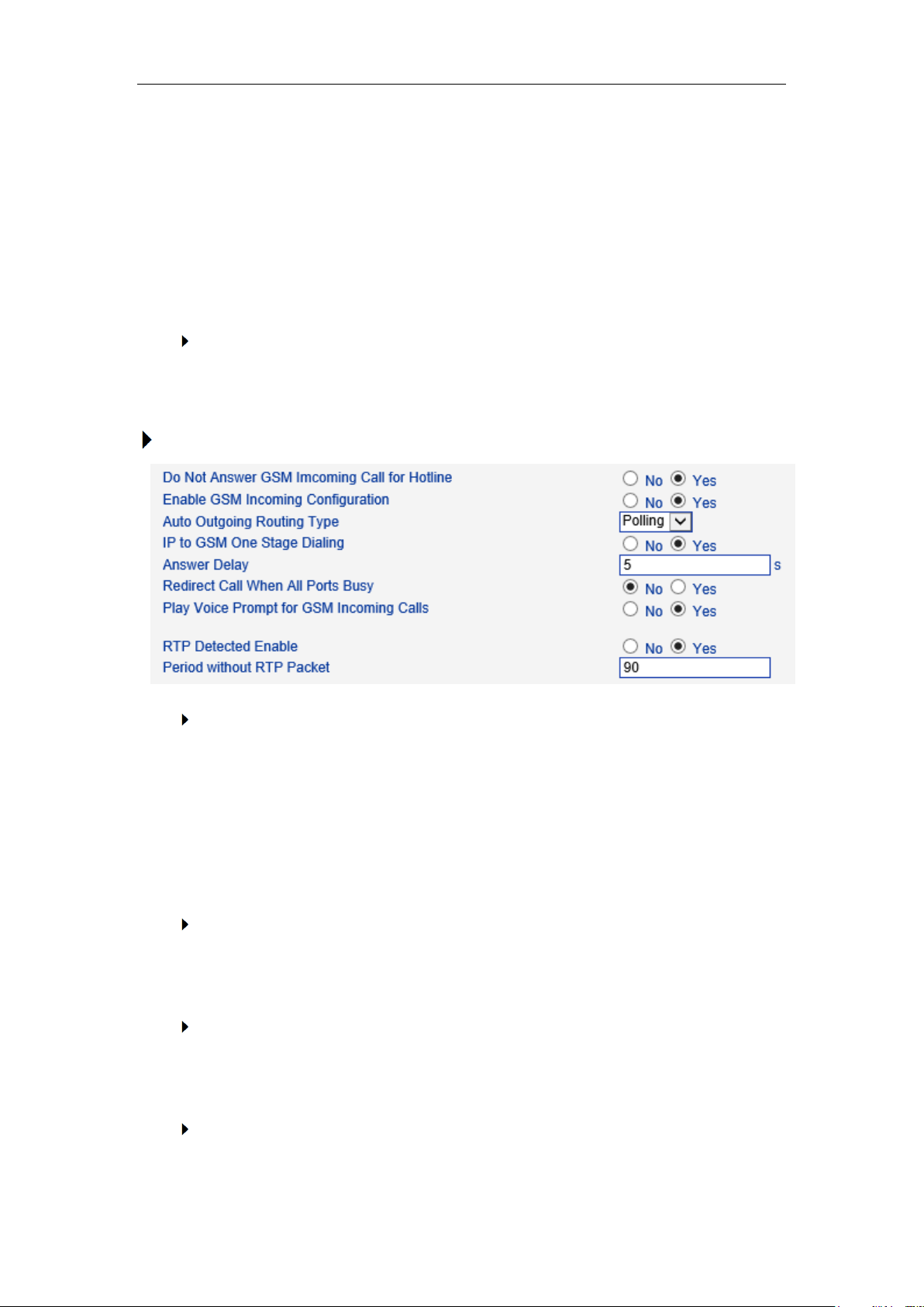
Do Not Answer GSM Incoming Call for Hotline
When the gateway get incoming call from mobile network, the module will answer the
call then start to DTMF or route to destination hotline number. While this option
enabled, the module won’t answer the call but routing to destination hotline number
till it getting answer.
Notes: Refer to Port Parameter page for Hotline configuration.
Enable PSTN Incoming Configuration
Means when call from mobile side, you can dial the feature codes (Chapter 3 Basic
Operation) to configure IP address and so on
Enable Auto Outgoing Routing
Means when call out, whether by ordinal or polling pick to Select a Channel, this
feature are generally used when use the same SIP User ID to register.
IP to PSTN One Stage Dialing
_______________________________________________________________________________
Shenzhen Dinstar Technologies Co., Ltd.
53
Page 55
DWG2000E/F/G GSM/CDMA VoIP Gateway User Manual
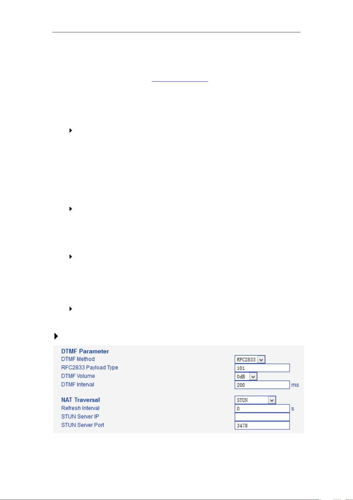
The GSM/CDMA gateway support two dialing mode, one stage and two stage
dialing. One stage dialing will obtain called number from INVITE message body,
either Request line or To <SIP:[email protected]> field. Then deliver called number
to GSM/CDMA directly.
But for two stage dialing, the SIP server must be dial the SIP channel account and
then to generate DTMF to mobile network.
Answer Delay
In most instances, Most of CDMA operators don't offer answer signal. The gateway
doesn’t response SIP 200 OK to SIP server in case of missing answer signal from
CDMA network. Answer delay is to fix this issue and generate SIP 200 OK to SIP
server after answer delay timeout. Default value is 5 seconds. Moreover, it is
available for CDMA gateway only.
Redirect Call when All Port Busy
When the gateway is running heavy traffic and not possible to call out, the call will
redirect to specific destination route as configuration.
IP and Port: destination gateway or IPPBX to be redirect
Play Voice Prompt for PSTN Incoming Calls
Default setting is Yes. when the gateway receive incoming from mobile, it will play
default/customized voice prompt to caller party. Default voice prompt is "Please dial
the extension "; if set to No, the device will play dial tone instead of voice prompt.
RTP Detect
This option is to disconnect call when there is no RTP received. Default value is 90s
Configure DTMF and NAT Traversal
_______________________________________________________________________________
Shenzhen Dinstar Technologies Co., Ltd.
54
Page 56
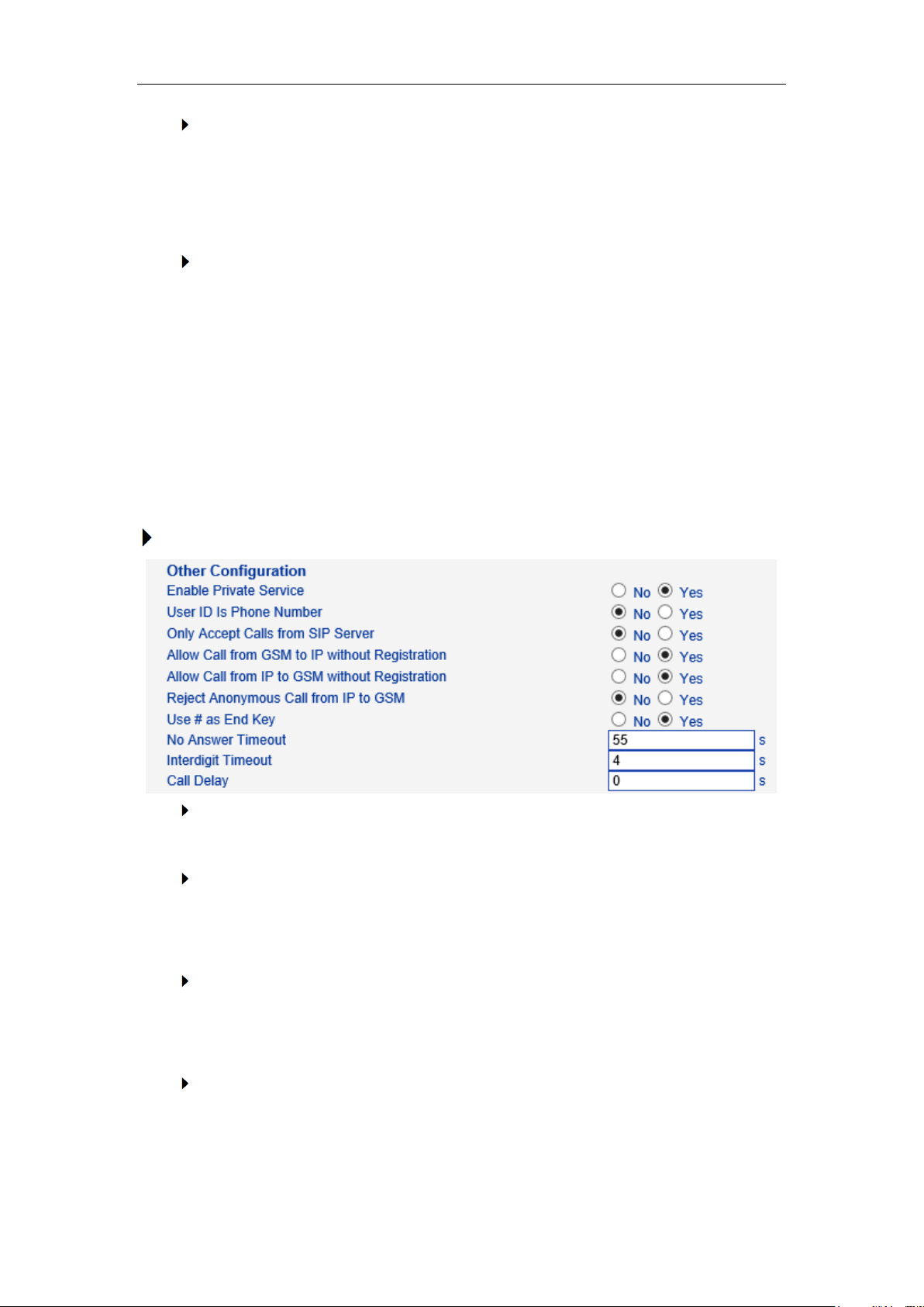
DWG2000E/F/G GSM/CDMA VoIP Gateway User Manual
DTMF
DWG2001/DWG2004/DWG2000B-8G support RFC2833 and SIGNAL two ways.
DTMF INTERVAL range is 50 ~ 800ms, DTMF VOLUME can use the default
Configuration
Nat Traversal
Include Static NAT, Dynamic NAT and STUN
STUN (Simple Traversal of UDP over NATs) is a network protocol. It is allowed to
stay behind the NAT (or multiple NAT) client part to identify their clients’ public
address, found himself after what Type of NAT and NAT for a particular Channel is
bound to a local Internet terminal Channel. This information is used for two host to
set up UDP communication behind the same NAT router. The agreement defined by
the RFC 3489
Other configuration
Enable Private Service
To enable local services like *158# etc.
User ID Is Phone Number
Default is No. user=phone will be added in SIP message body when this option
enabled.
Only Accept Calls from SIP Server
Default is No. All calls will be rejected except calls from SIP server. IP Trunk will not
work when this option enabled.
Allow Call from PSTN to IP without Registration
Refer to "SIP Configuration" -> "Is register”. If "Is register" setting is no, this option
_______________________________________________________________________________
Shenzhen Dinstar Technologies Co., Ltd.
55
Page 57
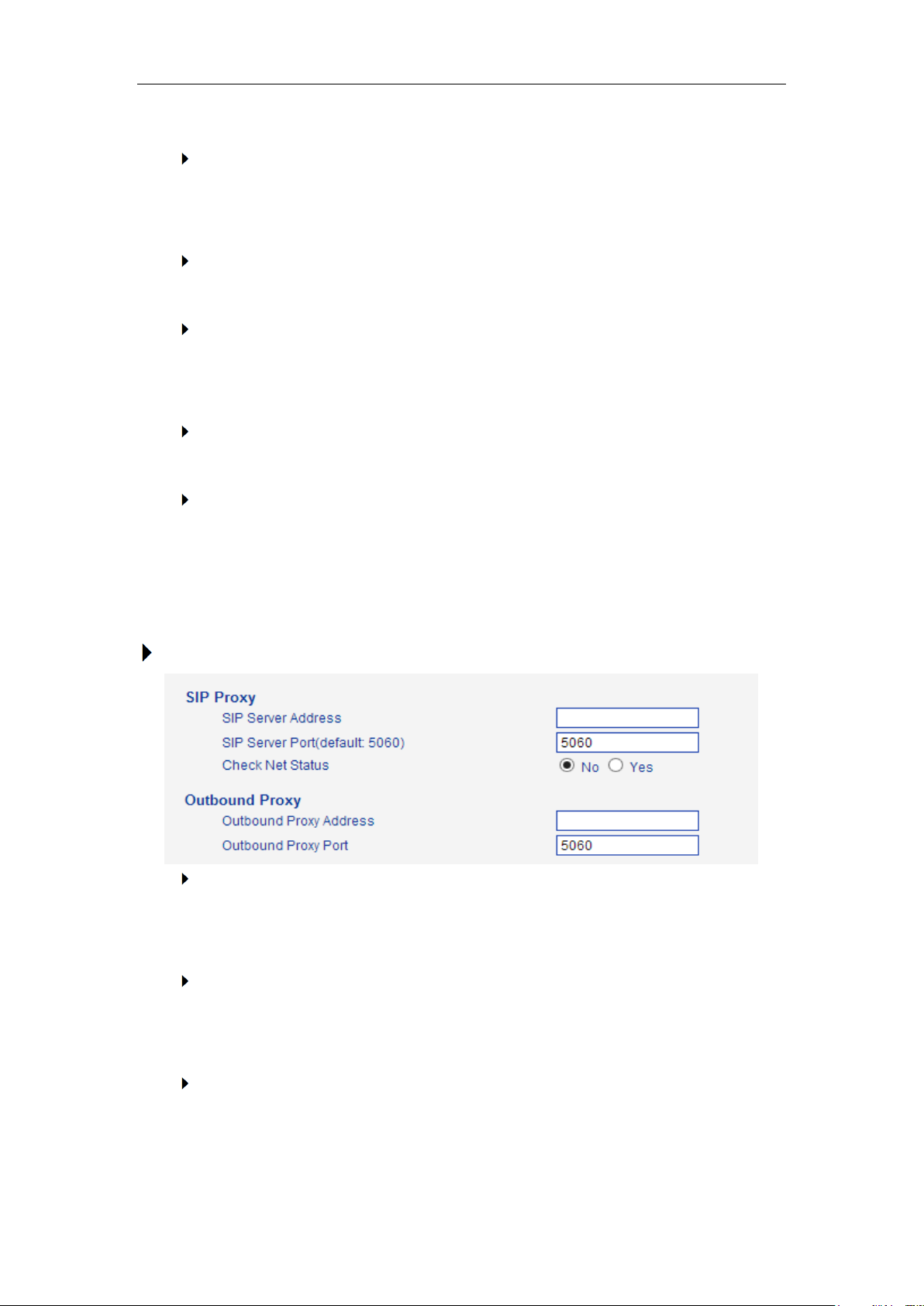
DWG2000E/F/G GSM/CDMA VoIP Gateway User Manual
need set Yes, to avoid that the devices can not call in
Allow call from IP to PSTN without Registration
Refer to "SIP Configuration" -> "Is register”. If "Is register" setting is no, this option
need set Yes ,to avoid that the devices can not call out
Reject Anonymous call from IP to PSTN
The incoming anonymous calls will be rejected
Use # as End Key
In General, SIP phones are based on # as the end, if this option is set to No, the
dial-up will end expires dial-up time
Interdigit Timeout
Bit of between the dialing time ,over the time will be seem as end of dia
Call Delay
Default value is 0s.
4.12.2 SIP Parameter
This section is describes how to configure SIP server and SIP parameters.
Configure SIP server and Outbound Proxy server
SIP Server Address and Port
Used for configure SIP server address and port, the address can be IP Address, also
can be a domain name which can be resolved by DNS server
Check NET Status
Default is No. if it set to Yes, the gateway will send SIP OPTION periodic to check
health status between gateway and SIP server.
Outbound Proxy
Outbound proxy, it mainly used in firewall / NAT environment. That make the
_______________________________________________________________________________
Shenzhen Dinstar Technologies Co., Ltd.
56
Page 58
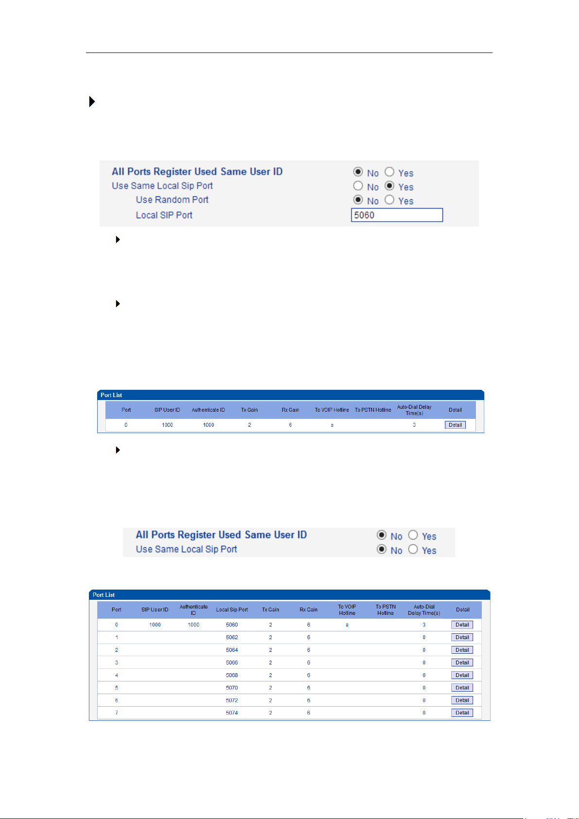
DWG2000E/F/G GSM/CDMA VoIP Gateway User Manual
signaling and media streams are able to penetrate the firewall.
Local SIP Port Configuration
In order to work different application scenarios, the gateway provides flexible
configuration with local SIP port.
Random
The gateway will generates SIP port after each reboot by random. It is commonly
used while 5060 is blocked or conflict with other devices.
Use the same SIP port
t is mostly used to SIP trunk interworking with SIP server so that the gateway able to
I
deal with high performance concurrent calls.
Use the same local SIP port and SIP User ID
Use the separate SIP port
Each channel has separate SIP port so that they could be handle SIP call
separately.
After Use Same Local SIP Port set to No
The Local SIP port will be changed on Port Parameter page.
_______________________________________________________________________________
Shenzhen Dinstar Technologies Co., Ltd.
57
Page 59
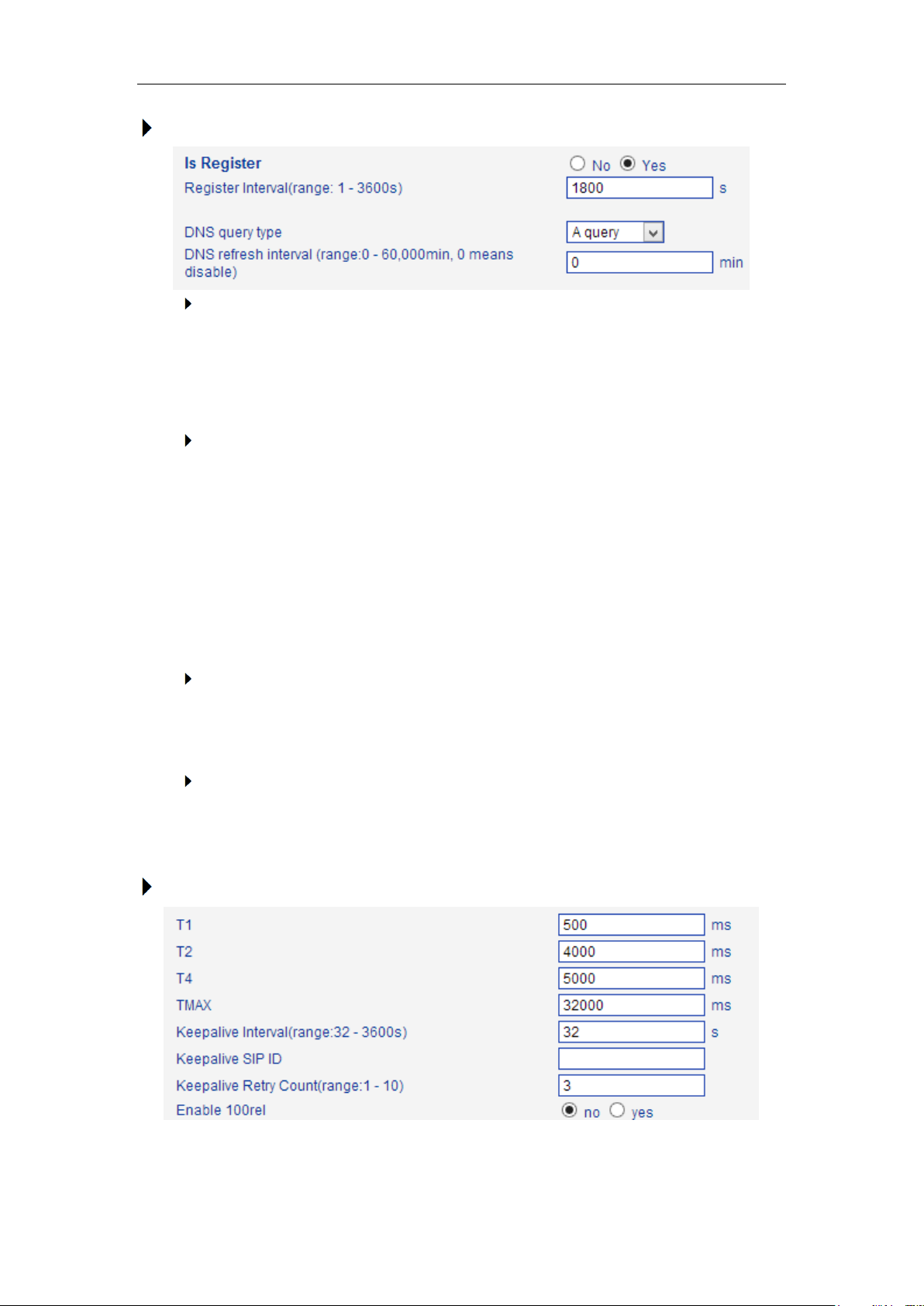
DWG2000E/F/G GSM/CDMA VoIP Gateway User Manual
Register Interval and DNS SRV
Is Register
Default set yes, if you want the device can make a call without register, set No, Also
enable the "Allow Call from IP to PSTN without Registration" and "Allow Call from
PSTN to IP without Registration" function
Register Interval
This field specifies the value that the gateway will send in the Expires header of the
REGISTER message. Its value range from 1-3600s. But in fact, the gateway will get
200OK response from SIP server after REGISTER request, and an Expires header
will be included in 200 OK message body. This value in the 200OK determines the
time, in seconds, after which the registration expires. The gateway will refresh the
registration Timer Register Delta seconds before the end of this interval.
DNS query type
The DNS query type defines the type of information that will be requested from DNS
server
DNS refresh interval
The interval of DNS refresh, Range from 0 to 60000 mins, 0 means disable default
value is disable.
Configuring SIP Timers
_______________________________________________________________________________
Shenzhen Dinstar Technologies Co., Ltd.
58
Page 60

DWG2000E/F/G GSM/CDMA VoIP Gateway User Manual
T1
This field specifies the lowest value, in milliseconds, of the retransmission timer for
SIP messages. Default specifies 500.
T2
This field specifies retransmission timer for T1 timeout of SIP message, in
milliseconds. Default specifies 4000.
T4
This field specifies retransmission timer for T2 timeout of SIP message, in
milliseconds. Default specifies 5000.
TMAX
This field specifies maximum timeout value for SIP message. The SIP message will
be dropped after TMAX. Default value is 32000
Keepalive Interval
The gateway can monitor the status of SIP server by sending periodic SIP OPTION
messages. This field specifies transmission timer of OPTION message. Its range
from 10-3600s.
Keepalive SIP ID
This field specifies SIP ID of OPTION. The format would be <[email protected] >,
example:
OPTIONS sip:[email protected]:2080 SIP/2.0
Via: SIP/2.0/UDP 172.16.222.22;branch=z9hG4bK45c4f8d2026d9eed8a0adcd533161efd;
From: <sip:[email protected]:2080>;tag=6d48f0a169d33fe7b032c0fd895084fd
To: <sip:[email protected]:2080>
Call-ID: [email protected]
CSeq: 1804289386 OPTIONS
Contact: <sip:[email protected]>
Max-Forwards: 70
Accept: application/sdp
Content-Length: 0
Keepalive Retry Count
This field specifies re-transmission times for OPTION message. Its value range from
1-10 times.
Configuring Caller ID and 183 Mode
_______________________________________________________________________________
Shenzhen Dinstar Technologies Co., Ltd.
59
Page 61
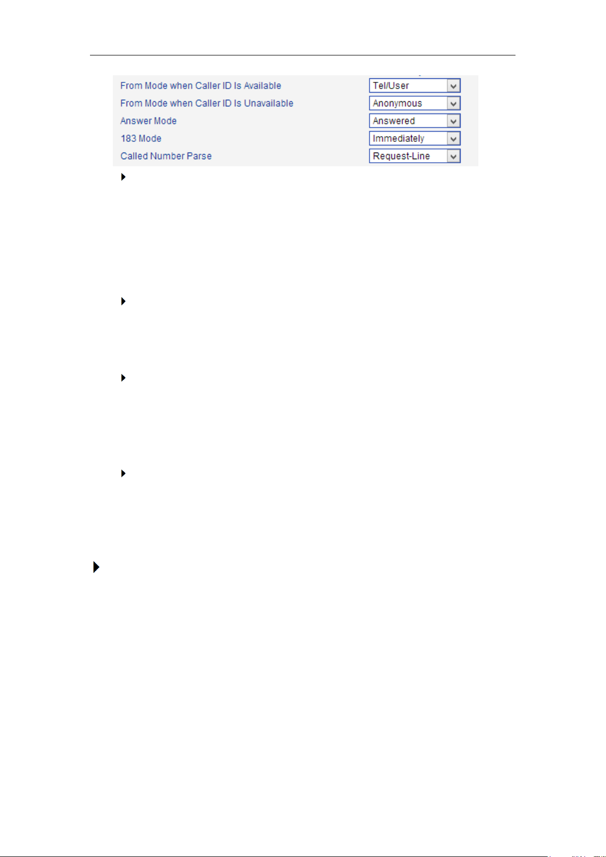
DWG2000E/F/G GSM/CDMA VoIP Gateway User Manual
From Mode when Caller ID Is Available
Used to configure "From" Mode when Caller ID Is Available when call from GSM to
VoIP
Tel/User: From: Caller ID <sip:[email protected]>;tag=51088abb
User/User: From: 3001 <sip:[email protected]>;tag=51088abb
Tel/Tel: From: Caller ID <sip: Caller [email protected]>;tag=51088abb
User/Tel:
From Mode when Caller ID Is Unavailable
Used to configure "From" Mode when Caller ID Is Unavailable
Anonymous : From: <sip: Anonymous @host.com>;tag=51088abb
Username :
From: 3001 <sip: Caller ID @host.com>;tag=51088abb
From: <sip: Username @host.com>;tag=51088abb
Answer Mode
Answered: Gateway will send SIP message "200 OK" to SIP Server after
GSM/CDMA users answered the call.
Alerted: Gateway will send SIP message ‘200 OK’ to SIP Server immediately after
183 Ringing. In this situation, the called party possibly still in ringing status.
183 Mode
Immediately: Gateway will send "183 RING" immediately to SIP Server while it
receive “INVITE". In this situation, the called party possibly still not in ringing status.
Alerted: Gateway will send "183 RING" after received exact ringing signal from
GSM/CDMA network. In this situation, the called party is definely in ringing status.
Session Timer
SIP Session Timers which is an extension of SIP RFC 4028 that allows a periodic
refreshing of a SIP session using the RE-INVITE/UPDATE message. The refreshing
allows both the user agent and proxy to determine if the SIP session is still active. The
SIP Session Timer is a keep alive mechanism for SIP sessions that allow User Agents
(UA) or proxies to determine the status of a session and to release it if it is not active,
even if a BYE has not been received.
_______________________________________________________________________________
Shenzhen Dinstar Technologies Co., Ltd.
60
Page 62
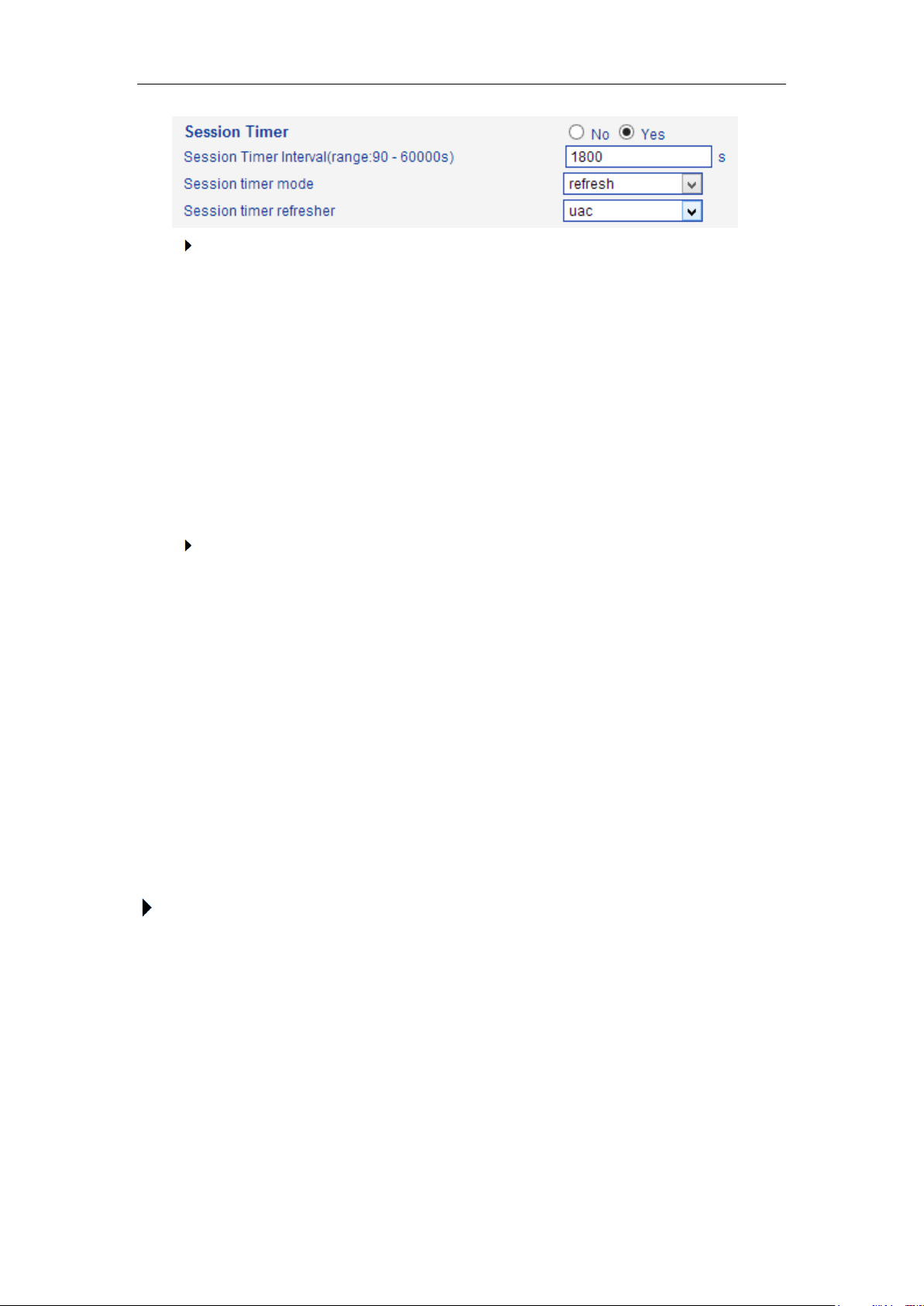
DWG2000E/F/G GSM/CDMA VoIP Gateway User Manual
Session timer Interval
The initial INVITE request establishes the duration of the session and may include a
Session-Expires header and a Min-SE header. These headers indicate the session
timer value required by the user agent (UAC). A receiving user agent server (UAS) or
proxy can lower the session timer value, but not lower than the value of the Min-SE
header. If the session timer duration is lower than the configured minimum, the proxy
or UAS can also send out a 422 response message. If the UAS or proxy finds that the
session timer value is acceptable, it copies the Session-Expires header into the 2xx
class response.
A UAS or proxy can insert a Session-Expires header in the INVITE if the UAC did not
include one. Thus a UAC can receive a Session-Expires header in a response even if
none was present in the request. Its value range from 90-60000s.
Session Timer Refresher
It specifies refresher which including in SIP message body, user agent client (UAC) or
user agent server (UAS).
UPDATE sips:[email protected] SIP/2.0
Via: SIP/2.0 pc33.atlanta.example.com;branch=z9hG4bKnashds12
Route: sips:p1.atlanta.example.com;lr
Supported: timer
Session-Expires: 4000;refresher=uac
Max-Forwards: 70
To: Bob <sips:[email protected]>;tag=9as888nd
From: Alice <sips:[email protected]>;tag=1928301774
Call-ID: a84b4c76e66710
CSeq: 314162 UPDATE
Contact: <sips:[email protected]>
Configuring GSM-SIP Mapping Code
This part specifies response codes between GSM cause reason and SIP response code.
_______________________________________________________________________________
Shenzhen Dinstar Technologies Co., Ltd.
61
Page 63
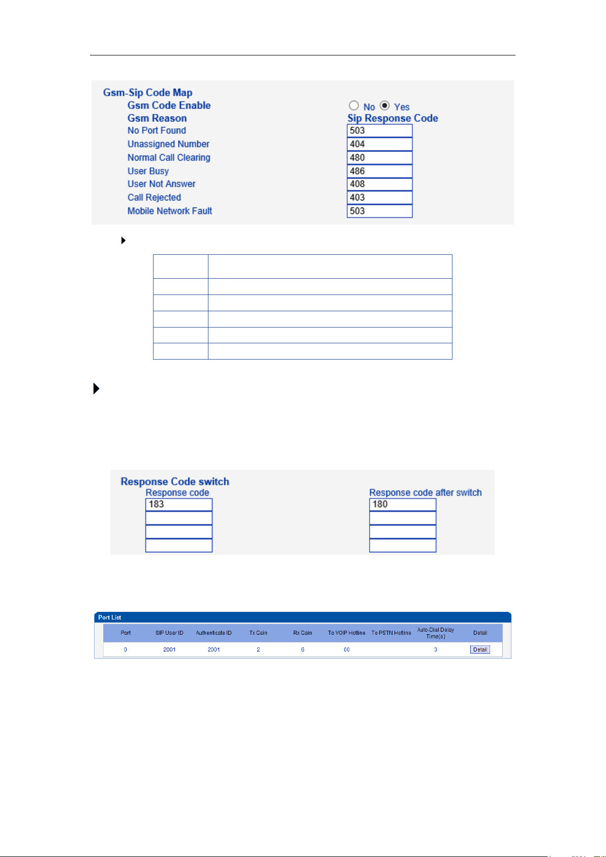
DWG2000E/F/G GSM/CDMA VoIP Gateway User Manual
404
Not Found
408
Request Timeout
403
Forbidden
486
Busy Here
480
Temporarily unavailable Resource unavailable
503
Service Unavailable
SIP Response
Response Code switch
This part specifies response codes of SIP between gateway and SIP server. Refer to table
SIP Response, the SIP server possibly need some specific SIP response from the
gateway. Example, SIP server need SIP response 180 Ringing instead of 183 Ringing,
the configuration should be as below:
4.12.3 Port Parameter
Figure 4-12-3 Port List
Figure 4-12-4 Port Configuration
_______________________________________________________________________________
Shenzhen Dinstar Technologies Co., Ltd.
62
Page 64
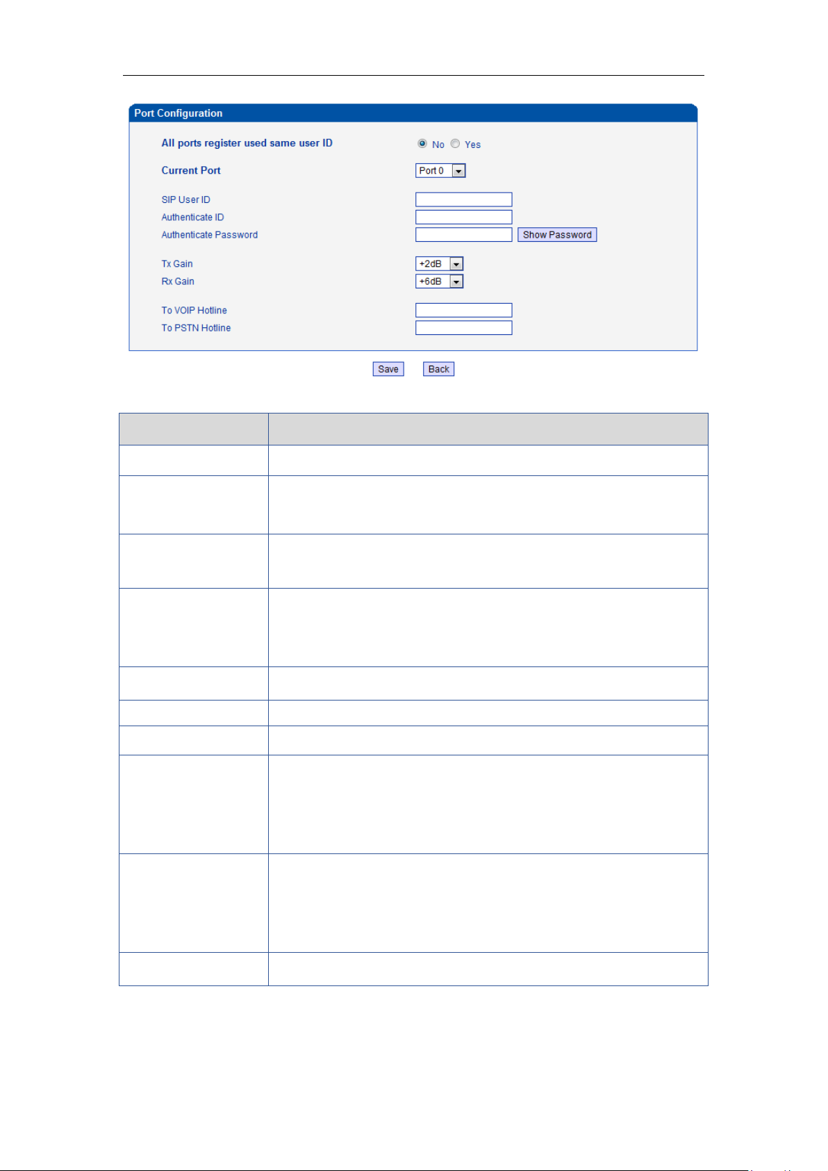
DWG2000E/F/G GSM/CDMA VoIP Gateway User Manual
Parameters
Description
Port Configuration
Used to configure ports’ gain, Auto-Dial, etc.
ALL ports register
used same user ID
The default is no. If set to "yes" ,all the ports will use the same user ID
to register to SIP server
SIP User ID
It is the account used for registration which provide by SIP server,
equipment port's unique identifier
Authenticate ID
The Authentication ID is used for authentication purposes. The SIP
user ID is usually the phone number you received from the service
provider. Often, the Authentication ID is the same as the user ID
Password
Password of SIP User ID which provide by SIP server
Tx Gain
Tx Gain value of chipset. Adjusting it will effect volume on GSM side.
Rx Gain
Rx Gain value of chipset. Adjusting it will effect volume on IP side.
To VoIP Hotline
When mobile / fixed line users make call to this port, gateway will
auto forward to dedicate number. The hotline could be DID / Ring
Group / Extension of SIP server / IP-PBX.
*Note: Please configure Tel->IP Operation if you need this function.
To PSTN Hotline
When VoIP users make calls to this port, gateway will auto forward to
dedicate number. The Hotline number could be mobile / fixed line
number. Leave it blank if you don’t need this function.
*Note: Please configure IP->Tel Operation if you need this function.
Auto-Dial Delay Time
The auto-dial delay time of hotline , the range is 0-10 seconds
Table 4-12-3 Description of Port Configuration
_______________________________________________________________________________
Shenzhen Dinstar Technologies Co., Ltd.
63
Page 65
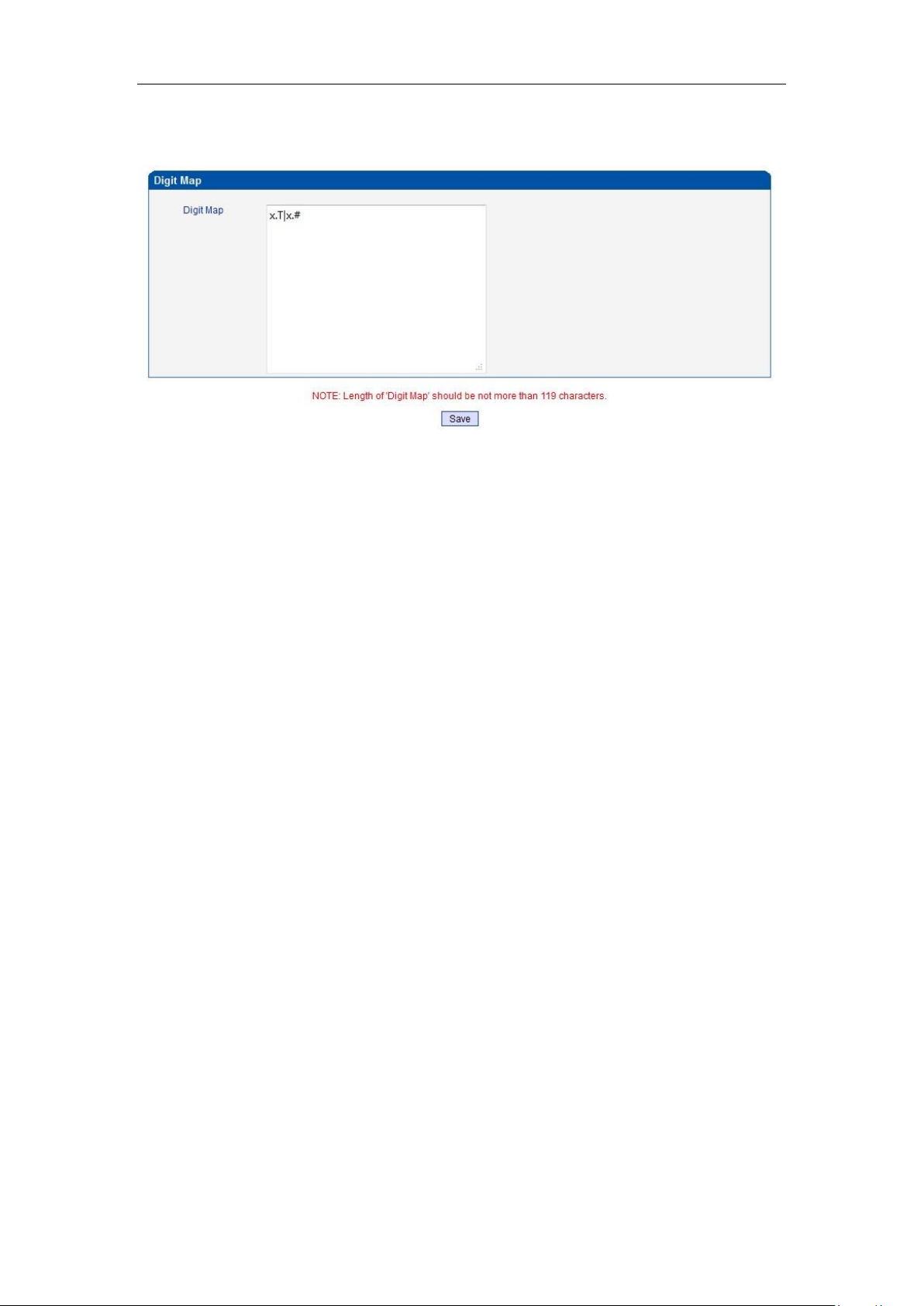
DWG2000E/F/G GSM/CDMA VoIP Gateway User Manual
4.13 Digit Map
Figure 4-13-1 Digit map
Digit Map Syntax:
1. Supported objects
Digit: A digit from "0" to "9".
Timer: The symbol "T" matching a timer expiry.
DTMF: A digit, a timer, or one of the symbols "A", "B", "C", "D", "#", or "*".
2. Range []
One or more DTMF symbols enclosed between square brackets ("[" and "]"), but only one
can be selected.
3. Range ()
One or more expressions enclosed between round brackets ("(" and ")"), but only one can
be selected.
4. Separator
|: Separated expressions or DTMF symbols.
5. Subrange
-: Two digits separated by hyphen ("-") which matches any digit between and including the
two. The subrange construct can only be used inside a range construct, i.e., between "[" and
"]".
6. Wildcard
x: matches any digit ("0" to "9").
7. Modifiers
.: Match 0 or more times.
8. Modifiers
+: Match 1 or more times.
9. Modifiers
?: Match 0 or 1 times.
Example:
Assume we have the following digit maps:
1. xxxxxxx | x11
and a current dial string of "41". Given the input "1" the current dial
_______________________________________________________________________________
Shenzhen Dinstar Technologies Co., Ltd.
64
Page 66
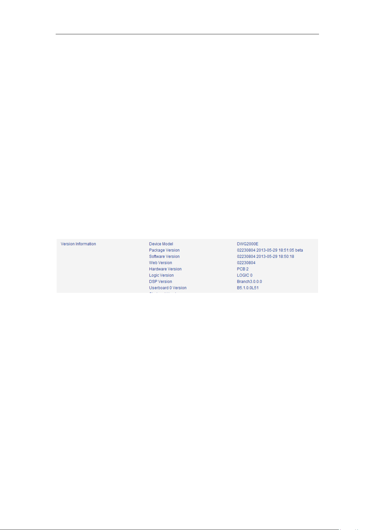
DWG2000E/F/G GSM/CDMA VoIP Gateway User Manual
string becomes "411". We have a partial match with "xxxxxxx", but a
complete match with "x11", and hence we send "411" to the Call Agent.
2. [2-8] xxxxxx | 13xxxxxxxxx
Means that first is "2","3","4","5","6","7" or "8", followed by 6 digits;
or first is 13, followed by 9 digits.
3. (13 | 15 | 18)xxxxxxxxx
Means that first is "13","15" or "18", followed by 8 digits.
4. [1-357-9]xx
Means that first is "1","2","3" or "5" or "7","8","9", followed by 2 digits.
4.14 Tools
4.14.1 Firmware Upload
Firmware upload steps:
Step 1.
Check current running version on gateway, to get firmware version on web page System
Information
Step 2.
Prepare firmware package. The most important is that the package must be match with
existing version. Package version consist of several parts, as below:
01/02-22/23-xx-xx
01/02 is vendor name
22/23 is hardware version, 02.22.xx.xx and 02.23.xx.xx means they had different hardware
version
xx-xx is version number
Step 3.
Upload firmware, select the package from specific folder on the computer and click Upload
button.
_______________________________________________________________________________
Shenzhen Dinstar Technologies Co., Ltd.
65
Page 67
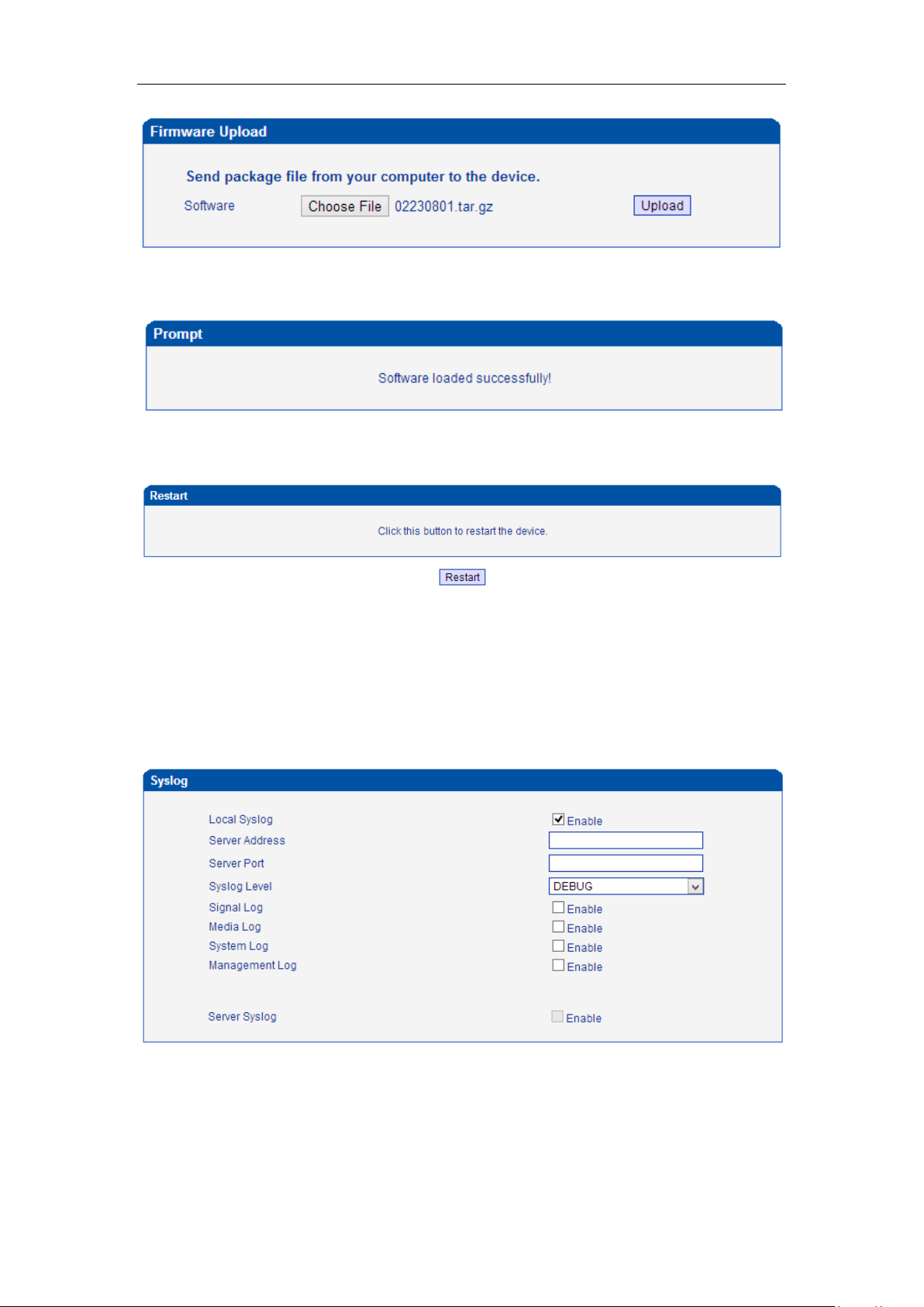
DWG2000E/F/G GSM/CDMA VoIP Gateway User Manual
Step 4.
Keep waiting until it prompt ‘Software loaded successfully!’
Step 5.
Reboot gateway. Refer to web page Tools-> Restart
4.14.2 Syslog
Syslog is a standard for network device data logging. It allows separation of the software that
generates messages from the system that stores them and the software that reports and
analyzes them. It also provides devices which would otherwise be unable to communicate a
means to notify administrators of problems or performance. There are 5 levels of syslog,
Including NONE, DEBUG, NOTICE, WARNING and ERROR.
The Signal Log is include following traces which defined in system by default
- SD, hardware debug
- SIP, SIP signaling trace
- STUN, STUN logs
_______________________________________________________________________________
Shenzhen Dinstar Technologies Co., Ltd.
66
Page 68
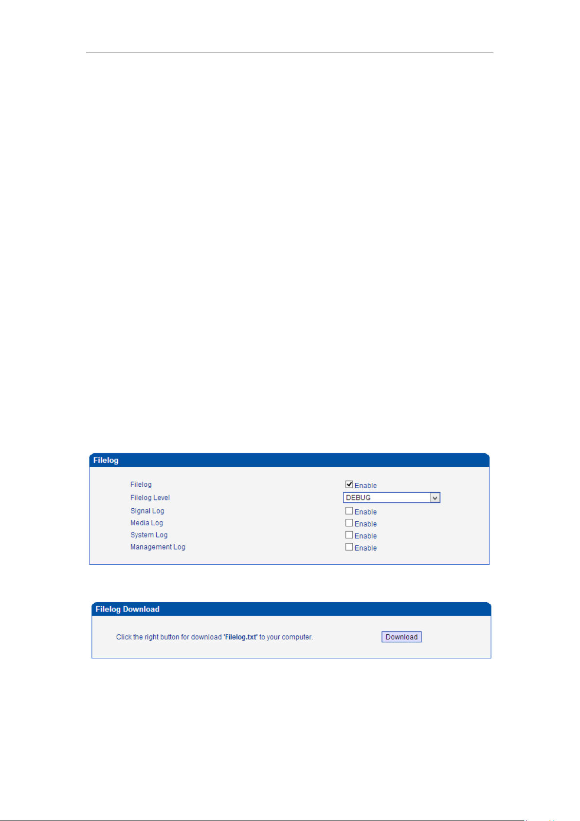
DWG2000E/F/G GSM/CDMA VoIP Gateway User Manual
- ECC, detail information of call control module
- RE, the common communication module for SCP and SIM
- SCP, the communication protocol between gateway and cloud server
The media log is include following traces which defined in system by default
- RTP, RTP stream info collection
- SIM, to output traces between gateway and remote SIM cards
The System Log is include following traces which mainly used by developer
- SYS, system log
- TIMER, system process
- TASK, system task process
- CFM, system process
- NTP
The Management Log is include following traces which defined in system by default
- CLI, command line
- TEL,
- LOAD, firmware upload
- SNMP
- WEBS, embedded web server
- PROV, provisioning
Server Syslog:
When the gateway register to SIM Cloud server, the option will be changed to unconfigurable
and all logs to be storage on server.
4.14.3 Filelog /Filelog Download
The main difference between Filelog and syslog is, Filelog stores in local internal memory but
syslog output external server. The log contents are the same as syslog.
4.14.4 Management Parameter
Figure 4-14-2 Management Parameter
_______________________________________________________________________________
Shenzhen Dinstar Technologies Co., Ltd.
67
Page 69
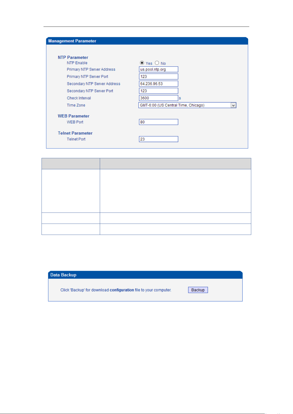
DWG2000E/F/G GSM/CDMA VoIP Gateway User Manual
Parameters
Description
NTP Parameter
The Network Time Protocol (NTP) is a protocol and software
implementation for synchronizing the clocks of computer systems
over packet-switched, variable-latency data networks.
User need to fill the NTP Server Address and select Time Zone
Web Port
Default is 80
Telnet Port
Default is 23
Table 4-14-1 Management Parameter
4.14.5 Config Backup
Figure 4-14-3 Data backup
Click 'Backup' to download configuration file to your computer.
4.14.6 Config Restore
Figure 4-14-4 Config Restore
_______________________________________________________________________________
Shenzhen Dinstar Technologies Co., Ltd.
68
Page 70
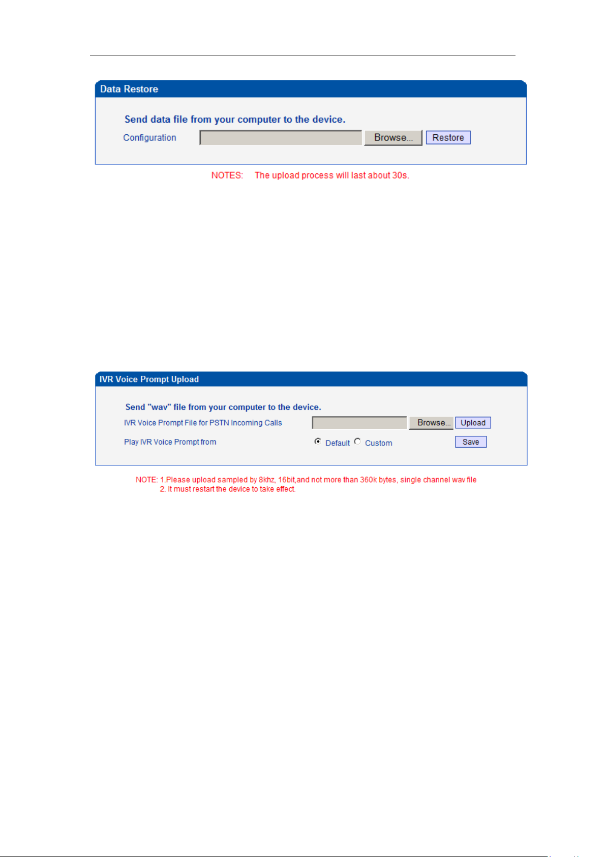
DWG2000E/F/G GSM/CDMA VoIP Gateway User Manual
You can restore this configuration in case the unit loses it for any reason or to clone a unit with
the configuration of another unit. The configuration backup configurations are in txt format.
Please note that you can use a backup file from an older firmware version and use it in a unit
with a more recent firmware version. However, a backup file from a newer firmware version
than the one actually in the unit cannot be used for a restore operation on the unit.
4.14.7 IVR Voice Prompt Upload
By default, when PSTN call incoming, the system will play the default IVR, and also the user
can load custom IVR.
Figure 4-14-5 IVR Voice Prompt Upload
NOTE: the customize voice files can be recorded using Windows recording programs, the
sound format is 8000Hz, 16 bit sampling in mono, with WAV format, size of files cannot be
exceed 190KB
4.14.8 Ping Test
Ping is utility used to test the reach ability of a host on an Internet Protocol (IP) network and to
measure the round-trip time for messages sent from the originating host to a destination host.
Figure 4-14-6 Ping Test
_______________________________________________________________________________
Shenzhen Dinstar Technologies Co., Ltd.
69
Page 71
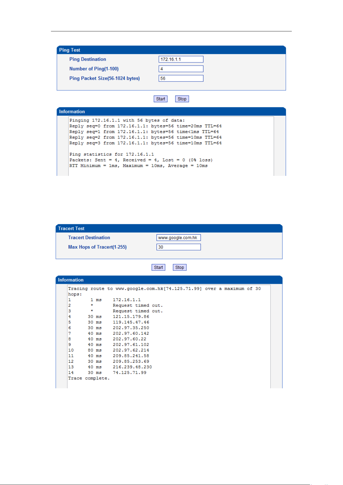
DWG2000E/F/G GSM/CDMA VoIP Gateway User Manual
4.14.9 Tracert Test
Tracert is a computer network diagnostic tool for displaying the route (path) and measuring
transit delays of packets across an Internet Protocol (IP) network.
Figure 4-14-7 Tracert Test
4.14.10 Network Capture
Network capture is a very important diagnostic tool for maintenance. This section is describes
_______________________________________________________________________________
Shenzhen Dinstar Technologies Co., Ltd.
70
Page 72
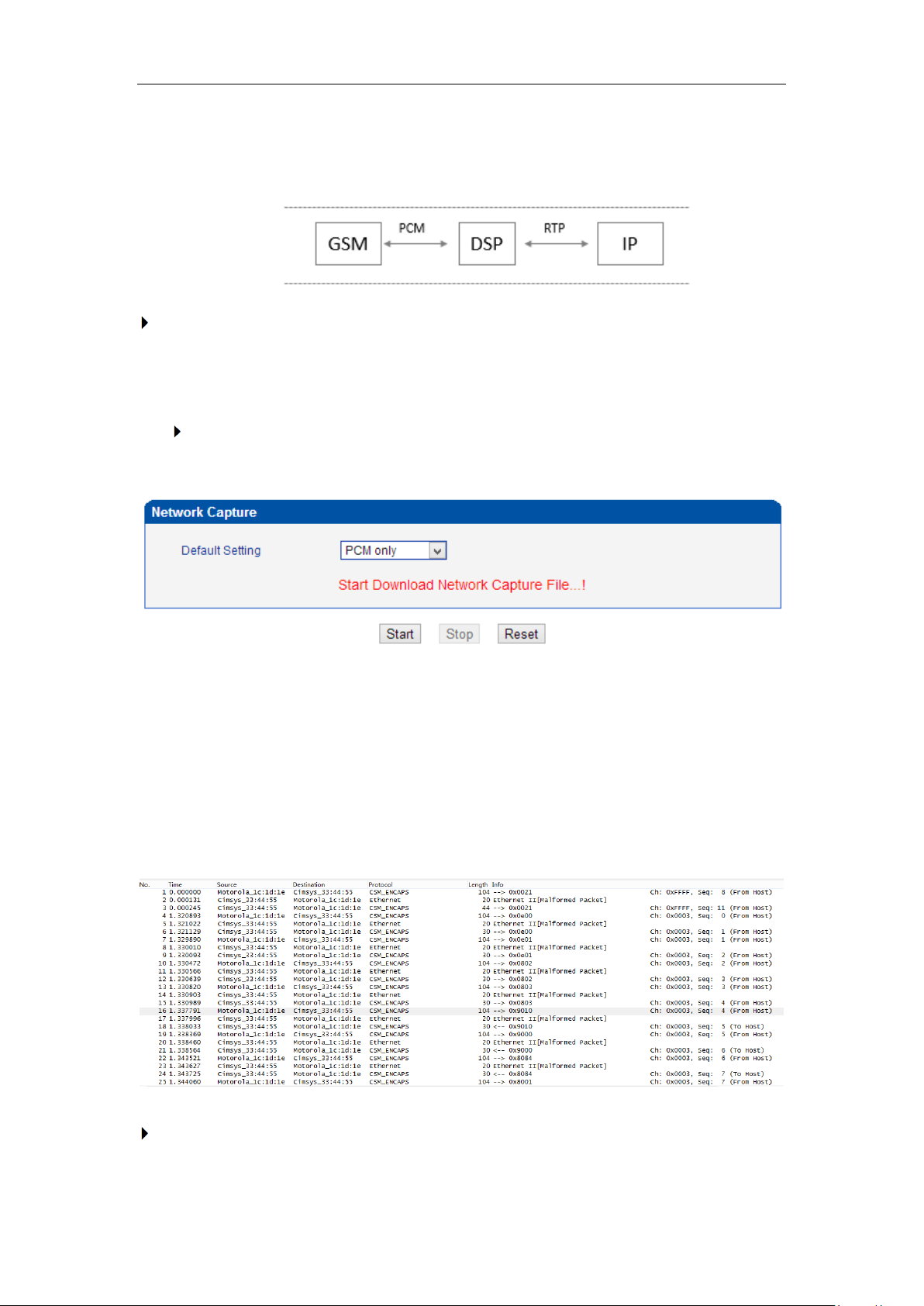
DWG2000E/F/G GSM/CDMA VoIP Gateway User Manual
how to enable network capture.
Voice stream transmit path of the gateway as below:
Getting start to PCM capture
PCM capture is help to analysis voice stream between GSM/CDMA module and DSP
chipset.
To enable PCM capture
Select ‘PCM only’ on Network Capture page
Click “Start’ to enable PCM capture
Dialing out through gateway, start talking a short while then hangup the call.
Click ‘Stop’ to disable network capture
Save the capture file to local computer
The capture is named to ‘capture(x).pcap’, x is serial number of capture and will be added
1 in next time. The sample of PCM capture as below:
Getting start to Syslog capture
_______________________________________________________________________________
Shenzhen Dinstar Technologies Co., Ltd.
71
Page 73
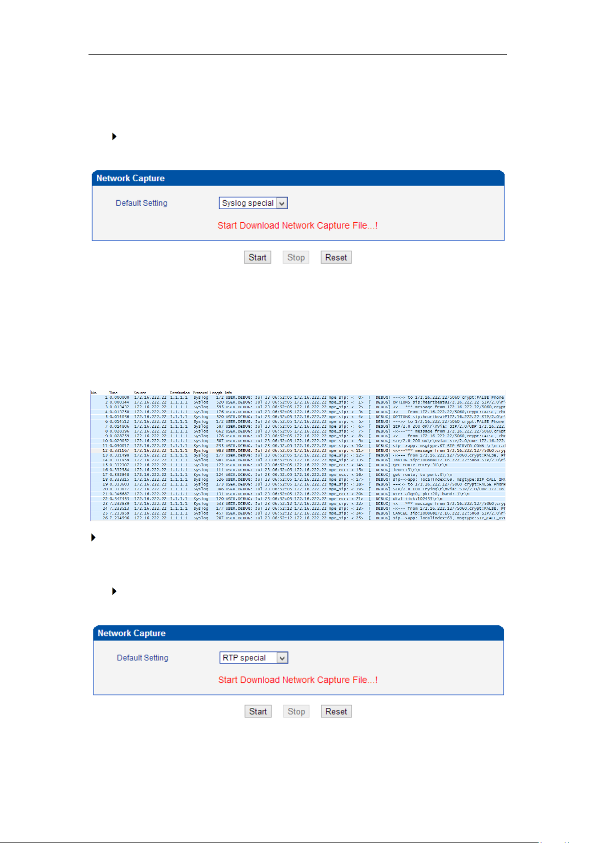
DWG2000E/F/G GSM/CDMA VoIP Gateway User Manual
Syslog capture is another way to obtain syslog which the same as remote syslog server
and filelog. The capture file is save as pcap format so that it can be opened in some of
capture software like Wireshark, Ethereal software etc.
To enable syslog capture
Select Syslog special only on Network Capture page
Click “Start’ to enable syslog capture
Dialing out through gateway, start talking a short while then hangup the call.
Click ‘Stop’ to disable syslog capture
Save the capture to local computer
The capture is named to ‘capture(x).pcap’, x is serial number of capture and will be added
1 in next time. The sample of syslog capture as below:
Getting start to RTP capture
PCM capture is help to analysis voice stream between gateway and remote IPPBX/SIP
Server.
To enable RTP capture:
Select RTP special on Network Capture page
Click Start to enable RTP capture
_______________________________________________________________________________
Shenzhen Dinstar Technologies Co., Ltd.
72
Page 74
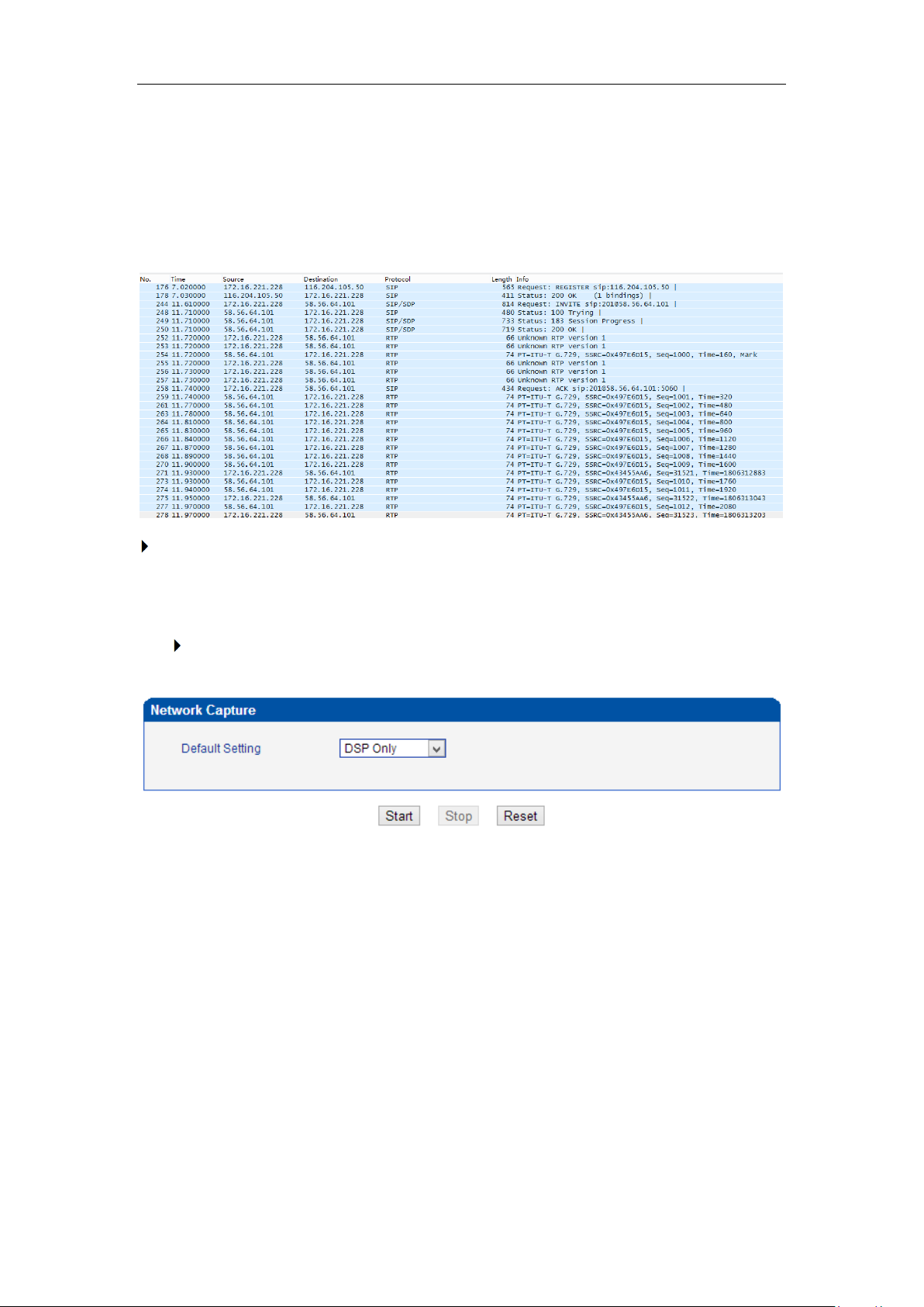
DWG2000E/F/G GSM/CDMA VoIP Gateway User Manual
Dialing out through gateway, start talking a short while then hangup the call.
Click Stop to disable RTP capture
Save the capture to local computer
The capture is named to ‘capture(x).pcap’, x is serial number of capture and will be added 1
in next time. The sample of RTP capture as below:
Getting start to DSP capture
DSP capture is help to analysis voice stream inside DSP chipset. The DSP chipset will
handle RTP from IP network as well as voice stream from GSM/CDMA module.
To enable DSP capture:
Select DSP only on Network Capture page
Click Start to enable DSP capture
Dialing out through gateway, start talking a short while then hangup the call.
Click Stop to disable DSP capture
Save the capture to local computer
The capture is named to ‘capture(x).pcap’, x is serial number of capture and will be added
1 in next time. The sample of RTP capture as below:
_______________________________________________________________________________
Shenzhen Dinstar Technologies Co., Ltd.
73
Page 75
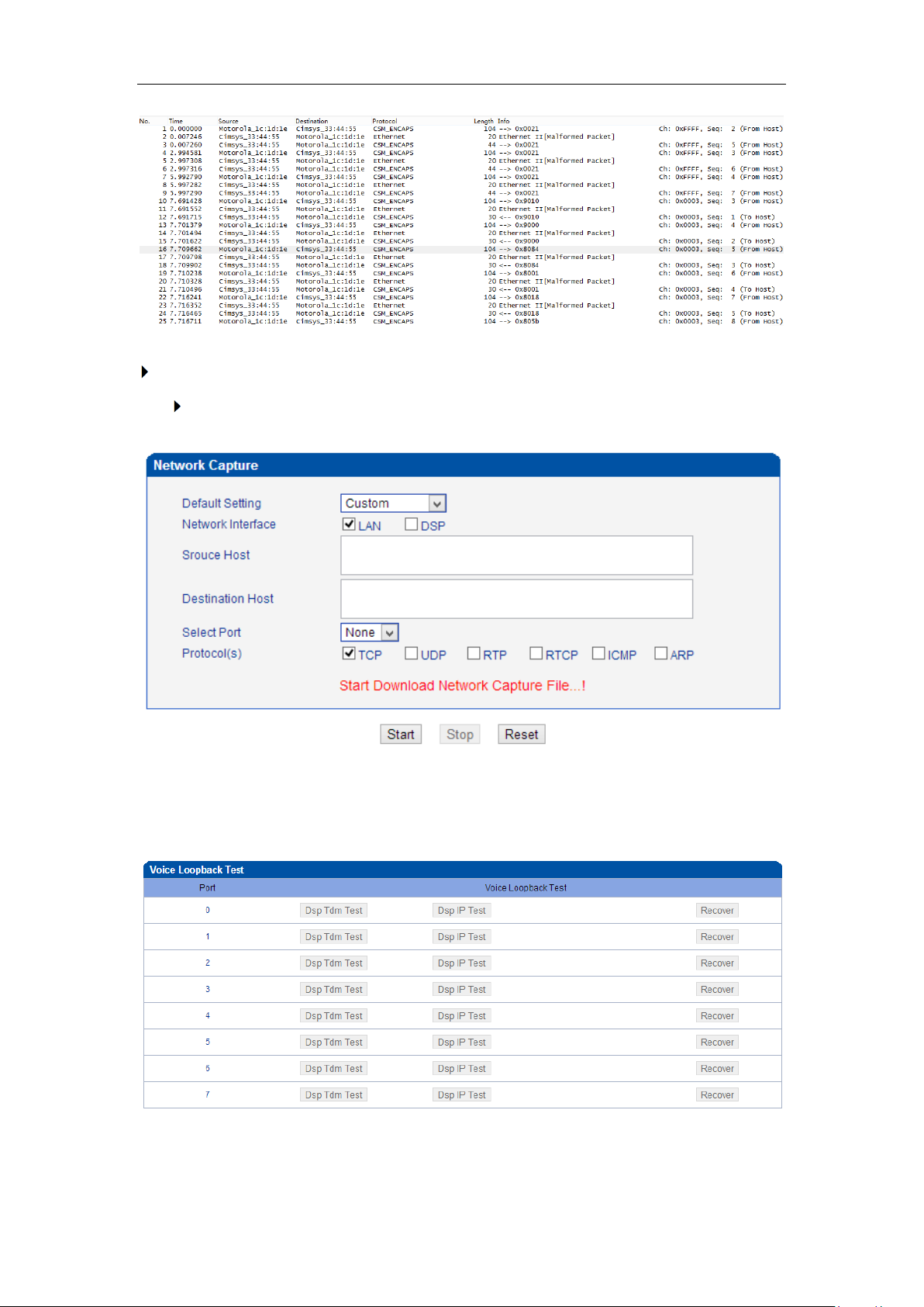
DWG2000E/F/G GSM/CDMA VoIP Gateway User Manual
Configurable capture options
Getting start to custom capture
This menu provides more options to capture specific packets as actually needs.
4.14.11 Voice Loopback Test
Voice Loopback test should be done on call status. Each call can do one kind of test. After
each test, please hang up and call again, refresh web interface and go on the other tests.
Voice stream patch on gateway:
_______________________________________________________________________________
Shenzhen Dinstar Technologies Co., Ltd.
74
Page 76
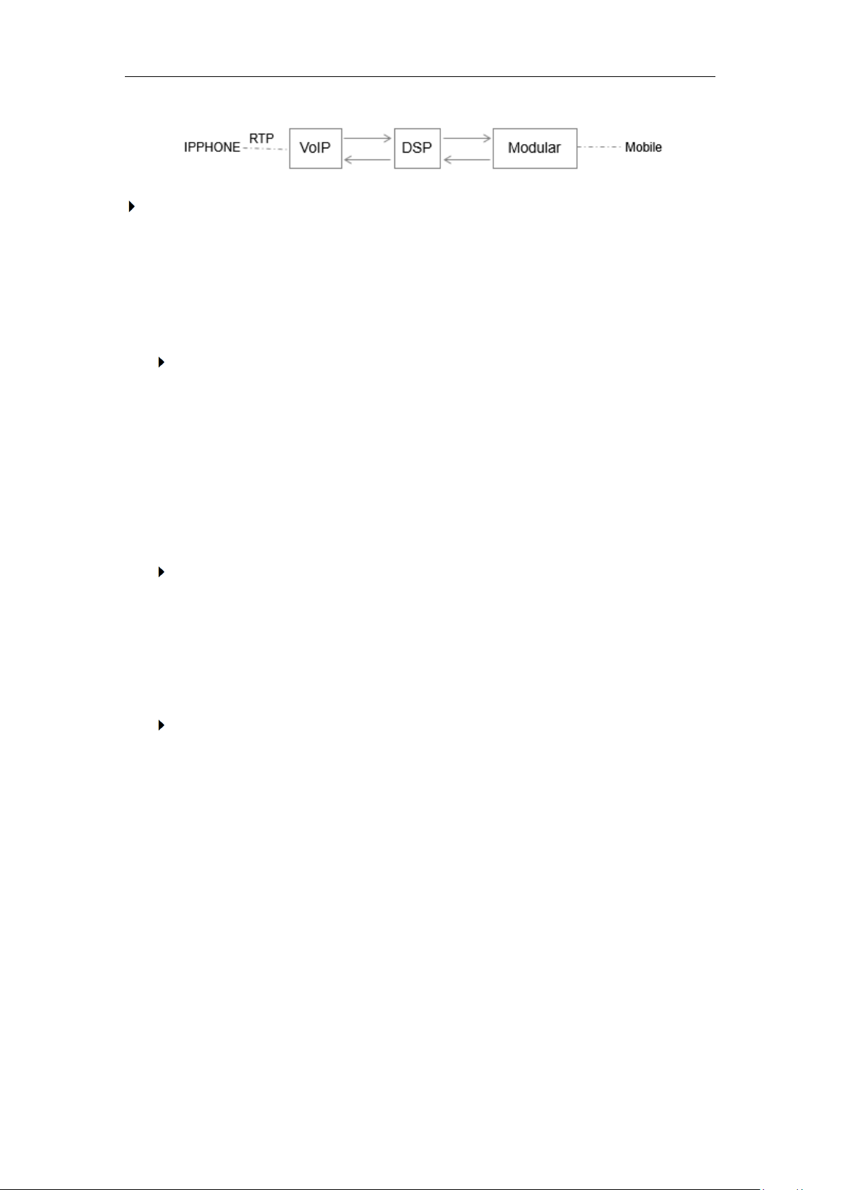
DWG2000E/F/G GSM/CDMA VoIP Gateway User Manual
DSP Tdm Test
DSP TDM Test is the loopback of GSM side.
VoIP <-----DSP<----- Module<------ Mobile
-----> ------> ------->
To start DSP TDM Test:
Make a call test through gateway, the call can be initialed by IPPHONE. Keep the
conversation after call establish
Click DSP TDM Test to start test
Check the voice on both sides. VoIP side become silence and echo should be
generated on Mobile phone side
Hangup
To start DSP IP Test:
DSP IP Test is the loopback of VoIP side.
IPHONE------>VoIP-------> DSP
<------ <-------
To start DSP IP Test:
Make a call test through gateway, the call can be initialed by IPPHONE. Keep the
conversation after call establish
Click DSP IP Test to start test
Check the voice on both sides. GSM side become silence and echo should be
generated on IPPHONE side
Hangup
4.14.13 Username & Password
Figure 4-14-13 Username and Password
_______________________________________________________________________________
Shenzhen Dinstar Technologies Co., Ltd.
75
Page 77
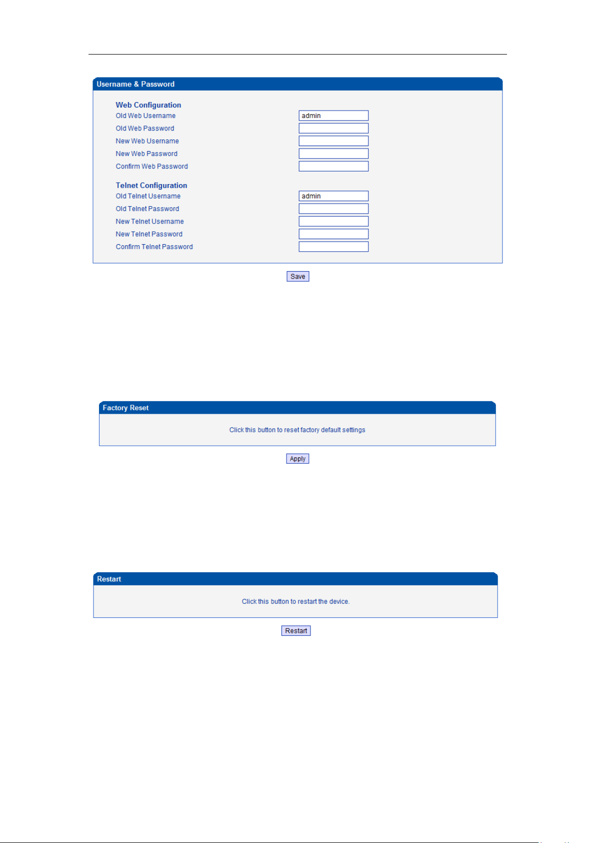
DWG2000E/F/G GSM/CDMA VoIP Gateway User Manual
When using web or telnet Configuration, please enter default user name and password. User
can modify the login name and password.
4.14.14 Factory Reset
Figure 4-14-14 Factory Reset
Be careful do this operation, after restore factory setting, all the parameters will be changed to
the factory default.
4.14.15 Restart
Figure 4-14-15 Restart
_______________________________________________________________________________
Shenzhen Dinstar Technologies Co., Ltd.
76
Page 78
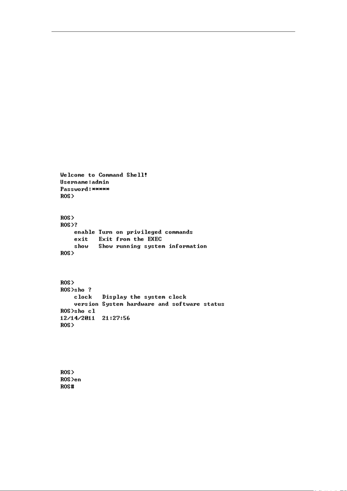
DWG2000E/F/G GSM/CDMA VoIP Gateway User Manual
5. Troubleshooting and Command Line
5.1 Login DWG & General Knowledge of DWG Command
This is a document for some customers who need more details of DINSTAR’s products with
command lines. To make sure the system runs successfully, we suggest customers setting
DWG by GUI. In this manual, some topics such as how to check the IP, signaling and call
conversation are covered.
Tips: The document is fit for all DWG2000E/F/G models.
Run system tool Telnet to login DWG. The default username and password is "admin".
C:\Users\Administrator>telnet 172.16.101.142
Input "?" to show the all commands and its information.
Abbreviation is supported in DWG command. For example you can input "en" substitute for
"enable", input "sh" substitute for "show", input "cl" substitute for "clock",
5.2. Commands in "ROS#" Mode
There is only a litter commans in "ROS>" mode. If you need more commands you must enter
the "ROS#" mode. Input "enable" to enter "ROS#" mode if you have in the "ROS>" mode.
5.2.1 Summarize of commands in "ROS#" mode
Input "?" to get the information of all commands in "ROS#" mode.
_______________________________________________________________________________
Shenzhen Dinstar Technologies Co., Ltd.
77
Page 79
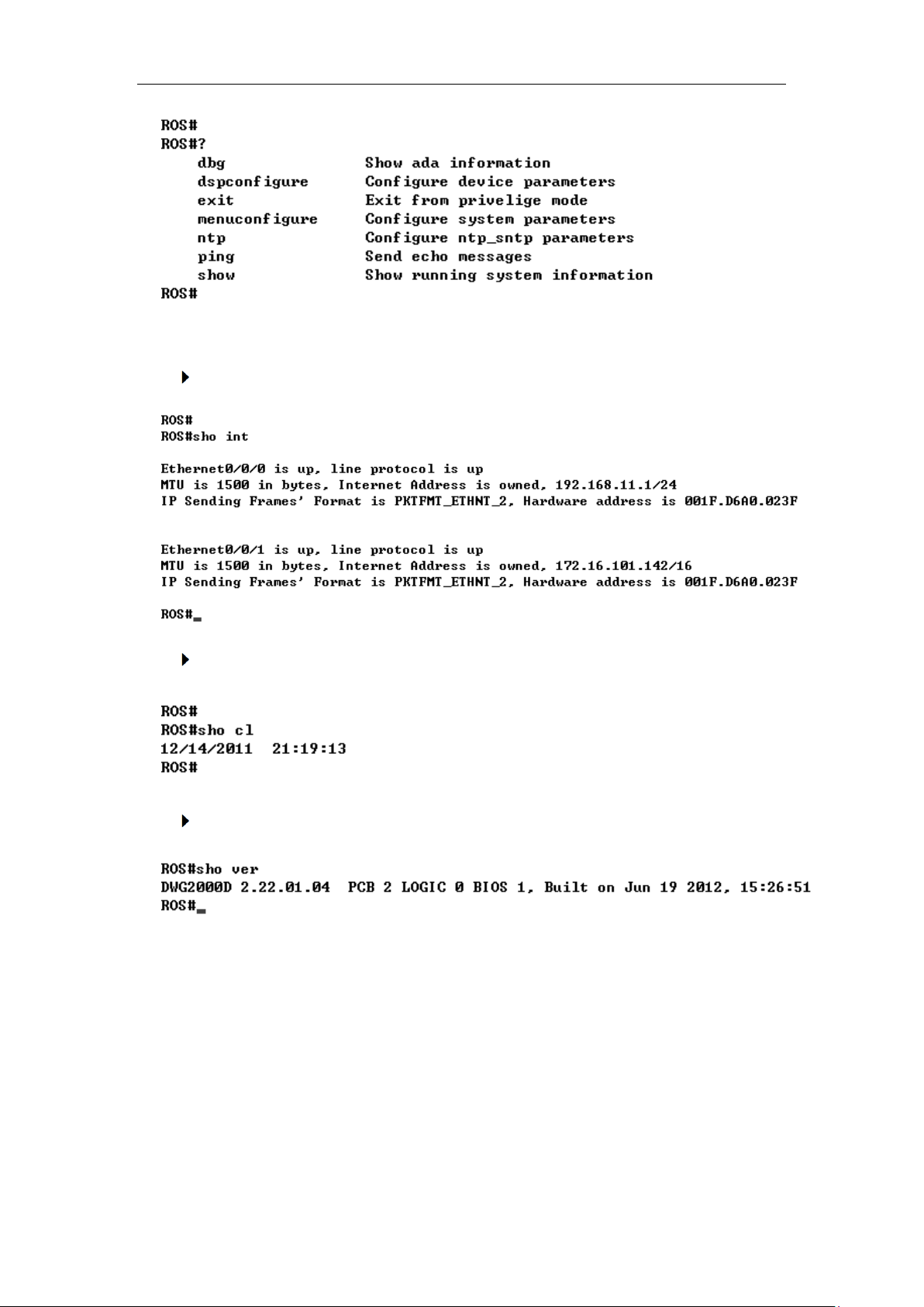
DWG2000E/F/G GSM/CDMA VoIP Gateway User Manual
5.2.2 General Purpose Commands in "ROS#" mode
Show IP address (show int)
Show Time (show clock)
Show version (show version)
_______________________________________________________________________________
Shenzhen Dinstar Technologies Co., Ltd.
78
Page 80
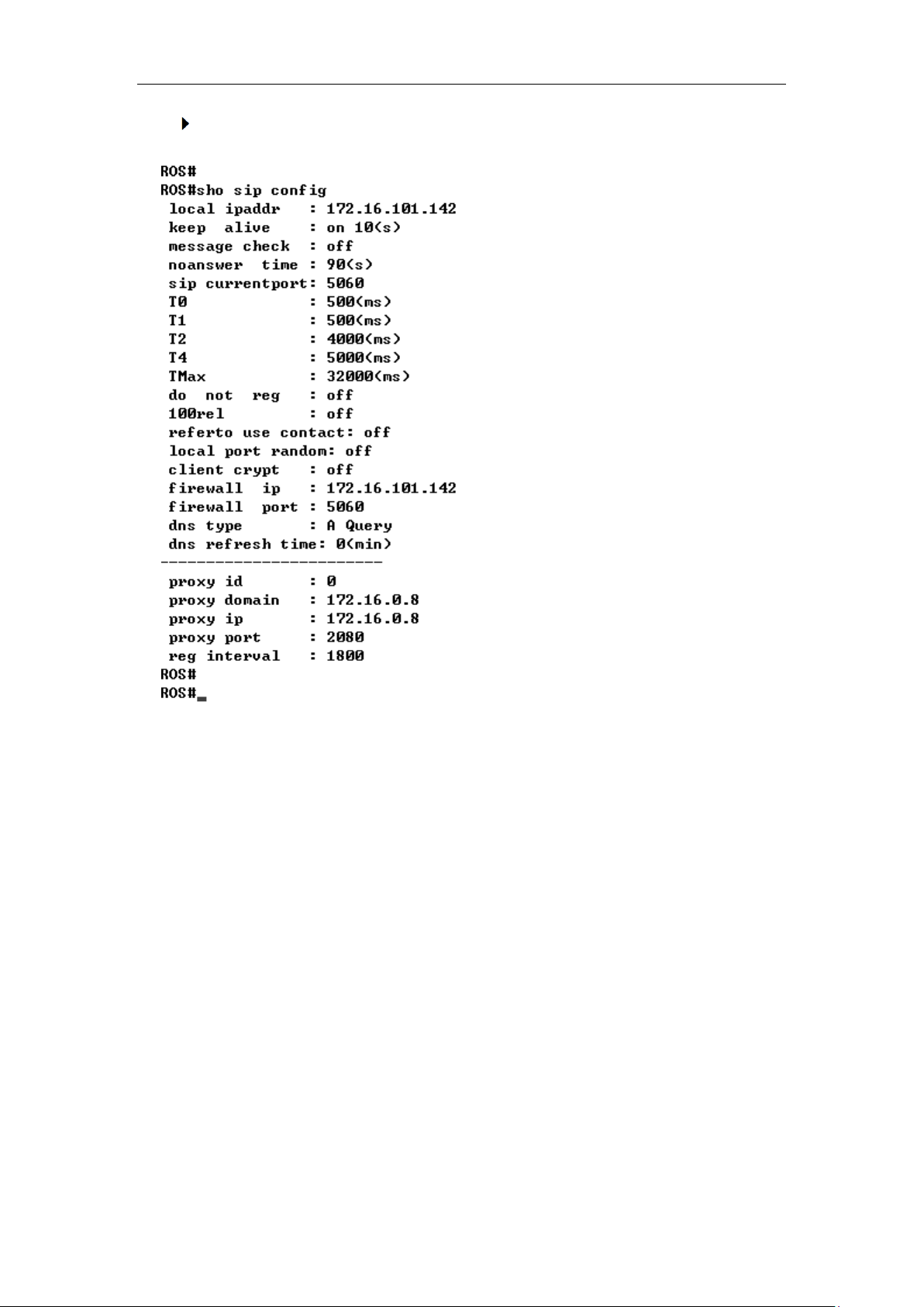
DWG2000E/F/G GSM/CDMA VoIP Gateway User Manual
Show sip Information (show sip config)
_______________________________________________________________________________
Shenzhen Dinstar Technologies Co., Ltd.
79
Page 81
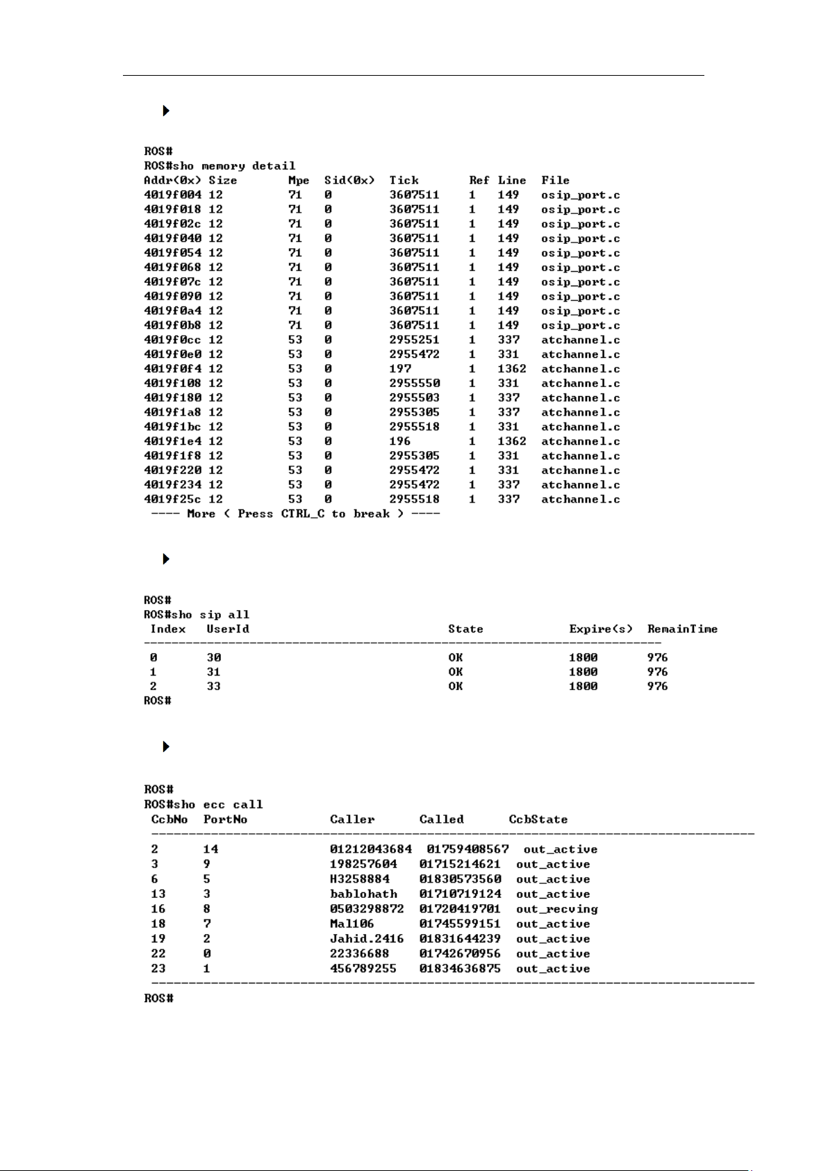
DWG2000E/F/G GSM/CDMA VoIP Gateway User Manual
Show memory status (show memory detail)
Show SIP port status (show sip all)
Show Current calls (sh ecc call)
_______________________________________________________________________________
Shenzhen Dinstar Technologies Co., Ltd.
80
Page 82
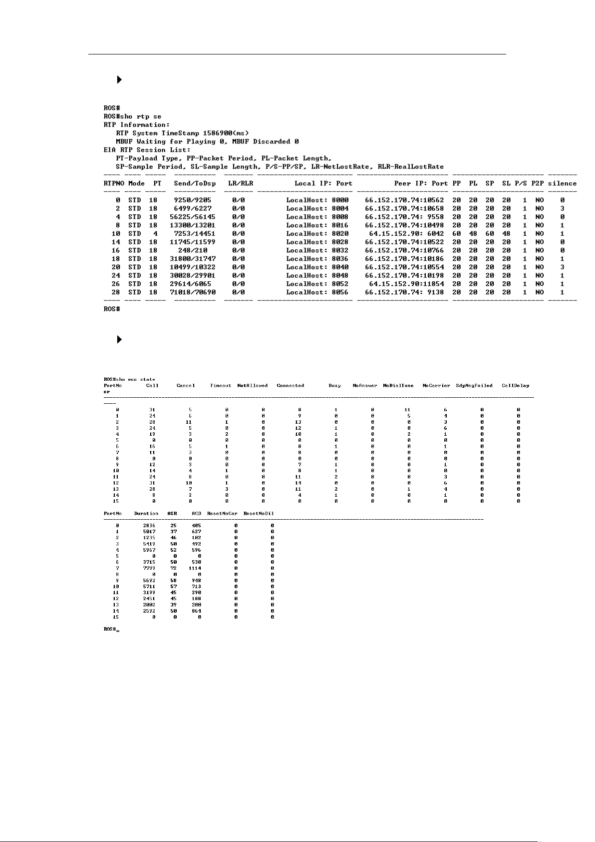
DWG2000E/F/G GSM/CDMA VoIP Gateway User Manual
Show RTP session ( sho rtp se)
Show ASR/ACD statistics (show ecc state)
5.3 Commands in "Config" Mode
5.3.1 Summarize of commands in "config" mode
Input "^config" in the "ROS# " to enter "config" mode.
_______________________________________________________________________________
Shenzhen Dinstar Technologies Co., Ltd.
81
Page 83
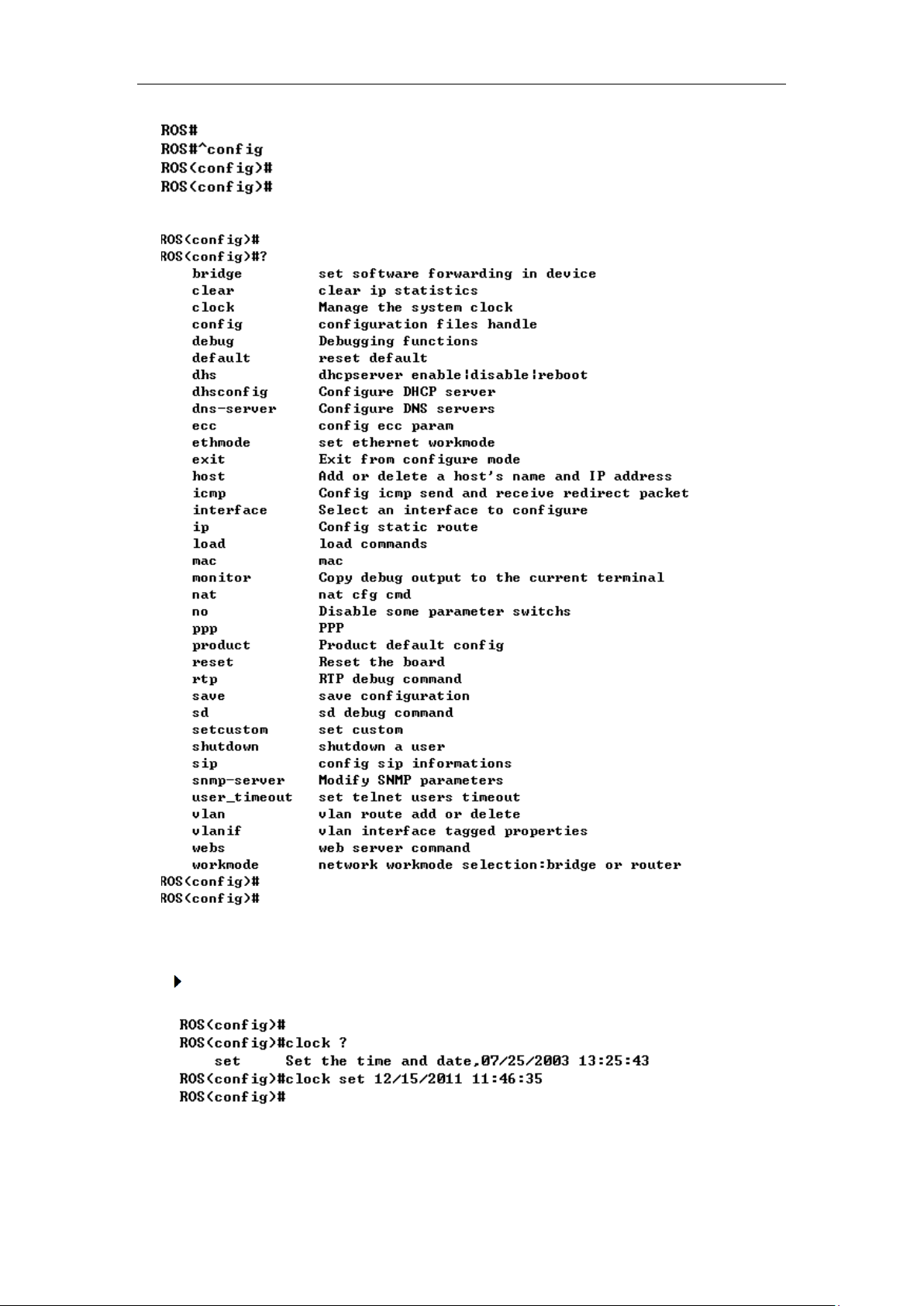
DWG2000E/F/G GSM/CDMA VoIP Gateway User Manual
Input "?" to show the all commands and its information.
5.3.2 General Purpose Commands in "Config" mode
Set time (clock set)
_______________________________________________________________________________
Shenzhen Dinstar Technologies Co., Ltd.
82
Page 84
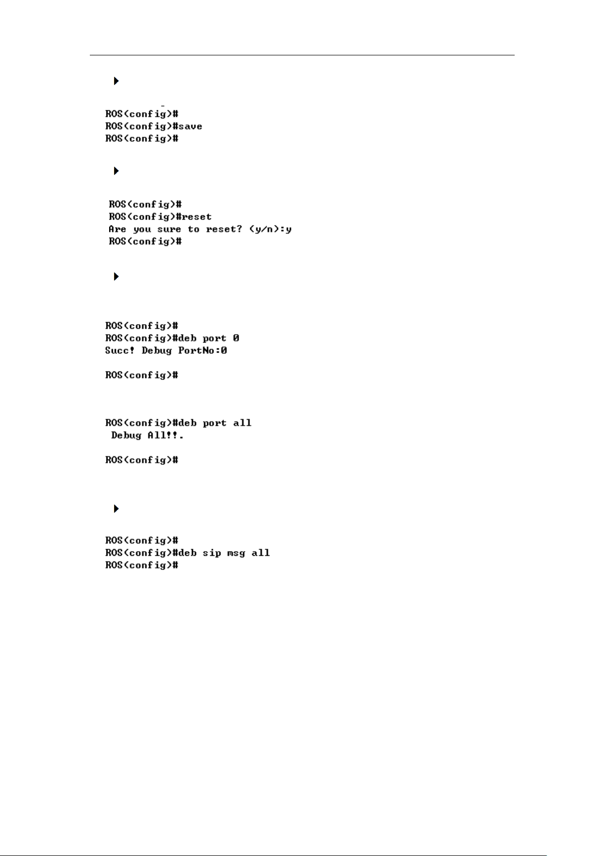
DWG2000E/F/G GSM/CDMA VoIP Gateway User Manual
Save the configuration (save)
Restart device (reset eia)
Enable debug
The command format is deb port + port number, to enable port 0 debug, as below:
To enable all ports debug, with the command “deb port all”
Without this steps, no trace logs will display on output window
Enable SIP debug (deb sip msg all)
5.4 How to trace SIP logs
Create telnet session to gateway, the main steps as below:
Welcome to Command Shell!
Username:admin
Password:*****
ROS>en
ROS#
ROS#^config
ROS(config)#deb sip msg all
ROS(config)#ex
_______________________________________________________________________________
Shenzhen Dinstar Technologies Co., Ltd.
83
Page 85

DWG2000E/F/G GSM/CDMA VoIP Gateway User Manual
ROS#
ROS#^ada
ROS(ada)#ADA CONNECTED ...,WELCOME!
ROS(ada)#
ROS(ada)#turnon 71
Disable sip trace:
ROS(ada)#turnoff 71
5.5 How to trace ECC logs (Call Details)
Welcome to Command Shell!
Username:admin
Password:*****
ROS>en
ROS#
ROS#^config
ROS(config)#deb port all
Debug All!!.
//enable trace on all port
ROS(config)#
ROS(config)#deb port 0
Succ! Debug PortNo:0
// enable trace port 0
ROS(config)#
ROS(config)#no deb port all
ROS(config)#
ROS(config)#ex
ROS#^ada
ROS(ada)#ADA CONNECTED ...,WELCOME!
ROS(ada)#turnon 84
Disable trace:
ROS(ada)#turnoff 84
5.6 How to trace Module logs
Welcome to Command Shell!
Username:admin
Password:*****
ROS>en
ROS#^ada
ROS(ada)#ADA CONNECTED ...,WELCOME!
ROS(ada)#cmd 53 19 0 0 1
_______________________________________________________________________________
Shenzhen Dinstar Technologies Co., Ltd.
84
Page 86

DWG2000E/F/G GSM/CDMA VoIP Gateway User Manual
// enable trace. 0 0 means port range 0 to 0, 0 8 means port range from 0 to 8; 1
means enable module trace
ROS(ada)#cmd 53 19 0 0 0
//disable module trace
_______________________________________________________________________________
Shenzhen Dinstar Technologies Co., Ltd.
85
Page 87
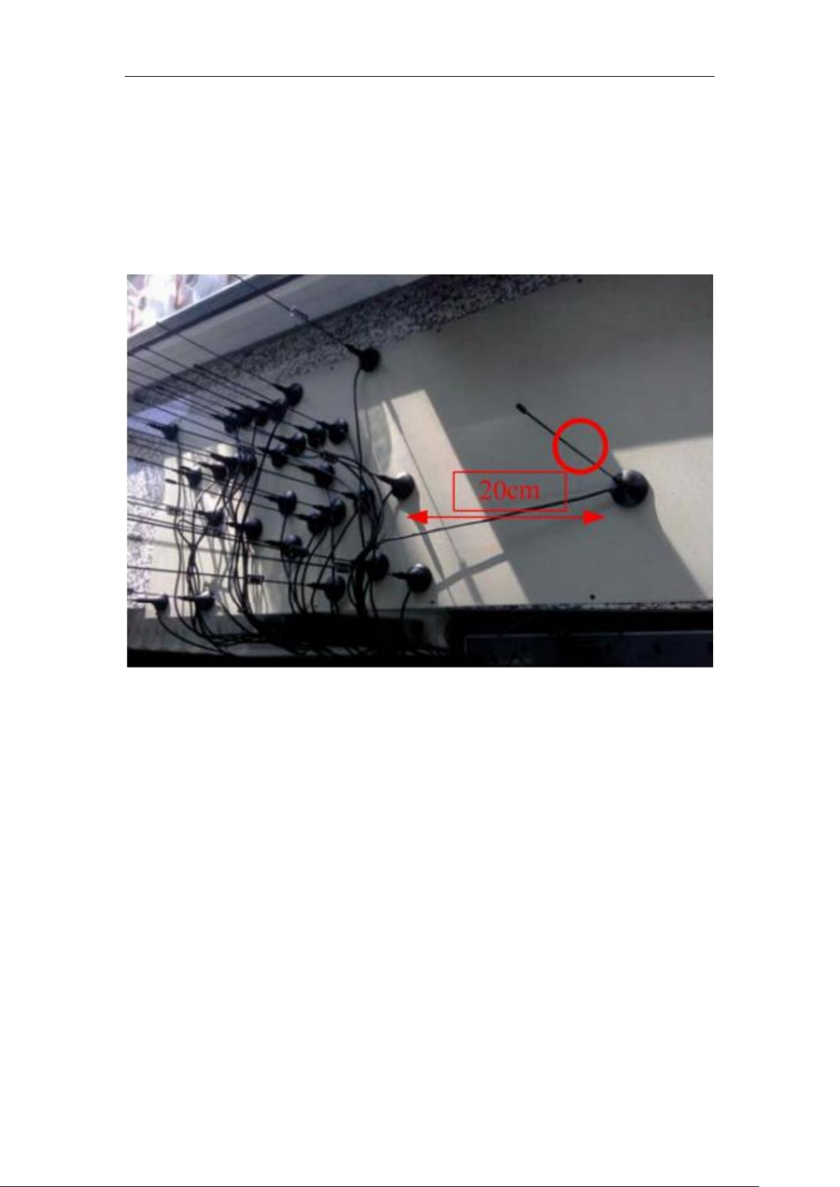
DWG2000E/F/G GSM/CDMA VoIP Gateway User Manual
6. The Way to Increase Antenna Isolation
Several methods are introduced in this document to decrease the interfering effect
among antennas with close mounting position.
6.1 Isolate by distance
figure-6.1 Theoretic distance value for GSM band
Keep distance between antennas as far as possible. In theory, the distance between
antennas should be more than half of the operating wavelength. For GSM band, the
recommended distance value is more than 20cm.in practical application, the
experiment value is no less than 15cm for better isolation.
6.2 Isolate by metal shielding baffles among antenna
Put a metal shielding baffle between antennas, which can help to prevent radiation
signal coupling from each other. If the metal baffle is big enough, the isolation
will be unlimited big in theory.
Figure 6.2 Isolation by metal shielding baffles
_______________________________________________________________________________
Shenzhen Dinstar Technologies Co., Ltd.
86
Page 88
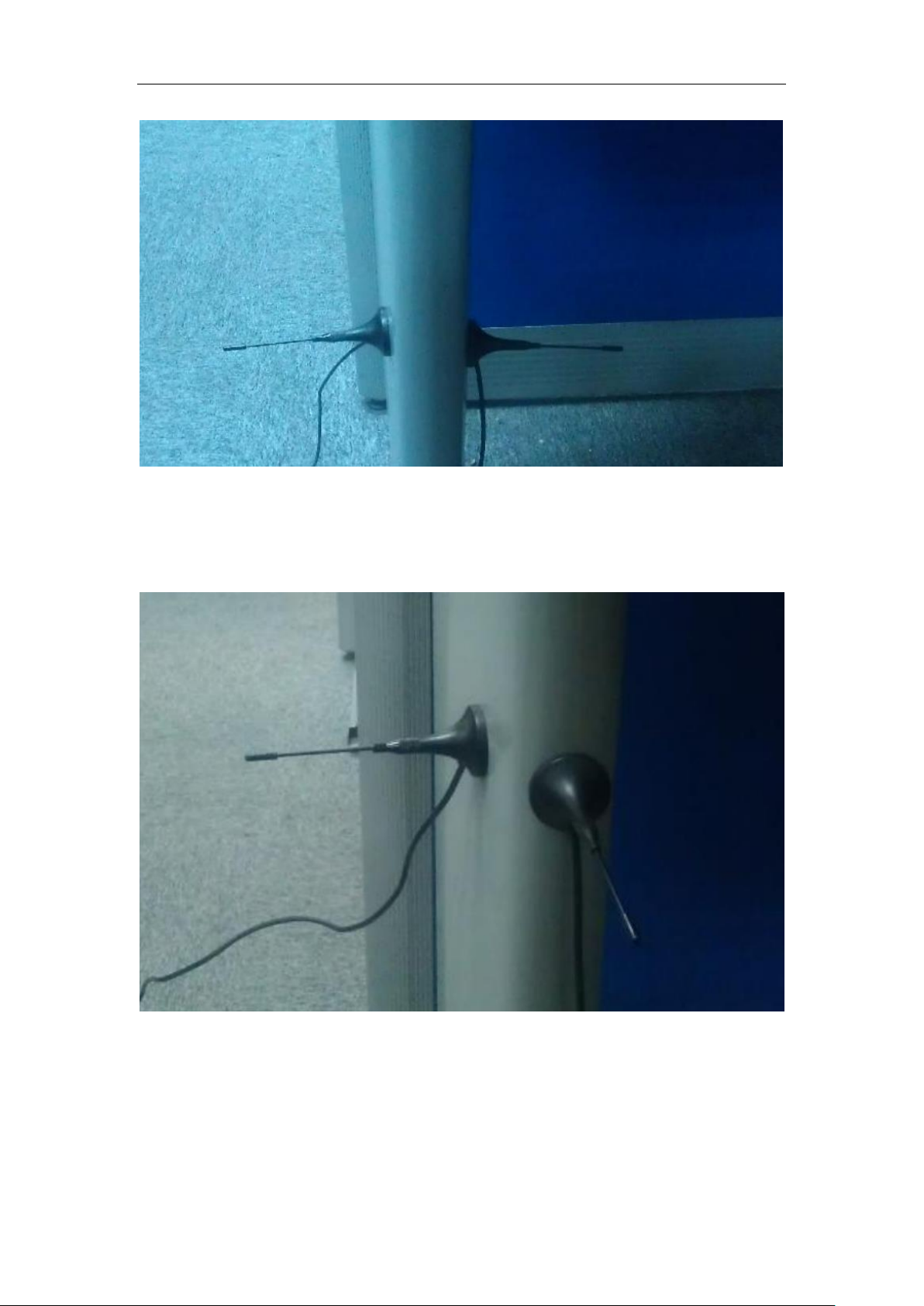
DWG2000E/F/G GSM/CDMA VoIP Gateway User Manual
6.3 Isolate by antenna orthogonal polarization
Figure 6.3 Isolation by antenna orthogonal polarization
In theory, the isolation is unlimited big if the polarization is really orthogonal, like
vertical polarization VS horizontal antenna; RHCP (Right Hand Circular Polarization)
VS LHCP (Left Hand Circular Polarization).
_______________________________________________________________________________
Shenzhen Dinstar Technologies Co., Ltd.
87
Page 89
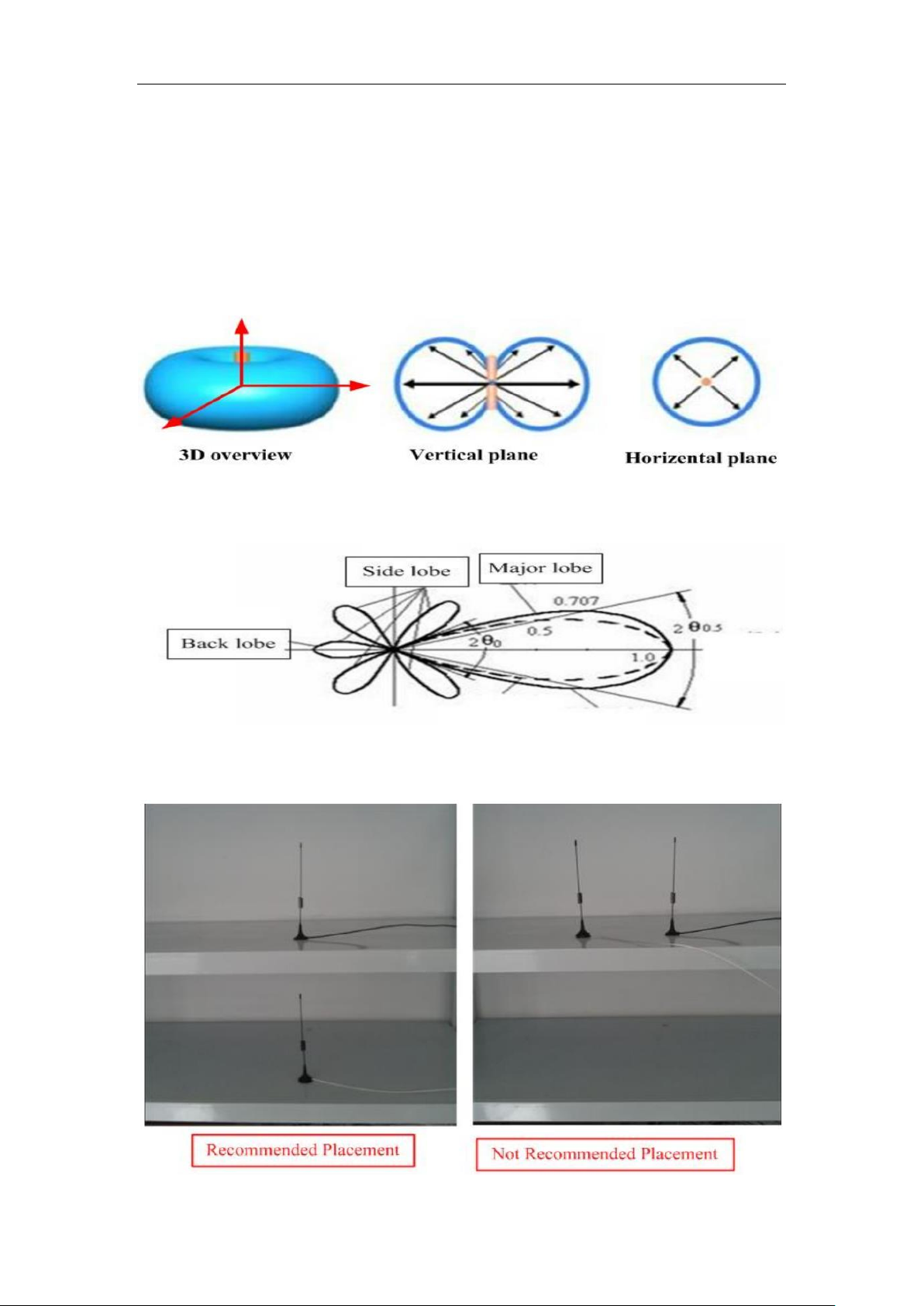
DWG2000E/F/G GSM/CDMA VoIP Gateway User Manual
In real practical application, the antenna are all elliptic polarization, they have a
certain ratio. So putting the same type antennas in orthogonal position will be helpful
for isolation.
6.4 Isolate by antenna radiation pattern
Radiation pattern of low directivity antenna
radiation pattern of high directivity antenna
Recommended placement with nonmetal shelf
_______________________________________________________________________________
Shenzhen Dinstar Technologies Co., Ltd.
88
Page 90

DWG2000E/F/G GSM/CDMA VoIP Gateway User Manual
Try to modify the antenna mounting position, avoid the major lobe of both antenna
overlap, which is also an effective way for high isolation among different antennas,
especially for high directivity antenna.
It might be difficult to find a perfect position to stagger the major lobe for low directivity
antennas, two factors cause this, one is the major lobe is very broad, the other is the
radiation pattern is affected by surroundings sensitively.
For common antenna we often use, most of them belong to low directivity type, we
can put the antennas in a nonmetal shelf, and place antennas in vertical form, not in
horizontal form, which can help to avoid antennas major lobe overlap and make the
isolation bigger in some degree.
7. Frequency Asked Questions
7.1 Device have been connected to network physically, but cannot access the
gateway
1) Make sure the network cable is ok , can through view the device network port indicator
light to determine the physical connection is working or not;
2) Make sure the connected network devices (router, switch or hub) support 10M/100M
adaptive, if not, connect the Equipment directly to PC, landing WEB and in the "local
connection" Configuration interface Select the correct Ethernet Work Mode;
3) Check the Network Configuration, if the Configuration is incorrect, please
re-Configuration. If you are using DHCP mode, check DHCP Server is working properly;
4) Check whether there is a LAN device conflict with the exists IP ADDRESS.
7.2 Equipment can not register
If the Run LED does not flash mean unregistered
1) Check the network connection is working (see above section), whether the Configuration
is correct;
2) Check whether the LAN firewall setting is inappropriate (such whether limit the network
communication); If it is, there are two ways to try to resolve;
3) Check whether the Local Network to the SIP PROXY platform network environment is
relatively poor or not, and if so, please check Local Network or contact the service provider;
4) if go through those steps, the device still be in trouble, please contact the equipment
_______________________________________________________________________________
Shenzhen Dinstar Technologies Co., Ltd.
89
Page 91

DWG2000E/F/G GSM/CDMA VoIP Gateway User Manual
provider;
7.3 When calling out, the callee’s phone shows wrong caller ID
1) Ask the callee checks whether the device is failure or device battery power is low
2) Make sure the callee has been subscribed called User ID display service
3) If only part of the caller User ID with this problem, please contact the telecom carrier.
7.4 Sudden interruption during a call
1) make sure whether is human error caused the problem
2) Check the balance.
3) Make sure whether the LAN equipment such as gateway or router fails, user can try to
restart the gateway or router
7.5 Voice single-pass, double-barrier or poor quality
1) Make sure the equipment is working properly with grounded power
2) Check the device network connection is in working status
3) Ask network administrators to open limitation with the equipment’s network
communications (it is a special equipment, not afraid of virus attacks); (2) try to enable the
equipment tunnel (through the WEB for Configuration, Also, please NOTE, open the
tunnel will impact voice quality, Please do not enable the tunnel as far as possible, refer
WEB Configuration Interface Description section)
4) Make sure the LAN equipment is working, user can try to restart the gateway or router to
solve the problem
5) Check whether there is more than one DINSTAR series products in LAN network: some
gateways or routers, processing network packet is vulnerable (for example, to multiple
network devices or the same protocol network communication, NAT allocated the same
conversion communications Channel). If there is such a case, suggest replacing a router or
specify each voice gateway with different LOCAL RTP PORT Channel (refer to the base
WEB Configuration interface section)
6) Check the equipment network environment for the softswitch platform, monitor the
network condiation, make sure the network is solid
_______________________________________________________________________________
Shenzhen Dinstar Technologies Co., Ltd.
90
Page 92

DWG2000E/F/G GSM/CDMA VoIP Gateway User Manual
8. Glossary
GSM: Global System for Mobile Communications
CDMA: Code Division Multiple Access
FMC: Fixed Mobile Convergence
SIP: Session Initiation Protocol
MGCP: Media Gateway Control Protocol
DTMF: Dual Tone Multi Frequency
USSD: Unstructured Supplementary Service Data
PSTN:Public Switched Telephone Network
STUN: Simple Traversal of UDP over NAT
IVR: Interactive Voice Response
IMSI: International Mobile Subscriber Identification Number
IMEI: International Mobile Equipment Identity
DMZ: Demilitarized Zone
API: Application programming Interface
BCCH: Broadcast Control Channel
LAC: Location Area Code
CID: Cell ID
BTS: Base Transceiver Station
DTMF: Dual-Tone Multifrequency
IVR: Interactive Voice Response
NAT: Network Address Translation
RTP: Real-time Transport Protocol
VoIP: Voice over IP
_______________________________________________________________________________
Shenzhen Dinstar Technologies Co., Ltd.
91
 Loading...