

DINSE DIX WF 793.M Operation Manual
BA-0132
Operations manual
Keep in secure area for future reference!
SCHWEISSEN WELDING
Wire feeder
DIX WF 793.M
WELDINGSCHWEISSEN SCHWEISSEN
Introduction 2
Description 2
Technical data 2
How to lift up the system 2
Opening the packaging 2
Installation and connections 2
Loading wire 3
Assembly of drive rolls 3
Command and control units (Fig. A) 3
Before welding 3
Optional 4
Maintenance and trouble shooting 4
Replacing the motor control board 4
Simple automation 4
Welding defects 5
Wiring diagram 6
Key to the electrical diagram 7
Meaning of graphic symbols on machine 7
Colour key 7
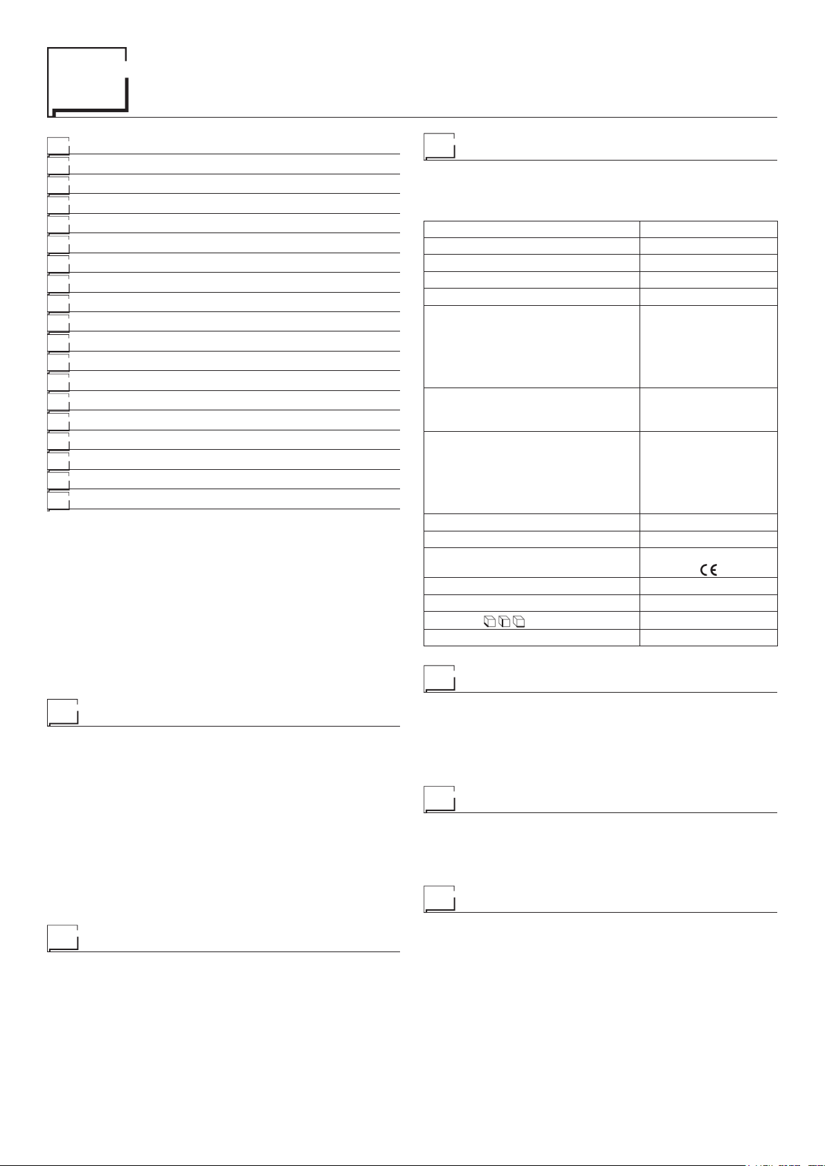
Technical data
The general technical data of the system are summarized in table 1.
Table 1
Model DIX WF 793.M
Input voltage of wire feeder V 24 DC
Power output of feeder motor W 100
N° of drive rolls 4
Rated wire feeding speed m/min 0,6 ÷ 25
• Carbon steel
• Stainless steel
Compatible wire types
Spool
Diameter
Weight
Protection gas
Duty cycle at 60% A 600
Duty cycle at 100% A 460
Standards
Insulation class F
Protection class IP 23 S
Dimensions
Weight kg 15
• Aluminium magnesium
• Aluminium silicon
• Basic and rutile cored
wires
Ømm
kg
• Carbon dioxide
• Pure Argon
• Argon-Carbon dioxide-
Oxygen
• Argon and Carbon dioxide
blends
mm 635 - 415 - 270
300
20 (max)
IEC 60974-5
Introduction
Thank you for buying our product.
In order to get the best performance out of the plant and ensure the
maximum lifespan of its parts, the use and maintenance instructions contained in this manual must be read and strictly complied
with, as well as the safety instructions contained in the rele-
vant folder. If repairs to the plant are required, we recommend that
our clients contact our service centre workshops, as they have the
necessary equipment and personnel that are specifically trained
and constantly updated.
All our machines and equipment are constantly developed and so
changes may be made in terms of their construction and features.
IMPORTANT: T he wire feeder must only be used together with the
welding power source and not for any other use.
Description
Professional large diameter 4-roller wire feeder that guarantees
precise and constant feeding of the wire. This wire feeder’s principal characteristics are:
• Designed for use with all types of solid and core type wire.
• A 24 V direct current ratio motor, fitted with an encoder.
• A gas solenoid valve.
• Wire speed (welding current) and welding voltage adjustment.
• Gas and wire feed test.
Graduated knobs for precise adjustment of the wire pressure
•
that stays unvaried when the arms open and close.
The wire feeder rollers can be replaced without using any tools.
•
How to lift up the system
The wire feeder is fitted with a strong handle, built into the frame,
which is only used to facilitate lifting and carrying it.
NOTE: The lifting and transporting devices conform with European regulations. Do not use other equipment to lift or transport the
wire feeder.
Opening the packaging
When receiving the wire feeder remove it and all its accessories /
components from the relevant packing, and check that they are in
good condition. If not, report the situation to the dealer immediately .
Installation and connections
CONNECTION OF THE INTERCONNECTING CABLE
BETWEEN WIRE FEEDER AND WELDING POWER
SOURCE
The extension between the welding power source and wire feeder consists of a power cable, a multipolar cable for auxiliary power supply and a gas hose which are to be connected to the rear
of the wire feeder.
The gas tube must be connected to the quickfit connector
•
(Pos. 5, Fig. A).
•
The power cable must be fixed to the quick-fit connector (Pos. 7,
Fig. A).
•
The auxiliary cable must be fixed to the special connector
(Pos. 6, Fig. A).
2
The connecting cable also includes the feed (blue) and return (red)
pipes for the water that are used for cooling the welding equipment’s torch that must be connected to the respective (blue and
red) rapid couplings on the back of the wire feeder (Pos. 3, Fig. A).
Once this task has been completed, do not forget to secure the
connecting cable to the base, using the special little strap provided.
CONNECTING THE TORCH
Screw the torch onto the centralised connection on the front panel
of the wire feeder (pos. 4, Fig. A) and connect the feed (blue) and
return (red) water hoses for cooling the torch head to the respective (blue and red) rapid couplings on the front panel of the wire
feeder (Pos. 3, Fig. A).
Loading wire
•
Insert the spool (Ø 300 mm max.) onto its support so that the
wire unwinds anticlockwise and centre up the protruding reference point on the support with the respective opening in the
spool.
Thread the end of the wire into the back guide (Pos. 1, Fig. B)
•
on the drawing mechanism.
Lift up the idle rolls (Pos. 4, Fig. B) releasing the roll pressure
•
device (Pos. 2, Fig. B). Make sure that the drive rolls (Pos. 7,
Fig. B) have the diameter corresponding to the wire being used
stamped on the outside.
• Insert the wire into the central wire guide and the wire guide on
the centralised connection (Pos. 5, Fig. B) by a few centimetres.
Lower the idle roller holder arms, making sure that the wire slots
into the hollow in the motor’s roller. If necessary , adjust the pres sure between the rollers by turning the relevant screw (Pos. 2,
Fig. B). The correct pressure is the minimum that does not allow
the rollers to skid on the wire. Excessive pressure will case deformation of the wire and tangling on the entrance of the sheath;
insufficient pressure can cause irregular welding.
Assembly of drive rolls
Unscrew the two screws (Pos. 6, Fig. B). Lift up the idle rollholder
arm (Pos. 3, Fig. B) and proceed as follows:
• Each roller shows the type of wire and diameter on the two external sides.
Install the right rolls (Pos. 7, Fig. B) making sure the groove is
•
in the correct position for the diameter of the wire being used.
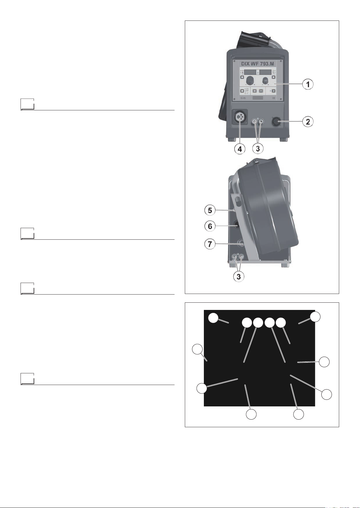
Command and control units (Fig. A)
Pos. 1 Control panel.
Pos. 2
Pos. 3 Rapid couplings for cooling MIG-MAG welding torch.
Pos. 4 Centralized torch connection.
Pos. 5 Rapid coupling for connecting the gas hose.
Pos. 6 14-pole connector the interconnecting cable connec-
Pos. 7
WARNING: For information on the wire feeder’s control panel, read the manual carefully , of the welding
power source connected to it.
17-pole connector for remote control connections.
tions.
Fast coupling reverse polarity.
Before welding
•
Before welding, check that the data on the welding power source
plate correspond to the supply voltage and frequency.
Make sure that the wire feeder is correctly connected to the pow-
•
er source through the interconnecting cable and that the ground
cable is connected to the piece to be welded.
Preset the adjustments using the encoders on the control panel.
•
FIG. A
1
6
FIG. B
2
3 4 4 3
2
5
6
77
3
 Loading...