

DINSE DIX PI GO 2006.M, DIX PI GO 2006.M Puls Operation Manual

BA-0114
Operations manual
Welding Power Source
DIX PI GO 2006.M
DIX PI GO 2006.M Puls
Keep in secure area for future reference!
SCHWEISSEN WELDING
WELDINGSCHWEISSEN SCHWEISSEN

Introduction 2
Description 2
Operating features 2
Technical data 3
Usage limits (IEC 60974-1) 3
How to lift up the system 4
Opening the packaging 4
Installation and connections 4
Connection to the electrical supply 4
Loading wire 5
Assembly of drive rollers 5
Control welding power source 5
MIG/MAG / Puls MIG / DOUBLE Puls MIG
welding with GAS 6
MIG/MAG / Puls MIG / DOUBLE Puls MIG
welding without GAS 7
Spot welding 8
Interval welding (Stitch) 8
Aluminium welding 8
Electrode welding (MMA) 8
TIG welding with “Lift” 9
Maintenance 10
Optional 10
The pointing out of any difficulties and their
elimination 10
Replacing the digital interface PCB 10
Troubleshooting table 1 1
Meaning of graphic symbols on welding power
source 12
Wiring diagram 12
DINSE G.m.b.H.
Tarpen36 • D-22419 Hamburg
Tel. +49 (0)40 658 75-0
Fax +49 (0)40 658 75-200
info@dinse.eu – www.dinse.eu
Copyright © 2018 DINSE G.m.b.H., Hamburg.
These instructions or excerpts there of shall not be duplicated, translated or reproduced, nor shall they be stored, processed, transmitted or
distributed by any electronic means without the prior written permission
of DINSE G.m.b.H.
Introduction
Thank you for buying our product.
In order to get the best performance out of the plant and ensure
the maximum lifespan of its parts, the use and maintenance
instructions contained in this manual must be read and strictly
complied with, as well as the safety instructions contained
in the relevant folder. If repairs to the plant are required, we
recommend that our clients contact our service centre workshops, as they have the necessary welding power source and
personnel that are specifically trained and constantly updated.
All our welding power sources and welding power source are
constantly developed and so changes may be made in terms
of their construction and features.
Description
MUL TI-FUNCTION INVERTER WELDING POWER SOURCE
FOR MIG/MAG, MMA, and TIG WELDING
The DIX PI GO 2006.M / DIX PI GO 2006.M Puls series of mul-
ti-function welding power sources are characterised by cutting
edge, attractive design combined with latest generation inverter technology and digital welding control. Innovative, technologically advanced, robust, and easy to use, they can be used
for very high quality MIG/MAG and Puls MIG welding for all
materials and especially stainless steel and aluminium, reducing repeat work due to spray to a minimum, using electrodes,
and in TIG with “Lift” type ignition, and they represent the best
solution for all industrial fields and all specialist welding purposes that call for high precision and repeatable results. The
DIX PI GO 2006.M / DIX PI GO 2006.M Puls welding power
sources, fitted with the extraordinary DIX-ARC meet the needs
of those that wish to combine synergy with complete control of
all welding parameters.
These are systems open to the future evolution of technology the control software can be kept up to date with the latest versions with the help of a personal computer.
Operating features
The main feature of the welding units are:
• Metallic main structure with shockproof plastic front frame.
• Controls protected by a visor.
Exceptional characteristics for MIG/MAG, MMA, and TIG
•
welding with “Lift” type ignition.
Synergic digital control of all welding parameters, with the
•
following functions:
-
Allows less expert operators to regulate all welding parameters in a user-friendly way and extremely easily, choosing the type of program on the basis of the material, wire
diameter, and gas used.
-
Innovative “DIX ARC” software for controlling all welding
parameters.
- BURN BACK control. At the end of each weld, in any condition and with any material, the digital control ensures a
perfect wire cut, prevents the typical “wire globule” from
forming and ensures correct arc restriking.
-
WSC Wire start control. This arc striking control device prevents wire from sticking to the workpiece or torch nozzle
and ensures precise and smooth arc striking, particularly
when welding aluminium.
-
Welding parameters that are controlled digitally by a microprocessor, are monitored and modified in just a few seconds, maintaining a consistently precise and stable arc as
the welding conditions continue to vary due to the movement of the torch and the irregularities of the parts to be
welded.
2

- The SWS “Smart Welding Stop” system at the end of TIG
welding. Lifting up the torch without switching off the arc will
introduce a slope down and it will switch off automatically .
-
“Energy Saving” function to operate the power source cooling fan and the torch water cooling only when necessary .
• High electrical performance resulting in a reduction in energy consumption.
Professional large diameter 4-roller wire feeder that guaran-
•
tees precise and constant feeding of the wire. This wire feeder’s principal characteristics are:
-
Designed for use with all types of solid and core type wire.
- A 24 V direct current ratio motor.
- A gas solenoid valve.
- Wire speed (welding current) and welding voltage adjustment.
- Graduated knobs for precise adjustment of the wire pressure that stays unvaried when the arms open and close.
-
The feeder rollers can be replaced without using any tools.
Technical data
The general technical data of the system are summarized in
table 1.
Usage limits (IEC 60974-1)
The use of a welding power source is typically discontinuous,
in that it is made up of effective work periods (welding) and rest
periods (for the positioning of parts, the replacement of wire
and underflushing operations etc. This welding power source
is dimensioned to supply a I2 max nominal current in complete
safety for a period of work of 35% of the total usage time. The
regulations in force establish the total usage time to be 10 minutes. The work cycle is considered to be 35% of this period
of time. Exceeding the work cycle allowed could cause a trip
switch to trip (for further information see the control panel manual), which protects the components inside the welding power
source against dangerous overheating. After several minutes
the overheat cut-off rearms automatically and the welding power source is ready for use again.
T able 1
Model
Three-phase input 50/60 Hz V 400 ± 15%
Mains supply: Z
Power input (I
Delayed fuse (I
Power factor / cosφ 0,74 / 0,99 0,69 / 0,99 0,77 / 0,99
Efficiency degree η 0,89 0,86 0,9
Voltage without load V 60
Current range A 10 ÷ 250
Welding current @ 100% duty cycle (40°C) A 180
Welding current @ 60% duty cycle (40°C) A 200
Welding current @ 35% duty cycle (40°C) A 250
Wires diameter mm 0,6 - 1,2 - -
Welding wire spool
Diameter / Weight mm / kg 300 / 15 - -
N° drive rolls 4 - -
Power output of feeder motor W 55 - -
Rated wire feeding speed m/min 0,5 ÷ 22 - -
Ø MMA electrodes mm - - 1,6 - 4,0
Ø TIG electrodes mm - 1,0 - 3,2 -
Shield gas
Standards
Protection class IP 23 S
Insulation class H
Dimensions
Weight kg 21
(*) Mains supply Z
WARNING: This welding power source does not comply with EN/IEC 61000-3-12. If it is connected to a public low voltage system, it is the re-
sponsibility of the installer or user of the welding power source to ensure, by consultation with the distribution network operator if necessary , that
the welding power source may be connected.
(*) Ω 0,037
max
Max) kVA 10 8,5 11
2
eff) A 16 10 16
mm 650 - 388 - 300
: maximum impedance value allowed for the grid according to the EN/IEC 61000-3-11 standard.
max
MIG/MAG TIG MMA
•Carbon dioxide
•Pure Argon
•Argon - Carbon dioxide
- Oxygen
•Argon and Carbon
dioxide blends
DIX PI GO 2006.M / DIX PI GO 2006.M Puls
- -
IEC 60974-1 - IEC 60974-5 - IEC 60974-10 -
3

How to lift up the system
Strap the system safely and securely in the slings working from
the bottom, then lift up from the ground.
This welding power source has a robust handle built into the
frame for moving the welding power source.
NOTE: These hoisting and transportation devices conform to
European standards. Do not use other hoisting and transportation systems.
Opening the packaging
Perform the following operations on receiving the welding power source:
• Remove the welding power source and all accessories and
components from the packaging.
Check that the welding power source is in good condition;
•
otherwise immediately inform the retailer or distributor.
• Check that all the ventilation grilles are open and that there
is nothing to obstruct the correct air flow.
Installation and connections
The installation site for the system must be carefully chosen
in order to ensure its satisfactory and safe use. The user is responsible for the installation and use of the system in accordance with the producer’s instructions contained in this manual.
Before installing the system the user must take into consideration the potential electromagnetic problems in the work area.
In particular, we suggest that you should avoid installing the
system close to:
• Signalling, control and telephone cables.
• Radio and television transmitters and receivers.
• Computers and control and measurement instruments.
• Security and protection instruments.
Persons fitted with pace-makers, hearing aids and similar welding power source must consult their doctor before going near a
welding power source in operation. The welding power source’s
installation environment must comply to the protection level of
the frame.
The welding unit is characterized by the following classes:
IP 23 S protection class indicates that the welding power
•
source can be used in both interior and exterior environments.
•
The “S” usage class indicates that the welding power source
can be employed in environments with a high risk of electri-
cal shocks.
This system is cooled by means of the forced circulation of air,
and must therefore be placed in such a way that the air may
be easily sucked in and expelled through the apertures made
in the frame.
Assemble the system in the following way:
• Assemble the trolley .
• Fixing the cooling unit to the trolley .
Fixing of the welding power source to the trolley and the cool-
•
ing unit (electrical and plumbing connections).
• Connect up the welding power source to the mains.
Connect up the wire-feeder/generator interconnection cable.
•
• Connect up the welding cables.
Instructions for fitting the individual components / optional extras are contained in the relevant packaging.
Connection to the electrical supply
Connection of the welding power source to the user line
(electrical current) must be performed by qualified personnel.
Before connecting the welding power source to the mains
power supply, make sure that rated voltage and frequency correspond to those provided by the mains power supply and that the welding power source’s power switch is
turned to “O”.
Use the welding power source’s own plug to connect it up to
the main power supply. Proceed as follows if you have to replace the plug:
3 conducting wires are needed for connecting the welding
•
power source to the supply .
The fourth, which is YELLOW GREEN in colour is used for
•
making the “GROUND” connection.
Before connecting the welding power source to the mains
power supply, make sure that rated voltage and frequency correspond to those provided by the mains power supply and that the welding power source’s power switch is
turned to “O”.
Table 2 shows the capacity values that are recommended for
fuses in the line with delays.
NOTE: Any extensions to the power cable must be of a suitable diameter, and absolutely not of a smaller diameter than the
special cable supplied with the welding power source.
Model
Power input (I
Delayed fuse (I
Duty cycle @ 35% (40°C) A 250
Mains cable
Length
Section
Ground cable
Length
Section
Max) kVA 10 8,5 11
2
eff) A 16 10 16
m
2
mm
m
2
mm
MIG/MAG TIG MMA
DIX PI GO 2006.M / DIX PI GO 2006.M Puls
4
2,5
3 - 4
35
4
T able 2
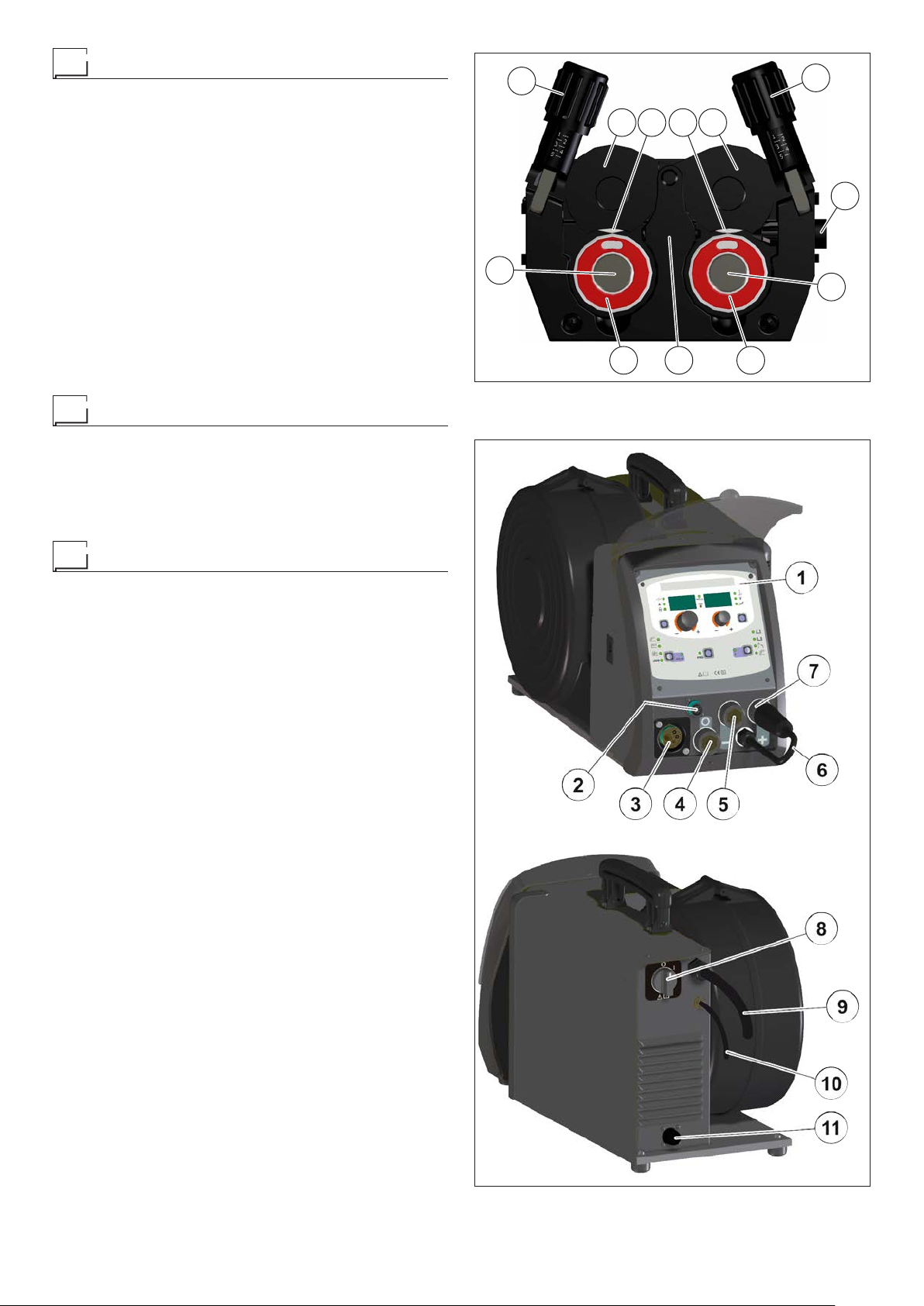
Loading wire
•
Fit the reel (diam. 300 mm) on the support so that the wire
unrolls clockwise, and center the projecting reference on the
support with the relative hold on the reel.
Thread the end of the wire into the back guide (Pos. 1, Fig. A)
•
on the drawing mechanism.
Lift up the idle rolls (Pos. 4, Fig. A) releasing the roll pres-
•
sure device (Pos. 2, Fig. A). Make sure that the drive rolls
(Pos. 7, Fig. A) have the diameter corresponding to the wire
being used stamped on the outside.
• Insert the wire into the central wire guide and the wire guide
on the centralised connection (Pos. 5, Fig. A) by a few centimetres. Lower the idle roller holder arms, making sure that
the wire slots into the hollow in the motor’s roller. If necessary, adjust the pressure between the rollers by turning the
relevant screw (Pos. 2, Fig. A). The correct pressure is the
minimum that does not allow the rollers to skid on the wire.
Excessive pressure will case deformation of the wire and tangling on the entrance of the sheath; insufficient pressure can
cause irregular welding.
Assembly of drive rollers
Unscrew the two screws (Pos. 6, Fig. A). Lift up the idle rollholder arm (Pos. 3, Fig. A) and proceed as follows:
•
Each roller shows the type of wire and diameter on the two
external sides.
Install the right rolls (Pos. 7, Fig. A) making sure the groove is
•
in the correct position for the diameter of the wire being used.
2
6
FIG. A
3 4 4 3
5
2
1
6
77
Control welding power source
Fig. B
Pos. 1 control panel.
Pos. 2 Up/Down connector.
Pos. 3 Centralized torch connection.
Pos. 4 Rapid coupling neutral position, used only for MMA
and TIG electrode welding.
Fast coupling positive polarity .
Pos. 5
Pos. 6 Cable to change polarity .
Pos. 7 Fast coupling negative polarity .
Pos. 8 Power supply switch. In the “O” position the welding
power source is off.
Mains cable.
Pos. 9
Pos. 10 Gas hose.
Pos. 11 Connector for connecting the cooling system.
5
FIG. B
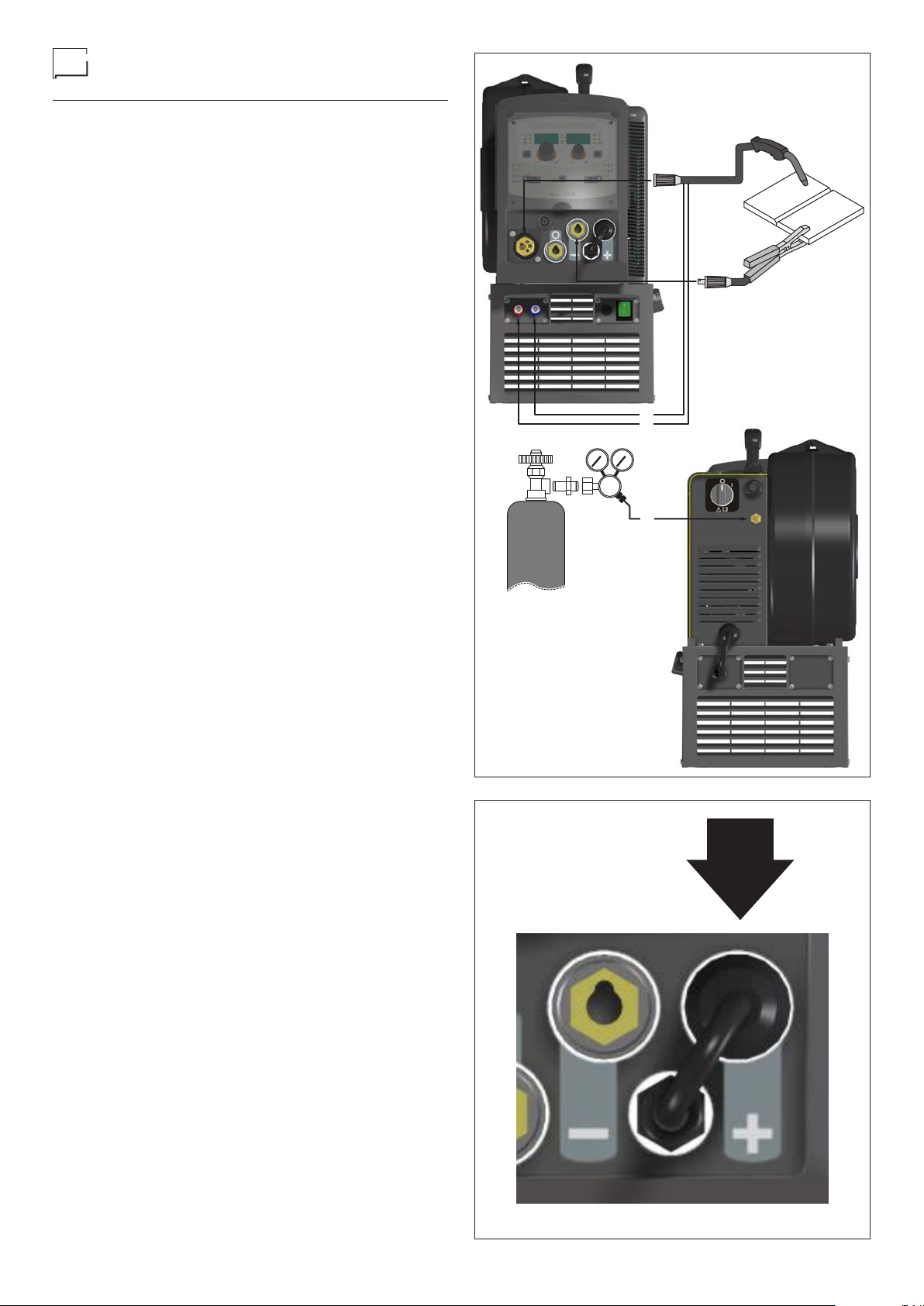
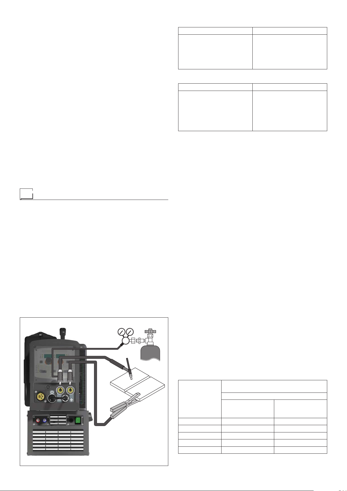
MIG/MAG / Puls MIG / DOUBLE Puls
MIG welding with SHIELD GAS
To begin MIG/MAG / Puls MIG / DOUBLE Puls MIG welding,
carry out the following tasks (with the welding power source
switched off).
1 - Connecting the cables (Fig. C1)
1) Connect the gas hose to the pressure reducer fitted on
the cylinder beforehand. Gas cylinders are supplied with
a pressure reducer to adjust pressure of the gas used for
welding.
2) Screw the torch to the centralised connection on the front
panel of the welding power source (Pos. 3, Fig. A).
3) Connect up the earthing system cable to the rapid cou-
pling marked by a - (negative) symbol and then the relevant ground clamps to the piece being welded or to its
support in an area free from rust, paint and grease. Using
particularly long earthing cables reduces the voltage and
causes some problems from increased resistance and inductance of the cables that could cause faulty welding. Follow instructions to avoid these problems:
Use earthing and extension cables with appropriate sec-
•
tion.
• Lay out the cables as a flat as possible to prevent them
from coiling up.
4) Connect the reverse polarity cable to the positive terminal
(Fig. C2).
BLUE
RED
2 - Welding
1) Switch the welding power source on by moving the power
supply switch to I (Pos. 6, Fig. B).
2) Make the adjustments and do the parameter settings on the
control panel (for further information see the control panel
manual).
3) Load the wire using the torch button, after having removed
the wire guide nozzle from the torch to allow the wire to
come out freely, while loading (remember that the wire
guide nozzle must correspond to the diameter of the wire
used).
4) Open the tap on the cylinder slowly and adjust the reducer
knob to obtain a pressure of about 1,3 to 1,7 bar, and regulate the flow to a value between 14 and 20 lit/min to suit
the current used for welding.
5) The welding power source is ready to weld. Start welding
by moving close to the welding point and press the torch
button.
6) Once welding has been completed remove any slag, switch
off the welding power source (which is only to be done
when the fan is not running), and close the gas cylinder.
BLACK
FIG. C1
6
FIG. C2
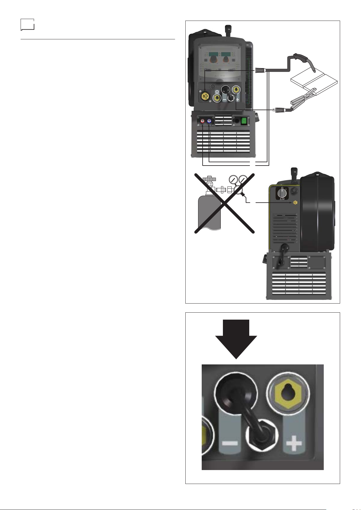
MIG/MAG / Puls MIG / DOUBLE Puls
MIG welding without SHIELD GAS
To begin MIG/MAG / Puls MIG / DOUBLE Puls MIG welding,
carry out the following tasks (with the welding power source
switched off).
1 - Connecting the cables (Fig. D1)
1) Screw the torch to the centralised connection on the front
panel of the welding power source (Pos. 3, Fig. A).
2) Connect up the earthing system cable to the rapid coupling marked by a + (positive) symbol and then the relevant
ground clamps to the piece being welded or to its support in
an area free from rust, paint and grease. Using particularly
long earthing cables reduces the voltage and causes some
problems from increased resistance and inductance of the
cables that could cause faulty welding. Follow instructions
to avoid these problems:
Use earthing and extension cables with appropriate sec-
•
tion.
• Lay out the cables as a flat as possible to prevent them
from coiling up.
3) Connect the reverse polarity cable to the negative terminal
(Fig. D2).
2 - Welding
1) Switch the welding power source on by moving the power
supply switch to I (Pos. 6, Fig. B).
2) Make the adjustments and do the parameter settings on the
control panel (for further information see the control panel
manual).
3) Load the wire using the torch button, after having removed
the wire guide nozzle from the torch to allow the wire to
come out freely, while loading (remember that the wire
guide nozzle must correspond to the diameter of the wire
used).
4) Open the tap on the cylinder slowly and adjust the reducer
knob to obtain a pressure of about 1,3 to 1,7 bar, and regulate the flow to a value between 14 and 20 lit/min to suit
the current used for welding.
5) The welding power source is ready to weld. Start welding
by moving close to the welding point and press the torch
button.
6) Once welding has been completed remove any slag, switch
off the welding power source (which is only to be done
when the fan is not running), and close the gas cylinder.
FIG. D1
BLUE
BLACK
RED
7
FIG. D2
Spot welding
Electrode welding (MMA)
Welding can be done with or without gas. The substantial difference with MIG/MAG welding is essentially related to the torch
and the adjustments that must be made on the control panel.
• Depending on the torch chosen and the work to be done, a
gas guide nozzle can be fitted on the torch that is specifically for spot welding (see Fig. E).
• Use the control panel to select the spot-welding mode and,
if necessary , make the changes to the related “Special functions - Fx” (for further information see the control panel manual), which allows the welding power source to do this specific
type of welding.
To begin spot welding:
Place the gas guiding nozzle perpendicular on the workpiece
•
to be spot welded.
Press the torch button to start the welding current and wire
•
feed.
When the spot welding time expires (SPOT WELD TIME),
•
the wire feed stops automatically .
When the torch button is pushed again a new welding cy-
•
cle starts.
• Release the torch button.
FIG. E
Interval welding (Stitch)
The substantial differences with the spot welding mainly concern the adjustments that must be carried on the welding power source.
Use the control panel to select the interval welding mode and
then make the changes to the related “Special functions - Fx”
(for further information see the control panel manual), which
allows the welding power source to do this specific type of
welding.
To begin interval welding:
Press the torch button to start the welding current and wire
•
feed.
• At this point the welding power source automatically carries
out a succession of welded portions (STITCH WELD TIME)
followed by a pause (STITCH WELD P AUSE), according to
the times entered previously . This procedure stops automatically only when the TORCH BUTTON is released.
When the torch button is pushed again the torch begins a
•
new interval welding cycle.
On the DIX PI GO 2006.M / DIX PI GO 2006.M Puls welding
power source, electrode welding is used to weld most metals
(different types of steel, etc.) using coated rutilic and basic electrodes with diameters ranging from Ø 1.6 mm to Ø 6 mm, and
devices that the user can adjust for “Arc Force”, “Hot Start”, and
Anti-sticking functions to avoid the electrodes sticking.
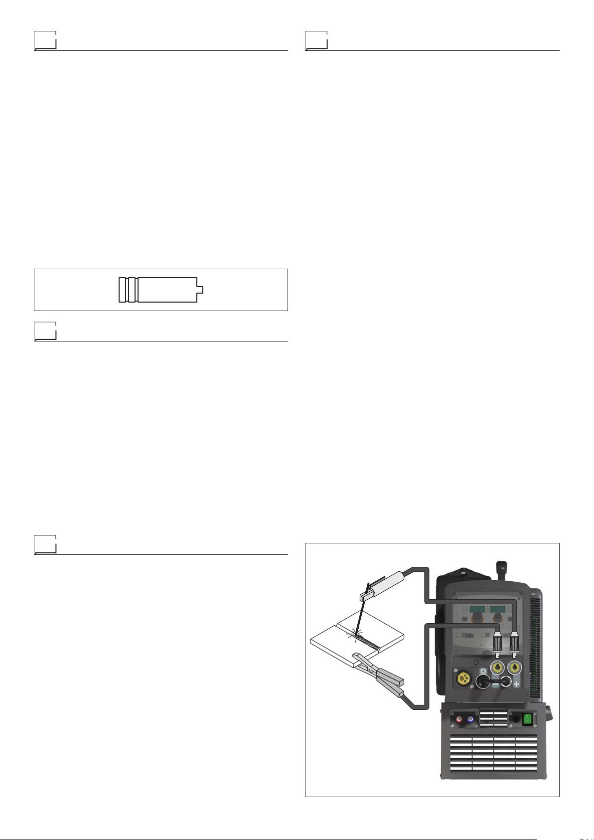
1) Connecting the welding cables (Fig. F):
Disconnect the welding power source from the mains power
supply and connect the welding cables to the output terminals (Positive and Negative) of the welding power source,
attaching them to the clamp and ground with the polarity
specified for the type of electrode being used (Fig.F). Always follow the electrode manufacturer’s instructions. The
welding cables must be as short as possible, they must be
near to one another, positioned at or near floor level. Do
not touch the electrode clamp and the ground clamp simultaneously.
2) Switch the welding power source on by moving the power
supply switch to I (Pos. 8, Fig. B).
3) Make the adjustments and do the parameter settings on the
control panel (for further information see the control panel
manual).
4) Carry out welding by moving the torch to the workpiece.
Strike the arc (press the electrode quickly against the metal and then lift it) to melt the electrode, the coating of which
forms a protective residue. Then continue welding at an inclination of about 60° compared with the metal in relation
to the direction of welding.
P ART T O BE WELDED
The part to be welded must always be connected to ground
in order to reduce electromagnetic emission. Much attention
must be afforded so that the ground connection of the part to be
welded does not increase the risk of accident to the user or the
risk of damage to other electric welding power source. When
it is necessary to connect the part to be welded to ground, you
should make a direct connection between the part and the
ground shaft. In those countries in which such a connection
is not allowed, connect the part to be welded to ground using
suitable capacitors, in compliance with the national regulations.
Aluminium welding
To weld with aluminium wire proceed as follows:
• Replace the drive rolls with special ones for aluminium wire.
We recommend to use a torch set with a maximum lenght of
•
3 m and a capillary liner, e.g. DIX DSK 2-xx.
Set the pressure between the drive rollers at the minimum,
•
by turning the screw provided.
Use argon gas at a pressure of 1,3 - 1,7 bar and regulate
•
the flow to a value between 14 and 20 lit/min to suit the current used for welding.
FIG. F
8
WELDING P ARAMETERS
T able 3 shows some general indications for the choice of elec trode, based on the thickness of the parts to be welded. The
values of current to use are shown in the table with the respective electrodes for the welding of common steels and low-grade
alloys. These data have no absolute value and are indicative
data only . For a precise choice follow the instructions provided
by the electrode manufacturer.
The current to be used depends on the welding positions and
the type of joint, and it increases according to the thickness and
dimensions of the part.
The current intensity to be used for the different types of welding, within the field of regulation shown in table 4 is:
• High for plane, frontal plane and vertical upwards welding.
• Medium for overhead welding.
Low for vertical downwards welding and for joining small pre-
•
heated pieces.
A fairly approximate indication of the average current to use in
the welding of electrodes for ordinary steel is given by the following formula:
I = 50 × (Øe - 1)
Where:
I = intensity of the welding current
Øe = electrode diameter
Example:
For electrode diameter 4 mm
I = 50 × (4 - 1) = 50 × 3 = 150 A
TIG welding with “Lift”
In the TIG process welding is achieved by melting the two metal pieces to be joined, with the possible addition of material
from the outside, using an arc ignited by a tungsten electrode.
The “Lift” type ignition used in DIX PI GO 2006.M / DIX PI GO
2006.M Puls welding power sources makes it possible to re-
duce tungsten inclusions on ignition to a minimum. The molten
bath and the electrode are protected by and inert gas (for example, Argon). This type of welding is used to weld thin sheet
metal or when elevated quality is required.
1) Connecting the welding cables (Fig. G):
•
Connect one end of the gas hose to the gas connecter on
the TIG torch and the other end to the pressure reducer
on the inert gas cylinder (Argon or similar).
T able 3
Welding thickness (mm) Ø electrode (mm)
1,2 ÷ 2
1,5 ÷ 3
3 ÷ 5
5 ÷ 12
≥12
≥20
1,6
2
2,5
3,25
4
≥5
T able 4
Ø electrode (mm) Current (A)
1,6
2
2,5
3,2
4
5
6
30 ÷ 60
40 ÷ 75
60 ÷ 110
95 ÷ 140
140 ÷ 190
190 ÷ 240
220 ÷ 330
• With the welding power source switched off:
-
Connect the ground cable to the snap-on connector
marked + (positive).
-
Connect the relative ground clamp to the workpiece or
to the workpiece support in an area free of rust, paint,
grease, etc..
-
Connect the TIG torch power cable to the snap-on connector marked - (negative).
2) Switch the welding power source on by moving the power
supply switch to I (Pos. 8, Fig. B).
3) Make the adjustments and do the parameter settings on the
control panel (for further information see the control panel
manual).
4) Open the gas cylinder and regulate the flow by adjusting
the valve on the TIG torch by hand.
5) Ignite the electric arc by contact, using a decisive, quick
movement without dragging the tungsten electrode on the
piece to be welded (“Lift” type ignition).
6) The welding power source has a SWS “Smart Welding
Stop” system for the end of TIG welding. Lifting up the torch
without switching off the arc will introduce a slope down and
it will switch off automatically.
7) When you have finished welding remember to shut the
valve on the gas cylinder.
Table 5 shows the currents to use with the respective electrodes for TIG DC welding. This input is not absolute but is for
your guidance only; read the electrode manufacturers’ instructions for a specific choice. The diameter of the electrode to use
is directly proportional to the current being used for welding.
FIG. G
Ø ELECTRODE
9
ELECTRODE TYPE
Current adjustment field (A)
(mm)
1 10-50 10-50
1,6 50-80 50-80
2,4 80-150 80-150
3,2 150-250 150-250
4 200-400 200-400
Tungsten
Ce 1%
Grey
TIG DC
Tungsten
Rare ground 2%
Turchoise
T able 5

Maintenance
ATTENTION: Cut off the power supply to the welding power
source before effecting any internal inspection.
DIX PI GO 2006.M / DIX PI GO 2006.M Puls
IMPORTANT: For fully electronic welding power sources, re-
moving the dust by sucking it into the welding power source by
the fans, is of utmost importance.
In order to achieve correct functioning of the welding power
source, proceed as described:
Periodic removal of accumulations of dirt and dust inside the
•
welding power source using compressed air. Do not point
the jet of air directly at the electrical parts as this could damage them.
Periodical inspection for worn cables or loose connections
•
that could cause overheating.
The pointing out of any difficulties
and their elimination
The supply line is attributed with the cause of the most common difficulties. In the case of breakdown, proceed as follows:
1) Check the value of the supply voltage.
2) Check that the power cable is perfectly connected to the
plug and the supply switch.
3) Check that the power fuses are not burned out or loose.
4) Check whether the following are defective:
• The switch that supplies the welding power source
• The plug socket in the wall
• The mains switch
NOTE: Given the required technical skills necessary for the
repair of the welding power source, in case of breakdown we
advise you to contact skilled personnel or our technical service department.
TORCH
The torch is subjected to high temperatures and is also stressed
by traction and torsion. We recommend not to twist the wire
and not to use the torch to pull the welding power source. As
a result of the above the torch will require frequent maintenance such as:
• Cleaning welding splashes from the gas diffuser so that the
gas flows freely .
• Substitution of the contact point when the hole is deformed.
Cleaning of the wire guide liner using trichloroethylene or
•
specific solvents.
• Check of the insulation and connections of the power cable;
the connections must be in good electrical and mechanical
condition.
SP ARE PARTS
Original spares have been specifically designed for our welding power source. The use of spares that are not original may
cause variations in the performance and reduce the safety level of the welding power source. We are not liable for damage
due to use of spare parts that are not original.
Optional
AIR AND/OR WATER COOLED UP/DOWN TORCH
This command and works as an alternative:
• To the ENCODER - SX knob on the welding power source’s
control panel. In “synergic” MIG MAG and “manual” MIG
MAG welding processes, by pressing the two right (+) and
left (-) buttons you can regulate the values for the synergic
welding parameters.
• To the ENCODER - DX knob on the welding power source’s
control panel. In the JOB welding process, by pressing the
two right (+) and left (-) buttons you can scroll the welding
points set previously .
Replacing the digital interface PCB
Proceed as follows:
• Unscrew the 4 screws fastening the front rack panel.
• Remove both the adjustment knobs.
• Extract wiring connectors from the digital interface PCB.
• Unscrew the nuts and washers on the support.
Remove the digital interface PCB by lifting it out of its sup-
•
ports.
Proceed vice versa to assemble the new digital interface
•
PCB.
10

Troubleshooting table
WARNING: Any internal inspections or repairs are only to be done by qualified personnel!
IMPORTANT: Remember to disconnect the mains power supply and wait for the internal capacitors to discharge (about 2 min-
utes) before starting to check and repair the welding power source if necessary .
Defect Solution
The welding power source
does not switch on, control
panel switched off.
Line fuses fused
“instantaneously”.
Line fuses fused after
a work period.
Welding power source on,
control panel on, fan stopped.
Welding power source
on, display does not
show correct values.
No gas coming out of the torch. • Check and if necessary replace the solenoid valve or gas hose.
The wire feed motor does not
work during MIG/MAG welding.
Welding current insufficient
or not constant.
Arc ignition difficult, the arc
switches off immediately
after ignition during MIG/
MAG welding.
The wire sticks to the
workpiece to be welded.
• Check that the welding power source is installed correctly and that the
mains supply has sufficient power to supply the welding power source.
• Check the switch, cable and plug on the power supply line and replace them if necessary .
• Check, and if necessary replace, the digital interface PCB or the control PCB.
• Check that the welding power source is installed correctly .
• Check and if necessary replace the motor, transformer, or rectifier .
• Check that you have fitted line fuses of adequate absorption capacity .
• Check the wiring that powers the fans.
• Check that there are no mechanical impediments blocking the fans.
• Check and if necessary replace the digital interface PCB.
• See the error codes and signals shown in the manual for the control panel.
• Check the wiring that powers the various boards.
• Check, and if necessary replace, the digital interface PCB or the control PCB.
• Check the wiring that powers the gas solenoid valve.
• Check, and if necessary replace, the digital interface PCB or the control PCB.
• Check the wiring that powers the wire feed motor.
• Check that there are no mechanical impediments blocking the motor.
• Check that the motor is working correctly and if necessary replace it.
• Check and if necessary replace the digital interface PCB.
• Check the power supply line.
• Check and if necessary replace the wires (section or length inadequate).
• Check the line voltage using a voltmeter.
• Use the control panel manual to make sure you have set
the various welding parameters correctly .
• Check compatibility of the torch and the wire used.
• Check that the torch and all its components are working correctly
and replace them if necessary (e.g. worn components).
• Check and if necessary replace the digital interface PCB.
• Check that there are no mechanical impediments blocking correct unwinding of the wire.
• Check that the motor is working correctly and if necessary replace it.
• Check and if necessary replace the digital interface PCB.
11
 Loading...