

Dino-Power Titan 440i Operation Manual
Operation manual for Airless paint
sprayer
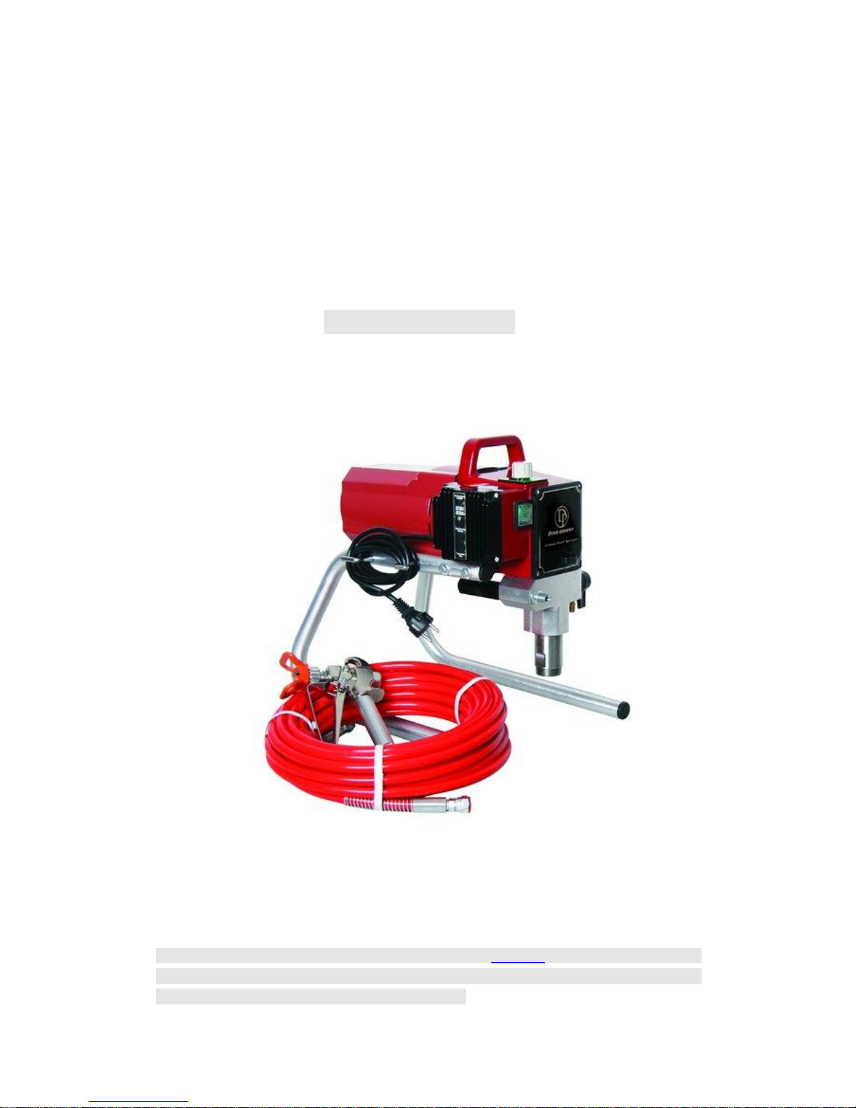
High Pressure Electric Airless paint sprayer Titan 440i model
intelligent series
Remark: this guide manual is the same with model DP-6389 ,the content include :the
operation of equipment,cleaning ,maintenance ,and repair,be sure to pre-operational ,read
the manual carefully before you use this machine.

2
1. warning and precautions
Safety Precautions
This manual contains information that must be read and understood before using
the airless sprayer equipment. When you come to an area that has one of the following
symbols, pay particular attention and make certain to heed the safeguard.
WARNING
This symbol indicates a potential hazard that may cause serious injury or loss of life.
Important safety information will follow.
CAUTION
This symbol indicates a potential hazard to you or to the equipment. Important information
that tells how to prevent
damage to the equipment or how to avoid causes of minor injuries will follow.
NOTE: Notes give important information which should be given special attention.
WARNING
HAZARD: Injection injury – A high pressure fluid stream produced by this equipment can
pierce the
skin and underlying tissues, leading to serious injury and possible amputation. See a
physician immediately.
DO NOT TREAT AN INJECTION INJURY AS A SIMPLE CUT! Injection can lead to
amputation. See a physician immediately.
The maximum operating range of the sprayer is 3200 PSI/221BAR fluid pressure.
PREVENTION:
• NEVER aim the airless spray gun at any part of the body.
• NEVER allow any part of the body to touch the fluid stream. DO NOT allow body to touch
a leak in the fluid hose.
• NEVER put hand in front of the gun. Gloves will not provide protection against an
injection injury.
• ALWAYS lock gun trigger, shut pump off, and release all pressure before servicing,
cleaning tip or guard, changing
tip, or leaving unattended. Pressure will not be released by turning off the motor. The
PRIME/SPRAY valve handle
must be turned to PRIME to relieve the pressure. Refer to the PRESSURE RELIEF
PRESSURE described in the pump manual.
• ALWAYS keep airless tip guard in place while spraying. The tip guard provides some
protection but is mainly a warning device.
• ALWAYS remove the spray tip before flushing or cleaning the system.
• Paint hose can develop leaks from wear, kinking and abuse. A leak can inject material
into the skin. Inspect the hose before each use.
• NEVER use a spray gun without a working trigger lock and trigger guard in place.
• All accessories must be rated at or above 3200 PSI/221 BAR. This includes spray tips,
guns, extensions, and hose.

3
NOTE TO PHYSICIAN:
Injection into the skin is a traumatic injury. It is important to treat the injury as soon as
possible. DO NOT delay treatment to research toxicity. Toxicity is a concern with some
coatings injected directly into the blood stream. Consultation with a plastic surgeon or
reconstructive hand surgeon may be advisable.
HAZARD: EXPLOSION AND FIRE – Solvent and paint
fumes can explode or ignite. Severe injury and/or property damage can occur.
PREVENTION:
• Provide extensive exhaust and fresh air introduction to keep the air within the spray area
free from accumulation of flammable vapors.
• Avoid all ignition sources such as static electricity sparks, electrical appliances, flames,
pilot lights, hot objects, and sparks from connecting and disconnecting power cords or
working light switches.
• Do not smoke in spray area.
• Fire extinguisher must be present and in good working order.
• Place pump at least 20 feet (6.1 m) from the spray object in a well ventilated area (add
more hose if necessary).
Flammable vapors are often heavier than air. Floor area must be extremely well ventilated.
The pump contains arcing parts that emit sparks and can ignite vapors.
• The equipment and objects in and around the spray area must be properly grounded to
prevent static sparks.
• Use only conductive or grounded high-pressure fluid hose. Gun must be grounded
through hose connections.
• Power cord must be connected to a grounded circuit.
• Always flush unit into separate metal container, at low pump pressure, with spray tip
removed. Hold gun firmly against side of container to ground container and prevent static
sparks.
• Follow material and solvent manufacturer’s warnings and instructions.
• Use extreme caution when using materials with a flashpoint below 70° F (21° C).
Flashpoint is the temperature at which a fluid can produce enough vapors to ignite.
• Plastic can cause static sparks. Never hang plastic to enclose spray area. Do not use
plastic drop cloths when spraying flammable materials.
• Use lowest possible pressure to flush equipment.
GAS ENGINE (WHERE APPLICABLE)
Always place sprayer outside of structure in fresh air. Keep all solvents away from engine
exhaust. Never fill fuel tank with a running or hot engine. Hot surface can ignite spilled fuel.
Always attach ground wire from pump to a grounded object. Refer to engine owner’s
manual for complete safety information.
HAZARD: EXPLOSION HAZARD DUE TO INCOMPATIBLE
MATERIALS – will cause severe injury or property damage.
PREVENTION:
• Do not use materials containing bleach or chlorine.
• Do not use halogenated hydrocarbon solvents such as bleach, mildewcide, methylene
chloride and 1,1,1 – trichloroethane. They are not compatible with aluminum.

4
• Contact your coating supplier about the compatibility of material with aluminum.
HAZARD: HAZARDOUS VAPORS – Paints, solvents, insecticides, and other materials
can be harmful if inhaled or come in contact with body. Vapors can cause severe nausea,
fainting, or poisoning.
PREVENTION:
• Use a respirator or mask if vapors can be inhaled. Read all instructions supplied with the
mask to be sure it will provide the necessary protection.
• Wear protective eyewear.
• Wear protective clothing as required by coating manufacturer.
HAZARD: GENERAL – Can cause severe injury or property damage.
PREVENTION:
• Read all instructions and safety precautions before operating equipment.
• Follow all appropriate local, state, and national codes governing ventilation, fire
prevention, and operation.
• The United States Government Safety Standards have been adopted under the
Occupational Safety and Health Act (OSHA). These standards, particularly part 1910 of
the General Standards and part 1926 of the Construction Standards, should be consulted.
• Use only manufacturer authorized parts. User assumes all risks and liabilities when
using parts that do not meet the minimum specifications and safety devices of the pump
manufacturer.
• Before each use, check all hoses for cuts, leaks, abrasion or bulging of cover. Check for
damage or movement of couplings. Immediately replace hose if any of those conditions
exist. Never repair a paint hose. Replace with a grounded high-pressure hose.
• All hoses, swivels, guns, and accessories must be pressure rated at or above
3200PSI/221 BAR.
• Do not spray outdoors on windy days.
• Wear clothing to keep paint off skin and hair.
• Always unplug cord from outlet before working on equipment.
Grounding Instructions
This product must be grounded. In the event of an electrical short circuit, grounding
reduces the risk of electric shock by providing an escape wire for the electric current. This
product is equipped with a cord having a grounding wire with an
appropriate grounding plug. The plug must be plugged into an outlet that is properly
installed and grounded in accordance with all local codes and ordinances.
DANGER — Improper installation of the grounding plug can result in a risk of electric
shock. If repair or replacement of the cord or plug is necessary, do not connect the green
grounding wire to either flat blade terminal. The wire with insulation
having a green outer surface with or without yellow stripes is the grounding wire and must
be connected to the grounding pin.
Check with a qualified electrician or serviceman if the grounding instructions are not
completely understood, or if you are in doubt as to whether the product is properly
grounded. Do not modify the plug provided. If the plug will not fit the
outlet, have the proper outlet installed by a qualified electrician.
Grounded Outlet
5
Grounding Pin
Cover for grounded outlet box
CAUTION
Use only a 3-wire extension cord that has a 3-blade grounding plug and a 3-slot
receptacle that will accept the plug on the product. Make sure your extension cord is in
good condition. When using an extension cord, be sure to use one heavy enough to carry
the current your product will draw. An undersized cord will cause a drop in line voltage
resulting in loss of power and overheating.
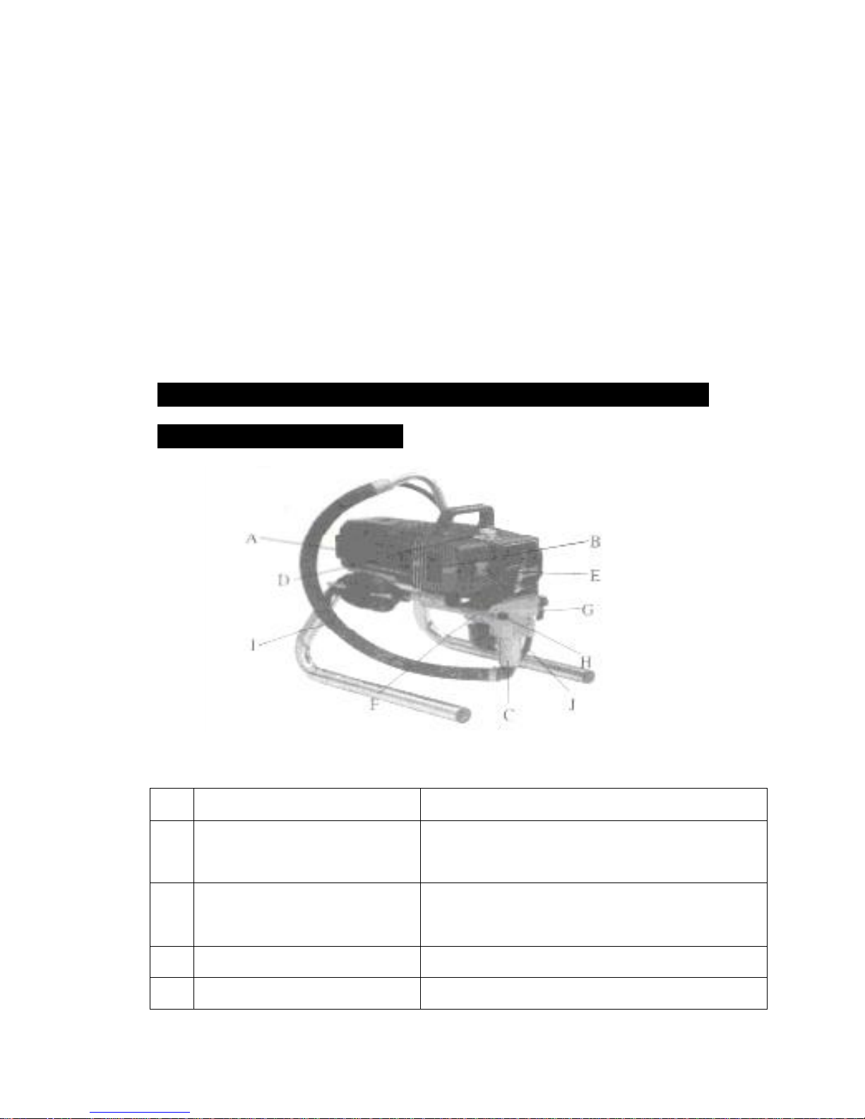
2.Name of equipment Components and features
introduction
A
Motor DC motor ,220V,50HZ,single-phase
B ICS intelligent Pressure controller. Pressure sensors and equipment have suggested that
the status of the equipment fuction
Suction Components
C
Use Within the upper and lower Components for the
two valve coating will be added after the supercharger
and exhaust
D Pressure adjustment Knob /Button Control the coating Pressure export
E On/off switch Control an equipment operation or stop
6
F Pump filters The percolation gets into the coating in the equipment
G Return Valve return to vertical direction for the state open ,the
horizontal direction for spraying state (close)
H Coating painting outlet Link Coating tube and manometer Position
I Suction tube
J Paint return tube Return to the state paint or solvent outflow from here
Will be from buckets in the paint inhalation equipment
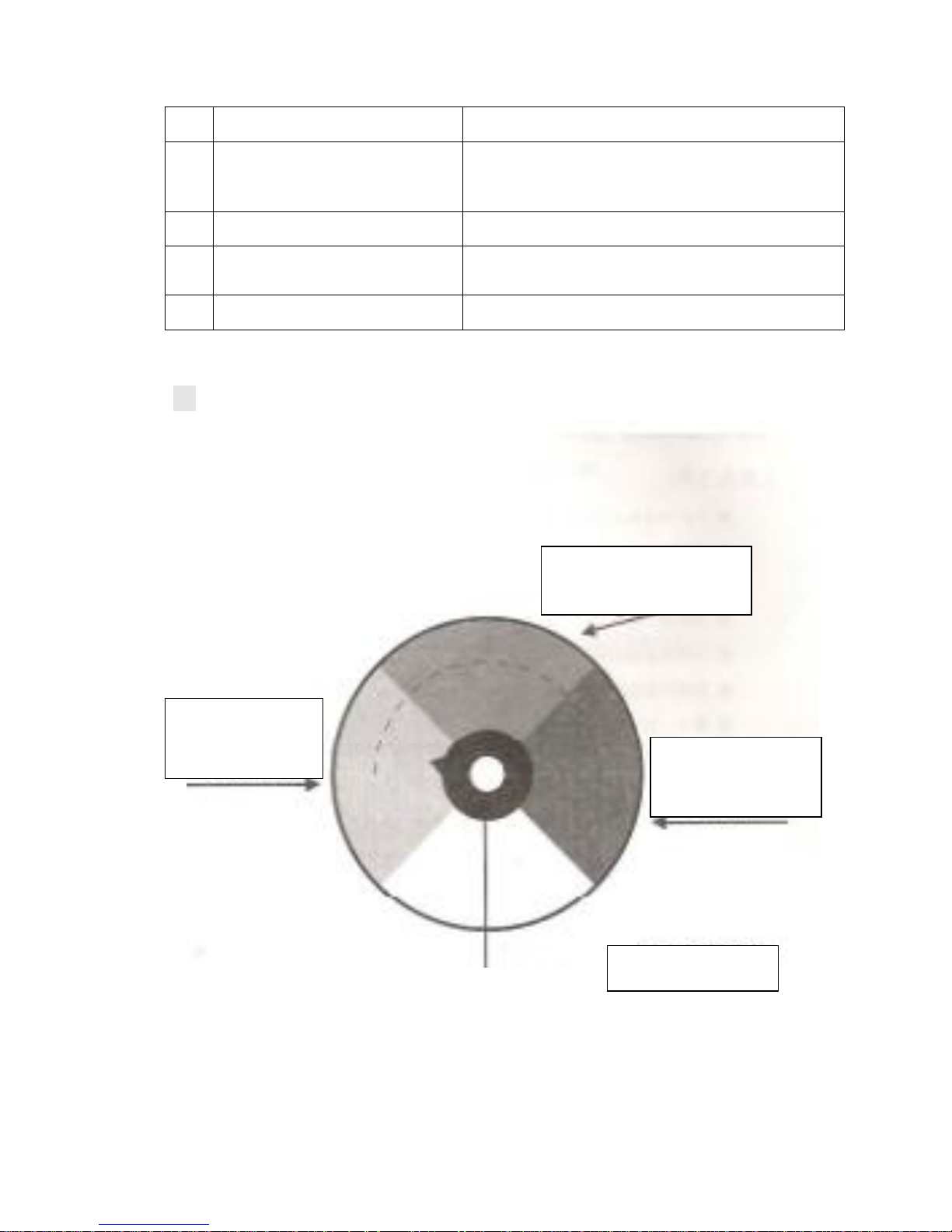
※The pressure control button operating Constructions
Middle pressure area(green)
indicate that middle pressure
Nopressurearea(yello
w) indicate that close
state
High pressure (red)
indicate that high
pressure
pressure control button

7
3. operation
I prepare before switching on.
1. prepare tool:
i. 5-inch,6-inch all within a hexagonal wrench.
ii. Cross screw 4
iii. 14-17、17-19of a double-headed wrench
iv. a blender or a stirring rod
v. antivirus mask and a set of overalls
vi. a brush
vii. some rags
viii. a multimeter
ix. 30-meter,2.5MM² power line extension
x. a power regulator
2. preparetory steps:
⑴assurance suction tube and the reflux tube link the right of position and screwed tightly
⑵firstly contect on the coating manometer exit ,then 15 meter high presure nylon coating
of pressure gauges connected to the export terminal and screwed tightly (pressure gauge
in the first coating to the exit)
⑶havig to use two wrench will be no high-pressure airless spray gun connected to the
head and another screwed tightly .
⑷detemine pressure manometer control buttons set in the display more than 150
locations
(5)multimeter detemined by measureing power supply is 220-250(equipment allowing
fluctutation of voltage )volts of voltage.
(6)equipment will be displayed at the distance of at least 7.5meters in construction place
dry region .

8
3. the initial use of new equipment:
the new equipment of the factory contain a protective effect lubricants,so
the initial use of new equipment need to join the clean water of few soap to
take in to clean ,the flollowing step is cleaning:
⑴add to suction tube containing a little soapy water in the buckets
⑵add to the waste will be returned in the paint barrels\buckets.
(3)return valve will be installed in the vertical direction .
(4)open equipment power switch..
(5)let soapy water to peration equipment in the equipment within the circle ,until the
outflow of clean water from the return tube .
II preparetive before spraying:
before spraying ,they must first determine spray paint has been good
and have been initially harmonic filtering ,otherwise undesirable coating
equipment will in creas wear and reduce the life span of equipment .in
addition ,each time before spraying ,the paint must be used by delicated
diluent (such as spraying latex paint water can be used )to allow equipment
to cycle again and again spraying ,the following is operation steps:
⑴add suction tube will be fitted with special diluent or clean in the bucket.
⑵add to the waste will be returned in paint bucket.
⑶Pressure control buttons will be set in the middle (yellow areas) but the bottom
of the location of equipment functioning.
⑷return valve will be installed in the vertical direction.
⑸Power equipment opened.
⑹equipment to operation 15 to 30 seconds until the clean diluent from the outflow
of return
⑺shut the powers switch.
⑻set the reflux valve to the position of level.
⑼turn on the power switch
 Loading...