

Dinolift Dino 95T Operating Instructions Manual
DINO 95
T
OPERATING INSTRUCTIONS
®
Raikkolantie 145
FI-32210 LOIMAA
T. +358 2 762 5900
F. +358 2 762 7160
dino@dinolift.com
www.dinolift.com
Manufacturer:
Dealer:

DINO 95T
2

DINO 95T
3
ORIGINAL OPERATING INSTRUCTIONS
Valid from serial number 95003

DINO 95T
4
TABLE OF CONTENTS
1 EU DECLARATION OF CONFORMITY ............................................................................6
2 REACH DIAGRAM.................................................................................................................7
3 DIMENSION DRAWING........................................................................................................8
4 TECHNICAL SPECIFICATION............................................................................................9
4.1 EXAMPLE OF THE MACHINE’S NAMEPLATE............................................................................9
4.2 GENERAL DESCRIPTION OF THE MACHINE............................................................................10
4.3 DESCRIPTION OF THE MACHINE’S INTENDED USE.................................................................10
5 GENERAL SAFETY REGULATIONS................................................................................11
5.1 !!
INSTRUCTIONS FOR SAFE OPERATION!..............................................................................13
6 INSPECTIONS........................................................................................................................14
7 WORKSITE INSPECTION...................................................................................................15
8 OPERATION OF SAFETY DEVICES ................................................................................16
9 OPERATING CONTROLS...................................................................................................17
9.1 OPERATING
CONTROLS ON CHASSIS CONTROL PANEL ......................................17
9.2 OPERATING CONTROLS FOR OUTRIGGERS.............................................................18
9.3 OPERATING CONTROLS ON THE PLATFORM ..........................................................19
10 MEASURES TO BE TAKEN IN CASE OF EMERGENCY/AT RISK OF LOSING
THE STABILITY..........................................................................................................................21
11 START-UP ...........................................................................................................................22
11.1 OPERATING THE LIFT FROM THE CHASSIS PANEL.............................................25
11.2 OPERATING
THE LIFT FROM THE PLATFORM PANEL........................................26
12 EMERGENCY DESCENT SYSTEM................................................................................30
13 DRIVING DEVICE (OPTION)..........................................................................................31
14 DRIVING DEVICE (OPTION)..........................................................................................32
15 SPECIAL INSTRUCTIONS FOR WINTER USE...........................................................33
16 MEASURES TO BE TAKEN AT THE END OF THE WORKING DAY....................34
17 PREPARING THE LIFT FOR TRANSPORT.................................................................35
18 INSTRUCTIONS FOR SERVICE AND MAINTENANCE ...........................................37
18.1 GENERAL SERVICE INSTRUCTIONS.......................................................................37
18.2 SERVICE
AND INSPECTION INSTRUCTIONS.........................................................38
18.3 LUBRICATION PLAN ..................................................................................................39
18.4 LONG-TERM
STORAGE..............................................................................................40
18.5 LOAD
HOLDING AND LOAD REGULATION VALVES..........................................41
18.6 WHEEL BRAKES AND BEARINGS............................................................................43

DINO 95T
5
18.7 LEVELLING SYSTEM OF THE PLATFORM .............................................................45
18.8 REGULAR SERVICING................................................................................................46
19 INSPECTION INSTRUCTIONS.......................................................................................52
19.1 FIRST INSPECTION......................................................................................................52
19.1.1 SAMPLE OF INSPECTION PROTOCOL FOR THE ACCESS PLATFORM...53
19.2 DAILY INSPECTION (START-UP INSPECTION) .....................................................55
19.3 MONTHLY INSPECTION (MAINTENANCE INSPECTION)....................................56
19.4 ANNUAL INSPECTION (REGULAR INSPECTION) .................................................57
19.5 EXTRAORDINARY INSPECTION..............................................................................60
19.6 TEST LOADING INSTRUCTIONS FOR REGULAR INSPECTION..........................61
20 FAULT FINDING ...............................................................................................................62
21 GENERAL INFORMATION OF HYDRAULICS ..........................................................68
22 ELECTRIC COMPONENTS.............................................................................................70
22.1 CHASSIS CONTROL CENTRE (LCB), RELAYS........................................................70
22.2 CHASSIS CONTROL CENTRE (LCB), SWITCHES...................................................70
22.3 CHASSIS CONTROL CENTRE (LCB), OTHER ITEMS.............................................71
22.4 PLATFORM CONTROL CENTRE (UCB), SWITCHES..............................................71
22.5 PLATFORM CONTROL CENTRE (UCB), OTHER ITEMS........................................72
22.6 LIMIT SWITCHES.........................................................................................................72
22.7 OTHER MARKINGS.....................................................................................................72
23 ELECTRIC COMPONENTS 95T 95001 -> .....................................................................73
24 ELECTRIC DIAGRAM 95T 95001 ->..............................................................................75
25 HYDRAULIC COMPONENTS 95001 -> .........................................................................86
26 HYDRAULIC DIAGRAM 95001->...................................................................................87

DINO 95T
6
1 EU Declaration of Conformity
EU Declaration of Conformity
Dinolift Oy
Raikkolantie 145
FI-32210 Loimaa,
which has authorised the Chief Engineer Mr. Seppo Kopu to draw up the Technical
Construction File
declares that
DINO 95T Access Platform no YGC 0D95T X X XXXXXX
complies with the provisions of the Machine Directive 2006/42/EC and its
amendments as well as the national decree, through which they have been
brought into effect as well as the regulations of the Low Voltage Directive
2000/14/EC and the EMC Directive 2004/108/EC.
Notified body nr. 0044,
TÜV NORD CERT GmbH
Langemarckstrasse 20
DE-45141 ESSEN,
has granted the certificate No. 44 205 378348
In designing the machine, the following harmonized standards have been
applied:
EN 280/A1+A2; DIN EN 60204-1/A1
Loimaa
12.04.2010
(place) (date)
-----------------------------------------
(signature)
Seppo Kopu
Chief Engineer
(name in block letters, position)
DINO 95T
7
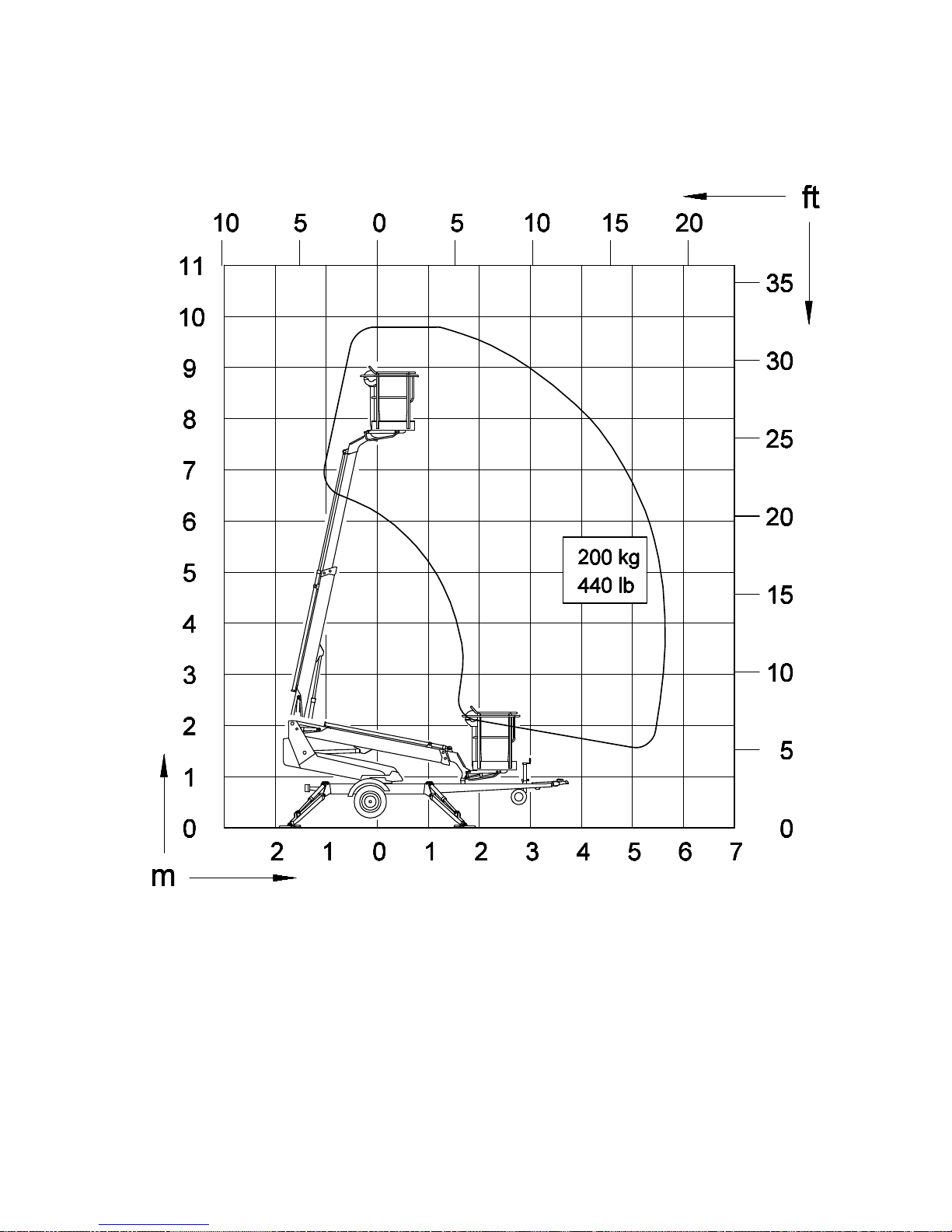
2 REACH DIAGRAM

DINO 95T
8
3 DIMENSION DRAWING

DINO 95T
9
4 TECHNICAL SPECIFICATION
Max. working height 9.7 m
Max. platform height 7.7 m
Max. outreach 5.6 m
Boom rotation continuous
Turn area refer to reach diagram
Support width 3,60 m / 3,90 m
Transport width 1.72 m
Transport length 5.52 m
Transport height 1.96 m
Weight 1,160 kg
Max. allowed load on platform 200 kg
Max. number of persons + additional load 1 person + 120 kg
Max. allowed sideways load (caused by persons) 200 N
Max. lateral inclination (chassis) ±0,3°
Max. wind speed during operation 12,5 m/s
Min. ambient temperature when working -20 °C
Max. support force on the outriggers 9,500 N
Platform size Ø 0,85 m
Gradeability using the driving device (optional) 25%
Power supply:
- mains current: 230V / 50Hz / 10A
- Sound pressure level Under 70 dB
- internal combustion engine (optional) 4.8 kW (6.5 hp)/ 3600 r/min
- Sound pressure level 92 dB
Socket outlets on the platform 230V / 50Hz / 10A
4.1 Example of the machine’s nameplate

DINO 95T
10
4.2 General description of the machine
The denominations of the machine’s essential parts and concepts, which are used later in these
instructions, are described on this page.
4.3 Description of the machine’s intended use
The Access Platform is exclusively intended for transferring people and tools and acting as a
work platform to the limit of its load-bearing capacity and reach (refer to the table of
Technical Specifications and Reach Diagram).
The intended use also covers:
- Following all the instructions in the Operating Instructions
- Performance of the inspections and maintenance operations
DINO 95T
11
5 GENERAL SAFETY REGULATIONS
Make yourself familiar with these operation instructions before using the lift!
- Keep these operating instructions in the place reserved for them.
- Make sure that all users of the lift are familiar with these instructions.
- Advice the new users and strictly follow all instructions given by the manufacturer.
- Make sure you clearly understand all instructions relating to the operational safety of the lift.
Always use chocks under the wheels when disconnecting the lift from the car.
Only specially trained personnel with authorisation in writing from the employer who are
well familiarised with the device and at least 18-years old are allowed to operate the lift
- The max. allowed load on the platform is one (1) person and at maximum hudred twenty (120)
kg of additional load, however, the total load must not exceed one two hundred (200) kg.
- The platform may only be operated when the chassis is well supported and the wheels are off
the ground.
- The load-bearing capacity and the gradient of the base must be taken into account when
supporting the chassis.
- Additional support plates of adequate size must be used under the outriggers when working on
soft ground. Only use such additional support plates on which the metallic outriggers will not
slide.
The lift may only be moved in the transport position. No persons or load are allowed on the
platform during the transportation.
The weather conditions, such as wind, visibility and rain, must always be taken into account so
that these factors will not adversely affect the safe performance of the lifting operations.
The use of the lift is prohibited if
- the temperature drops under - 20 °C or
- the wind speed exceeds 12.5 m/s
PROTECT YOUR HEARING WHILE USING THE POWER UNIT (OPTIONAL) 92 dB
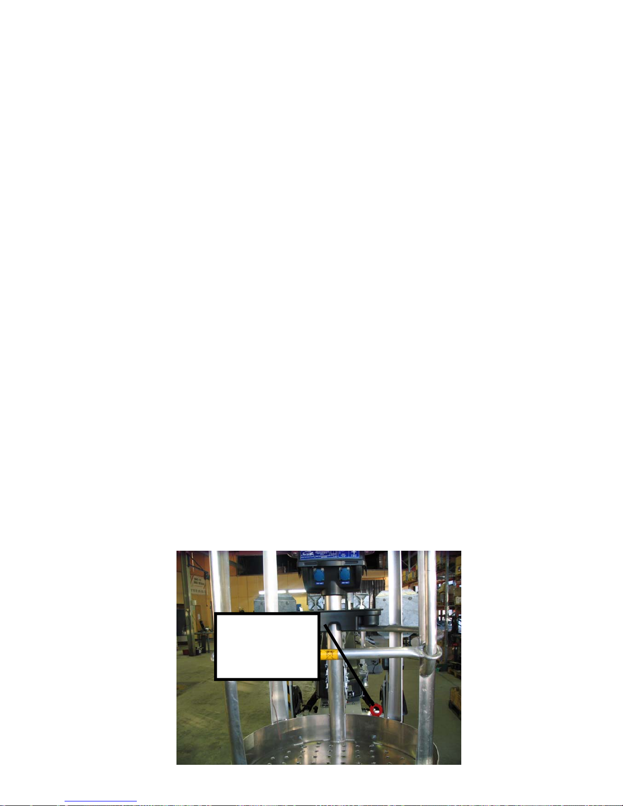
USE THE SAFETY HARNESS
Connecting points
for the safety
harness.
1 person/lug

DINO 95T
12
Do not use ladders, steps or other similar equipment on the platform.
Never throw any objects from the platform.
The lift must not be used for transferring goods or persons between different floors or working
levels.
Always make sure before lowering the platform that the area on the underside is clear of any
obstructions.
Avoid damaging the platform by lowering it on the ground or bringing it in contact with any
structures.
When working in busy areas the operating range of the lift must be clearly marked either by using
warning lights or fencing.
Also observe the regulations of the Road Traffic Act.
Beware of the live aerial power lines in the area - observe the minimum safety distances:
Keep the lift clean of any dirt which may impair the safe operation and impede the inspection of
the structures
The device must be serviced and inspected regularly.
Only skilled persons who are familiar with the service and reparation instructions are allowed to
carry out the service and reparation work.
It is strictly prohibited to use a lift which is out of order.
The operator must be given instructions and consent from the manufacturer
for all such specific work methods or conditions, which the manufacturer has
not explicitly defined
The device must neither be altered without the manufacturer’s consent nor be used under
conditions which do not meet the requirements set by the manufacturer.
Voltage Min. distance below
(m)
Min. distance at the
side (m)
100 – 400 V hanging spiral
cable
0,5 0,5
100 – 400 V open-wire cable 2 2
6 – 45 kV 2 3
110 kV 3 5
220 kV 4 5
400 kV 5 5

DINO 95T
13
5.1 !! Instructions for safe operation!
- Use a safety harness while on the platform.
- Use hearing protectors when operating the power unit (optional) from the chassis panel.
Sound pressure level 92 dB.
- Never load the platform while in the upper position.
- The lift must not be used when the temperature is below -20°C and the wind speed
exceeds 12.5 m/s.
- Beware of live power lines within the work area.
- The lift MUST NOT be used as a crane.
- Always ensure the load-bearing capacity of the standing surface.
- Ensure the unobstructed range of movement before operating the outriggers.
- While in the support position, ensure that the wheels are off the ground.
- Always verify the horizontal position of the machine.
- Ensure that the outriggers cannot slide while on a gradient.
- Always ensure that the work area is clear of outsiders. Danger of getting squeezed
between rotating and fixed structures.
- Stepping on or off the platform in motion is prohibited.
- The maximum-allowed gradient during transfers is 5°. During transfer in rough terrain,
try to stay above the machine.
- While operating the boom from the control panel on the turning device, beware of
getting pressed against the outriggers or other structures that do not turn with the boom.
- When the boom is in its lowest positions, make sure it cannot clash during rotation with
structures that do not turn with the boom.
- Before operating, always ensure that the safety devices and the emergency descent
system are in working order.
- Do not take tools/material of large surface area onto the platform. The increase in wind
load may jeopardize the stability of the device.
- Always keep the lift free from dirt, snow and ice.
- Ensure that the lift is inspected and serviced, before use.
- Never use a defective lift.

DINO 95T
14
- Never use a lift alone. Make sure, there is always someone on the ground, who can call
for help in case of an emergency.
6 INSPECTIONS
A thorough inspection of the lift must be carried out at least once every twelve (12) months.
The inspection shall be carried out by a technically trained person who is familiar with the
operation and structure of the lift.
Draw up a protocol of the inspections and keep it always with the unit stored in the space reserved
for it.
Carry out the inspections on regular basis throughout the service life of the lift.
The inspection must be carried out within twelve (12) months from the first or the previous
inspection.
If the lift is used under extreme conditions, intervals between the inspections shall be reduced.
The overall operating condition of the lift as well as the condition of the safety-related control
devices shall be established in the regular inspections. Particular attention shall be paid to changes
which affect the operational safety.
In connection with the regular inspection, it shall be established to what extent the lessons and
practical experience gained from the previous inspection can be implemented for even better
safety.
NOTE! Primarily the national legislation must be followed!
Regular inspections and service measures are described more thoroughly in the chapter "Serviceand maintenance".

DINO 95T
15
7 WORKSITE INSPECTION
1. General information
- Is the lift suited for the intended job?
- Is the performance of the lift sufficient for the job? (reach, loadability etc.)
- Is the position of the lift safe?
- Is the lighting on the worksite sufficient?
2. Documents
- Are the Operation and Service Instructions for this lift present? (Manufacturer´s
instructions)
- Are inspections and servicing carried out in accordance with the instructions and have the
defects affecting the safety been checked as repaired?
(Inspection protocols)
3. Structure (Visual inspection and operational test)
- General condition of the lift
- Operation and protection of the controls
- Emergency stop, signal horn and limit switches
- Electrical appliances and wiring
- Oil leaks
- Load markings and signs
4. Operator
- Is the operator old enough?
- Has the operator received the required training?
5. Special issues on the work site
- Are there any additional regulations relevant to the worksite or the work?
DINO 95T
16
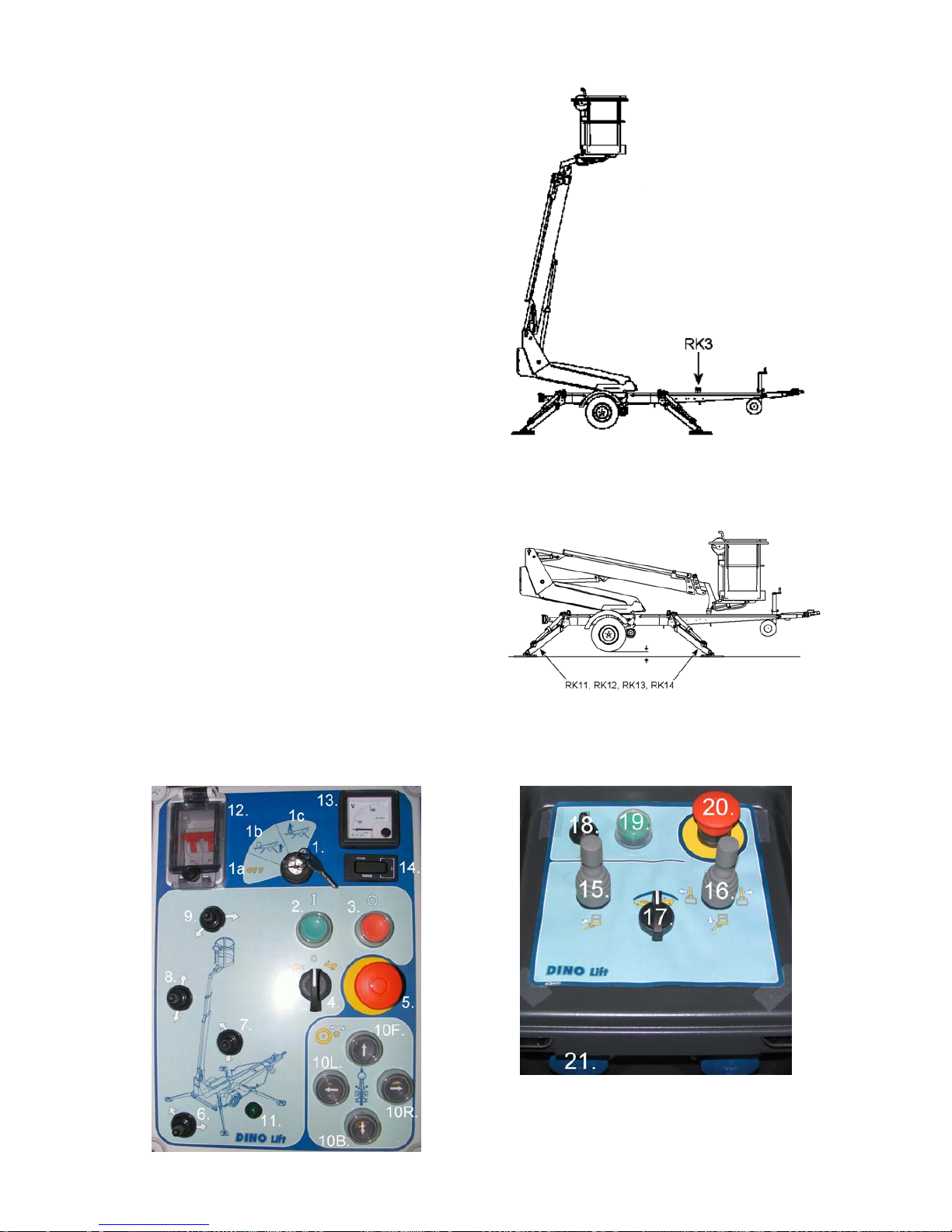
8 OPERATION OF SAFETY
DEVICES
1. Support outriggers
The safety limit switch RK3 prevents the
operation of the outriggers and the driving device
when the boom does not rest on the transport
support. The switch is located on the tow-bar at
the transport support.
2. Lifting of the boom
All the lift’s support outriggers must be in the
support position before the boom is lifted. Make
sure that the wheels are off the ground. The safety
limit switches RK11, RK12, RK13 ja RK14 are
located on the support outriggers.
3. As the emergency stop button is depressed all movements stop and the power unit is
turned off. The emergency stop pushbutton must be pulled up before the power unit can be

DINO 95T
17
restarted (buttons 5 and 20)
Check operation of the safety devices.
9 OPERATING CONTROLS
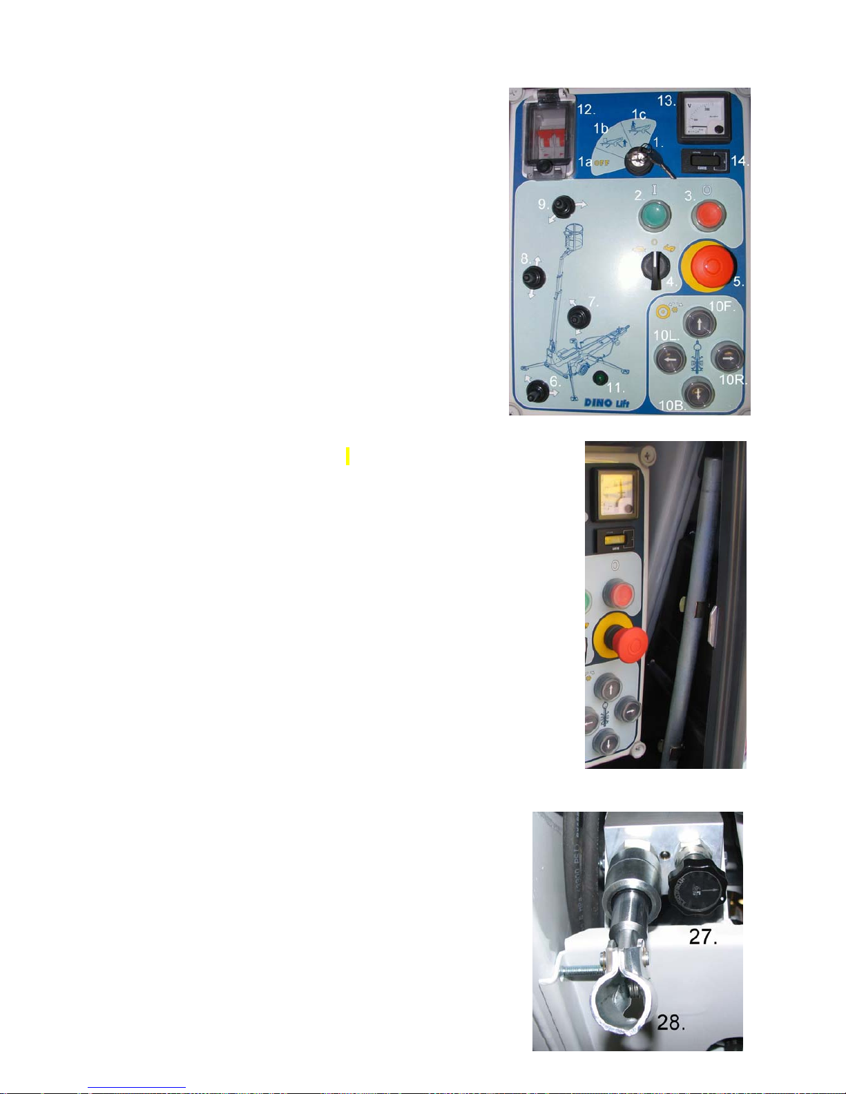
9.1 OPERATING CONTROLS ON CHASSIS CONTROL PANEL
1. Selector switch
1a - ignition off
1b -outriggers, hydraulic drive and operating the boom from the
chassis panel
1c -controlling the boom from the platform panel
2. Start button
3. Stop button
4. I/ II - speed (is used simultaneously with the control levers for the boom and the
driving device)
5. Emergency stop button
6. Lever for turning
7. Lever for boom system
8. Lever for telescope movement
9. Lever for platform inclination
10F. Drive to the front
10B. Drive to the rear
10F. Drive to the right (forward)
10F. Drive to the left (forward)
10B 44Ah Drive to the right (backward)
10B+10L Drive to the left (backward)
11. Signal light for the outrigger
limit switches
12. Automatic fuse for socket
outlets
13. Voltage meter
14. Hour meter
DINO 95T
18
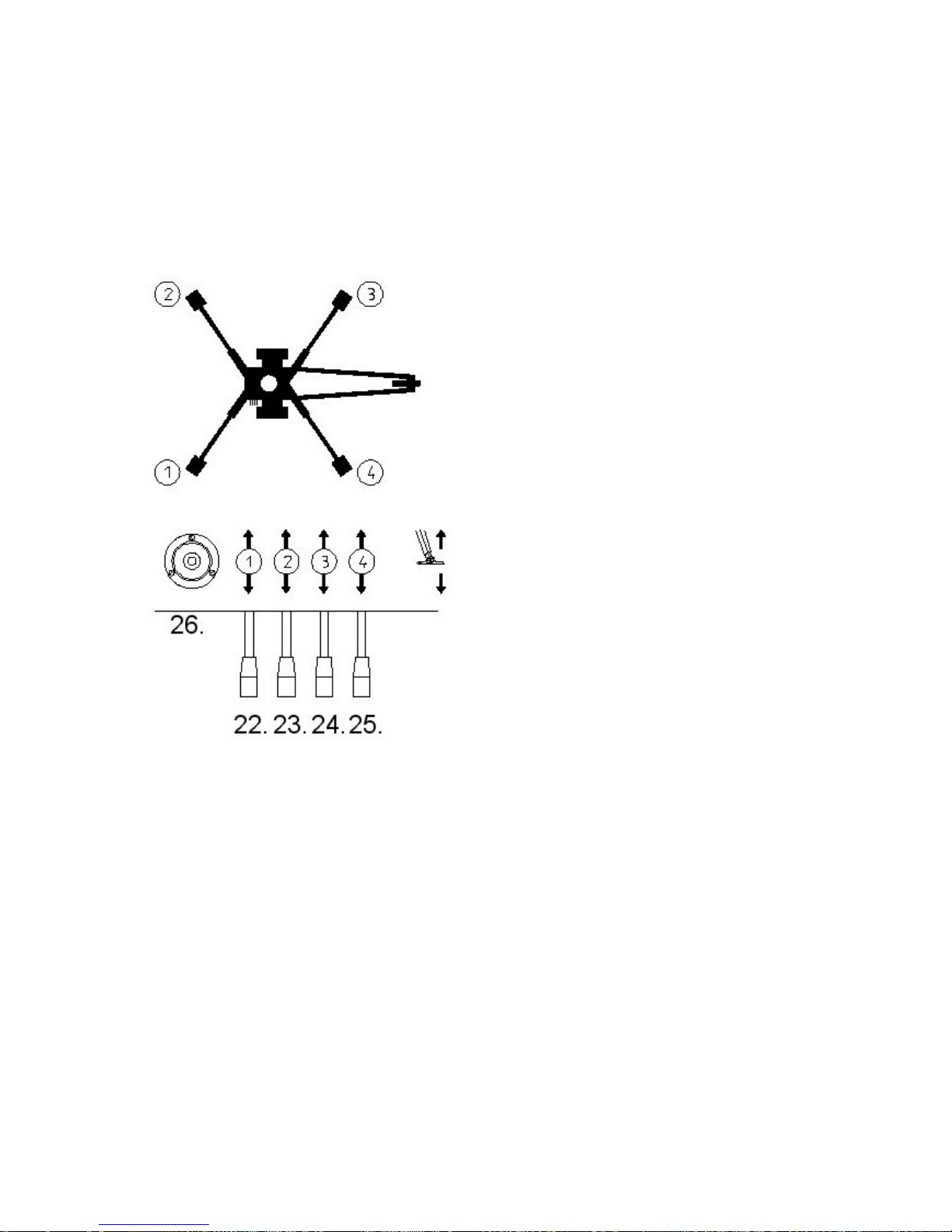
9.2 OPERATING CONTROLS FOR OUTRIGGERS
22. Rear outrigger, right
23. Rear outrigger, left
24. Front outrigger, left
25. Front outrigger, right
26. Position indicator of chassis
DINO 95T
19
9.3 OPERATING CONTROLS ON THE PLATFORM
Close the cover of the chassis control panel before operating the platform controls.
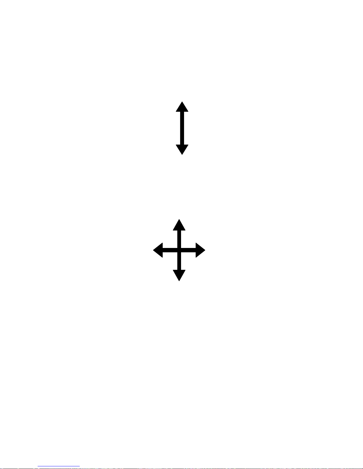
15. Control lever
TELESCOPE IN
TELESCOPE OUT
16. Control lever
BOOM UP
BOOM TO THE LEFT
BOOM TO THE RIGHT
BOOM DOWN

DINO 95T
20
17. I/ II - speed (is used simultaneously with the control levers for the boom and the levelling of
the platform)
18. Control lever for levelling of the platform
19. Sound signal
20. Emergency stop button
21. Socket outlet 230VAC/ (2 pcs.)

DINO 95T
21
10 MEASURES TO BE TAKEN IN CASE OF EMERGENCY/AT RISK OF
LOSING THE STABILITY
Reduced stability can be caused by a fault in the lift, the wind or other lateral force, collapse of the
standing base or negligence in providing sufficient support. In most cases one sign of reduced
stability is the inclination of the lift.
WHEN AT RISK OF LOSING THE STABILITY
1. If there is time, try to find out the reason for the reduced stability and the direction of its
effect. Warn other people on the work site using the alarm signal.
2. If possible, reduce the load from the platform in a safe manner.
3. Reduce the outreach to the side by retracting the telescope. Avoid abrupt movements.
4. Turn the boom away from the danger zone, i.e. to a position where the stability of the lift is
normal.
5. Lower the boom.
If the stability has been lost as a result of a fault in the lift, repair such a fault immediately.
Do not use the lift until the fault has been repaired and the condition of the lift has been
verified.
IN CASE OF OVERLOADING
1. If there is time, try to find out the reason for the reduced stability and the direction of its
effect. Warn other people on the work site using the alarm signal.
2. If possible, reduce the load from the platform in a safe manner.
3. Reduce the outreach to the side by retracting the telescope.
IN CASE THE POWER SUPPLY IS INTERRUPTED (power unit/combustion engine)
1. Lower the boom using the emergency descent system (see point “Emergency descent system”)
2. Establish the reason why the energy supply was interrupted.
IN CASE OF MALFUNCTION, WHEN EVEN THE EMERGENCY DESCENT SYSTEM IS
NOT OPERATIONAL
1. If the emergency descent system does not operate, try to warn other personnel present on the
site or call for help so that the power supply required for normal operation can be resumed or the
lift can be made operational by some other means so that the person on the platform can be
lowered safely down.
DINO 95T
22
11 START-UP
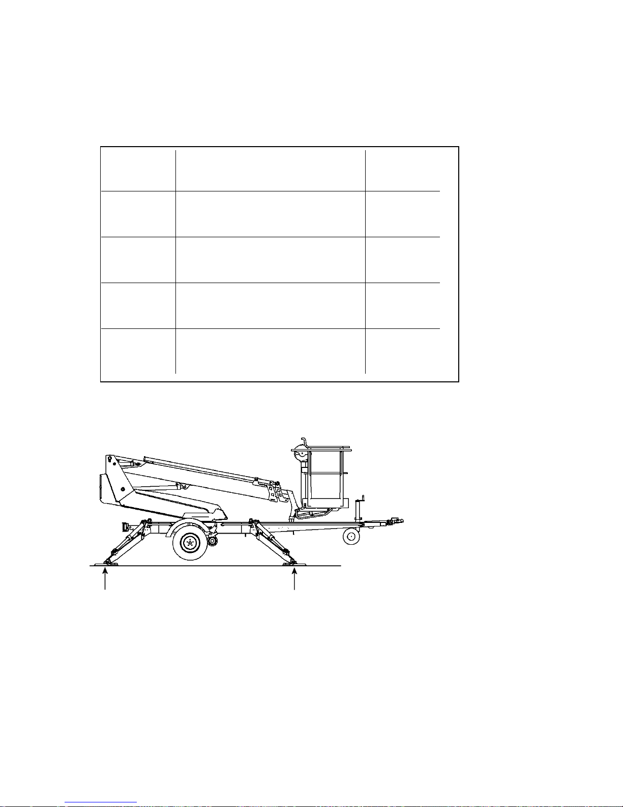
1. Ground stability
- make sure that the ground is even and hard enough to support the lift in a steady level position
- if the ground is soft, use sufficiently large and sturdy additional plates under the support
outriggers
- observe the effect of ice, possible rain and inclination of the surface on the support (the
support outriggers must not slip on the surface)
- the operation is prohibited if the lift is not properly supported and in a level position
2. Drive or push the lift to the inspected lifting site
- apply the parking brake
- disconnect the lift from the towing vehicle
Soil material Density Max. ground
pressure
P kg/cm²
Gravel High density 6
Medium density 4
Loose 2
Sand High density 5
Medium density 3
Loose 1,5
Fine sand High density 4
Medium density 2
Loose 1
Sand/ mud High density (very hard to work) 1,00
Medium density (hard to work) 0,50
Loose (easily worked) 0,25

DINO 95T
23
3. Connection of power supply to the lift
A. Powered by ac-supply. While the mains voltage is plugged in, the12VDC supplied by a
separate unit.
- connect the mains cable to the power supply
- for maximum out of the electric motor the voltage must 230 VAC (-10 % +6 %), the frequency
must be 50 Hz and rating of the fuse 10A (the length of the connecting cable has some effect)
4. To access the operating controls, open the cover at the rear of the turning device
5. Turn the selector switch (1) to position 1b
6. Start the engine with button 2 (green)

DINO 95T
24
7. Lower the front support outriggers (on the tow-bar side)
8. Lower the rear support outriggers (do not
damage the tow-bar jockey wheel)
9. Level the chassis with the outriggers with the
help of the level gauge (26).
MAKE SURE THAT THE WHEELS ARE CLEARLY OFF THE GROUND
- the (green) signal light 11 on the chassis control panel comes on when all outriggers are in the
lower position and the outrigger limit switch circuit is connected
- make sure all outriggers are firmly supported on the ground
DINO 95T
25
11.1 OPERATING THE LIFT FROM THE CHASSIS
PANEL
10. Turn the selector switch (1) to position 1b
- nyt voit ajaa puomistoa alahallintavivuista 6, 7, 8 ja
työkoria vivusta 9. Puomiston liikkeitä ajettaessa tulee
samalla kääntää vivusta 4 (I/ II – nopeus)
- test the operation of the emergency descent system as
follows:
1. Start by lifting the boom about 1 – 2 metres (with lever
7) and continue by extending the telescope 1 – 2 metres
(with lever 8) keeping the emergency stop button
depressed. The movement should now stop.
2. Open the emergency descent valve for the telescope by
turning the lever 27 clockwise and retract the telescope completely
by pumping with hand pump 28. The crank for the hand pump is
located at the side of the chassis control panel (see adjacent picture).
3. Open the emergency descent valve for the boom by turning the lever
27 counter-clockwise and lower the boom by pumping with hand
pump 28.
4. Close the emergency descent valve by turning the lever 27 to its
centre position
5. Pull up the emergency stop button.
DO NOT DAMAGE THE TOW-BAR JOCKEY WHEEL!
Lock the selector switch (1) in position 1a before working
under the boom.
Make sure that neither people nor load are on the platform.

DINO 95T
26
11.2 OPERATING THE LIFT FROM THE PLATFORM PANEL
11. Turn the selector switch (1) to position 1c (operating from the platform) and take away
the key (see point "Operating controls on the chassis control panel")
- Now you can operate the boom using levers 15 and 16 on the platform control panel.
Simultaneously, turn the switch 17 (I/ II - speed).
Only use the II-speed with short boom and low platform height.
Whenever possible, keep the boom short while lifting and lowering the platform.
DO NOT DAMAGE THE TOW-BAR JOCKEY WHEEL!

DINO 95T
27
IF THE SAFETY DEVICES OR THE EMERGENCY DESCENT SYSTEM ARE NOT
WORKING, HAVE THEM REPAIRED BEFORE OPERATING THE LIFT!
12. Refer to the item "Daily inspections" in the task list for servicing.
13. With the boom slightly lifted and the telescope extended, make sure that the platform
does not lower of itself while the operating controls are not being used.
14. When working under cold weather conditions, let the engine run for a while without load
to increase the hydraulic oil temperature. Start the operations by driving the movements
carefully without load back and forth from the chassis control panel.
15. Move the platform to the work object
If several control levers are operated simultaneously, only the movement with the least resistance
will operate.
NOTE!
Lowering the platform to transport position: Always retract the telescope completely before
lowering the boom onto the transport support.
DO NOT DAMAGE THE TOW-BAR JOCKEY WHEEL!
DO NOT TAKE ADDITIONAL LOAD IN THE UPPER POSITION!
16. Working a long time in the same position
- There are pushbuttons for both stopping and starting the engine on the chassis control
panel. When the weather is warm and the platform is kept for a longer period in the same
position, it is not necessary to let the engine run continuously.
- when the weather is cold, it is recommended to let the engine run to keep the hydraulic oil
warm
- check the stability and condition of the base regularly during the operation, taking into
account the weather and ground conditions
- The engine is switched off if the key is turned to position 1c and starts automatically when
the speed is selected from the platform control panel using the switch 17 but stops again,
after a delay of 4 seconds, if the switch is not turned.
 Loading...