

Dinolift DINO 260XTD Operating Instructions Manual
DINO ® 260XTD
OPERATING INSTRUCTIONS
®
Raikkolantie 145
FI-32210 LOIMAA
T. +358 2 762 5900
F. +358 2 762 7160
dino@dinolift.com
www.dinolift.com
Manufacturer:
Dealer:

DINO 260XTD
2

DINO 260XTD
3
ORIGINAL OPERATING INSTRUCTIONS
Valid from serial number 26323

DINO 260XTD
4
TABLE OF CONTENTS
1 EU DECLARATION OF CONFORMITY......................................................................................6
2 REACH DIAGRAM...........................................................................................................................7
3 DIMENSION DRAWING..................................................................................................................8
4 TECHNICAL SPECIFICATION .....................................................................................................9
4.1 EXAMPLE OF THE MACHINE’S NAMEPLATE......................................................................................9
4.2 GENERAL DESCRIPTION OF THE MACHINE......................................................................................10
4.3 DESCRIPTION OF THE MACHINE’S INTENDED USE ..........................................................................10
5 GENERAL SAFETY REGULATIONS .........................................................................................11
5.1 !! INSTRUCTIONS FOR SAFE OPERATION! .......................................................................................13
6 INSPECTIONS.................................................................................................................................14
7 WORKSITE INSPECTION............................................................................................................15
8 OPERATION OF SAFETY DEVICES..........................................................................................16
9 OPERATING CONTROLS.............................................................................................................18
9.1 OPERATING CONTROLS ON THE CHASSIS CONTROL PANEL .......................................18
9.2 OPERATING CONTROLS ON THE PLATFORM....................................................................19
10 MEASURES TO BE TAKEN IN CASE OF EMERGENCY/AT RISK OF LOSING THE
STABILITY.............................................................................................................................................22
11 START-UP.....................................................................................................................................23
11.1 GROUND STABILITY...................................................................................................................23
11.2 STARTING THE ENGINE...............................................................................................................25
11.3 O
PERATING THE SUPPORT OUTRIGGERS FROM THE CHASSIS PANEL............................................26
11.4 OPERATING THE SUPPORT OUTRIGGERS FROM THE PLATFORM PANEL........................................27
11.5 U
SING THE CHASSIS CONTROL PANEL.........................................................................................28
11.6 U
SING THE CONTROL PANEL ON THE PLATFORM ........................................................................29
11.7 D
RIVING DEVICE........................................................................................................................29
11.8 BOOM MOVEMENTS FROM THE PLATFORM PANEL......................................................................31
11.9 B
OOM MOVEMENTS FROM THE CHASSIS CONTROL PANEL ..........................................................31
11.10 T
EST THE OPERATION OF THE OUTREACH LIMIT SWITCH RK4....................................................32
11.11 DRIVING INSTRUCTIONS.............................................................................................................33
12 EMERGENCY DESCENT SYSTEM .........................................................................................35
13 SPECIAL INSTRUCTIONS FOR WINTER USE ....................................................................37
14 MEASURES TO BE TAKEN AT THE END OF THE WORKING DAY..............................37
15 PREPARING THE LIFT FOR TRANSPORT ..........................................................................38
16 CONNECTION TO THE TOWING VEHICLE .......................................................................39
17 INSTRUCTIONS FOR SERVICE AND MAINTENANCE.....................................................40
17.1 GENERAL SERVICE INSTRUCTIONS.................................................................................40
17.2 SERVICE AND INSPECTION INSTRUCTIONS ..................................................................41

DINO 260XTD
5
17.3 WHEEL BRAKES AND BEARINGS......................................................................................42
17.4 LUBRICATION
PLAN............................................................................................................45
17.5 LONG-TERM
STORAGE........................................................................................................46
17.6 LOAD HOLDING AND LOAD REGULATION VALVES....................................................47
17.7 LEVELLING SYSTEM OF THE PLATFORM.......................................................................49
17.8 REGULAR SERVICING .........................................................................................................50
17.8.1 TESTING THE OUTREACH LIMIT SWITCH...................................................................55
17.8.2 SETTING OF THE OUTREACH LIMIT SWITCH AND THE OVERLOAD LIMIT
SWITCH 57
18 INSPECTION INSTRUCTIONS.................................................................................................61
18.1 FIRST INSPECTION ...............................................................................................................61
18.2 SAMPLE
OF INSPECTION PROTOCOL FOR THE ACCESS PLATFORM........................62
18.3 DAILY
INSPECTION (START-UP INSPECTION)...............................................................64
18.4 MONTHLY INSPECTION (MAINTENANCE INSPECTION) .............................................65
18.5 ANNUAL INSPECTION (REGULAR INSPECTION)...........................................................66
18.6 EXTRAORDINARY INSPECTION........................................................................................69
18.7 TEST LOADING INSTRUCTIONS FOR REGULAR INSPECTION....................................70
19 FAULT FINDING.........................................................................................................................71
20 OPERATION OF ELECTRIC COMPONENTS.......................................................................77
20.1 MAIN CENTRE (PK), RELAYS .............................................................................................77
20.2 MAIN CENTRE (LCB), SWITCHES ...............................................................................................78
20.3 MAIN CENTRE (LCB), OTHER ITEMS ..........................................................................................79
20.4 CONTROL CENTRE (UCB), RELAYS............................................................................................80
20.5 CONTROL CENTRE (UCB), SWITCHES ........................................................................................80
20.6 CONTROL CENTRE (UCB), OTHER ITEMS ...................................................................................81
20.7 CONTROL CENTRE ON CHASSIS (CCB), SWITCHES (EMERGENCY DESCENT OPERATIONS)...........81
20.8 CONTROL CENTRE ON CHASSIS (CCB), OTHER ITEMS ................................................................81
20.9 CHASSIS, OTHER ITEMS ..............................................................................................................82
20.10 LIMIT SWITCHES ........................................................................................................................82
20.11 TURNING DEVICE (RU), OTHER ITEMS........................................................................................83
21 ELECTRIC DIAGRAM 26323 >.................................................................................................84
22 HYDRAULIC COMPONENTS.................................................................................................103
23 HYDRAULIC DIAGRAM .........................................................................................................
104

DINO 260XTD
6
1 EU Declaration of Conformity
EU Declaration of Conformity
Dinolift Oy
Raikkolantie 145
FI-32210 Loimaa,
which has authorised the Chief Engineer Mr. Seppo Kopu to draw up the Technical
Construction File
declares that
DINO 260 XTD Access Platform no YGC D260XT X X XXXXX
complies with the provisions of the Machine Directive 2006/42/EC and its
amendments as well as the national decree, through which they have been brought
into effect as well as the regulations of the Low Voltage Directive 2000/14/EC and
the EMC Directive 2004/108/EC.
Notified body nr. 0537,
VTT
P.O.Box 1300
FI-33101 Tampere
FINLAND
has granted the certificate no. VTT 177 / 524 / 09
In designing the machine, the following harmonized standards have been applied:
EN 280/A1+A2; DIN EN 60204-1/A1
Loimaa 03.02.2012
(place) (date)
-----------------------------------------
(signature)
Seppo Kopu
Chief Engineer
(name in block letters, position)
DINO 260XTD
7
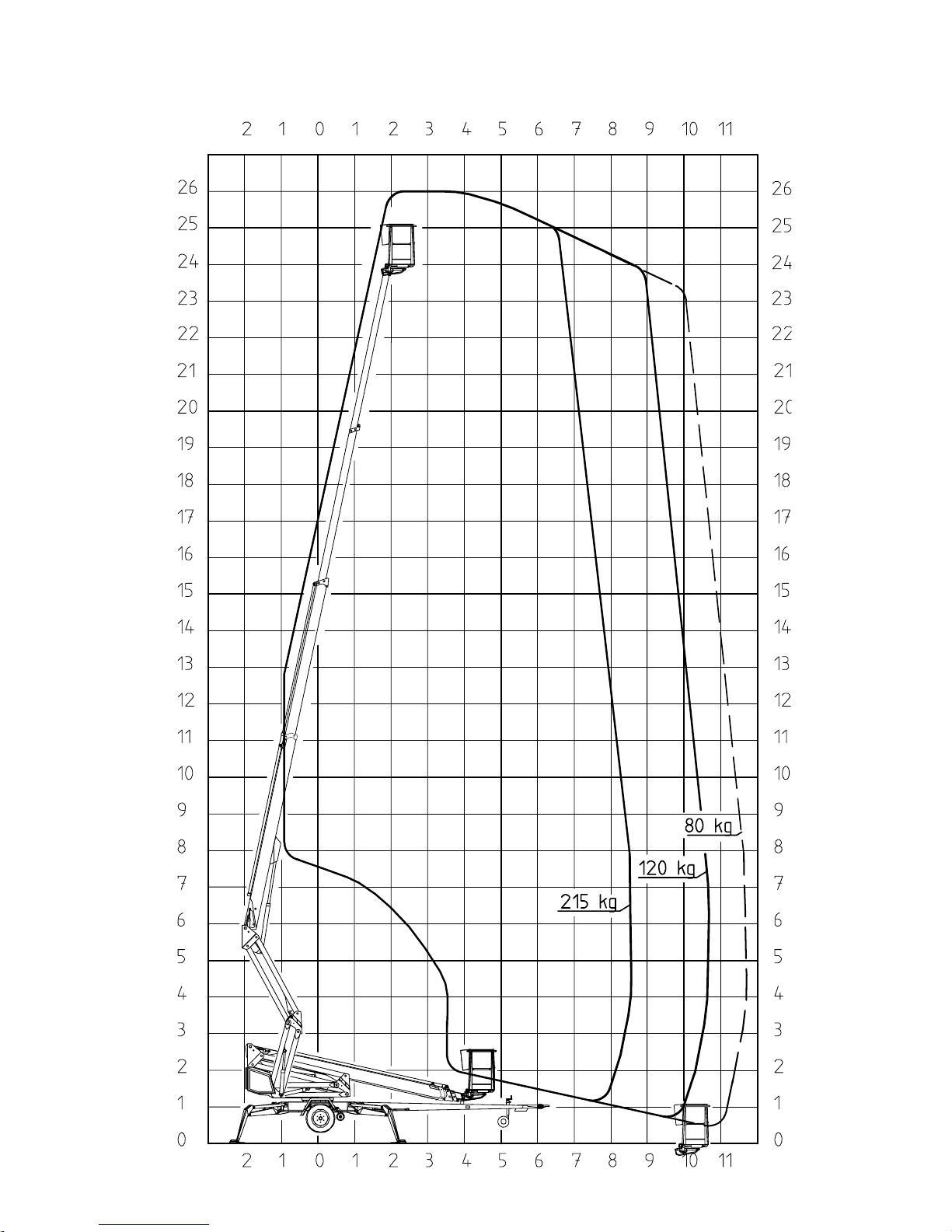
2 REACH DIAGRAM
DINO 260XTD
8
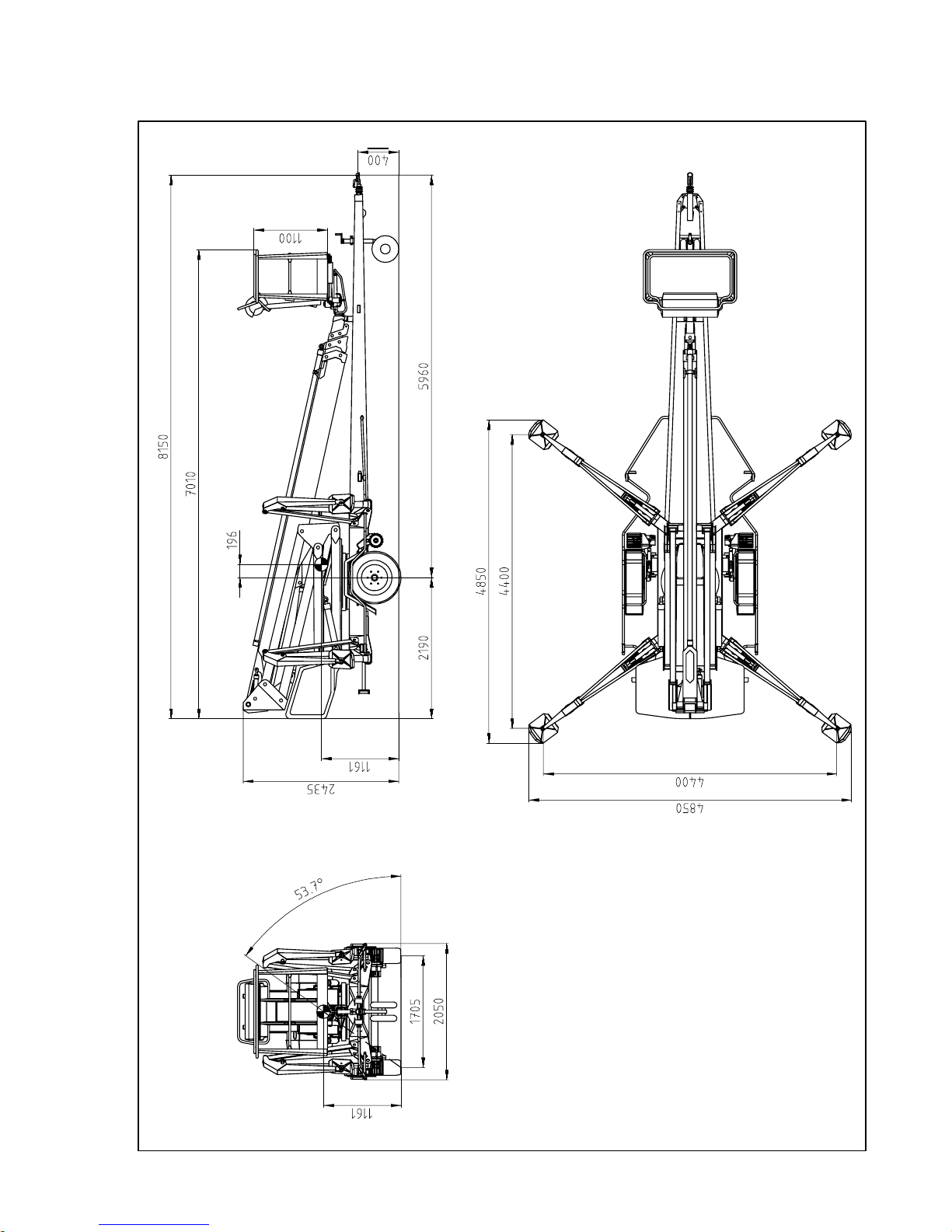
3 DIMENSION DRAWING
DINO 260XTD
9
4 TECHNICAL SPECIFICATION
Max. working height 26.0 m
Max. platform height 24.0 m
Max. outreach 11.7 m
Boom rotation continuous
Platform rotation 90°
Turn area refer to reach diagram
Support width 4.40 m
Transport width 2.05 m
Transport length 8.11 m
Transport height 2.43 m
Weight (without power unit) 3,495 kg
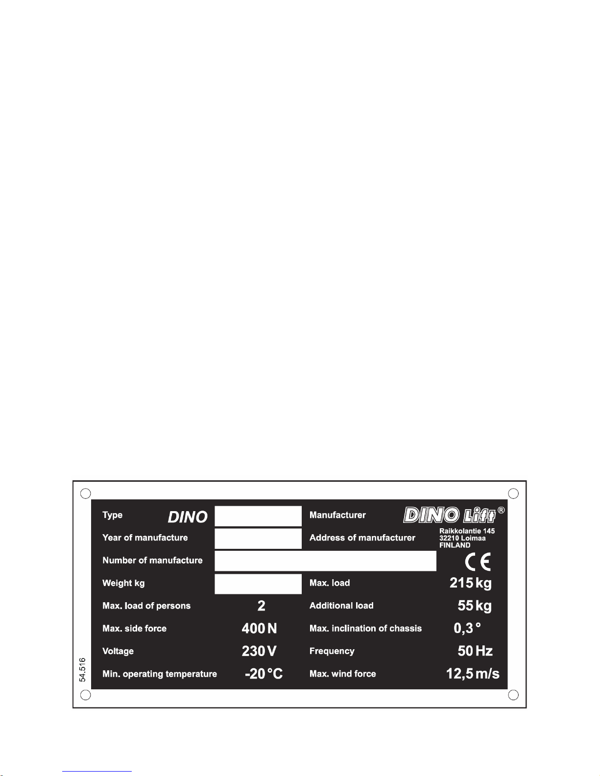
Max. allowed load on platform 215 kg
Max. number of persons + additional load 2 persons + 55 kg
Max. allowed sideways load (caused by persons) 400 N
Max. lateral inclination (chassis) ±0,3°
Max. wind speed during operation 12.5 m/s
Min. ambient temperature when working -20 °C
Max. support force on the outriggers 22,800 N
Työkorin koko 0.7 x 1.3 m
Gradeability 25 %
Power supply:
- mains current: 230V / 50Hz / 16A
- Sound pressure level Under 70 dB
- internal combustion engine 9.6 kW (13 hp)/ 3600 r/min
- Sound pressure level Under 82 dB
Socket outlets on the platform 230V / 50Hz / 10A
4.1 Example of the machine’s nameplate
DINO 260XTD
10
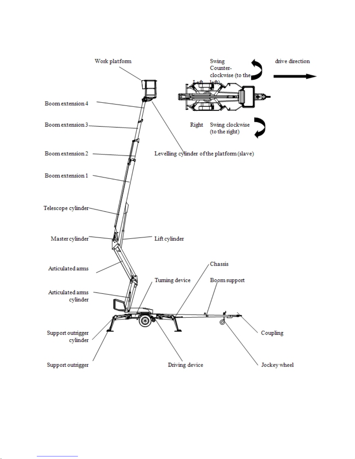
4.2 General description of the machine
The denominations of the machine’s essential parts and concepts, which are used later in these
instructions, are described on this page.
4.3 Description of the machine’s intended use
The Access Platform is exclusively intended for transferring people and tools and acting as a work
platform to the limit of its load-bearing capacity and reach (refer to the table of Technical
Specifications and Reach Diagram).
The intended use also covers:
- Following all the instructions in the Operating Instructions
- Performance of the inspections and maintenance operations
DINO 260XTD
11
5 GENERAL SAFETY REGULATIONS
Make yourself familiar with these operation instructions before using the lift!
Keep these operating instructions in the place reserved for them.
Make sure that all users of the lift are familiar with these instructions.
Advice the new users and strictly follow all instructions given by the manufacturer.
Make sure you clearly understand all instructions relating to the operational safety of the lift.
Always use chocks under the wheels when disconnecting the lift from the car.
Only specially trained personnel with authorisation in writing from the employer who are well
familiarised with the device and at least 18-years old are allowed to operate the lift
- The max. allowed load on the platform is two (2) persons and at maximum fifty five (55) kg of
additional load, however, the total load must not exceed two hundred fifteen (215) kg.
- The platform may only be operated when the chassis is well supported and the wheels are off the
ground.
- The load-bearing capacity and the gradient of the base must be taken into account when
supporting the chassis.
- Additional support plates of adequate size must be used under the outriggers when working on
soft ground. Only use such additional support plates on which the metallic outriggers will not
slide.
- The lift may only be moved in the transport position. No persons or load are allowed on the
platform during the transportation.
- The weather conditions, such as wind, visibility and rain, must always be taken into account so
that these factors will not adversely affect the safe performance of the lifting operations.
The use of the lift is prohibited if
- the temperature drops under - 20 °C or
- the wind speed exceeds 12.5 m/s
PROTECT YOUR HEARING WHILE USING THE POWER UNIT 82 dB
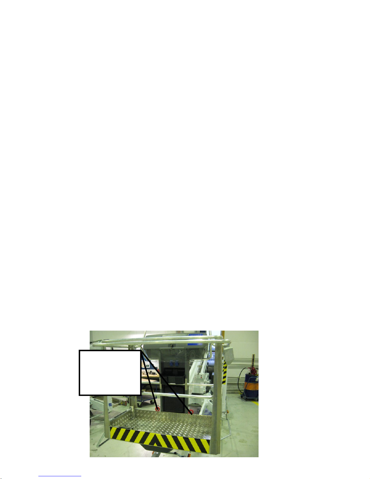
USE THE SAFETY HARNESS!
Connecting points
for the safety
harness.
1 person/lug

DINO 260XTD
12
Do not use ladders, steps or other similar equipment on the platform.
Never throw any objects from the platform.
The lift must not be used for transferring goods or persons between different floors or working levels.
Never disable the operation of any safety device.
Always make sure before lowering the platform that the area on the underside is clear of any
obstructions.
Avoid damaging the platform by lowering it on the ground or bringing it in contact with any structures.
When working in busy areas the operating range of the lift must be clearly marked either by using
warning lights or fencing.
Also observe the regulations of the Road Traffic Act.
Beware of the live aerial power lines in the area - observe the minimum safety distances:
Keep the lift clean of any dirt which may impair the safe operation and impede the inspection of the
structures
The device must be serviced and inspected regularly.
Only skilled persons who are familiar with the service and reparation instructions are allowed to carry
out the service and reparation work.
It is strictly prohibited to use a lift which is out of order.
The operator must be given instructions and consent from the manufacturer for all
such specific work methods or conditions, which the manufacturer has not explicitly
defined
The device must neither be altered without the manufacturer’s consent nor be used
under conditions which do not meet the requirements set by the manufacturer.
Voltage Min. distance below
(m)
Min. distance at the
side (m)
100 – 400 V hanging spiral
cable
0,5 0,5
100 – 400 V open-wire cable 2 2
6 – 45 kV 2 3
110 kV 3 5
220 kV 4 5
400 kV 5 5

DINO 260XTD
13
5.1 !! Instructions for safe operation!
- Use a safety harness while on the platform.
- Use hearing protectors when operating the power unit (optional) from the chassis panel.
Sound pressure level 82 dB.
- Never load the platform while in the upper position.
- The lift must not be used when the temperature is below -20°C and the wind speed exceeds
12.5 m/s.
- Beware of live power lines within the work area.
- The lift MUST NOT be used as a crane.
- Always ensure the load-bearing capacity of the standing surface.
- Ensure the unobstructed range of movement before operating the outriggers.
- While in the support position, ensure that the wheels are off the ground.
- Always verify the horizontal position of the machine.
- Ensure that the outriggers cannot slide while on a gradient.
- Always ensure that the work area is clear of outsiders. Danger of getting squeezed between
rotating and fixed structures.
- Stepping on or off the platform in motion is prohibited.
- The maximum-allowed gradient during transfers is 5°. During transfer in rough terrain, try to
stay above the machine.
- While operating the boom from the control panel on the turning device, beware of getting
pressed against the outriggers or other structures that do not turn with the boom.
- When the boom is in its lowest positions, make sure it cannot clash during rotation with
structures that do not turn with the boom.
- Before operating, always ensure that the safety devices and the emergency descent system are
in working order.
- Do not take tools/material of large surface area onto the platform. The increase in wind load
may jeopardize the stability of the device.
- Always keep the lift free from dirt, snow and ice.
- Ensure that the lift is inspected and serviced, before use.
- Never use a defective lift.

DINO 260XTD
14
- Never use a lift alone. Make sure, there is always someone on the ground, who can call for help
in case of an emergency.
6 INSPECTIONS
A thorough inspection of the lift must be carried out at least once every twelve (12) months.
The inspection shall be carried out by a technically trained person who is familiar with the operation and
structure of the lift.
Draw up a protocol of the inspections and keep it always with the unit stored in the space reserved for it.
Carry out he inspections on regular basis throughout the service life of the lift.
The inspection must be carried out within twelve (12) months from the first or the previous inspection.
If the lift is used under extreme conditions, intervals between the inspections shall be reduced.
The overall operating condition of the lift as well as the condition of the safety-related control devices
shall be established in the regular inspections. Particular attention shall be paid to changes which affect
the operational safety.
In connection with the regular inspection, it shall be established to what extent the lessons and practical
experience gained from the previous inspection can be implemented for even better safety.
NOTE! Primarily the national legislation must be followed!
Regular inspections and service measures are described more thoroughly in the chapter "Service- and
maintenance".

DINO 260XTD
15
7 WORKSITE INSPECTION
1. General information
- Is the lift suited for the intended job?
- Is the performance of the lift sufficient for the job? (reach, loadability etc.)
- Is the position of the lift safe?
- Is the lighting on the worksite sufficient?
2. Documents
- Are the Operation and Service Instructions for this lift present? (Manufacturer´s instructions)
- Are inspections and servicing carried out in accordance with the instructions and have the
defects affecting the safety been checked as repaired?
(Inspection protocols)
3. Structure (Visual inspection and operational test)
- General condition of the lift
- Operation and protection of the controls
- Emergency stop, signal horn and limit switches
- Electrical appliances and wiring
- Oil leaks
- Load markings and signs
4. Operator
- Is the operator old enough?
- Has the operator received the required training?
5. Special issues on the work site
- Are there any additional regulations relevant to the worksite or the work?
DINO 260XTD
16
8 OPERATION OF SAFETY DEVICES

DINO 260XTD
17
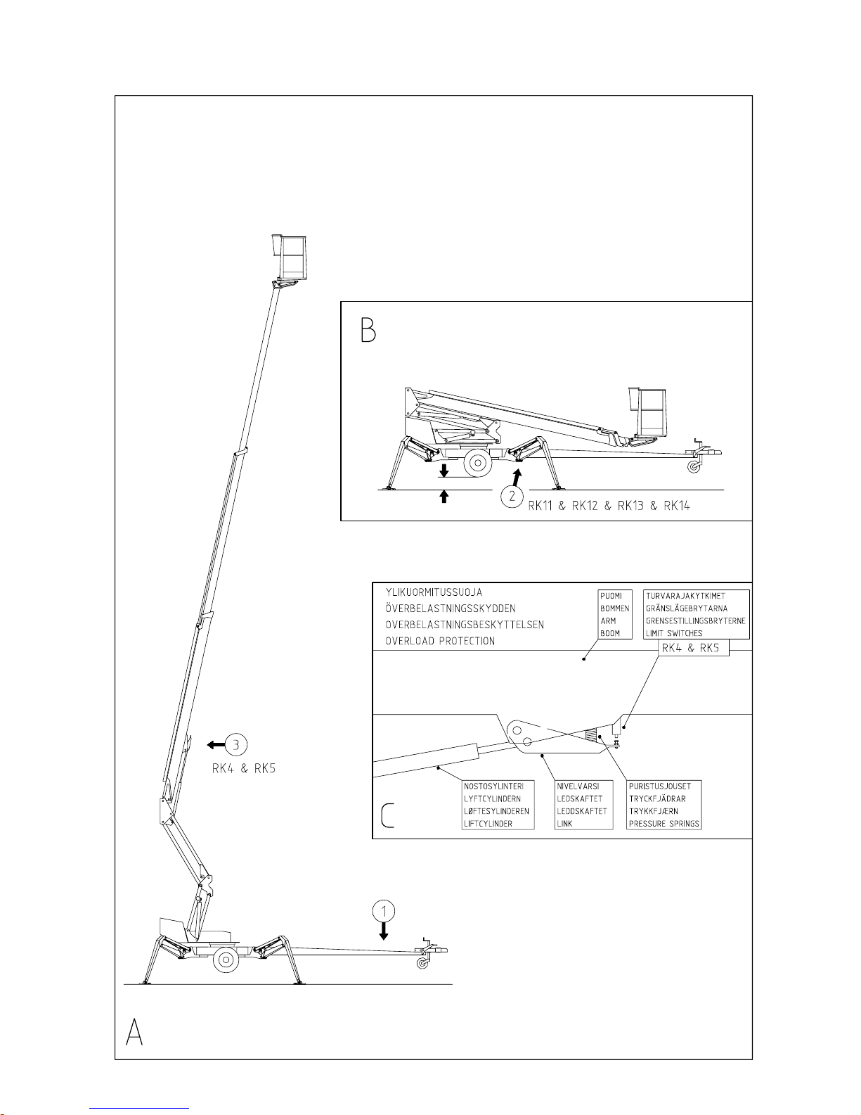
1. Lifting the boom (Fig. A)
The safety limit switch RK3 prevents the operation of the outriggers and the driving device when the
boom does not rest on the transport support.
The switch is located on the tow-bar at the transport support.
2. Support outriggers (Fig. B)
All the lift’s support outriggers must be in the support position before the boom is lifted. Make sure that
the wheels are off the ground.
The safety limit switches RK11, RK12, RK13 ja RK14 are located on the support outriggers.
3. Outreach range and overload protection switch (Figs. A and C)
The safety limit switches prevent overloading of the lift. At a predetermined position the outreach limit
switch RK4 stops extension of the telescope and lowering of the boom.
The overload limit switch RK5 backs up if the RK4 for some reason does not work.
The red light flashes and the buzzer buzzes as the RK4 stops the movement. When the red light is on,
the lift can be operated in the direction where it stays inside the allowed outreach area.
The overload limit switch RK5 backs up the operation of the RK4 and, at the same time, switches the
buzzer and the light signal on the platform to operate at a higher frequency.
4. As the emergency stop button is depressed all movements stop and the power unit is turned off.
The emergency stop pushbutton must be pulled up before starting the power unit.
Check operation of the safety devices.
DINO 260XTD
18
9 OPERATING CONTROLS
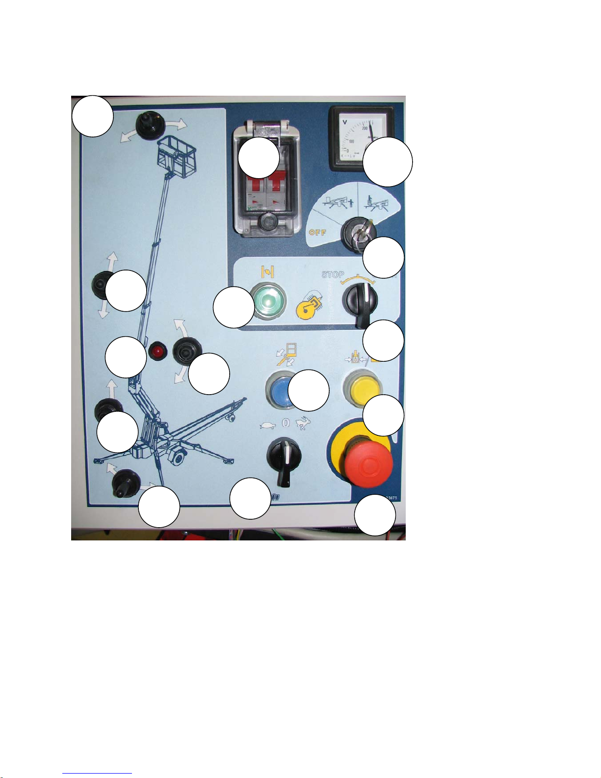
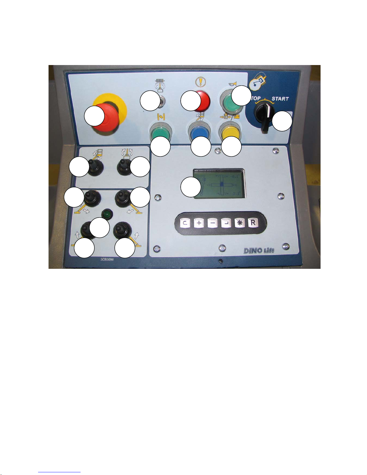
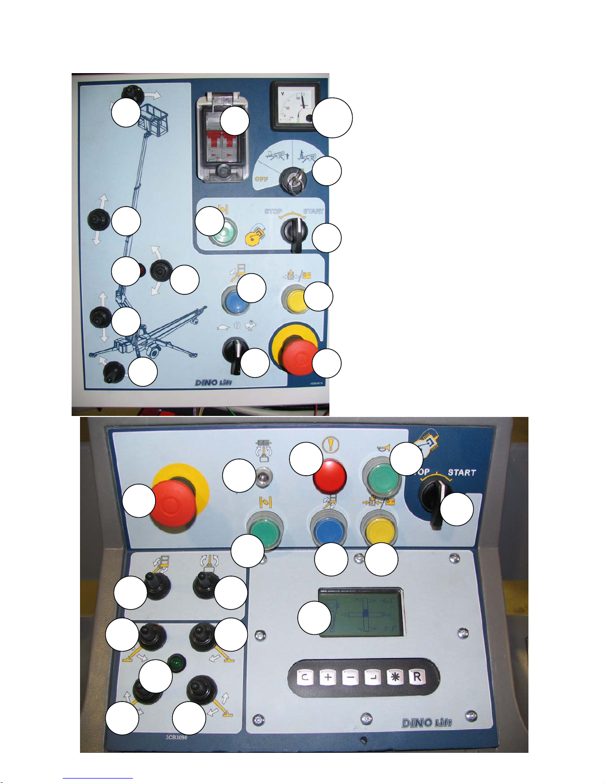
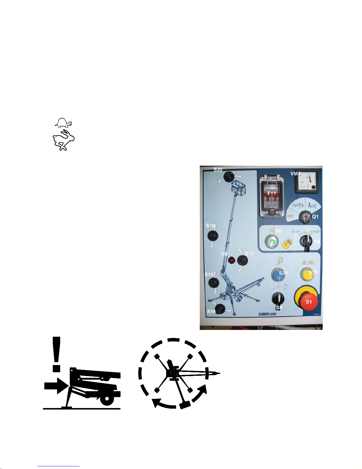
9.1 OPERATING CONTROLS ON THE CHASSIS CONTROL PANEL
F11 Fuse for the socket outlet on the platform
H8 Signal light for the outreach control safety limit switch
Q1 Selector switch for the operating location
S1 Emergency stop button
S6 Start and stop switches for the combustion engine
S8 Switch for selecting the movement speed of the boom
S9 Choke button for the combustion engine
S11 Start button for the emergency descent motor
S16 Turning the boom to the right and to the left
S17 Lifting and lowering the boom
S18 Retracting and extending the telescope
S19 Lifting and lowering the articulated arms
S20 Levelling the platform to the front and to the rear
VM1 Voltage meter for the mains current
S20
S18
S17
Q1
VM1
F11
S8
S6
S16
S19
H8
S9
S11
S31
S1
DINO 260XTD
19
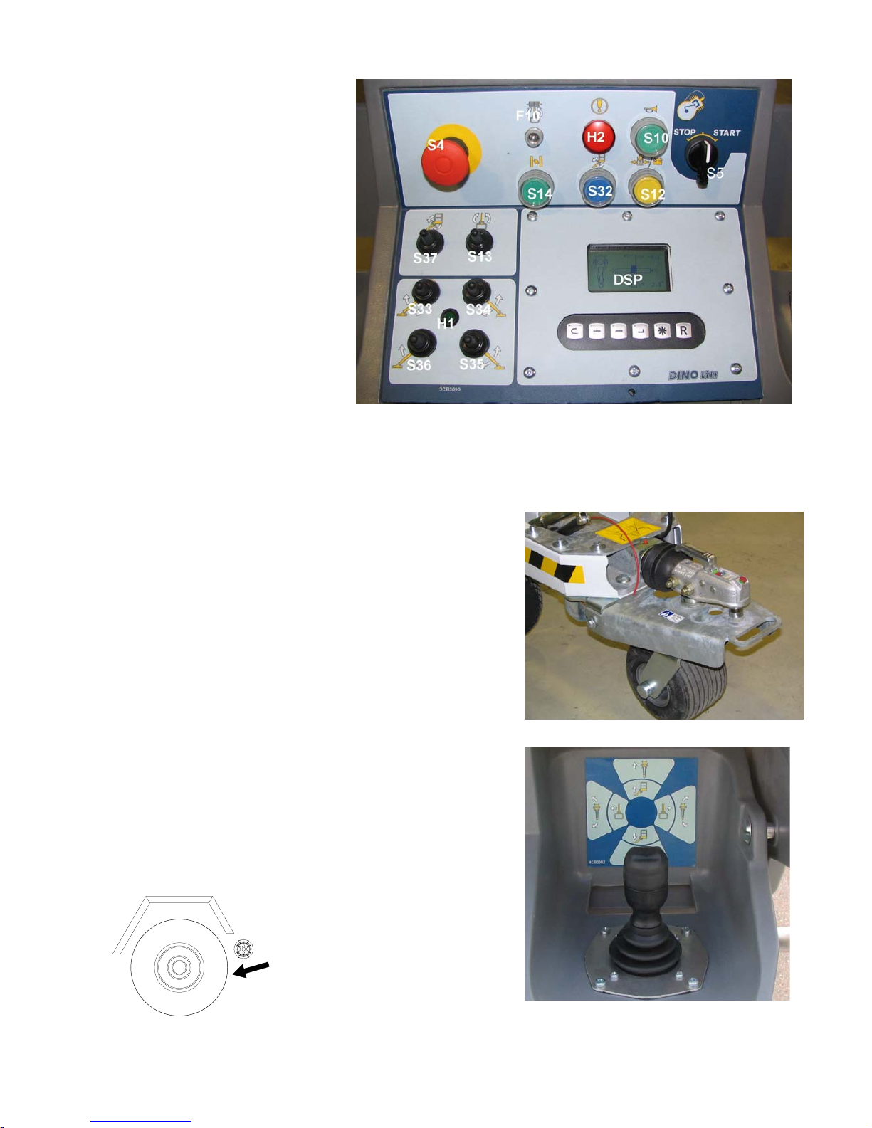
9.2 OPERATING CONTROLS ON THE PLATFORM
Close the cover of the chassis control panel before operating the platform controls.
DSP Display
H1 Signal light for the outrigger limit switches
H2 Alarm signal light
F10 Automatic fuse for turning the platform
S5 Start and stop switches for the combustion engine
S4 Emergency stop button
S10 Pushbutton for the sound signal
S12 Operating switch for the emergency descent system
S13 Turning the platform to the left and to the right
S14 Control switch for the combustion engine choke
S33 Lifting and lowering the support outrigger 1
S34 Lifting and lowering the support outrigger 2
S35 Lifting and lowering the support outrigger 3
S36 Lifting and lowering the support outrigger 4
S37 Levelling the platform to the front and to the rear
S36
S33
S35
S32
S14
S4
S37
S13
S34
S10
S5
H2
DSP
H1
S12
F10
DINO 260XTD
20
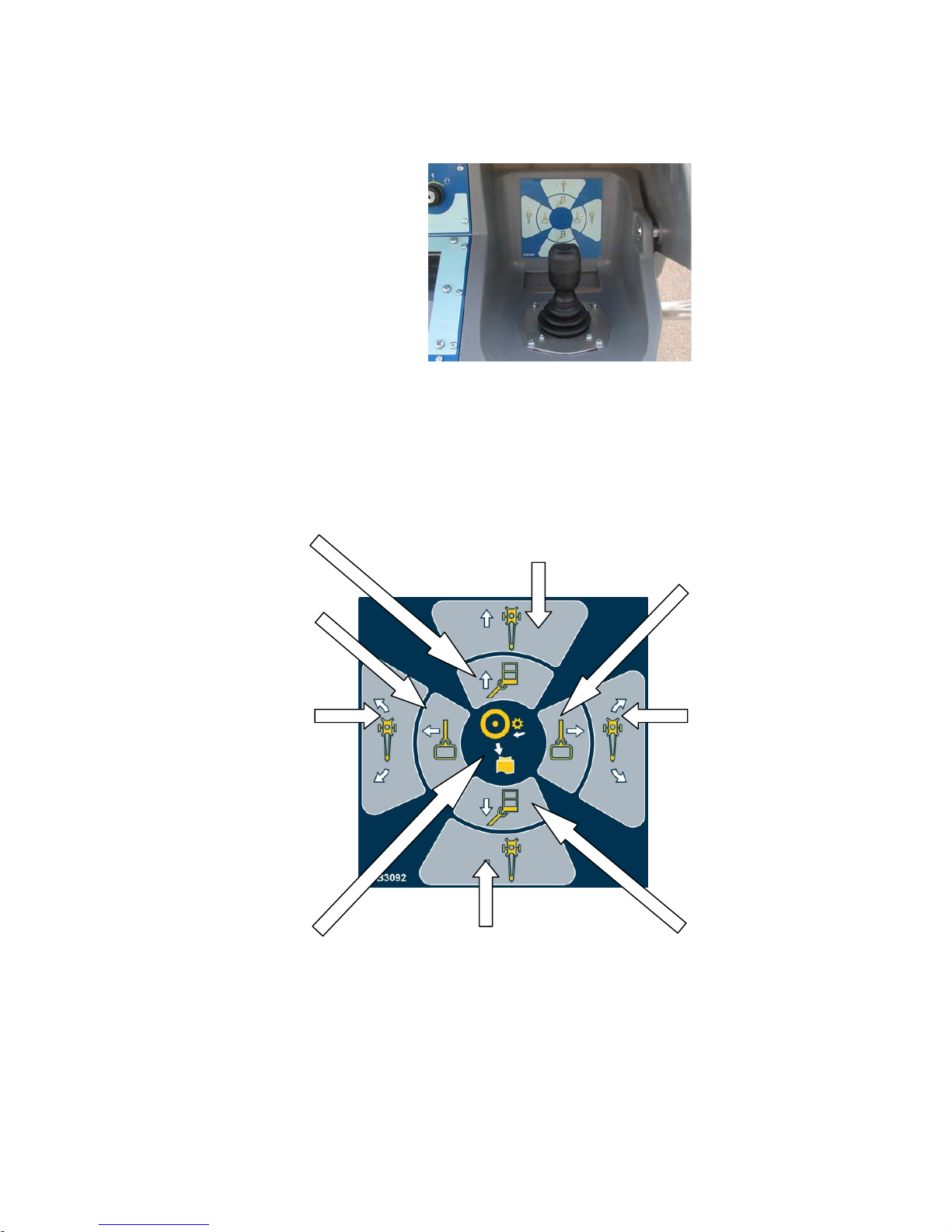
17. Control lever JSR (right)
Boom up Driving to the front
Turning the boom to
the left
Turning the
boom to the
right
Curving to the left, to
the front and rear
Curving to the
right, to the
front and rear
Switching on pressing
of the rollers (Pressing
is switched off from the
chassis)
Driving to the rear
Boom down
DINO 260XTD
21
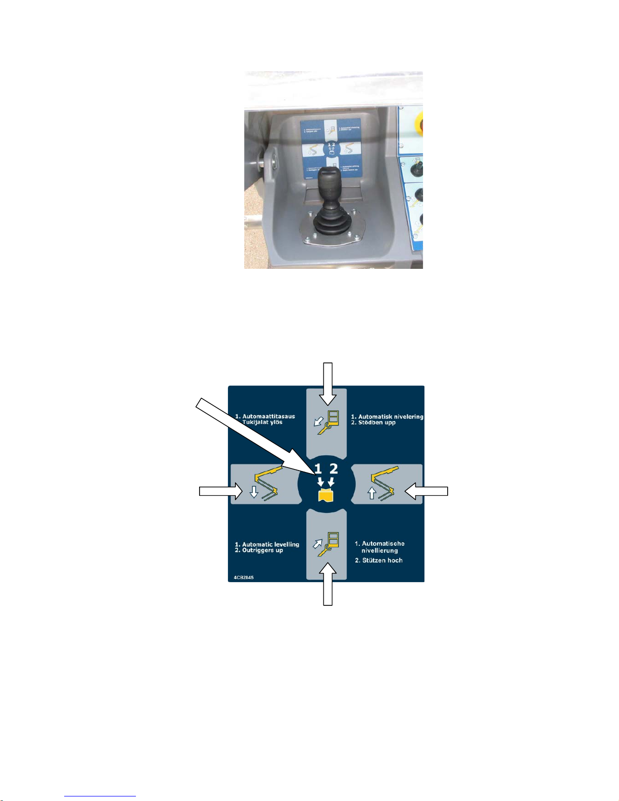
19. Control lever JSL (left)
Retracting the telescope
1. Automatic levelling
2. Outriggers up
(optional)
Lowering the
articulated arms
Raising the
articulated arms
Extending the telescope

DINO 260XTD
22
10 MEASURES TO BE TAKEN IN CASE OF EMERGENCY/AT RISK OF
LOSING THE STABILITY
Reduced stability can be caused by a fault in the lift, the wind or other lateral force, collapse of the
standing base or negligence in providing sufficient support. In most cases one sign of reduced stability
is the inclination of the lift.
WHEN AT RISK OF LOSING THE STABILITY
1. If there is time, try to find out the reason for the reduced stability and the direction of its effect.
Warn other people on the work site using the alarm signal.
2. If possible, reduce the load from the platform in a safe manner.
3. Reduce the outreach to the side by retracting the telescopic boom using the emergency descent
system. Avoid abrupt movements.
4. Turn the boom away from the danger zone, i.e. to a position where the stability of the lift is normal.
5. Lower the boom.
If the stability has been lost as a result of a fault in the lift, repair such a fault immediately.
Do not use the lift until the fault has been repaired and the condition of the lift has been verified.
IN CASE OF OVERLOADING
1. If there is time, try to find out the reason for the reduced stability and the direction of its effect.
Warn other people on the work site using the alarm signal.
2. If possible, reduce the load from the platform in a safe manner.
3. Reduce the outreach to the side by retracting the telescopic boom using the emergency descent
system.
4. The green light becomes illuminated when the overload situation is reset. After this the machine
may be operated normally.
IN CASE THE POWER SUPPLY IS INTERRUPTED (power unit/combustion engine)
1. Lower the boom using the emergency descent system (see point “Emergency descent system”).
2. Establish the reason why the energy supply was interrupted.
IN CASE OF MALFUNCTION, WHEN EVEN THE EMERGENCY DESCENT SYSTEM IS NOT
OPERATIONAL
1. If the emergency descent system does not operate, try to warn other personnel present on the site so
that they can call for help so that the power supply required for normal operation can be resumed or
make the emergency descent system operational by, for example, changing the battery so that the person
on the platform can be lowered safely.
DINO 260XTD
23
Always check the condition of the emergency descent system battery before putting the lift into
operation (see point "Using the chassis control panel").
11 START-UP
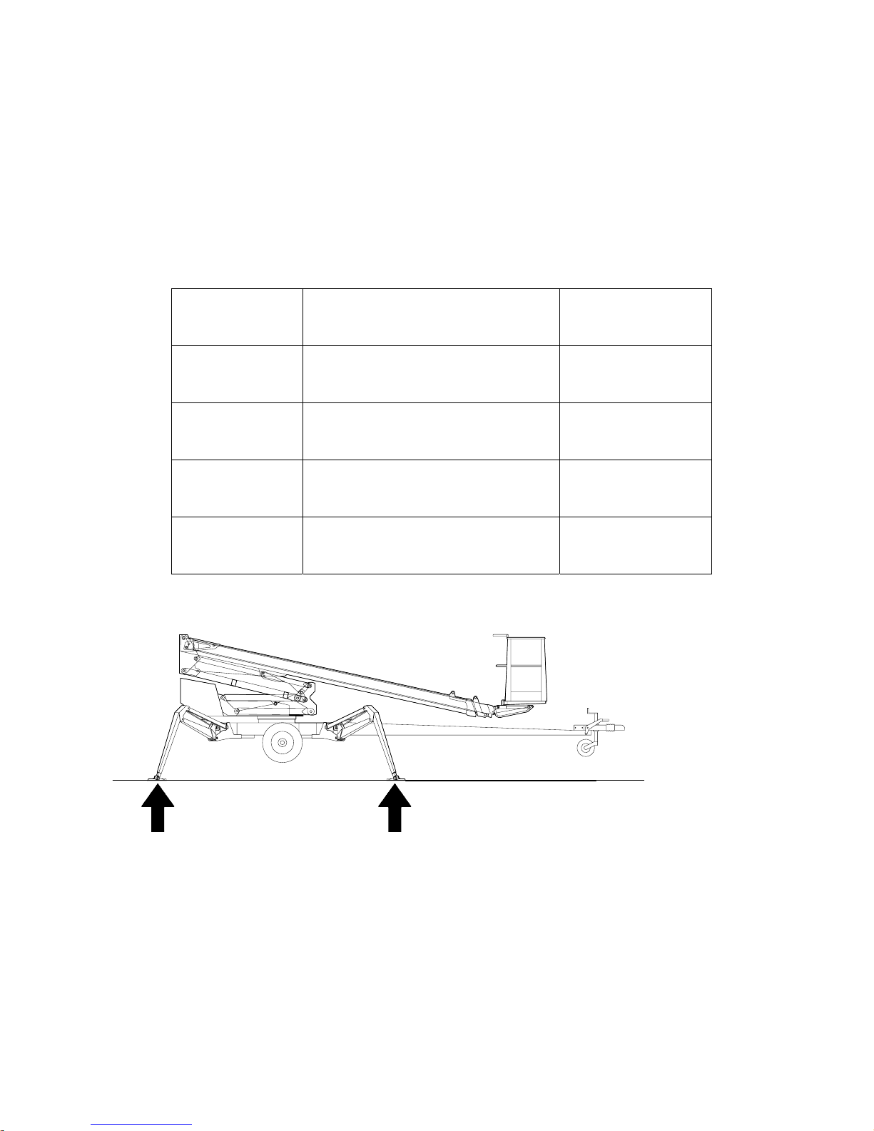
11.1 Ground stability
- make sure that the ground is even and hard enough to support the lift in a steady level position
Soil material Density Max. ground
pressure
P kg/cm²
Gravel High density 6
Medium density 4
Loose 2
Sand High density 5
Medium density 3
Loose 1,5
Fine sand High density 4
Medium density 2
Loose 1
Sand/ mud High density (very hard to work) 1,00
Medium density (hard to work) 0,50
Loose (easily worked) 0,25
- if the ground is soft, use sufficiently large and sturdy additional plates under the support outriggers
- observe the effect of ice, possible rain and inclination of the surface on the support (the support
outriggers must not slip on the surface)
- the operation is prohibited if the lift is not properly supported and in a level position
2. Drive or push the lift to the inspected lifting site
- apply the parking brake
- disconnect the lift from the towing vehicle
DINO 260XTD
24
S36
S33
S35
S32
S14
S4
S37
S13
S34
S10
S5
H2
DSP
H1
S12
F10
S20
S18
S17
Q1
VM1
F11
S8
S6
S16
S19
H8
S9
S11
S31
S1

DINO 260XTD
25
11.2 Starting the engine
At first, make sure that the main battery switch is switched on.
- The main switch is located on top of the chassis control panel.
Select the operating location using the switch Q1.
Check the condition of the battery to ensure operation of the emergency descent system. The emergency
descent unit must rotate at a fair speed as the emergency descent button is depressed.
A. POWERED BY AC-SUPPLY
- connect the mains cable to the power supply
- for maximum out of the electric motor the voltage must 230 VAC (-10%/ +6%), the frequency must
be 50 Hz (the length of the connecting cable has some effect)
- fuse 16 A
Starting the electric motor:
1. Operating the support outriggers from the chassis panel: turn the switch S47 to position 1 and select
any of the movement directions using the switches S41-S44 or S48 (see picture on the next page).
2. Operating the boom from the chassis panel: select the movement speed for the boom using the
switch S8 and, at the same time, select any direction of movement using the switches S16-S20.
3. Operating from the platform: as the foot pedal ís switched on and any direction of movement is
selected
The engine will stop 5 seconds after the movement stops
B. POWERED BY COMBUSTION ENGINE (POWER PACK)
- check that there is enough fuel in the tank.
- open the fuel cock and, as required, switch on the choke for the start using the separate pushbutton
(either the pushbutton S9 on the chassis panel or the switch S5 on the platform) and start the engine
using either the lever switch S6 on the chassis panel or the lever switch S5 on the platform
- adjust the engine speed (combustion engine) using the throttle lever
- If the battery is flat, start the unit by pulling the starter string and keeping the button in front of the
unit depressed. The key switch Q1 must be in the "operation from the chassis panel" position.
Pull the starter grip lightly until you feel resistance, then pull briskly. Keep the button depressed for
about 1 minute in order to recharge the battery.
Do not allow the starter grip to snap back against the engine.
- adjust the engine speed to halfway.
Let the combustion engine run for a sufficient period of time between operations because the battery
only recharges while the engine is running.
- The engine stops when the switch S5 or S6 is turned to the Stop position.
- Close the fuel cock when stopping the combustion engine.
Note! The fuel cock must be closed when the lift is towed.
For additional information concerning the operation of the combustion engine generator, please refer to
separate operating and service manual.
C. OPERATION WITH DIESEL ENGINE
- do not connect the mains cable (230 VAC)
Please refer to separate user manual for the diesel engine delivered with the lift for instructions
concerning the start-up of the engine, when the battery is empty.
Leave the combustion engine running between operations because the battery only recharges while the
engine is running.
To avoid damaging the electronics of the diesel engine; do not disconnect the mains current while the
diesel engine is running!
DINO 260XTD
26
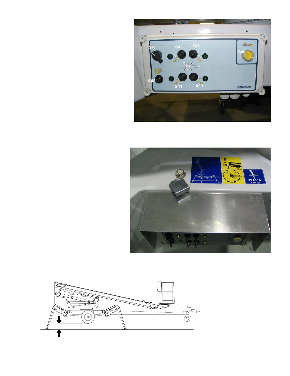
11.3 Operating the support outriggers from the chassis panel
The support outriggers may only be
operated, while the boom is resting on the
support.
The support outriggers are operated using
dedicated lever switches for each outrigger.
1. Turn the selector switch S47 to position
1 and keep it there as long as you
operate the selected movement.
2. Turn the lever switch, dedicated to this
outrigger, in the desired direction of
movement (as desired, all outriggers can
be operated simultaneously).
3. Lower the support outriggers in the
front.
4. Lower the rear support outriggers (Do
not damage the tow-bar jockey
wheel!)
Level the chassis using the outriggers in accordance with the level gauge.
5. The green signal light next to the operating lever for the outrigger will illuminate as soon as
sufficient force is exerted on the
outrigger.
Note! Illumination of the green signal
light does not necessarily mean that the
lift is on a level.
MAKE SURE THAT THE WHEELS
ARE CLEARLY OFF THE GROUND
- make sure all outriggers are firmly supported on the ground
DINO 260XTD
27
11.4 Operating the support outriggers from the platform panel
The support outriggers may only be operated, while the boom is resting on the support.
The support outriggers are operated using dedicated lever switches for each outrigger.
1. Press the foot pedal.
2. Turn the lever switch, dedicated to this outrigger, in the desired direction of movement (as
desired, all outriggers can be operated simultaneously).
3. Lower the support outriggers in the front.
4. Lower the rear support outriggers (Do not damage the tow-bar jockey wheel!)
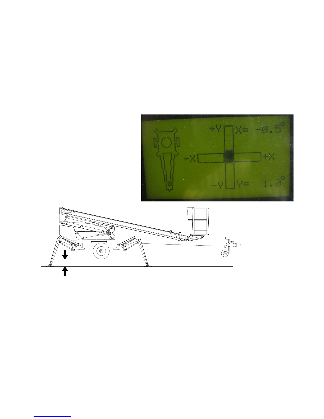
5. Level the lift using the outriggers.
a. the level position can be established by the columns on the display (DSP)
b. the numeric values X and Y indicate the tilt in degrees
c. check from the display that the inclination in directions X and Y is less than 0,3º
6. The green signal light H1 amid
the operating levers for the
outriggers will illuminate as soon
as sufficient force is exerted on
all outriggers.
Note! Illumination of the green signal
light does not necessarily mean that
the lift is on a level.
MAKE SURE THAT THE WHEELS
ARE CLEARLY OFF THE
GROUND
- make sure all outriggers are firmly supported on the ground
Automatic levelling (optional)
1. Press the foot pedal.
2. Depress the left-hand side of the rocker switch on the left joystick in order to balance the lift to a
level.
3. Continue the levelling until the movement stops.
4. Establish on the display that the inclination in directions X and Y is less than 0,3º.
Always check the level position of the lift.
Readjust manually, as necessary.
Lifting the outriggers to the transport position using the automatic levelling
5. Press the foot pedal.
DINO 260XTD
28
6. Depress the right-hand side of the rocker switch on the left joystick in order to lift the outriggers to
transport position.
11.5 Using the chassis control panel
Select the chassis panel using the selector switch (Q1) for the operating location
- start the combustion engine or the electric motor in accordance with the instructions
- select the speed using the switch S8 (keep the switch activated throughout the operation)
- the switch has three positions
- Position 0 - none of the movements operate
- - position - boom movements operate at low speed
- - position - boom movements operate at high speed
- the boom movements, controlled using the switches S16-S20, operate at selected speed
- test the operation of the emergency descent
system as follows:
1. lift the boom about 1-2 metres, extend the
telescope 1-2 metres and depress the emergency
stop button - the motor and the movement should
now stop
2. start the emergency descent power unit
(pushbutton S11), retract the telescope (lever
switch S18 or pushbutton S31) and lower the
boom (lever switch S17)
3. pull up the emergency stop button
The boom movements are noticeably slower when
the emergency descent system is used.
Note! If you have levelled the chassis of the lift ON A
GRADIENT turn around the boom carefully to
make sure that the turning device does not bang
against the support outriggers.
- lift the platform from the tow-bar and turn it to the side to enable its lowering
- extend the telescope as much as necessary to ensure safe entrance on the platform
DINO 260XTD
29
DO NOT DAMAGE THE TOW-BAR JOCKEY WHEEL!
11.6 Using the control panel
on the platform
- once the foot pedal is depressed,
the electric motor starts
automatically as any of the
movements is activated
- for operation powered by
combustion engine, start the
engine using the selector switch
S5
Adjust the engine speed to ¾ of
the maximum. The engine speed
affects the movement speed of
the lift
11.7 Driving device
The hydraulic driving device is intended for moving the lift
within the work area.
If the terrain is rough, use the remote control panel or a
towing vehicle.
Make sure the platform is in the transport position and the
outriggers are in the upper position.
Make sure that the mains cable is long enough to cover the
whole travel distance (power supply from mains).
Use the additional jockey wheel during transportation. The
wheel is located on the left-hand side behind the machine.
Operating the lift from the platform panel
- activate the foot pedal and press the driving device against
the wheel depressing the left face of the rocker switch on
the right-hand joystick (JSR)
The switching on can also be performed from the chassis
control panel by turning the lever switch S47 to position 1
and selecting the direction of movement for the rollers
using the switch S48. The disconnection can only be
performed from the chassis control panel using the switch
S48.
- release the parking brake
DINO 260XTD
30
- activate the foot pedal and drive the unit using the right-hand joystick (JSR) (see the operating
diagram in point “Using the control panel on the platform”)
- do not drive the jockey wheel into obstacles or potholes
- after the driving apply the parking brake
- do not disconnect the driving device from the tyre until having
engaged the handbrake from the chassis control panel
Driving using the remote control panel
- the control panel is located on top of the chassis control panel, behind the machine
- press the rollers against the tyres as instructed (see point “Driving device”)
- the remote control panel has arrow keys for driving to the front and rear, turning to the right and left
as well a pushbutton for emergency stop
REMEMBER THE HANDBRAKE!
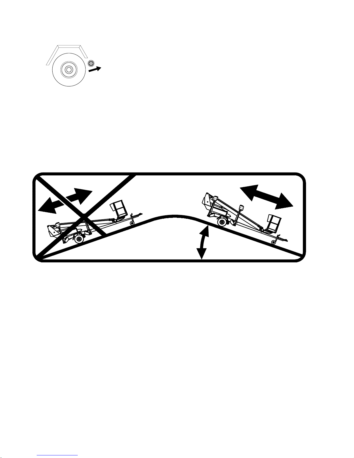
WARNINGS.
1. Do not drive downhill with the driving device if the inclination of the surface is more than 5 per
cent, i.e., more than 1/20 (corresponding to a descent of 0.5 m over a distance of 10 m). If the
surface gradient is greater than this, you may lose control of the device.
2. When driving on a slope, the tow-bar must always point towards the descent.
Never drive with the driving device with the tow-bar pointing towards the ascent.
3. Always place chocks under the wheels before disconnecting the device from the towing vehicle.
4. Always apply the handbrake before disconnecting the device from the towing vehicle.
Only use the handbrake as a parking brake or for emergency stopping.
5. Never leave the lift on a slope being supported only by the self-braking action of the driving device.
6. When transferring the lift using the driving device:
- take care not to allow the wheel to roll over your foot
- look out for sudden sideways movements of the tow-bar
- be careful not to cause danger to other people and the environment
7. Do not move the device on a slope using only hand-power. You may lose control over it and cause
an injury.
8. Never park a vehicle combination on a slope.
maks. 5 %
 Loading...