

Dino lift DINO 185XTS Operating Instructions Manual
®
DINO
OPERATING INSTRUCTIONS
185XTS
Raikkolantie 145
FI-32210 LOIMAA
T. +358 2 762 5900
F. +358 2 762 7160
dino@dinolift.com
www.dinolift.com
Dealer: Manufacturer

2

ORIGINAL OPERATING INSTRUCTIONS
VALID FROM SERIAL NUMBER 540016
3

TABLE OF CONTENTS
OPERATION AND SAFETY ................................................................................................ 7
1. EU DECLARATION OF CONFORMITY ..................................................................... 7
2. REACH DIAGRAM ..................................................................................................... 8
3. DIMENSION DRAWING ............................................................................................ 9
4. TECHNICAL SPECIFICATION .................................................................................10
4.1 Example of the machine’s nameplate ................................................................10
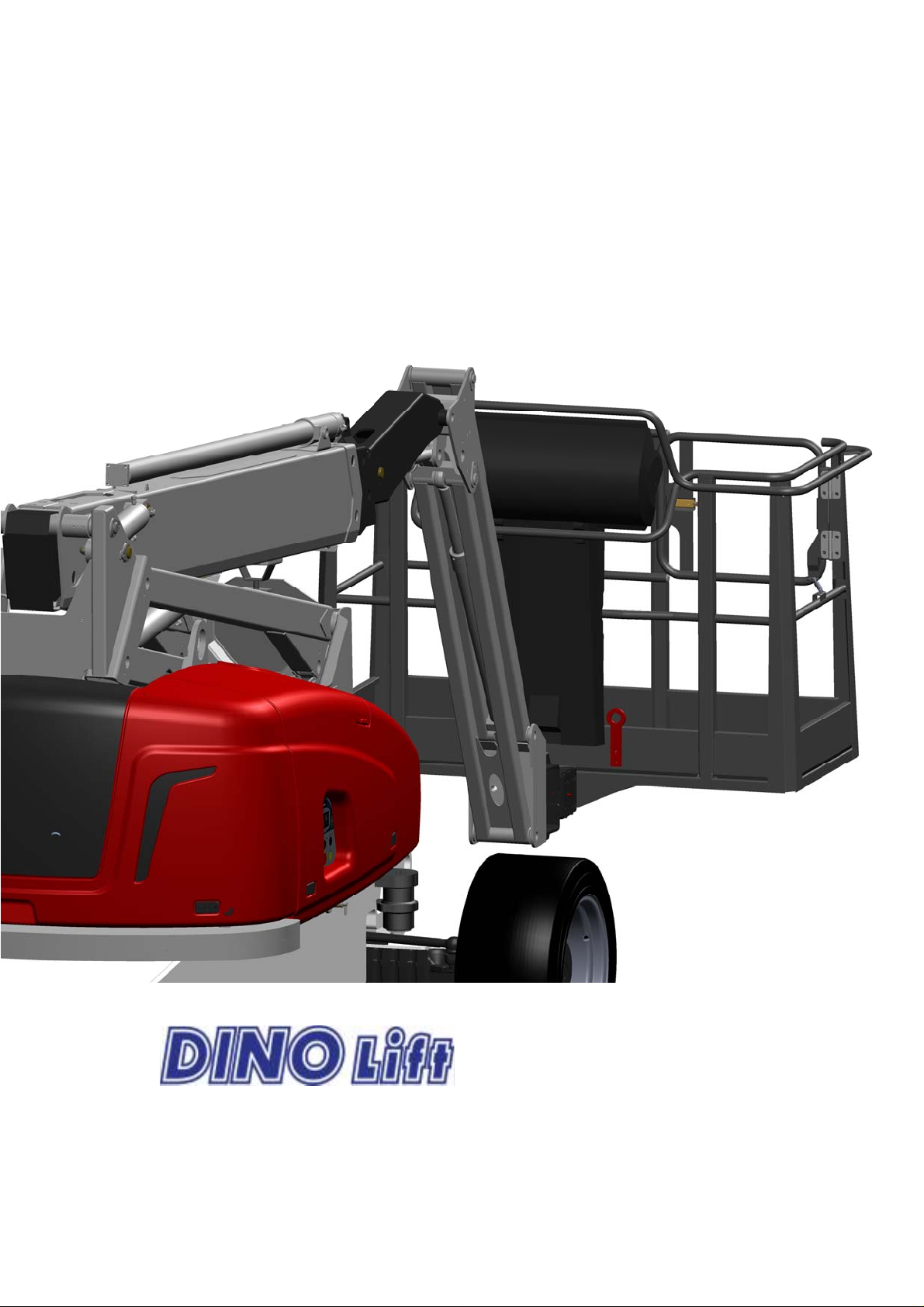
4.2 General description of the machine ...................................................................11
4.3 Description of the machine’s intended use ........................................................12
5. GENERAL SAFETY REGULATIONS ........................................................................12
6. INSPECTIONS ..........................................................................................................16
7. DAILY INSPECTION (START-UP INSPECTION) .....................................................17
8. WORKSITE INSPECTION ........................................................................................19
9. OPERATION OF THE SAFETY DEVICES ................................................................20
9.1 Lifting the boom/ articulated arms (RK3) ...........................................................20
9.2 Boom extensions retracted (RK8) ......................................................................20
9.3 Emergency stop buttons (S1 and S4) ................................................................20
9.4 Platform load control (MRV)...............................................................................21
9.5 inclination sensors RK30a and RK30b...............................................................23
10. OPERATING CONTROLS .....................................................................................24
10.1 LCB – CONTROLS IN THE CHASSIS PANEL – XTS ......................................24
10.2 UCB – OPERATING CONTROLS ON THE PLATFORM – XTS .......................25
11. MEASURES TO BE TAKEN IN CASE OF EMERGENCY/AT RISK OF LOSING
THE STABILITY ...............................................................................................................27
12. STARTING UP ......................................................................................................28
12.1 Familiarise yourself with the machine and these instructions ............................28
12.2 Starting the engine .............................................................................................28
12.2.1 From the chassis control panel LCB ...........................................................28
12.2.2 From the platform control panel UCB .........................................................29
12.3 Transferring, driving and steering ......................................................................31
12.3.1 Driving to the front and to the rear ..............................................................31
12.3.2 Steering ......................................................................................................32
12.3.3 Using the differential lock ............................................................................32
12.4 Operating the boom ...........................................................................................32
12.4.1 Operating the boom from the platform control centre UCB .........................33
12.4.2 Operating the boom from the chassis control centre LCB ..........................35
12.5 Socket outlets on the platform. ..........................................................................36
12.6 General driving instructions ...............................................................................36
13. EMERGENCY DESCENT SYSTEM ......................................................................38
13.1 General information ...........................................................................................38
13.2 Using the emergency descent system ...............................................................39
13.2.1 From the chassis control centre LCB ..........................................................39
13.2.2 Emergency descent from the platform control panel UCB ..........................39
13.3 Testing the operation of the emergency descent system ...................................39
14. SPECIAL INSTRUCTIONS FOR WINTER USE ....................................................40
15. MEASURES TO BE TAKEN AT THE END OF THE WORKING DAY .....................40
16. PREPARING THE LIFT FOR TRANSPORT ..........................................................41
4

16.1 Transporting on flatbed of a vehicle ...................................................................41
16.2 Lifting .................................................................................................................42
16.3 Towing ...............................................................................................................43
17. NOTES ..................................................................................................................45
SERVICE AND MAINTENANCE .........................................................................................46
18. INSTRUCTIONS FOR SERVICE AND MAINTENANCE ........................................46
18.1 General service instructions ...............................................................................46
18.2 Service and inspection instructions ....................................................................47
19. LUBRICATION INSTRUCTIONS ...........................................................................49
19.1 Lubrication table ................................................................................................50
20. LONG-TERM STORAGE ......................................................................................51
21. AXLES AND TYRES ..............................................................................................51
21.1 Tightening torques of the bolts: ..........................................................................51
21.2 Tyres ..................................................................................................................51
21.3 Axles ..................................................................................................................52
21.3.1 Checking the levels/change of transmission oil ..........................................52
22. LOAD HOLDING AND LOAD REGULATION VALVES ..........................................53
22.1 Location of the load regulation valves ................................................................53
22.2 Checking the operation of the load regulation valves ........................................54
22.3 Service instructions for the load regulation valves .............................................55
23. LEVELLING SYSTEM OF THE WORK PLATFORM..............................................56
24. CALIBRATION OF THE CONTROL SENSOR FOR THE PLATFORM LOAD ........57
25. DPF- DIESEL PARTICLE FILTER (OPTION) ........................................................58
26. REGULAR SERVICING.........................................................................................59
26.1 Schedule for regular servicing ...........................................................................59
26.2 Schedule for regular servicing ...........................................................................59
26.2.1 Cleaning the lift ...........................................................................................59
26.2.2 Changing the hydraulic oil and the filters ....................................................60
26.2.3 Hydraulic hoses, connectors and pipes ......................................................62
26.2.4 Chassis, transmission, axles and wheels ...................................................62
26.2.5 Checking the boom cylinders ......................................................................63
26.2.6 Inspecting the boom and the chassis .........................................................64
26.2.7 Checking the operation of the load control system for the platform (MRV) .68
26.2.8 Measuring the pressure ..............................................................................70
26.2.9 Check the operating controls on the work platform (UCB) and in the lower
control centre (LCB) ..................................................................................................71
26.2.10 Warning stickers and instructions ...........................................................71
26.2.11 Deutz (D 2011 L03 i) Diesel power unit ...................................................71
26.2.12 Check the anti-corrosive/paint coat .........................................................73
26.2.13 Test run in accordance with the loading instructions ...............................73
26.2.14 Draw up a protocol of the service ............................................................73
27. TEST LOADING INSTRUCTIONS FOR REGULAR INSPECTION ........................74
28. INSPECTION INSTRUCTIONS .............................................................................76
28.1 FIRST INSPECTION .........................................................................................76
28.1.1 Sample of inspection protocol for the access platform ...............................77
28.2 MONTHLY INSPECTION (MAINTENANCE INSPECTION) ..............................79
28.3 ANNUAL INSPECTION (REGULAR INSPECTION) ..........................................80
28.3.1 Perform the measures of the daily and monthly inspection ........................80
28.3.2 thoroughly inspect the hydraulic system .....................................................80
5

28.3.3 Thorough inspection of the electric system .................................................82
28.3.4 Thorough inspection of the steel structures ................................................83
28.4 EXTRAORDINARY INSPECTION .....................................................................85
29. FAULT FINDING ...................................................................................................86
29.1 Error codes of the electric control system ..........................................................86
29.1.1 Error codes of the control system for the boom ..........................................86
29.1.2 Error codes of the control system for the transmission ...............................87
29.2 Fault finding table ..............................................................................................88
30. DIAGRAMS AND COMPONENTS ........................................................................92
30.1 ELECTRIC SAFETY COMPONENTS 540001 ...............................................92
30.1.1 CHASSIS CONTROL CENTRE (LCB), RELAYS .......................................92
30.1.2 CHASSIS CONTROL CENTRE (LCB), SWITCHES ...................................92
30.1.3 CONTROL CENTRE ON PLATFORM (UCB), SWITCHES AND SIGNAL
LIGHTS 92
30.1.4 LIMIT SWITCHES AND SAFETY DEVICES ..............................................93
30.1.5 OTHER MARKINGS ...................................................................................94
30.2 DINO 185 XTC ELECTRIC COMPONENTS 540003 .....................................95
30.3 ELECTRIC DIAGRAMS 540003 .....................................................................97
30.4 HYDRAULIC COMPONENTS 540003 ......................................................... 117
30.5 HYDRAULIC DIAGRAMS 540003 ................................................................ 118
31. NOTES ................................................................................................................ 121
6

OPERATION AND SAFETY
1. EU DECLARATION OF CONFORMITY
Manufacturer:
Dinolift Oy
Raikkolantie 145
FI-32210 Loimaa, FINLAND
which has authorised Chief Engineer Mr. Seppo Kopu, Dinolift Oy, Raikkolantie 145, 32210
Loimaa, Finland to draw up the Technical Construction File
declares that
DINO 185XTS Access Platform no YGC185XTSD05400XX
is in conformity with the provisions of Machinery Directive 2006/42/EC as amended and
with national implementing legislation and also fulfils the requirements of the following EEC
directives: Low Voltage Directive (2006/95/EC), directive (2000/14/EC), and EMC Directive
(2004/108/EC).
Conformity assessment procedure followed: 2000/14/EC, Annex V: Internal control of
production.
Measured sound power level Lwa ( 95,5 + 1,5 ) 97 dB
Quaranteed sound power level Lwa 97 + 0,5 dB
Notified body nr. 0044,
RWTÜV
Postfach 10 32 61
DE-45032 Essen
has granted the certificate no. TÜV 44 205 12 399100
In designing the machine, the following harmonized standards have been applied:
SFS-EN 280/A1+A2; SFS-EN 60204-1/A1
Loimaa 22.05.2013
(place) (date)
-----------------------------------------
(signature)
Seppo Kopu, Chief Engineer
(name in block letters, position)
7
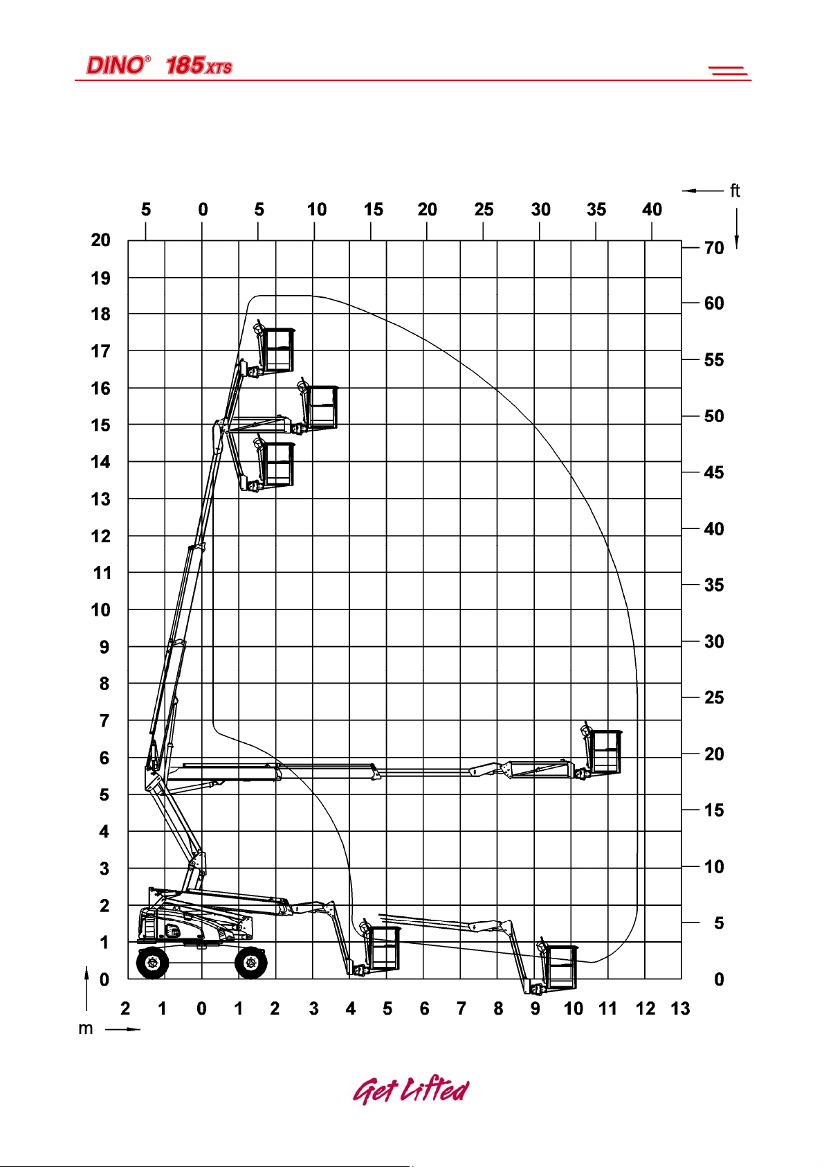
2. REACH DIAGRAM
8
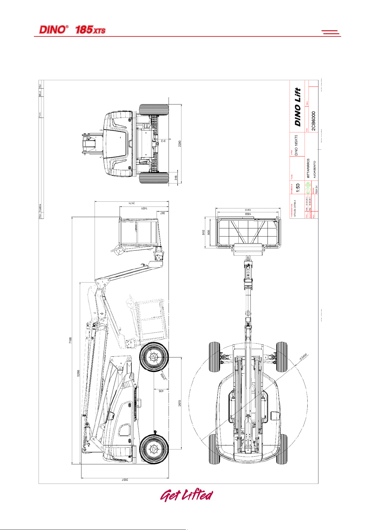
3. DIMENSION DRAWING
9
4. TECHNICAL SPECIFICATION
Max. working height (18.5 m)
Max. platform height (16.5 m)
Max. outreach (11.7 m)
Boom rotation continuous
Platform rotation 180°
Work area refer to the reach diagram
Swing radius (1.75 m)
Transport width (2.29 m)
Transport length driving / transportation 7.17m / 5.27m
Transport height (2.56 m)
Weight 8000 kg
Fuel tank capacity 100 litres
Fuel left for 20 more hours
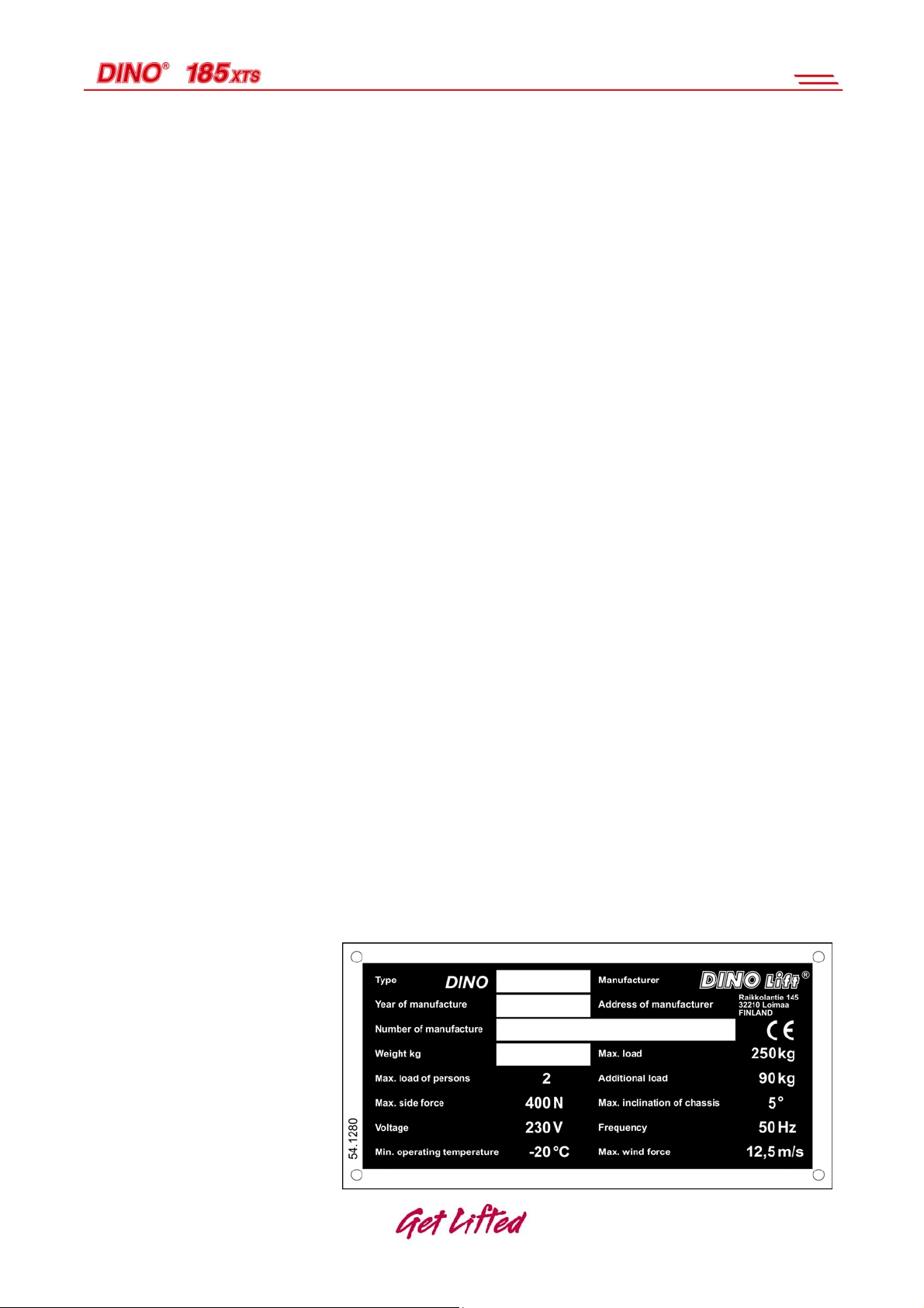
Max. allowed load on platform 250kg
Max. number of persons + additional load 2 persons + 90 kg
Max. allowed sideways load (caused by persons) 400 N
Max. lateral inclination of chassis ±5°
Max. wind speed during operation 12,5 m/s
Min. ambient temperature when working -20 °C
Tyres IN315/55D20. (Foam filling)
Maximum possible tyre load 35.000 N (3.570 kg)
Max. ground pressure 3.2 kg/cm2
Platform size 0.8 x 1.8 m
Driving speed high/low 1 km/h / 6 km/h
Gradeability 45 %
Power supply: DIESEL
Combustion engine (Deutz D2011 L03 i) 36.3 kW (48 h.p.)
Sound pressure level 98 dB
Socket outlets on the platform 230V / 50Hz / 16A
Filling capacity of the hydraulic oil tank: 86 litres
Pressure of the hydraulic system:
Drive hydraulics: 400 bar
Boom system hydraulics: 210 bar
4.1 Example of the machine’s nameplate
10
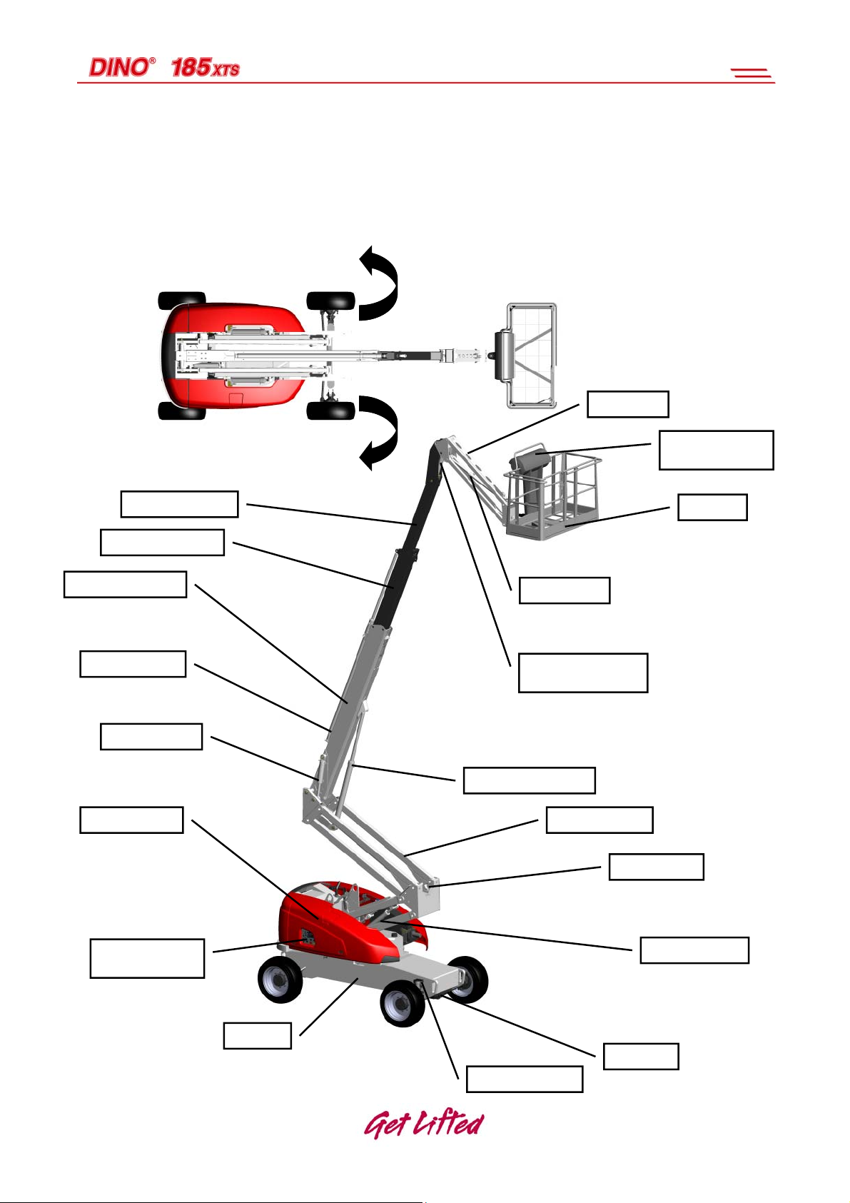
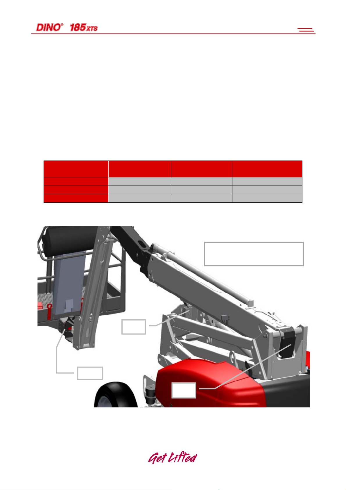
4.2 General description of the machine
The denominations of the machine’s essential parts and concepts,
which are used later in these instructions, are described on this
page.
Left
Turning
counter-clockwise
Right Turning
clockwise
Boom extension 3
Boom extension 2
Boom extension 1
Boom cylinder
Mastercylinder
Turning device
Chassis control
centre (LCB)
Chassis
Jib
Platform control
centre (UCB)
Platform
Jib cylinder
Levelling cylinder of
platform
Lifting cylinder
Articulated arms
Boom support
Arm cylinder
Axle
Locking cylinder
11

4.3 Description of the machine’s intended use
The Dino 185 XTS Access Platform is exclusively intended for lifting and
transferring people and tools and acting as a work platform to the limit of its
load-bearing capacity and reach (see Technical specifications and Reach
diagram).
The intended use also covers:
- Following all the instructions in the Operating Instructions
- Performance of the inspections and maintenance operations
5. GENERAL SAFETY REGULATIONS
Make yourself familiar with these operating instructions before using the lift!
Keep these operating instructions carefully with the lift in the place reserved for them.
Make sure that all users of the lift are familiar with these instructions.
Advise new users and strictly follow all instructions given by the manufacturer.
Make sure you clearly understand all instructions relating to the operational safety of
the lift.
Only specially trained personnel with authorisation in writing from their employer and
who have good familiarity with the device and are at least 18-years old are allowed
to operate the lift
The max. allowed load on the platform is two (2) persons and at maximum ninety
(90) kg of additional load, however, the total load must not exceed two hundred fifty
(250) kg.
.
The work platform may only be used, whilst the chassis is well supported, i.e. the
tyres are supported on sufficiently firm and level ground. Refer to the Technical
specification and the decals affixed to the machine for max. load on the tyres.
Take into account the gradient of the terrain, when selecting the worksite.
The weather conditions, such as wind, visibility and rain, must always be taken into
account so that these factors will not adversely affect the safe performance of the
lifting operations.
The lift must not be used if the temperature drops below -20°C or the wind speed
exceeds 12.5 m/s.
Protect your hearing when you operate the lift from the chassis control panel (LCB)
(91 dB).
While on the platform, always wear the safety harness and fix it to the prescribed
fixing loops.
12

Do not use ladders, steps or other similar equipment on the platform.
Never throw any objects from the platform.
The lift must not be used for transferring goods or persons between different floors or
working levels.
Never disable the operation of any safety device.
Always make sure before lowering the platform that the area on the underside is
clear of any obstructions.
Avoid damaging the platform by lowering it on the ground or bringing it in contact
with any structures.
When working in busy areas the operating range of the lift must be clearly marked by
using either warning lights or fencing.
Always exercise utmost caution while driving with the platform raised.
Keep the lift free of any dirt which may impair safe operation and impede the
inspection of the structures.
The device must be serviced and inspected regularly.
Only skilled persons familiar with servicing and repair instructions are allowed to
carry out servicing and repair work.
It is strictly prohibited to use a lift which is out of order.
The lift must not be used when located on the bed of a lorry, on a trailer, on board a
vessel or in any other similar location.
Never load the platform while in the upper position.
Never exceed the maximum load of the work platform (250 kg).
The lift MUST NOT be used as a crane.
Before starting the operation, make sure that the turning device's tail overhang can
spin around without obstruction.
Always check the level position of the machine. The warning light (H17)
on the platform indicates that the inclination is too great.
Ensure that the lift cannot slide while on a gradient.
Check that there are no outsiders in the work area.
13

Stepping on or off the platform in motion is prohibited.
Familiarise yourself with the terrain before starting the operation. The max. allowed
inclination of 20 ° must not be exceeded while transferring the lift. If the inclination is
more than 5° during the transfer, the work platform must be in the transport position.
Before starting the operation, always ensure that the safety devices and the
emergency descent system are working properly.
Do not take tools/material of large surface area onto the platform. The increase in
wind load may jeopardize the stability of the device.
Always keep the lift free from dirt, snow and ice.
Ensure that the lift is inspected and serviced, before use.
Never use a defective lift.
Never use a lift alone. Make sure that there is always someone on the ground, who
can call for help in case of an emergency.
14
The device must not be altered without the manufacturer’s consent nor
used under conditions that do not meet the requirements set by the
manufacturer.
The operator must be given instructions and consent from the
manufacturer for all such specific work methods or conditions that the
manufacturer has not explicitly defined.
Beware of the live aerial power lines in the area – observe the minimum
safety distances:
100 – 400 V hanging
100 – 400 V open-wire
Weight Min. distance below
(m)
spiral cable
cable
6 – 45 kV 2 3
110 kV 3 5
220 kV 4 5
400 kV 5 5
0.5 0.5
2 2
Min. distance at the
side (m)
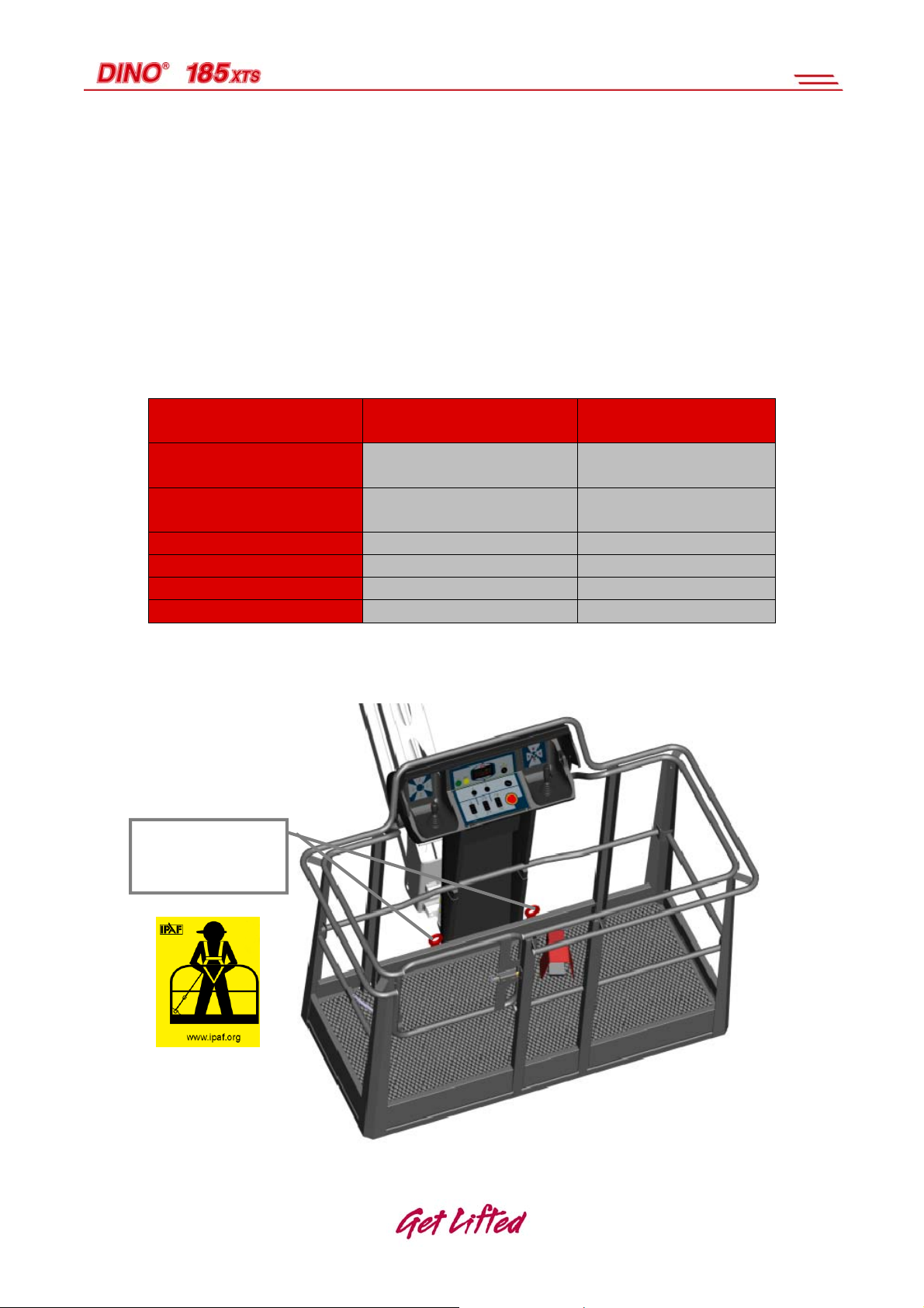
Use a safety harness while on the platform.
Fixing points for
the safety
harness.
15

6. INSPECTIONS
A thorough inspection of the lift must be carried out at least once every twelve (12) months.
The inspection shall be carried out by a technically trained person who is familiar with the
operation and structure of the lift.
Draw up a protocol of the inspections and always keep it with the unit stored in the space
reserved for it.
Carry out the inspections regularly basis throughout the service life of the lift.
The inspection must be carried out within twelve (12) months off the first or previous
inspection.
If the lift is used under extreme conditions, intervals between the inspections shall be
reduced.
The overall operating condition of the lift as well as the condition of the safety-related
control devices shall be established in the regular inspections. Particular attention shall be
paid to changes which affect the operational safety.
In connection with the regular inspection, it shall be established to what extent the lessons
and practical experience gained from the previous inspection can be implemented for even
better safety.
NOTE! National legislation must be followed first of all!
Regular inspections and service measures are described more thoroughly in the chapter
“Service- and maintenance”.
16

7. DAILY INSPECTION (START-UP INSPECTION)
To be always performed at a new worksite and in the beginning of every working day.
The inspection is performed by the user. In the inspection attention shall be paid to
the following issues:
Establish the load-bearing capacity of the ground (see point “General safety
regulations”).
Verify the standing stability of the lift.
Control the due operation of the indicator for level position.
Test the operation of the emergency stop system both from the platform and the
chassis control panels.
Test the operation of the emergency descent system both from the platform and the
chassis control panels (see point “Emergency descent system”).
Testing the sound signal and the signal lights.
Check that the lights and reflectors are in order and clean, and the warning and
instruction decals are clean.
Check the condition of the operating controls and test all the work movements.
Check the condition of the access routes, the platform gate and the handrails.
Check the operation of the safety devices.
Check the operation of the limit switches that prevent the movements of the boom.
Check the system for oil leaks.
Check the structures visually.
Observe the location of nearby power lines and overhead obstacles.
Inspect visually the tread of the tyres.
Cleanliness of the pre-filter/water trap of the fuel. Drain off the accumulated water
from the tap screw.
Check the element of the Diesel engine cooler for cleanliness.
17

Check the operation of the control system for platform load. Check that, when there
is no load on the platform, both the green and the yellow LED indicators are
illuminated (see point “Operation of the safety devices”).
Check the element of the Diesel engine cooler for cleanliness
18
8. WORKSITE INSPECTION
1. General information
- Is the lift suited for the intended job?
- Is the performance of the lift sufficient for the job? (reach, loadability etc.)
- Is the position of the lift safe?
- Is the terrain suitable for using the lift (evenness and load-bearing capacity)?
- Is the lighting on the worksite sufficient?
Permissible ground pressure for different soil types
Soil material Density Permissible ground
pressure kg / cm ²
Gravel
Sand
Fine sand
Sand/ mud
High density
Medium density
Loose
High density
Medium density
Loose
High density
Medium density
Loose
Fixed
Tough
Soft
6
4
2
5
3
1.5
4
2
1
1
0.5
0.25
2. Documents
- Are the Operation and Service Instructions for this lift present? (Manufacturer’s
instructions)
- Are inspections and servicing carried out in accordance with the instructions and
have the defects affecting the safety been checked as repaired?
(Inspection protocols)
3. Structure (Visual inspection and operational test)
- General condition of the lift
- Operation and protection of the controls
- Emergency stop, signal horn and limit switches
- Electrical appliances and wiring
- Oil leaks
- Load markings and signs
4. Operator
- Is the operator old enough?
- Has the operator received the required training?
5. Special issues on the worksite
- Are there any additional regulations relevant to the worksite or the work?
19
9. OPERATION OF THE SAFETY DEVICES
9.1 Lifting the boom/ articulated arms (RK3)
The safety switch RK3 prevents driving at the maximum speed once the boom or the
articulated arms are lifted from the limit switch. The switch is located on the transport
support.
Test the operation by making a driving speed test with the lever S22 in the “high”
position, and the boom system at first in the transport position and the raised
position. Only the “low” speed must operate, while the boom system is raised.
9.2 Boom extensions retracted (RK8)
The limit switch RK8 for fully retracted boom extensions prevents driving at maximum
speed, when any of the boom extensions is extended. The switch is located at the rear end
of the 1st boom, behind the boom end cover.
Test the operation by making a driving speed test with the lever S22 in the “high”
position – the boom extensions at first fully retracted and then slightly extended. Only
the “low” speed must operate, while the boom extensions are extended.
9.3 Emergency stop buttons (S1 and S4)
Stops all the movements and turns off the power unit. The emergency stop pushbuttons
must be pulled up before starting the power unit. Once the emergency stop pushbuttons
have been depressed, the emergency descent system is operational.
The operation of the emergency descent buttons is tested by pressing the
button during transfer or operation the boom system. The Diesel unit and the
movements must then stop.
Emergency
Emergency
descent in LCB
descent in
UCB
20
9.4 Platform load control (MRV)
The max. allowed platform load is 250 kg.
The platform load control device (MRV) prevents all the movements by turning
off the power unit if the platform load exceeds 285 kg.
The platform load control device alarms of excess load on the platform in
accordance with the adjacent table.
If the load control system turns off the power unit when the work platform
collides with an obstacle, the work platform shall be transferred away the
collision point using the emergency descent system. Then the overload
situation will be reset and the normal operation of the lift will resume.
Table: alarm from the platform load control device
Weight Signal light
Sound signal Boom control
(H19)
245-265kg On No alarm Normal
265-285kg Flashes No alarm Normal
>285kg Flashes Alarm Blocked
LOCATION OF THE
SAFETY DEVICES
RK3
MRV
RK8
21
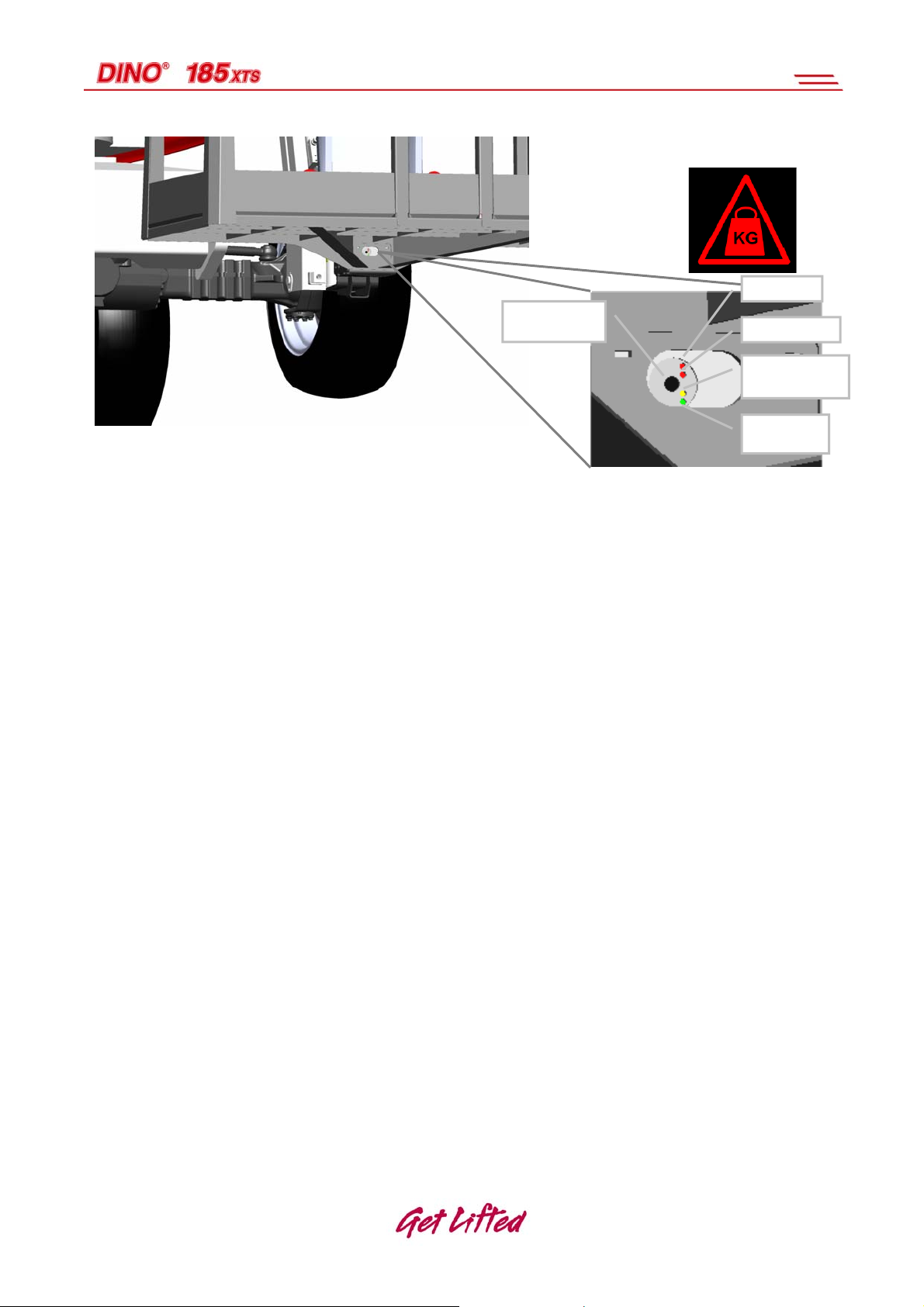
ala
erro
r
User interface
Connecto
MRV: LED signal lights under the work platform
Fault LED (Red) : System failure
Alarm LED (Red) : Load alarm
o overload situation
o the platform has clashed with an obstacle
Reset LED (Orange) : Reset/ dead weight OK
o is illuminated, if the weight of the unloaded platform is OK (unloaded platform
+/-15 kg)
Power on LED (Green) : Power on (illuminated)/in operation (flashes)
o When the power is turned on – the green LED is illuminated.
o Once the sensor is activated, the Green LED starts flashing.
The operation of the platform load control device is checked via the LED
signal lights. When the work platform is unloaded, and is not in contact with
any external structure, the Orange signal light must be illuminated, and the
Green signal light must flash.
r LED
rm LED
reset/calibratio
n LED
power on
22
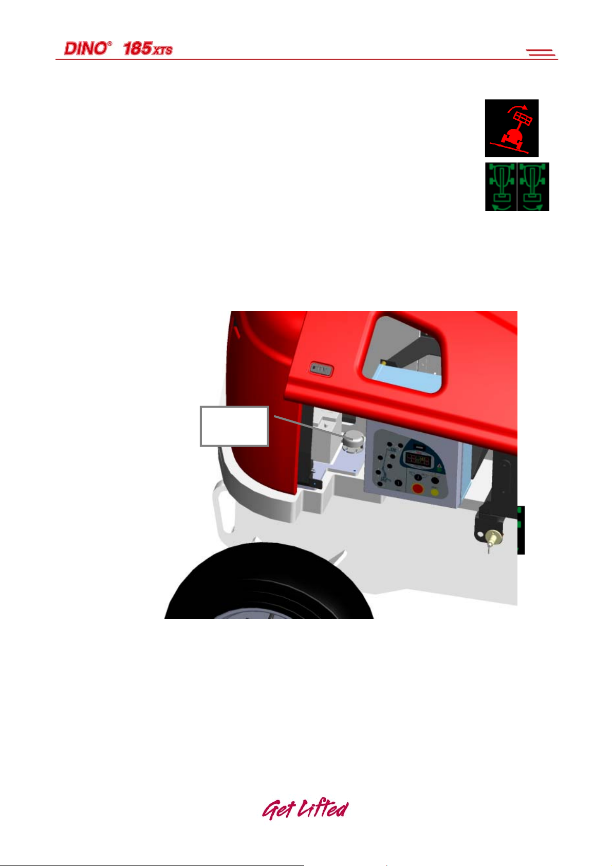
9.5 inclination sensors RK30a and RK30b
The inclination sensor prevents transport driving, if the lift is inclined more
than 5°, and either the boom or the articulated arms have been lifted or the
boom extensions have been extended. The signal light H17 and the buzzer
indicate that the inclination of the lift is greater than 5°. If the inclination
exceeds 5 degrees, the measuring sensor for inclination allows the unit to be
turned only in the safe direction. The inclination is indicated by the signal
lights H23 and H24 in the UCB centre.
The correct operation of the inclination control is tested by driving the lift uphill to an
angle of 5°. (to be established by measuring) If the boom system is moved from its
transport position, the transfer of the lift will be prevented and the signal lights H23 or
H24 will indicate the allowed turning direction.
RK30a and
RK30b
HUOM
Before using the lift, ALWAYS make sure that the safety
devices are operational!
23
10. OPERATING CONTROLS
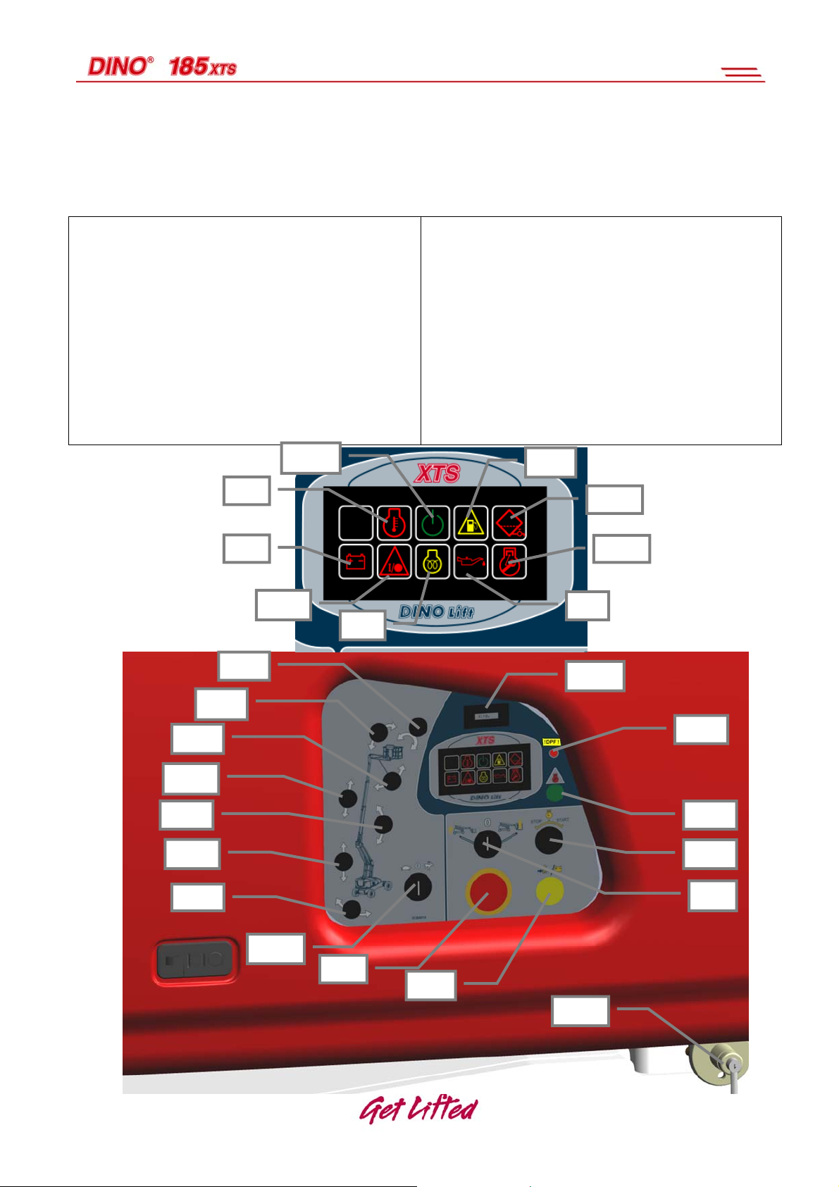
10.1 LCB – CONTROLS IN THE CHASSIS PANEL – XTS
H5 Diesel – Signal light for battery recharging
H6 Diesel – Signal light for oil pressure
H7 Diesel – Signal light for overheating
H9 Diesel – Signal light for glowing
H11 Electrical system, fault signal light
H14 Low fuel, signal light
H20 Electric system active, signal light
H29 Control system failure, Diesel engine
H32 Water trap in fuel system, signal light
HM1 Hourmeter
Q1 Power switch
S1 Emergency stop button
DPF Signal light: The Diesel particle filter needs to
be replaced
H20
S6 Start/stop, engine
S14 Operating switch for emergency descent
system
S16 Turning the boom
S17 Lifting and lowering the boom
S18 Boom extensions in - out
S19 Lifting and lowering the articulated arms
S20 Levelling the platform forward/backward
S21 Jib - arms up - down
S22 Swing of platform to the right - left
S23 Selection of boom speed
S53 Error code button, control system of Diesel
engine
BMS Mains switch
H14
H7
H32
H5
H29
H11
H9
H6
S21
S18
S17
S19
S16
S20
S22
HM1
DPF
S53
S6
Q1
S23
S1
S14
BMS
24
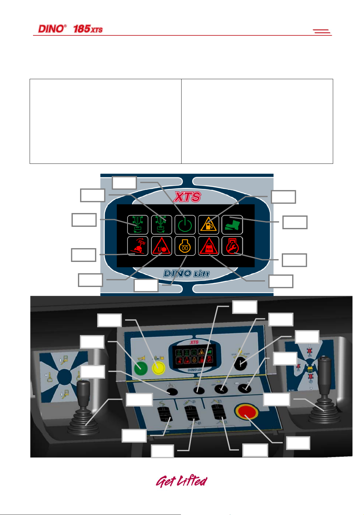
10.2 UCB – OPERATING CONTROLS ON THE PLATFORM – XTS
H10 Glowing of Diesel engine, signal light
H12 Electric system failure
H15 Low fuel
H16 Pedal depressed
H17 Chassis inclined more than 5°
H19 Overload on platform
H21 Electric system active, signal light
H23 Allowed direction of rotation clockwise
H24 Allowed direction of rotation counter-
clockwise
H30 Control system failure, Diesel engine
JSL Control lever for boom
JSR Operating lever for transfer drive
JS2 Lifting and lowering the articulated arms
JS3 Boom extensions in and out
JS4 Lifting and lowering the jib arms
S4 Emergency stop button
S5 Start/stop, engine
S10 Sound signal
S11 Emergency descent
S12 Inclination of work platform
S22 Transfer speed range slow / fast
S32 Platform rotation
S58 Differential lock
H21
H24
H23
H17
H15
H16
H30
H12
S10
S32
S11
JSL
JS2
H10
JS3
H19
S12
S58
S5
S22
JSR
S4
JS4
25
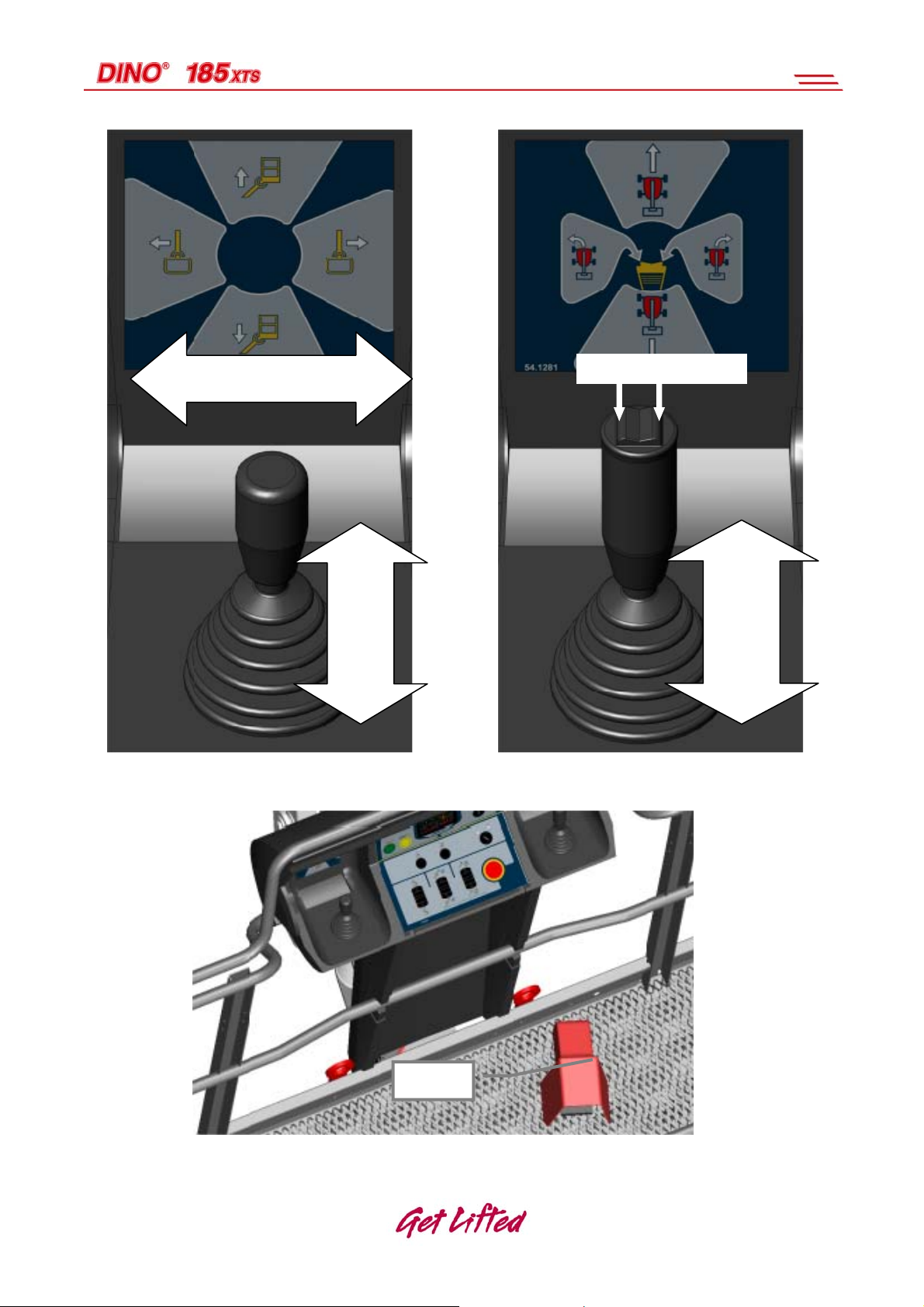
Turning the boom clockwise –
counter-clockwise
Turning the wheels
Boom
Lifting /
lowering
Forward /
Backward
JSL, control lever for boom JSR, control lever for driving
DMS1, Foot pedal on the platform (dead-man-switch)
DMS1
Drive
26

11. MEASURES TO BE TAKEN IN CASE OF EMERGENCY/AT RISK OF
LOSING THE STABILITY
Reduced stability can be caused by a fault in the lift, the wind or other lateral force,
insufficient stability of the standing base or too uneven terrain. In most cases one sign of
reduced stability is the inclination of the lift.
WHEN AT RISK OF LOSING THE STABILITY
1. If there is time, try to find out the reason for the reduced stability and the direction of its
effect. Warn other people on the worksite using the alarm signal.
2. If possible, reduce the load from the platform in a safe manner.
3. Reduce the outreach to the side by retracting the telescope. Avoid abrupt movements.
4. Turn the boom away from the danger zone, i.e. to a position where the stability of the lift
is normal.
5. Lower the boom.
If the stability has been lost as a result of a fault in the lift, repair such a fault immediately.
Do not use the lift until the fault has been repaired and the condition of the lift has
been verified.
IN CASE OF OVERLOADING
The engine shuts down and the movements stop, the red signal light H17 is
flashing and the buzzer sounds intermittently.
1. If there is time, try to find out the reason for the reduced stability and the direction of its
effect. Warn other people on the worksite using the alarm signal.
2. Reduce the platform load.
3. The red signal light is turned off and the sound signal stops as soon as the overload
situation ends. After this the machine can be operated normally.
IN CASE THE POWER SUPPLY IS INTERRUPTED (diesel)
1. Lower the boom using the emergency descent system (see point “Emergency descent
system”).
2. Only the movements of the boom are possible using the emergency descent system.
(NOTE that the movements are much slower with the emergency descent system).
27

3. Establish the reason why the energy supply was interrupted.
IN CASE OF MALFUNCTION, WHEN EVEN THE EMERGENCY DESCENT SYSTEM IS
NOT OPERATIONAL
1. If the emergency descent system does not operate, try to warn other personnel present
on the site or call for help so that the normal operation of the emergency descent
system can be resumed, for example, by changing the battery or by making the lift
operative by some other means so that the person on the platform can be lowered
safely down.
Always check the condition of the emergency descent system battery before putting the lift
into operation.
12. STARTING UP
12.1 Familiarise yourself with the machine and these instructions
Read these instructions carefully and check out the warning and
instruction decals affixed to the machine before starting the
operation.
12.2 Starting the engine
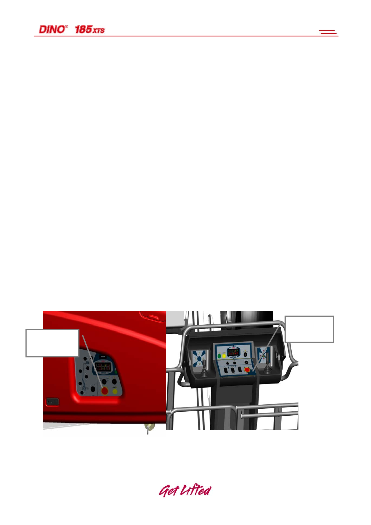
12.2.1 From the chassis control panel LCB
1. Familiarise yourself with the switches and lights mentioned in this chapter in point
“LCB – operating controls in the chassis panel – XTS”
2. Perform the daily inspection (see point “Daily inspection” (also called “Start-up
inspection”)).
3. (See point “Worksite inspection”.)
4. Make sure that the mains switch (BMS) is turned on, and that the emergency stop
buttons (S1 and S4) have been pulled up.
5. Turn the power switch Q1 to the left to position: LCB - Chassis control panel.
6. Wake the electric system by keeping the switch S23 (rabbit/tortoise) turned for about
2-3 seconds.
The signal light H20 “Electric system
active” will then be illuminated.
28

If the engine is cold, the glowing will occur
automatically. The signal light for glowing
H9 will remain illuminated until glowing of
the engine is completed. As soon as the
light is switched off, the engine is ready to start.
7. Turn the start switch S6 to the right to the position Start and keep it in this position
until the engine starts. To switch off the engine, turn the switch S6 to the left.
Make sure that no signal light other than
the light H20 (Electric system active)
remains lit.
Note! If the engine is not running, and the movements are not actuated, the electric system
goes into sleep mode in about 30 minutes. Then it must be reactivated by using the switch
S23 anew.
12.2.2 From the platform control panel UCB
1. Familiarise yourself with the switches and lights mentioned in this chapter in: UCB –
operating controls in the platform panel – XTS
2. Perform the daily inspection (see point “Daily inspection (start-up inspection)).”
3. Perform the worksite inspection (see point “Worksite inspection”).
4. Make sure that the mains switch (BMS) is turned on, and that the emergency stop
buttons (S1 and S4) have been pulled up.
5. Turn the power switch Q1 in the LCB panel to the right to position: Platform control
panel. Take the keys with you, when you go to the UCB centre on the platform.
6. Wake the electric system by keeping the pedal depressed for about 2-3 seconds.
Then the Electric system active signal light H21 in the
UCB panel will be illuminated.
If the engine is cold, the glowing will take place
automatically. The signal light for glowing H10 will
remain illuminated until glowing of the engine is
completed. As soon as the light is switched off, the
engine is ready to start.
7. Turn the start switch S5 to the right, to position Start, and keep it in this position until
the engine starts. To switch off the engine, turn the switch S5 to the left.
29

Make sure that, while the engine is running, only the signal light H21
“Electric system active”, and the lights H23 and H24, which indicate the
allowed direction of rotation of the turning
device, remain illuminated.
Note! If the engine is not running, and the movements are not actuated, the electric system
goes into sleep mode in about 30 minutes. Then it must be reactivated by pressing the
pedal anew.
Allow the engine to warm up at low revolutions for a few minutes before loading it.
Allow the combustion engine to run sufficiently also between the operations,
because the battery will only be recharged when the combustion engine is running.
However, if you are working for a longer period of time in the same position, it pays
to turn off the engine for a while occassionally.
To avoid damaging the recharger electronics of the diesel engine, do not disconnect
the mains current while the diesel engine is running!
If any of the warning lights remains illuminated, turn off the engine and find out the
reason. Repair the faults before re-start.
If the signal light – H29 or H30 – for the control system of the Diesel
engine remains illuminated or flashes, contact the service personnel.
The signal lights H30 or H29 indicate the following:
o function test: turn the power on – the light shall remain lit for about 2 seconds,
and after that, goes out.
o The going out of the light after the function test indicates that the system is
operating correctly.
o If the light remains illuminated, the system is faulty. The operation can be
continued under certain conditions. The engine must then be checked by a
mechanic authorised by DEUTZ.
o A flashing signal light is an indication of a serious fault in the system. In this
case the engine must be switched off immediately.
NOTE
By depressing the switch S53, the signal light H30 can be made to flash the
error code.
Contact an authorised service representative for interpretation of the error
code. We recommend turning to the service staff of the dealer.
30
 Loading...