

Dino lift DINO 180 T, Dino 180XT Operation Instructions Manual
DINO ® 180T
OPERATION INSTRUCTIONS
®
Raikkolantie 145
FI-32210 LOIMAA
T. +358 2 762 5900
F. +358 2 762 7160
dino@dinolift.com
www.dinolift.com

DINO 180T-1
2

DINO 180T-1
3
OPERATION INSTRUCTIONS
Valid from serial number 4505

DINO 180T-1
4
CONTENTS
REACH DIAGRAM..................................................................................................................................6
TECHNICAL SPECIFICATION............................................................................................................7
GENERAL SAFETY DIRECTIVES.......................................................................................................8
REGULAR INSPECTION .....................................................................................................................10
INSPECTION ON THE WORKSITE ..................................................................................................11
SAFETY DEVICES ................................................................................................................................12
OPERATING CONTROLS ...................................................................................................................14
LOWER PANEL CONTROLS..............................................................................................................14
CONTROLS MOUNTED ON THE CHASSIS .....................................................................................15
PLATFORM PANEL CONTROLS.......................................................................................................16
MEASURES TO BE TAKEN IF STABILITY IS THREATENED...................................................17
STARTING UP THE LIFT....................................................................................................................18
OPERATING THE UNIT FROM THE CHASSIS CONTROL PANEL...............................................21
OPERATING THE UNIT FROM THE WORK PLATFORM ..............................................................22
EMERGENCY DESCENT SYSTEM ...................................................................................................26
DRIVING DEVICE.................................................................................................................................27
SPECIAL INSTRUCTIONS FOR WINTER USE ..............................................................................30
ENDING THE DAYS WORK................................................................................................................31
PREPARING THE LIFT FOR TRANSPORT ....................................................................................32
CONNECTING TO THE TOWING VEHICLE .................................................................................33
SERVICE AND MAINTENANCE........................................................................................................34
GENERAL.............................................................................................................................................34
INSPECTIONS AND SERVICE ...........................................................................................................35
LUBRICATION PLAN .........................................................................................................................36
HOLD- AND LOAD REGULATING VALVES...................................................................................39
WHEEL BRAKES AND BEARINGS...................................................................................................40
PLATFORM STABILIZATION SYSTEM...........................................................................................43
REGULAR SERVICING.......................................................................................................................44
TESTING THE LOAD LIMITS ...........................................................................................................50
SETTING THE OVERLOAD DEVICES RK4 AND RK5 ....................................................................52

DINO 180T-1
5
INSPECTING THE LIFT ......................................................................................................................56
FIRST INSPECTION.............................................................................................................................56
DAILY INSPECTIONS.........................................................................................................................57
INSPECTIONS ONCE A MONTH .......................................................................................................58
REGULAR INSPECTION (ANNUAL) ................................................................................................59
EXTRAORDINARY INSPECTION .....................................................................................................62
TEST LOADING IN CONJUNCTION WITH THE REGULAR SERVICE ........................................63
FAULT FINDING ...................................................................................................................................64
HYDRAULIC SYSTEM, GENERAL INFORMATION ....................................................................70
ELECTRIC COMPONENTS' FUNCTION.........................................................................................72
LOWER CONTROL PANEL (PK), RELAYS ......................................................................................72
LOWER CONTROL PANEL (PK), SWITCHES..................................................................................73
UPPER CONTROL PANEL (OK), RELAYS .......................................................................................74
UPPER CONTROL PANEL (OK), SWITCHES...................................................................................74
LIMIT SWITCHES................................................................................................................................75
OTHER
MARKINGS ............................................................................................................................76
PROPO
-CONTROL CARD..................................................................................................................77
ELECTRONIC COMPONENTS ..........................................................................................................78
ELECTRIC SCHEMA............................................................................................................................79
HYDRAULIC COMPONENTS.............................................................................................................90
HYDRAULIC SCHEME........................................................................................................................91
DINO 180T-1
6
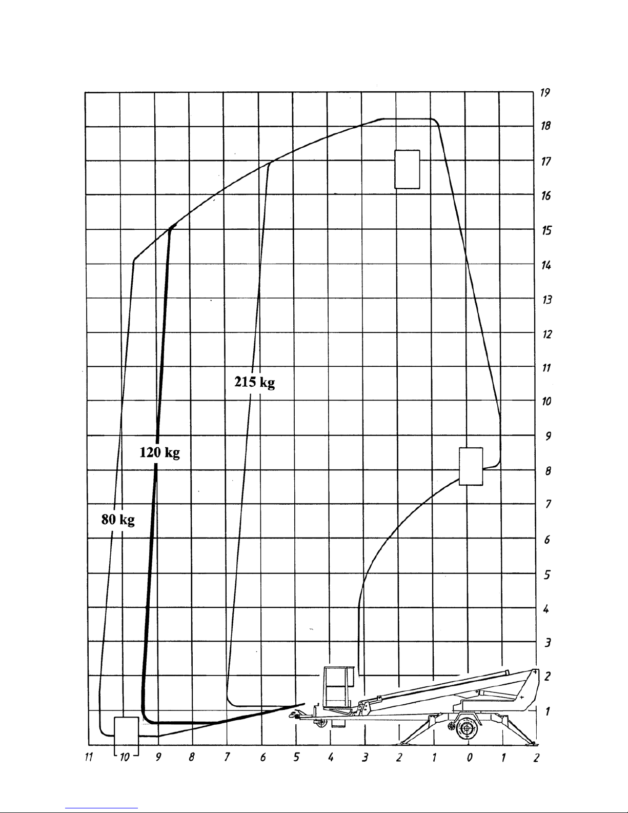
REACH DIAGRAM

DINO 180T-1
7
TECHNICAL SPECIFICATION
Max. working height 18,0 m (59’1”)
Max. platform height 16,0 m (52’6”)
Max. outreach 10,7 m (35’1”)
Boom rotation continuous
Platform rotation 90°
Reach when turned refer to reach diagram
Support width 3,88 m (12’9”)
Transport width 1,78 m (5’10”)
Transport length 7,35 m (24’1”)
Transport height 2,00 m (6’7”)
Weight 1750 kg (3850 lbs)
Lifting capacity 215 kg (474 lbs)
Max. number of persons + load 2 persons + 55 kg (120 lbs)
Max. allowed sideways load (caused by persons) 400 N (88 lbs)
Max. sideways inclination (chassis) ±0,3°
Max. wind force when working 12,5 m/s (41 ft/s)
Min. ambient temperature when working - 20 °C (- 4 °F)
Max. support force on the outriggers 16800 N (3800 lbs)
Platform size 0,7 x 1,3 m (2'4" x 4'3")
Gradeability 25%
Power supply:
- internal combustion engine 4,8 kW (6,5 hp)/ 3600 r/min
- mains current 230V/ 50Hz/ 16A
Socket outlets on the platform 230V/ 50Hz / 10A
Socket outlets on the platform (GB) 110V/ 50Hz / 10A
Socket outlets on the platform (US) 110V/ 60Hz / 10A

DINO 180T-1
8
GENERAL SAFETY DIRECTIVES
Make yourself familiar with the operators manual before using the lift!
The operator's manual should be stored in the space reserved for it.
Make sure that all persons working with the lift are familiar with the operator's manual.Inform new
users about the operation of the lift and the manual.
All the manufacturers directions and recommendations should be followed strictly.
Make sure you know well all directions that deal with the operating safety of the lift.
Always use the brake beams when leaving the lift from the tow vehicle.
Only personnel who have received training in the use of the lift and are at least 18 years of age is
allowed to use the lift.
AT LEAST YEARS + TRAINING
No more than two persons and max. additional load of 55 kg (120 lbs) or max. total load of 215 kg (474
lbs) are allowed on the platform.
When the chassis is supported by the outriggers, the carrying capacity of the ground and any possible
inclination of the support area must always be considered.
On soft ground the outriggers should be additionally supported by adequately sized support plates.
When choosing additional support plates or other aids, always make sure that the outrigger feet cannot
slip when resting on them.
The lift may be moved only when it is in transport position. When moving the lift no persons or
workloads are allowed on the platform.
Weather factors, ie. wind, visibility, outdoor temperature, rain and so on, must always be taken into
consideration when using the lift, so that the necessary precautions to eliminate dangers caused by these
are always taken.
It is not allowed to use the lift under following conditions:
- temperatures below -20 °C (-4 °F)
- wind speed over 12,5 m/s (41’/s)
18

DINO 180T-1
9
No ladders, steps or other similar equipment may be used on the platform.
Objects may under no circumstances be thrown out from the platform.
The lift must not be used to move persons or objects between floors or different work levels.
The safety devices must not in any circumstances be put out of function.
Before lowering the platform, always make sure that there are no obstacles on the chassis. The platform
must not be lowered onto the ground, or brought in contact with other objects, as this will constitute a
risk for damages.
If the lift is used in areas where there is other traffic, the working area must be equipped with warning
lights and, if necessary, fenced in.
All regulations concerning road traffic and working safety must always be respected.
Always be especially careful when working in the vicinity of open-wire power lines.
Do not forget the stipulated minimum safety distances (refer to table).
The lift must be regularly cleaned, so that dirt does not influence the operational safety, or make regular
inspections inconvenient and unreliable.
The lift must be inspected and serviced regularly. Service and repairs may be performed only by trained
personnel, who are familiar with the operating-, service- and repair manuals.
The lift may never be used if it is not in faultless condition.
No technical, constructional or other changes may be made to the unit without written permission
from the manufacturer.
Voltage Min. under distance
m (ft)
Min. sideways distance
m (ft)
100 – 400V hanging cable 0,5 (2) 0,5 (2)
100 – 400V open-wire cable 2 (7) 2 (7)
6 – 45 kV 2 (7) 3 (10)
110 kV 3 (10) 5 (17)
220 kV 4 (13) 5 (17)
400 kV 5 (17) 5 (17)

DINO 180T-1
10
REGULAR INSPECTION
A thorough inspection must be made at least once every twelve (12) months.
The inspection should be made by a person who is technically trained and is familiar with the function,
use and construction of the lift.
Inspections should be recorded in a protocol that should always follow the unit and be stored in the
space reserved for it.
The inspections must be made regularly throughout the operative life of the lift.
The inspections must be made within twelve (12) months from the first or the previous inspection.
If the lift is used in especially severe conditions, inspection intervals should be shorter than mentioned
above.
The general operating conditions of the lift, and safety- and control devices should be established
through regular inspections. Special attention should be paid to factors that influence the operating
safety.
It should also be established if the findings of the previous inspection, or the experiences gained when
using the unit could give cause to further improve the operational safety of the unit.
ATTENTION! Primarily the national legislation must be followed!
Regular inspections and service measures are described more thoroughly in the chapter "Service- and
maintenance".

DINO 180T-1
11
INSPECTION ON THE WORKSITE
1. General
- Is the lift suited for the job at hand?
- Is the performance of the lift sufficient for the job (reach, loadability etc.)?
- Is the lift located safely on a site so that no negative influence on work safety is possible?
- Is there enough illumination for safe working?
2. Documents
- Are the operating and service instructions for this particular lift present? (Manufacturers manual)
- Have the inspections and service measures mentioned in the instructions been made and defects that
could influence safety been repaired? (Inspection protocols)
3. Structures and construction (Optical inspection and functional test)
- General condition of the lift
- Functioning and protection of controls
- Emergency stop, signal horn and limit switches
- Electrical devices and cables
- Oil leaks
- Load markings and signs
4. Operator
- Is the lift operator old enough?
- Has the operator recieved the necessary training?
5. Special circumstances on the work site
- Are there factors connected with the work site or work task that demand special attention or
additional instructions / directives?
DINO 180T-1
12
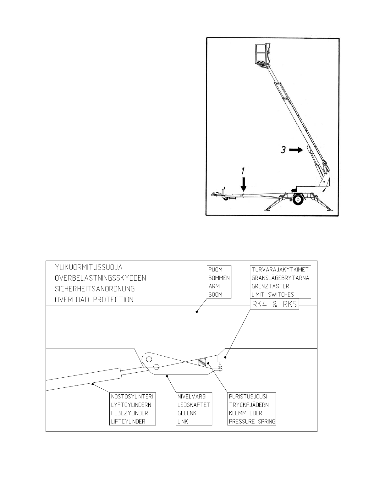
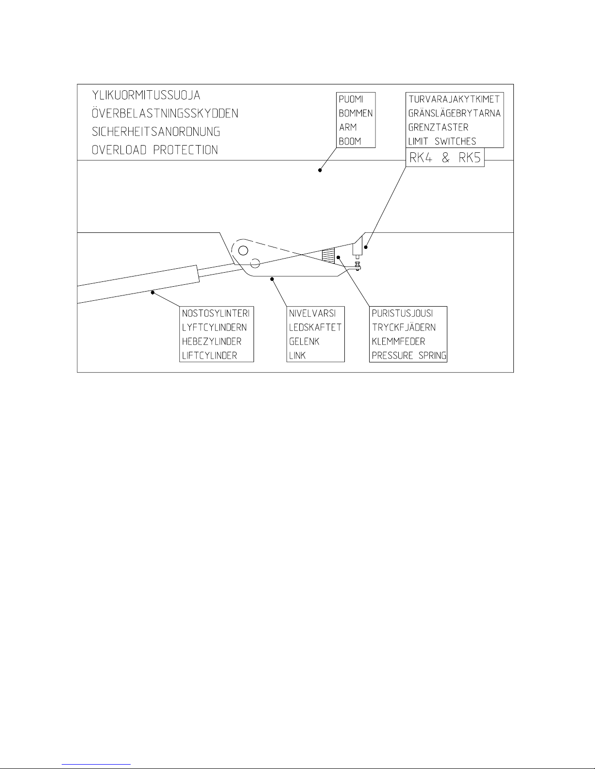
SAFETY DEVICES
1. Support outriggers
A safety limit switch RK3 prevents use of the
outriggers and the drive mechanism when the boom
is lifted off the transport support.
The limit switch is mounted on the tow bar boom
support point.
3. Overload protection switches
The safety limit switches prevent overloading the lift.
When arriving at a certain preset reach, the overload
switch RK4 stops extending or lowering the
telescopic boom. The overload switch RK5 has a
back-up function, for the case that the overload
switch RK4 is not working.
When the lift is working within the permissible reach
zone the green light in the control panel is lit. If the
movement is stopped by the limit switches, a red light
is lit. When the red light is lit the boom can be moved
in the direction where it stays within the allowed
reach zone.
The limit switch RK5 backs up the RK4 and switches the platform alarm horn on.
RK4 & RK5
RK3
DINO 180T-1
13
2. Lifting the boom
Lifting of the boom is prevented
by safety limit switches when
the wheels are not lifted off the
ground, ie. when the lift is not
supported by the supporting
outriggers.
The limit switches RK11,
RK12, RK13 and RK14 are in
the outriggers.
4. The EMERGENCY STOP pushbutton immediately stops the movement and shuts off the
power unit. The power unit can not be restarted before the EMERGENCY STOP pushbutton is
lifted (buttons 3 and 22).
Do not prevent the function of safety devices - the cover of the chassis control panel must not be
locked with key when using the lift.
RK11, RK12, RK13, RK14
DINO 180T-1
14
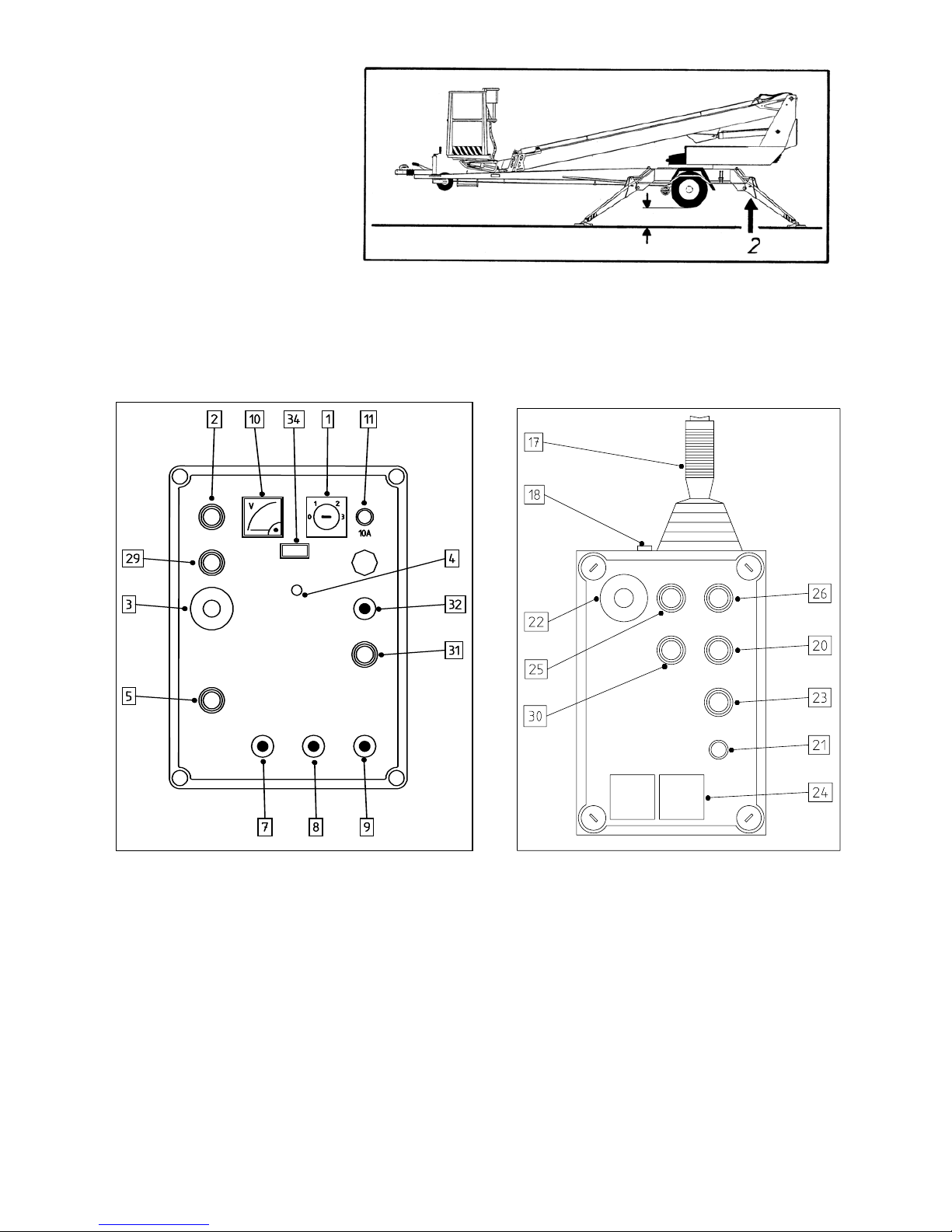
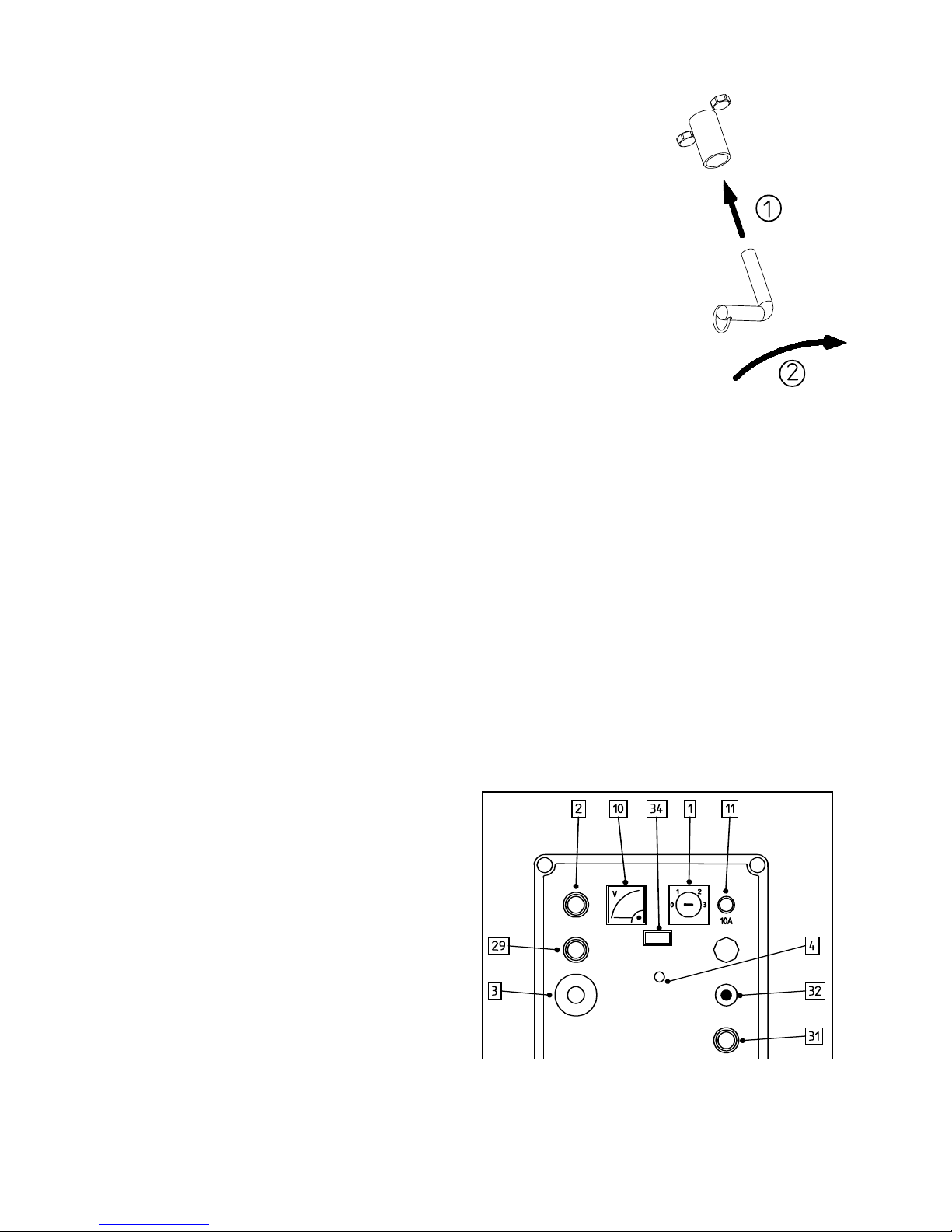
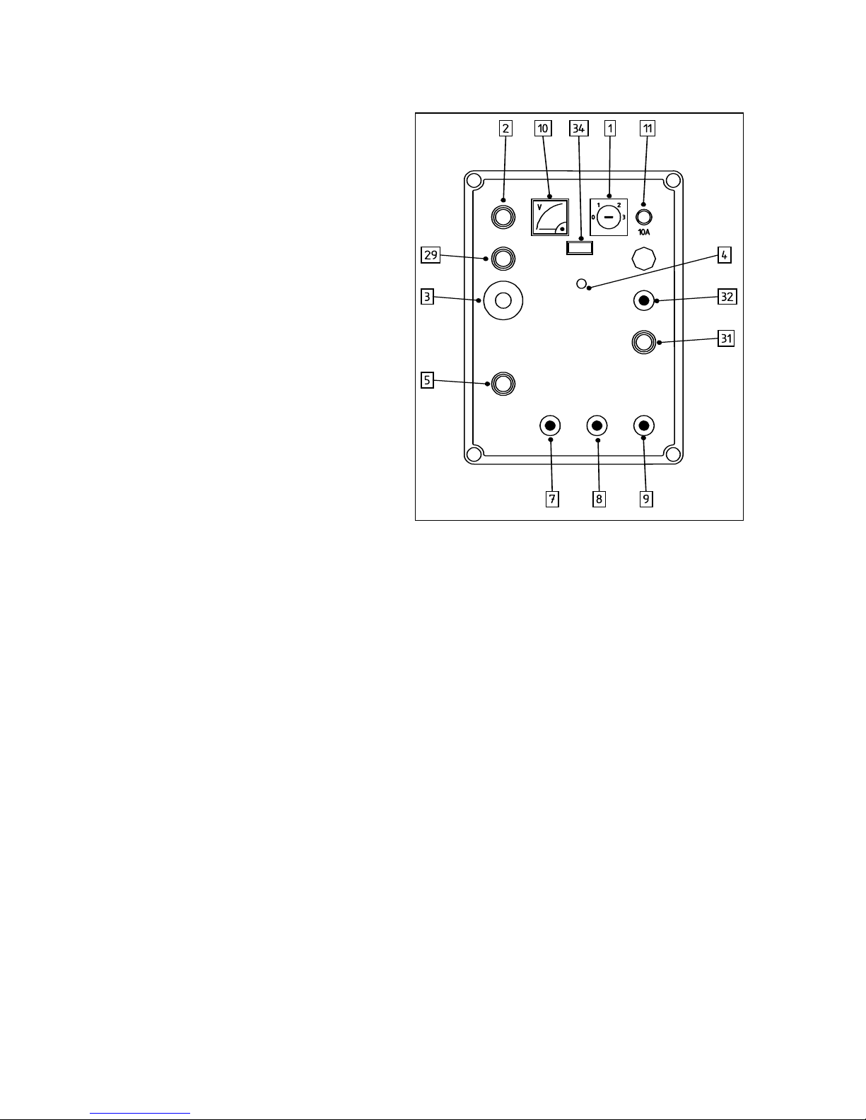
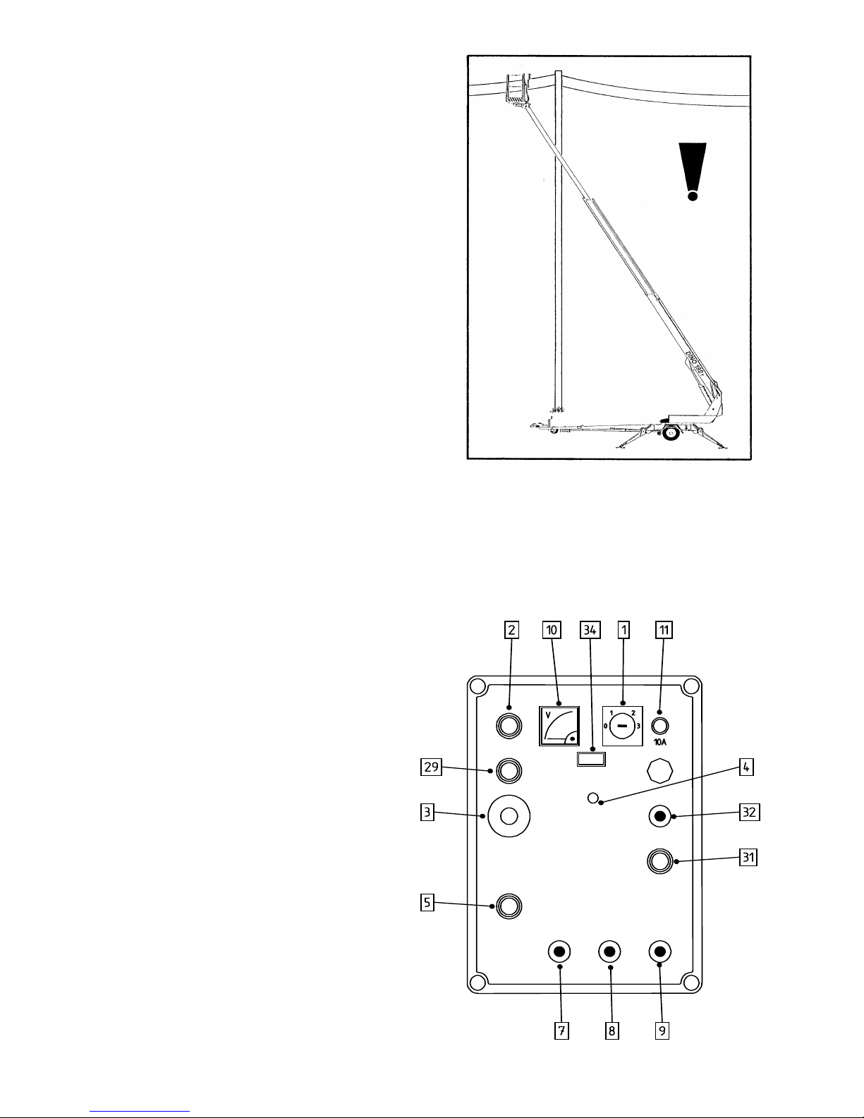
OPERATING CONTROLS
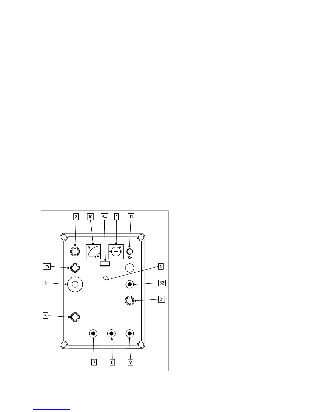
LOWER PANEL CONTROLS
1. Operating switch
0 = Off
1 = Operation of support outriggers and moving the lift by hydraulic power (driving
device)
2 = Controlling the boom from the platform
3 = Controlling the boom from the chassis
2. Start -pushbutton
3. Emergency stop
- stop by pushing
- release by lifting
4. Signal light, outrigger limit switches
5. Start -pushbutton, emergency descent
7. Turning lever
8. Boom movement lever
9. Telescopic movement lever
10. Voltage meter
11. Fuse
29. Stop -pushbutton
31. Telescope in -pushbutton
32. Platform inclination, operating lever
34. Hour meter
DINO 180T-1
15
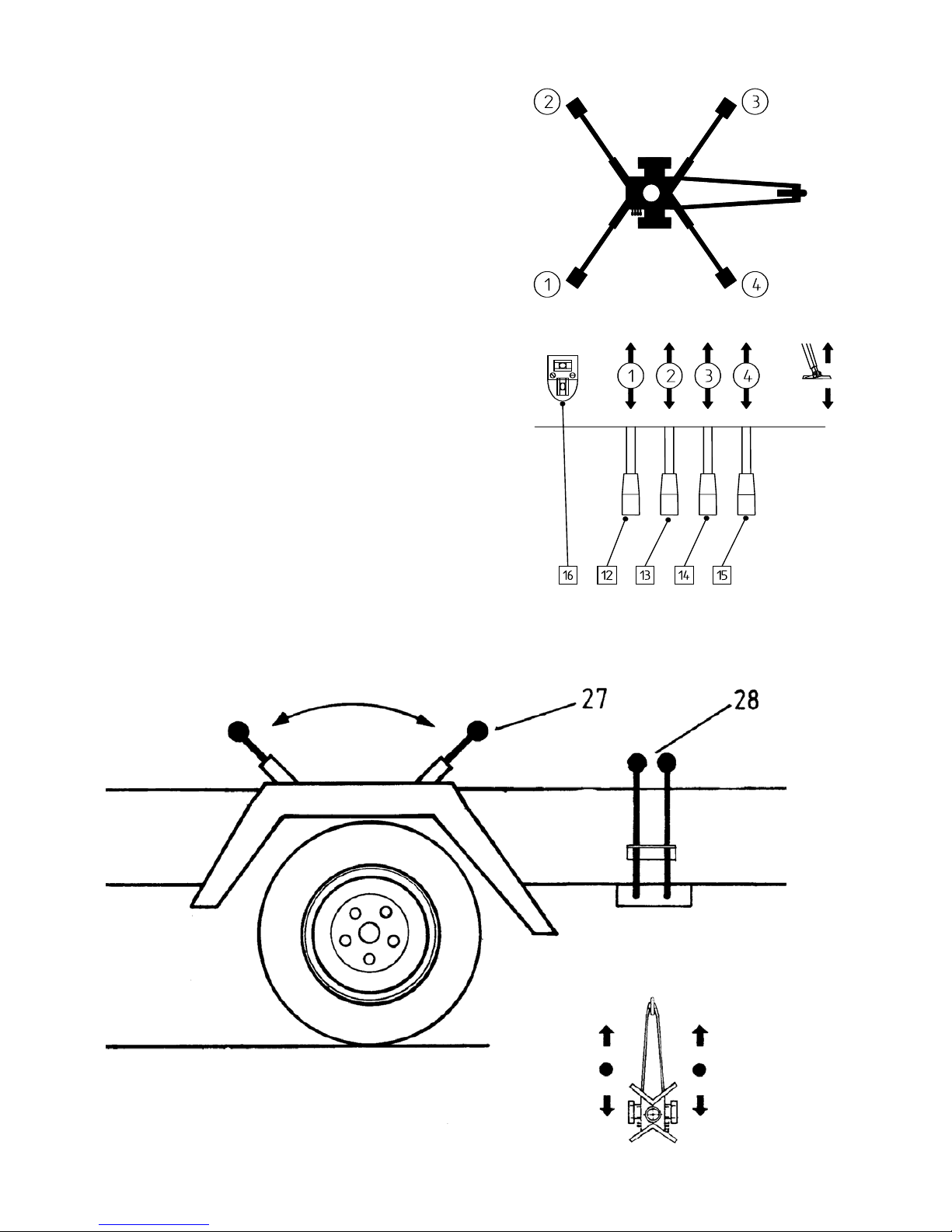
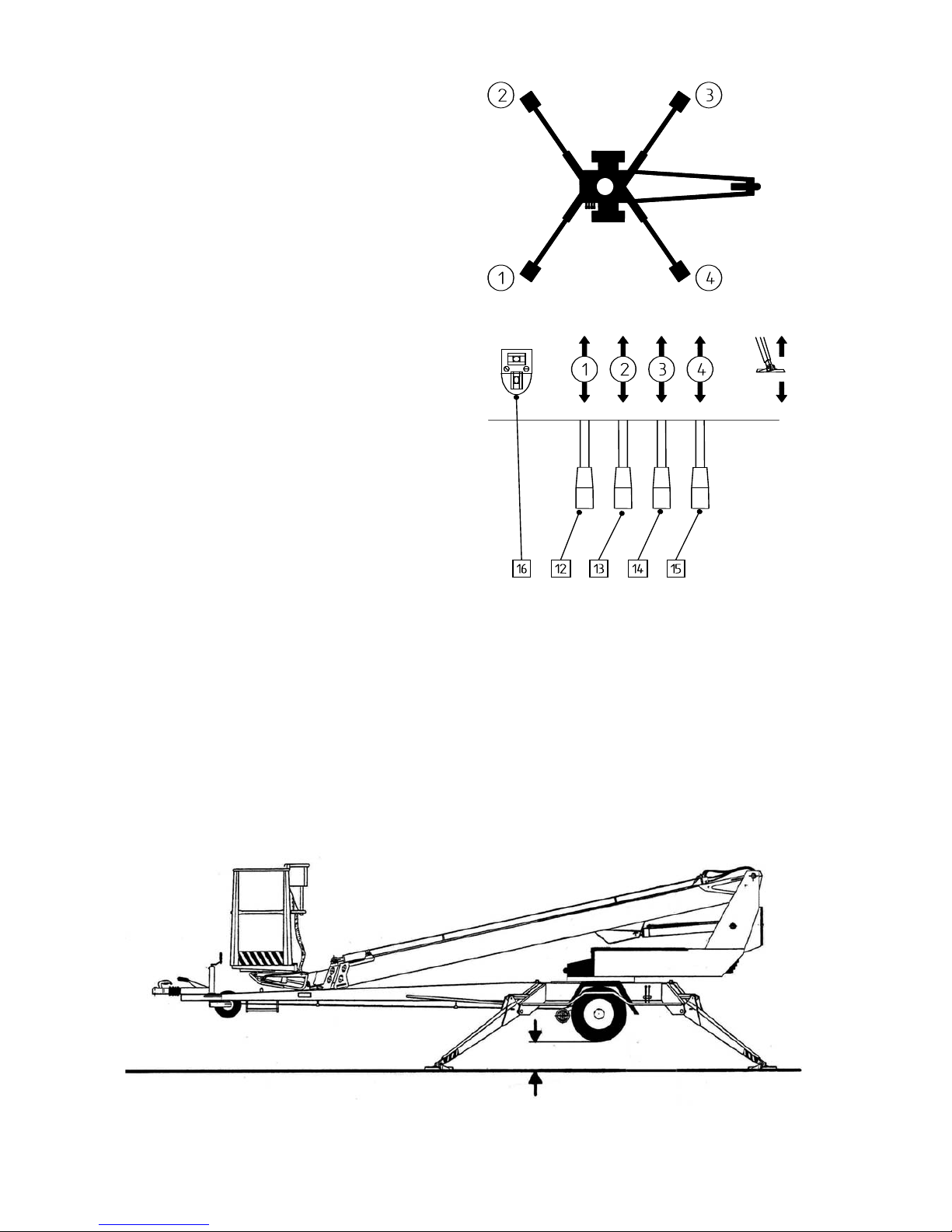
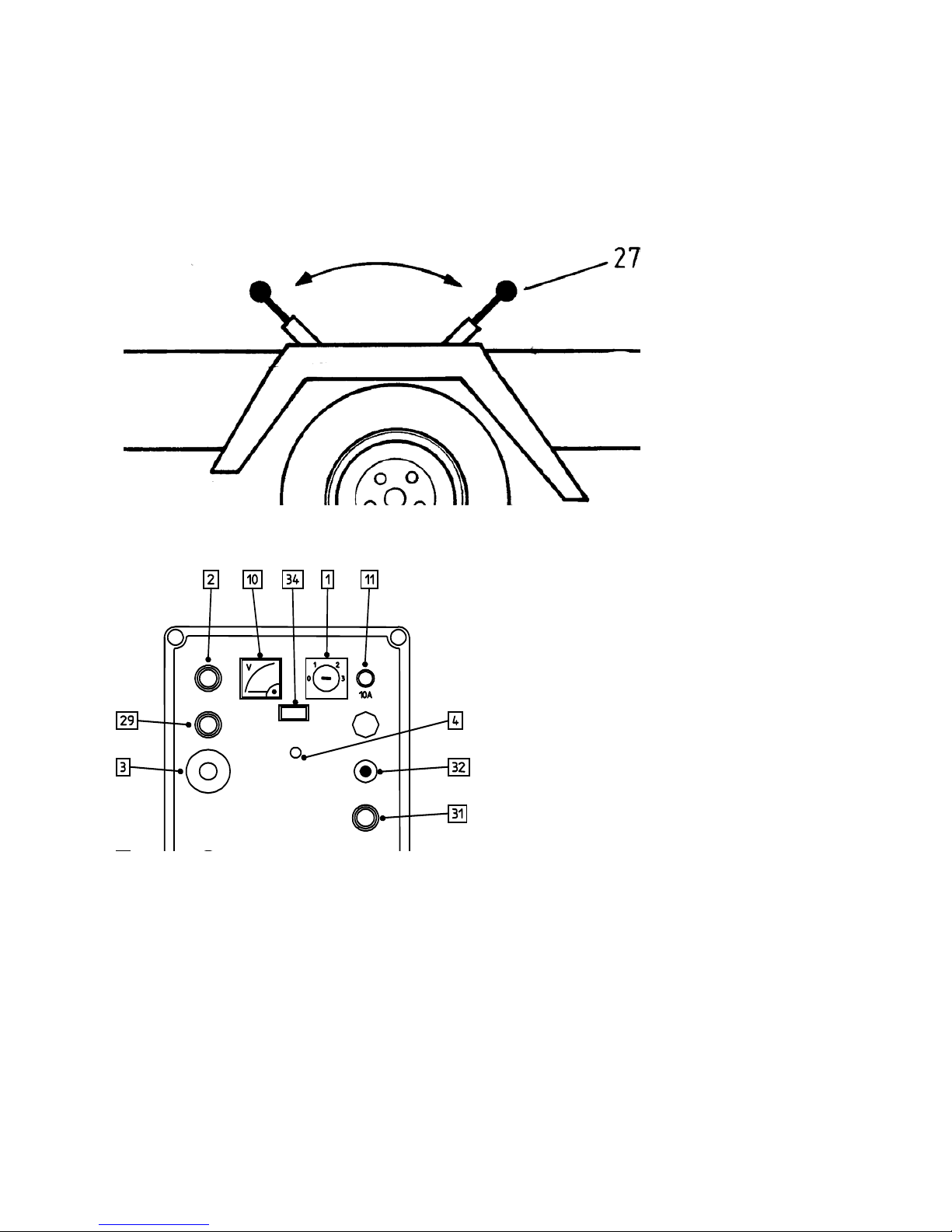
CONTROLS MOUNTED ON THE CHASSIS
12. Right rear support outrigger
13. Left rear support outrigger
14. Left front support outrigger
15. Right front support outrigger
16. Levelling gauge (chassis)
27. Hydraulic movement, on - off
28. Hydraulic movement, operating levers
MOVEMENT OFF/ MOVEMENT ON
FORWARD
LEFT
WHEEL
RIGHT
WHEEL
REARWARD
DINO 180T-1
16
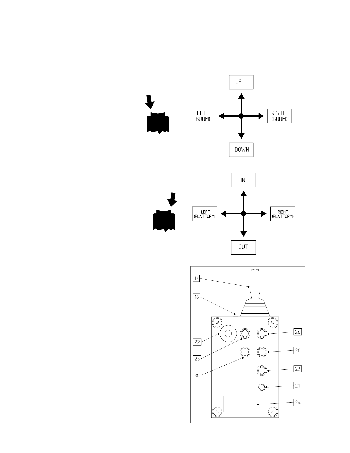
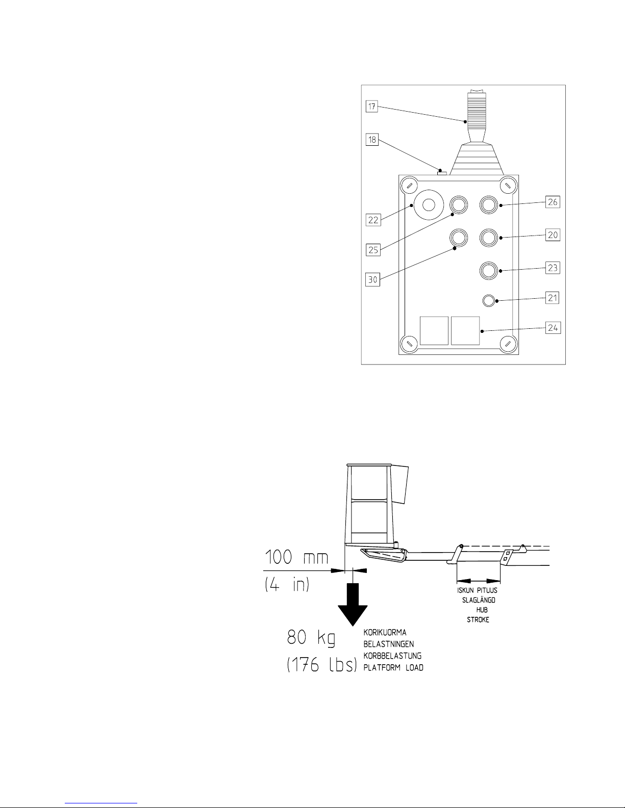
PLATFORM PANEL CONTROLS
Close the chassis control panel cover before using the platform controls (the cover must not be locked
when using the lift).
17. Operating lever
18. Warning lights
green = inside the reach limits
red = at the reach limit
20. Start -pushbutton, emergency descent
21. Fuse
22. Emergency stop -stop by pushing
-release by lifting
23. Signal horn
24. Socket 2 pcs. (230VAC)
25. Motor OFF
26. Motor START
30. Telescope in -pushbutton

DINO 180T-1
17
MEASURES TO BE TAKEN IF STABILITY IS THREATENED
The following factors can lead to loss of standing stability:
- a technical fault in the lift
- wind or other factors that can create sideways forces
- a decrease in ground firmness
- negligence when positioning and raising the lift
A decrease in standing stability is mostly perceived as an increase in the inclination of the lift and boom.
1. If there is enough time, you should try to find out the cause of the instability and ascertain in which
direction the destabilizing forces are working.
Warn persons in the vicinity by using the alarm horn.
2. Retract the telescope, so that the sideways reach is reduced.
Carefully avoid all sudden movements.
3. Turn the boom away from the dangerous zone/direction, that is, in the direction where it acts towards
increased stability.
4. Lower the boom.
If the destabilization is caused by a technical fault in the lift, the fault must be rectified immediately.
The lift must not be used before the fault has been rectified and the lift properly inspected.
DINO 180T-1
18
STARTING UP THE LIFT
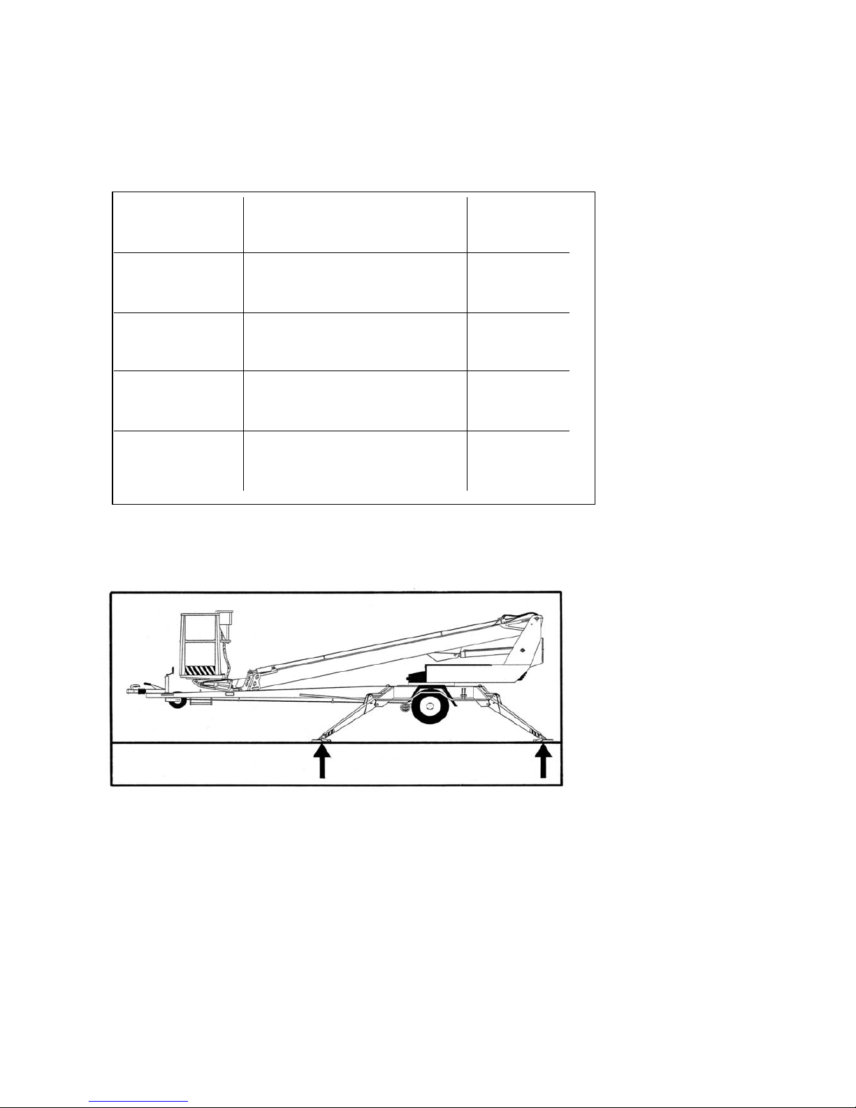
1. Ground stability
- Make sure that the ground is even and level, and hard enough to support
the lift in a steady, level position (see table below).
- On soft ground, support plates that are large and stable enough should be placed
under the support outriggers (see figure below).
- Always make sure that the support feet cannot slip because of ice, rain or ground inclination.
- It is prohibited to use the lift, if it is not properly supported and completely level.
2. The lift should be driven or pushed onto the area where it is to be used.
- Apply the parking brake
- Disconnect the towing vehicle
Ground material Density Max. ground
pressure
P kg/cm²
Gravel High density 6
Medium density 4
Loose 2
Sand High density 5
Medium density 3
Loose 1,5
Fine sand High density 4
Medium density 2
Loose 1
Sand/ mud High density (very hard to work) 1,00
Medium density (hard to work) 0,50
Loose (easily worked) 0,25
DINO 180T-1
19
3. Power connection
A. AC power
- Connect the mains cable (230VAC or 110VAC)
- Turn on the mains switch
- Voltage should be
• 230VAC (-10%/ +6%), frequency 50Hz, and mains fuse 16A
• 110V ± 15V, frequency 50Hz, and mains fuse 16A (GB)
• 110V ± 15V, frequency 60Hz, and mains fuse 16A (US)
when electric motor is loaded with max. load
(using a long cable may cause a voltage drop)
B. Interna combustion engine power (petrol/ gasoline aggregate)
- Do not connect the mains cable (230 VAC or 110 VAC)
- Turn on the mains switch
- Open the fuel cock
- Turn on the choke
Starting the engine when the battery is flat:
Press the push button located in the bed of the aggregate and pull the starter grip at the same time.
Pull the starter grip lightly until you feel resistance, then pull briskly.
Caution! Do not allow the starter grip to snap back against the engine. Return it gently to
prevent damage to the starter.
- Adjust the motor running speed to middle position
Keep the aggregate running between movements too, because the battery will only be charged when the
aggregate is running.
Attention! The fuel cock must be closed when the lift is towed!
4. Open the chassis control panel cover
Check that the battery voltage is adequate to make sure that the emergency descent system is in working
condition.
The charging level of the battery is indicated by two LEDs.
When charging the battery the red LED is on and the green one is off.
- when the battery is charged to 80% , both LEDs are on
- when the battery is fully charged, the green LED is on and the red one blinks
- if both LEDs are on after full charging, the battery is dead.
5. Turn the operating switch (1) into position 1
6. Start the motor with pushbutton 2 (green)
Petrol/ gasoline engine
- switch off the choke
- adjust the motor running speed
DINO 180T-1
20
7. Lower the front support outriggers
(towbar)
8. Lower the rear support outriggers
9. Use the outriggers to adjust the chassis so
that it stands level
Make sure that the wheels are clearly off the ground
- when the wheels are off the ground, the signal light 4A on the chassis control panel is lit.
- make sure that all support outriggers are against the ground
DINO 180T-1
21
OPERATING THE UNIT FROM THE CHASSIS CONTROL PANEL
10. Turn the operating switch (1) into
position 3
- The boom can be operated using the levers
7, 8 and 9
- Test the emergency descent function as
follows:
1. Lift the boom about 1-2 m (47 ft) (lever 8) and extend the
telescope about 1-2 m (4-7 ft).
Push the emergency stop button.
The movement must now stop.
2. Start the emergency descent
power unit (pushbutton 5),
retract the telescope (lever 9)
and lower the boom (lever 8).
3. Lift up the emergency stop push button.
4. Lift up the platform from the tow bar and turn it to the side, so that it can be lowered.
5. Extend the telescope enough to make it possible to enter the platform safely.
Do not damage the tow bar jockey wheel!
Movements are noticeably slower when using the emergency descent function.
When using the chassis control panel the speed of the boom movements cannot be adjusted continually
with the control lever.
Lock the operating switch (1) into position 1 (support outriggers) when you work beneath the boom.
Make sure that there is no person or load in the platform.
DINO 180T-1
22
OPERATING THE UNIT FROM THE WORK PLATFORM
11. Turn the operating switch (1) into position 2 and
take away the key.
The cover of the chassis control panel must not be locked
with key.
- now you can operate the lift from the work platform lever
17.
First push the rocking switch on the control lever end, and
carefully move the lever in the desired direction of
movement.
- test the emergency descent function as follows:
- Lift the boom about 1-2 m (4-7 ft) with
lever 17 and extend the telescope about 1-2
m (4-7 ft). Push the emergency stop -button.
The movement must now come to a halt.
- Start the emergency descent power unit
(pushbutton 20), retract the telescope and
lower the boom (lever 17).
- Lift up the emergency stop -button.
Do not damage the towbar jockey wheel!
The platform movement speed is continually adjusted with the lever 17.
12. Test function of the overload
limit switch RK4.
- Platform load about 80 kg (176 lbs)
- Move the boom to horizontal
position
- Extend the telescope. When the
movement stops the red overload
warning light (18) should light up.
- Compare the actual reach to the
figures in the reach diagrams (page 6)
Front edge of the platform
= reach - 0,5 m (20 in.)

DINO 180T-1
23
12A. Measures to be taken after overload situation.
(Overload limit switch RK5 disconnects the electric circuit from the controls and the platform
alarm horn on.)
- retract the telescope by pressing ”telescope in” -pushbutton (30 or 31) until the platform reaches
the permissible reach zone (the green light in the upper control panel is lit)
- after this the lift can be used normally
Telescope in –pushbutton (30 tai 31) always works when the electric motor is running or when
pressing the emergency descent start –pushbutton (5 tai 20).
Warning!
When the red overload warning light (18) is lit, no additional weight may be placed on the platform (e.g.
a second person, tools or the like)
Example: A single person on the platform extends the telescope, or alternatively somebody operating
the chassis control panel extends it as far as it will go low above the ground. When the overload warning
light lits no load may be added to the platform. The telescope should be retracted.
If the emergency descent system or other safety devices are not functioning properly, they must be
repaired before using the unit.
13. Check the daily inspections list in the operators manual and make all the inspections
mentioned therein.
14. With the boom slightly raised and the telescope slightly extended, check that the platform does
not lower itself when no operating controls are used.
15. In cold environments, the engine should be run for a short time to raise the oil temperature.
Start operating the unit carefully making the movements slowly back and forth without platform
load from the lower control panel.
16. Move the work platform to the working area.
The platform can be driven with continually adjustable speed from the platform controls (not from the
lower control panel). It is not possible to make more than one movement at a time. If more than one of
the operating levers is used simultaneously, the movement demanding the least effort (power) will be
executed.
Note!
When lowering the platform into transport position always retract the telescope fully first and place the
platform at right angle to the boom, before lowering onto the transport supports.
Take care not to damage the jockey wheel!
When working do not take additional load onto the platform!
DINO 180T-1
24
17. Important when raising the platform.
The possible platform movements (reach) depend on the platform load (refer to technical data). The
movements are controlled by two safety limit switches, RK4 and RK5 mounted beneath a cover. The
switches must not be adjusted or tampered with in any way. Inspections and adjustments may be made
only by an authorized service mechanic.
18. Working at the same site for longer durations.
There are stop- and start -pushbuttons both in the upper and the lower control panel. In warm ambient
temperatures it is not necessary to run the engine for longer durations if no platform movements should
be made.
In cold weather it is recommended that the engine is kept running to keep the hydraulic oil warm.
We recommend that you keep the aggregate running between movements too, so that the battery will
keep it’s charging current.
The standing stability should be checked regularly (support area condition etc.) when working, taking
notice of effects of weather or other ambient conditions.
DINO 180T-1
25
19. When moving the platform, remember the
following
- special care should be taken in the vicinity of high
voltage cables
- do not exceed the max. allowed sideways load
(400N) (88 lbs)
- make sure that no part of the platform or the
operator can come into contact with open-wire cables
- objects may under no circumstances be thrown out
of the platform
- avoid damaging the unit
- when working do not take additional load onto the
platform
- avoid damaging external objects or constructions
- do not overload the platform from working area
20. When the lift is left alone
- move the unit into a safe, steady position, preferably into transport position
- switch off the power unit
- prevent unauthorized use of the unit by locking the main operating panel cover
21. Adjusting the position of the work
platform
The platform angle (horizontal) can be adjusted
from the lower control panel as follows:
- Put the operating switch (1) into position 3
- Choose the direction with the operating lever
(32)
Use the platform positioning control when the
boom is horizontal.
No persons are allowed on the platform when
adjusting.
Use the positioning adjustment when the lift is
supported (outriggers lowered)

DINO 180T-1
26
EMERGENCY DESCENT SYSTEM
As a precaution for a possible power failure, the lift is equipped with a battery operated emergency
descent system.
1. Emergency descent system
- Battery, 12V 26Ah
- Charger
- 12 VDC hydraulic unit
2. Servicing the battery
- The system is equipped with an automatical, thermal and short circuit protected charging
system
- rated power 72VA
- function voltage 0…14,4V
- charging 6A
- If necessary, fill up water so that the cells are covered
3. The hydraulic unit is made up of the following parts:
- pressure limiting valve, pressure setting 16 MPa (160 bar)
- hold valve
- 700W DC motor
The emergency descent system is started from the pushbutton 20 on the platform or 5 on the chassis
control panel. The system is activated only when the button is pressed.
Note!
When using the emergency descent system, always first retract the telescope and then lower and turn (if
necessary) the boom.
The system can also be used to lift up the outriggers.
If the emergency descent system does not work, try to get the attention of other persons on the site.
They should try and supply the power needed for normal operation, or alternatively try and get the
emergency descent system working e.g. by changing to a well-charged battery.
Always make sure that the battery of the emergency descent system is in good condition before using
the lift (see page 19).

DINO 180T-1
27
DRIVING DEVICE
The hydraulic driving device should be used for those short moves on the working site, for which the
towing vehicle cannot be used.
1. Do not drive downhill with the driving device at the front if the inclination of the surface is more
than 5 per cent, i.e., more than 1/20 (corresponding to a descent of 0.5 m over a distance of 10 m). If
the surface gradient is greater than this, you may lose control of the device.
2. When driving on a slope, the towbar must always point towards the descent.
Never drive with the driving device with the towbar pointing towards the ascent.
3. Always place chocks under the wheels before disconnecting the device from the towing vehicle.
4. Always apply the handbrake before disconnecting the device from the towing vehicle.
Only use the handbrake as a parking brake or for emergency stopping.
5. Never leave the lift on a slope being supported only by the self-braking action of the driving device.
6. When transferring the lift using the driving device:
- take care not to allow the wheel to roll over your foot.
- look out for sudden sideways movements of the towbar
- be careful not to cause danger to other people and the environment.
7. Do not move the device on a slope using only handpower. You may lose control over it and cause an
injury.
8. Never park a vehicle combination on a slope.
max. 5 %
DINO 180T-1
28
Driving
- Adjust the running speed to ¾ of the maximum (gasoline/ petrol)
The speed of the driving device depends on the aggregate running speed.
- switch the power train into position ”driving”
- Turn the operating switch (1) into position "support outriggers"
- Make sure that the platform is in transport position and that the support outriggers are completely
raised
- Make sure that the mains cable is long enough for moving the lift (by using AC power)
- Release the parking brake
MOVEMENT OFF/ MOVEMENT ON
 Loading...