

Dinolift DINO 135TB, DINO 150TB, DINO 180TB Operating Instructions Manual

OPERATING
INSTRUCTIONS
DINO 135TB • 150TB • 180TB
Dealer:Manufacturer:
Dinolift Oy
Raikkolantie 145
FI-32210 LOIMAA
Tel. + 358 20 1772 400
info@dinolift.com
www.dinolift.com


3
TRANSLATION OF THE ORIGINAL INSTRUCTIONS
Valid from serial number
135TB 130104 -->
150TB 150017 -->
180TB 180008 -->
SERIAL NUMBERS CHANGE DATE
135TB: 131104 -->
150TB: 150017-->
180TB: 180008-->
Hätäseisvalo, jako käyttö ja huolto-osaan 11.8.2016

4
Operating instructions • DINO 135TB • 150TB • 180TB
CONTENTS
1. TO THE OPERATOR ................................................................................................... 7
1.1. OVERVIEW OF THE UNIT .................................................................................. 8
1.2. INTENDED USE OF THE WORK PLATFORM ................................................... 8
2. TECHNICAL SPECIFICATIONS ................................................................................. 9
2.1. DIMENSION DRAWINGS .................................................................................10
2.1.1. 135TB ..........................................................................................................................10
2.1.2. 150TB .......................................................................................................................... 11
2.1.3. 180TB ..........................................................................................................................12
2.2. REACH DIAGRAM ............................................................................................ 13
2.2.1. 135TB ..........................................................................................................................13
2.2.2. 150TB ..........................................................................................................................14
2.2.3. 180TB ..........................................................................................................................15
2.3. EXAMPLE OF THE MACHINE’S NAMEPLATE ................................................ 16
2.4. EXAMPLE OF EU DECLARATION OF CONFORMITY .................................... 17
2.5. SAMPLE OF INSPECTION PROTOCOL FOR THE ACCESS PLATFORM ..... 18
3. SAFETY ..................................................................................................................... 20
3.1. SAFETY INSTRUCTIONS ................................................................................. 20
3.2. SAFETY-RELATED NOTIFICATIONS ............................................................... 24
3.3. SAFETY DEVICES ............................................................................................ 25
4. STRUCTURE AND FUNCTIONS OF THE WORK PLATFORM ............................... 29
4.1. STRUCTURE OF THE WORK PLATFORM ...................................................... 29
4.2. FUNCTIONS OF THE WORK PLATFORM ....................................................... 30
4.3. OPERATING CONTROLS FOR THE FUNCTIONS .......................................... 31
4.3.1. Operating controls in the chassis control centre .......................................................... 31
4.3.2. Operating controls for the outriggers ........................................................................... 33
4.3.3. Operating controls in the platform control centre ......................................................... 34
4.3.4. Setup with two control levers (option) .......................................................................... 36
5. OPERATING INSTRUCTIONS .................................................................................. 37
5.1. START-UP ......................................................................................................... 37
5.1.1. Worksite inspection ...................................................................................................... 37
5.1.2. Positioning the lift .........................................................................................................38
5.1.3. Starting up ...................................................................................................................39
5.1.4. Supporting the lift ......................................................................................................... 39
5.2. OPERATION ...................................................................................................... 40
5.2.1. Operating the lift from the chassis control centre ........................................................ 40
5.2.2. Operating the lift from the platform control centre ....................................................... 41
5.2.3. Special instructions for winter use ............................................................................... 43
5.2.4. Ending the work ........................................................................................................... 43

5
5.3. TRANSFERRING THE LIFT .............................................................................. 44
5.3.1. Preparing the lift for transport ......................................................................................44
5.3.2. Using the driving device ...............................................................................................45
5.3.3. Towing the lift ............................................................................................................... 47
5.3.4. Lifting the device .......................................................................................................... 48
5.4. LONG-TERM STORAGE .................................................................................. 49
5.3. IN CASE OF EMERGENCY .............................................................................. 50
5.3.1. When at risk of losing the stability ............................................................................... 50
5.3.2. In case of overloading ..................................................................................................50
5.3.3. In case the power supply is interrupted ....................................................................... 50
5.3.4. In case of malfunction, when even the emergency descent system is not operational 51
6. INSTRUCTIONS FOR FAULT-FINDING ...................................................................52
7. MAINTENANCE SCHEDULE .................................................................................... 56
7.1. SCHEDULE FOR INSPECTIONS REQUIRED BY THE AUTHORITIES .......... 58
7.2. LUBRICATION PLAN ........................................................................................ 59
8. ROUTINE MAINTENANCE DURING OPERATION .................................................. 60
8.1. INSTRUCTIONS FOR DAILY MAINTENANCE AND INSPECTIONS .............. 61
8.1.1. Check the condition of chassis, the boom and the work platform ................................ 61
8.1.2. Check the tyres and tyre pressure ............................................................................... 61
8.1.3. Check the lights ...........................................................................................................61
8.1.4. Check the hydraulic oil level ........................................................................................61
8.1.5. Check the hydraulic hoses, pipes and connectors ...................................................... 61
8.1.6. Check the operation of the safety limit switches .......................................................... 62
8.1.7. Check the operation of the emergency descent, the emergency stop and the sound
signal 62
8.1.8. Decals, stickers and signs ...........................................................................................62
8.1.9. Instruction manuals ......................................................................................................62
8.2. MAINTENANCE OF THE BATTERIES ............................................................. 63
9. CHANGE OF OWNER ............................................................................................... 67

6
Operating instructions • DINO 135TB • 150TB • 180TB
BLANK
7
1. TO THE OPERATOR
Keep this manual on the work platform of the lift in the box reserved for it. If the instruction
manual gets lost, damaged, or for some other reason becomes unreadable, order a new
manual from the manufacturer.
This manual is intended to familiarise the user with the structure and functions of the work
platform, as well as with its appropriate use. The manual provides guidance on the service
measures that are the responsibility of the user of the work platform.
Other maintenance procedures on the work platform require special skills, special tools or
accurate knowledge about measurements or adjusted values. Guidance for these measures
is provided in a separate service manual. For situations that require service or repair
measures, contact the authorised service provider, importer or manufacturer.
Read all the instructions in this manual before using the aerial work platform. Make sure that
you have understood all the instructions. The instructions must absolutely be followed during
operation and maintenance of the aerial work platform.
When handling the unit, in addition to the instructions in this manual, the user must also
observe the local legislation, the guidelines stipulated by the employer, and regulations valid
at the work site.
Dinolift Oy is constantly developing its products. For this reason, the contents of this manual
might not always be in full compliance with the most recent version of the product. Dinolift Oy
reserves the right to modify the product without prior notice. Dinolift Oy assumes no liability
for any problems caused by changed or missing data or mistakes in this manual.
Please consult your dealer or the manufacturer for more information and detailed
instructions.
8
Operating instructions • DINO 135TB • 150TB • 180TB
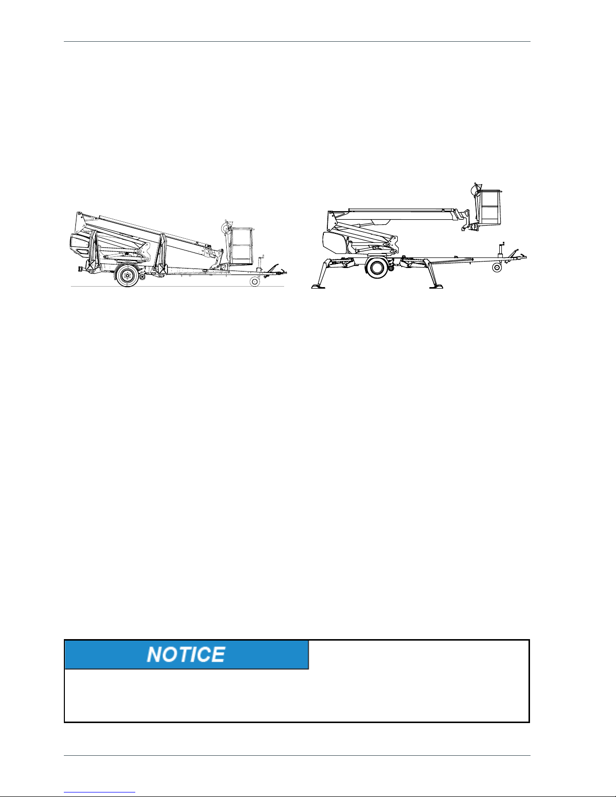
1.1. OVERVIEW OF THE UNIT
This unit is a trailer mounted, towable aerial work platform.
It is an aerial work platform, which complies with the EN280 type 1, where travelling is only
allowed with the platform in transport conguration.
For the operation the lift shall be supported by its hydraulic outriggers, extended so that the
wheels of the trailer lift off the ground.
1.2. INTENDED USE OF THE WORK PLATFORM
The aerial work platform is exclusively intended for transferring people and tools and acting
as a work platform within its permissible load-bearing capacity and reach (refer to the
“Technical Specications” table and the “Reach Diagram”).
The intended use also covers:
• Following all the instructions in the Operating Instructions
• Performance of the inspections and maintenance operations.
This aerial work platform is NOT insulated, and does not offer protection against contact with
electric current. The aerial work platform must not be used for work on electric systems.
Observe the safety instructions concerning the operating environment, and the restrictions
given in them,
The operator must receive instructions and consent from the manufacturer for all
such specic work methods or conditions that the manufacturer has not explicitly
dened in the unit's operation and maintenance instructions.
Nostimen ensisijaisena voimanlähteeenä on sähkömoottorikäyttö. The outriggers and the
boom system are hydraulically powered.
As an option, the lifts can be equipped with a driving device that can be controlled from the
ground.
Consult the chapters “Technical data" and “Structure and functions of the work platform" in
this manual for more detailed information about the lift.

9
2. TECHNICAL SPECIFICATIONS
135TB 150TB 180TB
Max. working height 13.5 m 15.0 m 18.0 m
Max. platform height 11.5 m 13.0 m 16.0 m
Max. outreach to the side 9.1 m 10.0 m 10.7 m
Boom rotation continuous
Platform rotation 90°
Turn area refer to the reach diagram
Support width 3.8 / 4.2 m 3.8 / 4.2 m 3.8 / 4.2 m
Transport width 1.78 m 1.78 m 1.78 m
Transport length 5.93 m 6.50 m 7.42 m
Transport height 2.16 m 2.24 m 2.19 m
Weight 1,765 kg 1835 kg 1945 kg
Max. allowed load on platform 215 kg
Max. number of persons + additional load 2 persons + 55 kg
Max. allowed sideways load (caused by persons) 400 N
Max. lateral inclination (chassis) ±0,3°
Max. wind speed during operation 12.5 m/s
Min. ambient temperature when working -20 °C
Max. support force on the outriggers 11,300 N 12,800 N 16800 N
Platform size 0,7 x 1,3 m
Gradeability 25%
Power supply
- powered by batteries 24V/3kW, 4x6V 235Ah
Sound pressure level 73 dB
Whole-body vibration Not detectable
- mains current, recharging batteries 230V/50Hz/10A
Socket outlets on the platform 2 x 230V/50Hz/10A
Battery voltage:
29.6V Charging voltage
25.46V
Voltage of batteries that are 100 % charged. Charger disconnected, the voltage has
been stabilizing for a few hours
20.88V
Voltage of 0 % charged batteries. Movements "Boom up" and "Telescope out"
impeded.
about 17 V All movements impeded
10
Operating instructions • DINO 135TB • 150TB • 180TB
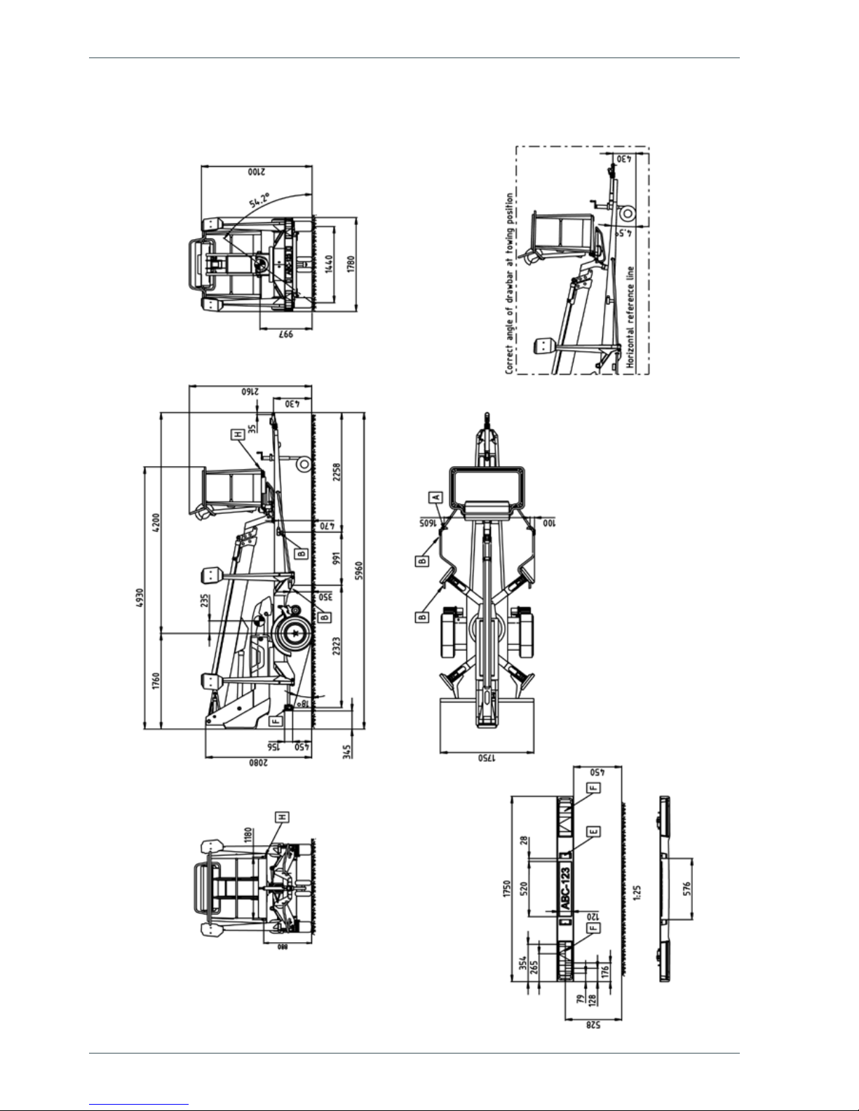
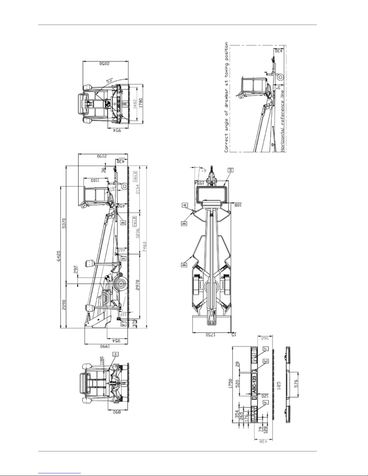
2.1. DIMENSION DRAWINGS
2.1.1. 135TB
11
2.1.2. 150TB
12
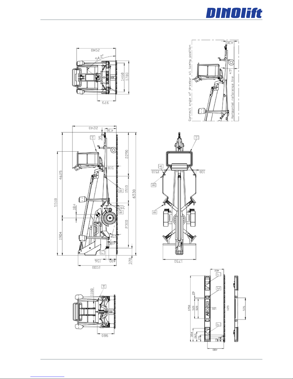
Operating instructions • DINO 135TB • 150TB • 180TB
2.1.3. 180TB
13
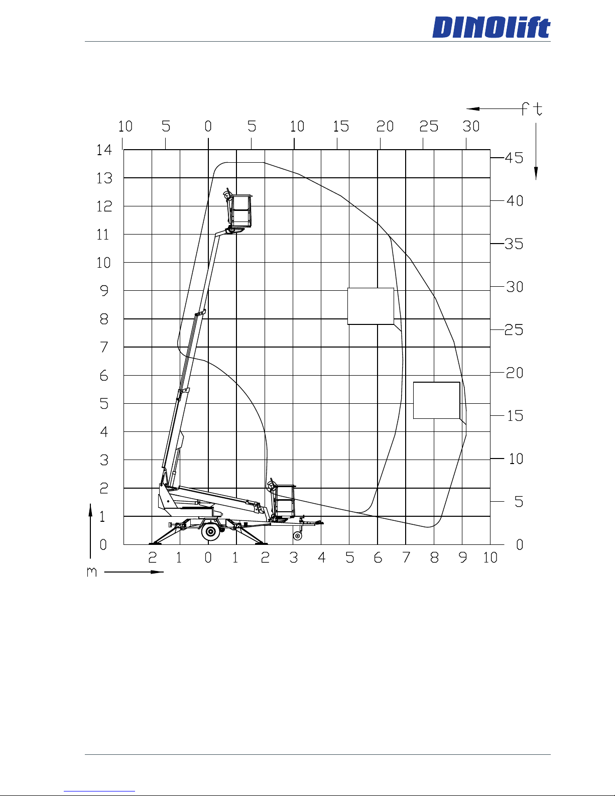
2.2. REACH DIAGRAM
2.2.1. 135TB
215KG
475LB
120KG
265LB
14
Operating instructions • DINO 135TB • 150TB • 180TB
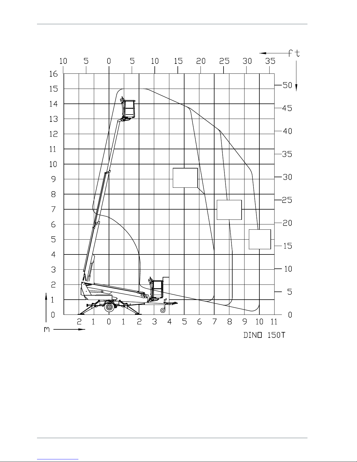
215KG
475LB
120KG
265LB
80KG
175LB
2.2.2. 150TB
15
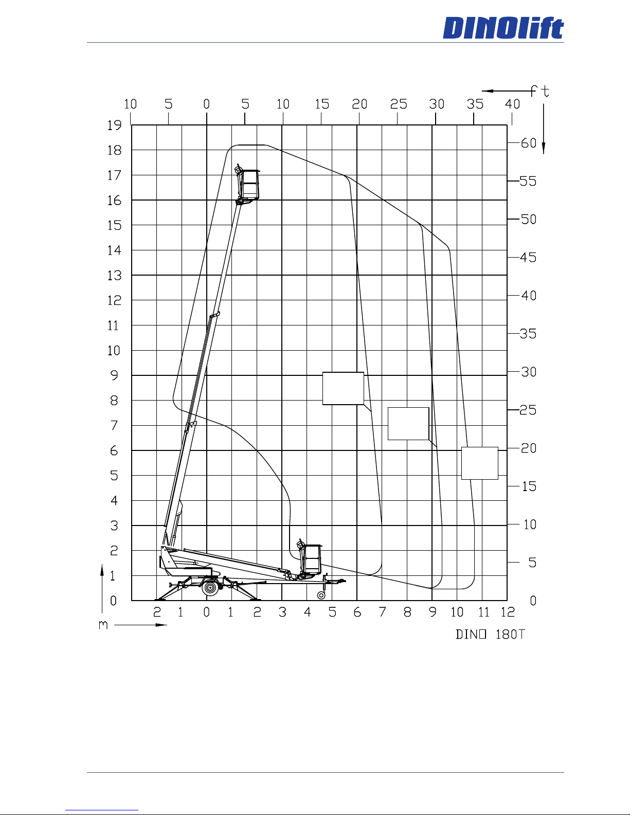
2.2.3. 180TB
215KG
475LB
120KG
265LB
80KG
175LB
16
Operating instructions • DINO 135TB • 150TB • 180TB
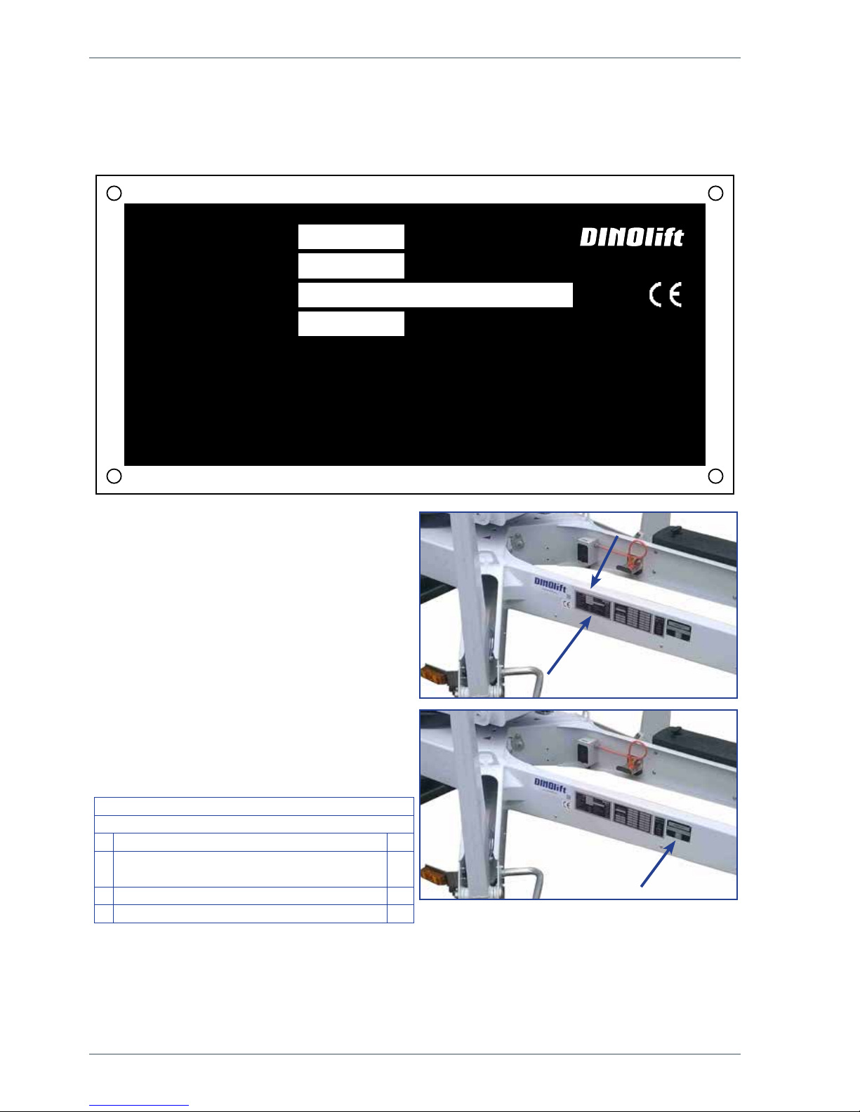
2.3. EXAMPLE OF THE MACHINE’S NAMEPLATE
The name of the manufacturer, and the production number and serial number of the machine
have been marked on the nameplate as shown in the picture below.
The nameplate of the lift is located on the
right-hand side of the tow-bar, as shown in
the picture.
The serial number is also engraved in the
lift's chassis, on the upper surface of the
right-hand tow-bar.
The nameplate of the trailer is located on
the tow-bar, on the right-hand side of the
nameplate of the lift, as shown in the picture.
Following data is written on the plate:
EU Type Approval Number (if available)
Serial number
Total weight kg
0
Maximum allowed weight on the towing
hitch
kg
1 Maximum allowed axle weight kg
2 kg
Raikkolantie 145
32210 Loimaa
FINLAND
400 N
230 V
-20 C
o
12,5 m/s
50 Hz
o
kg
kg
DINO
54.516
Serial number
Type Manufacturer
Year of manufacture Manufacturer's address
Voltage Frequency
Min. ambient temperature
when working
Maximum allowed wind speed
Weight kg Max. allowed load on platform
215
Maximum allowed sideways
load
Max. lateral inclination (chassis)
0.3
Maximum allowed number of
persons
Maximum allowed additional
load
2 55

17
2.4. EXAMPLE OF EU DECLARATION OF CONFORMITY
EU declaration of conformity for machine
Manufacturer
Dinolift Oy
Raikkolantie 145
FI-32210 Loimaa, FINLAND
declares that
DINO 150TB Aerial Work Platform no YGCD150TB F0150015
conforms to the provisions of the Machine Directive 2006/42/EC
as well as the national decree (VNA 400/2008), through which they have been brought
into effect
The inspection in accordance with Annex IX to the directive 2006/42/EC has been
carried out by the notied body no. 0537,
VTT
P.O.Box 1300
FI-33101 Tampere, FINLAND
has granted the certicate no. VTT 174/524/14
In addition, the aerial work platform also complies with the provisions of the following
European Directives:
2006/95/EC, 2000/14/EC, 2004/108/EC
In designing the machine, the following harmonised standards have been applied:
SFS-EN 280:2013, SFS-EN 60204-1/A1, SFS-EN-ISO 12100
The person, who has compiled the technical construction le: Santtu Siivola
Chief Engineer
Dinolift Oy, Raikkolantie 145,
FI-32210 Loimaa, FINLAND
Loimaa 07.01.2015
----------------------------------------Santtu Siivola
Chief Engineer
18
Operating instructions • DINO 135TB • 150TB • 180TB
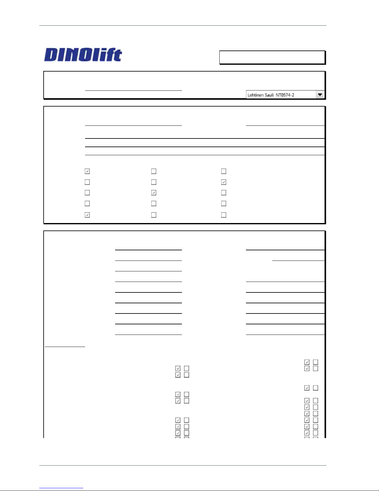
2.5. SAMPLE OF INSPECTION PROTOCOL FOR THE ACCESS PLATFORM
TEST CERTIFICATE
DATE:
START-UP TESTS:
Inspection place:
Dinolift Oy Inspector's signature:
BASIC KNOWLEDGE
Manufacturer:
Dinolift OY Place of manufacture: Finland
Address:
Raikkolantie 145
32210 LOIMAA
Importer:
Type of lift:
Chassis:
Boom:
Outriggers:
TECHNICAL SPECIFICATION
Machine and type:
DINO 150 TB Max. platform height 13m
Number of manufacture
YGCD150TB F015 Max. outreach: depend on load: Depend on load
Year of manufacture
2015
Max. lifting capacity:
215 kg Boom rotation: Continuous
Max. person number:
2 Support width: 3,80 m
Max. additional load:
55kg Transport width: 1,78 m
Power supply:
24 VDC Transport length: 6,43 m
Lowest temperature:
-20 °C Transport height: 2,14 m
Weight:
1835 kg Basket size: 0,7x1,3 m
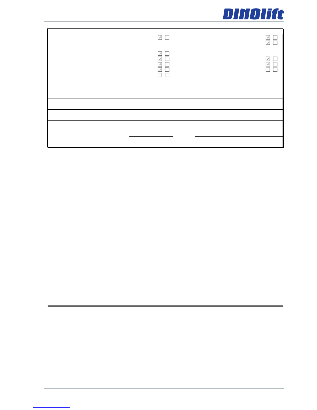
Inspection points: (Y = meet standards N = do not meet standards)
Y
N Y N
A. STRENGTH 6. Plate for supports
1. Certificate of material 7. Safety colours
2. Certificate of strength
D. SAFETY REQUIREMENTS
B. STABILITY 1. Indicating device for horizontal
1. Certificate of stability test position
2. Working space diagram 2. Locking device and lockings
3. Stop device for lifting
C. GENERAL REQUIREMENTS 4. Stop for opening of support
1. User's manual 5. Safety distances
2. Place for safekeeping for user's manual 6. Position of working face
3. Machine plate - checking plate 7. Structure of working face
www.dinolift.com
Boom platform Scissor platform Mast platform
Car Self propelled Trailer mounted
Articulated boom Telescope boom Articulated telescope boom
Scissor Fixed mast Telescope mast
Hydraulic turning Hydraulic pushing Mechanical
19
The initial inspection and test loading of the Dino aerial work platforms is performed by the
manufacturer. A protocol, drawn up during the inspection, will accompany the lift.
The protocols of the start-up and periodic inspections must be kept with the lift or its
immediate proximity for at least ve years.
E. ELECTRIC APPLIANCES G. SAFETY DEVICE
1. Electric appliances 1. Safety limit switch
2. Sound signal
F. CONTROL DEVICES
1. Protections H. LOADING TEST
2. Symbols / directions 1. Overload test = 323 kg (150%)
3. Placings 2. Funktional test = 237 kg (110%)
4. Emergency stop
FAILINGS AND NOTES
Failings have been repaired. Date: Signature:
Dinolift Oy
Raikkolantie 145
FIN-32210 LOIMAA, FINLAND
Tel. +358 - 20 - 1772 400, Fax +358 - 2 - 7627 160, e-mail: info@dinolift.com
20
Operating instructions • DINO 135TB • 150TB • 180TB
3. SAFETY
All the essential safety instructions and warnings, relevant to transport, use and maintenance
of the lift, are described in this chapter.
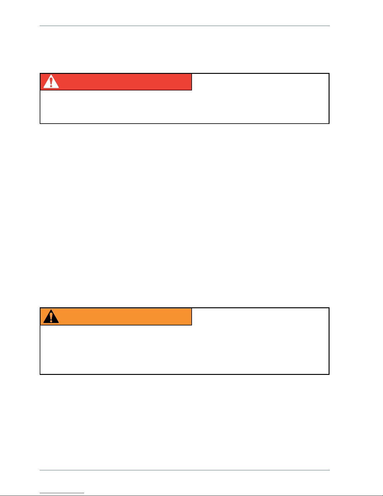
DANGER
Failure to observe these instructions and safety regulations may cause a severe injury or
even death. Familiarise yourself with all the safety regulations, operating instructions and
signs afxed to the machine, and follow them.
Make sure that you understand all the safety instructions and regulations. Also make sure
that others operating the machine or working on the work platform are familiar with these
instructions.
3.1. SAFETY INSTRUCTIONS
Only specially trained personnel with authorisation in writing, who are well familiarised with
the device, and at least 18-years old, are allowed to operate the unit.
Keep the lift free of any dirt, which may impair safe operation, and impede the inspection of
the structures.
The device must be serviced and inspected regularly.
Only skilled persons, familiar with the service and repair instructions for the lift, are allowed
to carry out servicing and repair work.
It is strictly prohibited to use a lift which is out of order.
Never remove or disable any safety devices of the machine.
DANGER
WARNING
The device must neither be altered without the manufacturer’s consent nor be used under
conditions, which do not meet the manufacturer's requirements.
The operator must be given instructions and consent from the manufacturer for all such
specic work methods or conditions that the manufacturer has not explicitly dened.

21
TRANSFERS
Observe the maximum allowed gradient when transferring the lift. During transfer in rough
terrain, always try to position yourself higher than the machine.
Beware of xed or moving obstacles in the terrain or near the lift while driving. Make sure
that you have a clear view of the driving path.
WORK AREA AND PREPARATIONS BEFORE LIFTING WORK
When working in busy areas, the operating range of the lift must be clearly marked by using
either warning lights or fencing.
Also observe the regulations of the Road Trafc Act.
Ensure the unobstructed range of movement before operating the outriggers.
The load-bearing capacity and the gradient of the base must be taken into account when
supporting the chassis.
Ensure that the outriggers cannot slide while on a gradient.
Additional support plates of adequate size must be used under the outriggers, when working
on soft ground. Only use such additional support plates, on which the metallic outriggers will
not slide.
While in the support position, ensure that the wheels are off the ground.
Always verify the horizontal position of the machine.
Always ensure that the work area is clear of outsiders. Danger of getting squeezed between
rotating and xed structures.
While operating the boom from the control centre on the turning device, beware of
getting pressed against the outriggers or other structures that do not turn with the
boom.
 Loading...