

Dinolift DINO 120TB, DINO 120T Operating Instructions Manual

OPERATING
INSTRUCTIONS
DINO 120T • 120TB
Dealer:Manufacturer:
Dinolift Oy
Raikkolantie 145
FI-32210 LOIMAA
Tel. + 358 20 1772 400
info@dinolift.com
www.dinolift.com


3
TRANSLATION OF THE ORIGINAL INSTRUCTIONS
Valid from serial number
120T 120328, 120330 -->
120TB 60001 -->

4
Operating instructions • DINO 120T • 120TB
CONTENTS
1. TO THE OPERATOR ................................................................................................... 7
1.1. OVERVIEW OF THE UNIT .................................................................................. 8
1.2. INTENDED USE OF THE WORK PLATFORM ................................................... 8
2. TECHNICAL SPECIFICATIONS .................................................................................9
2.1. DIMENSION DRAWING .................................................................................... 10
2.2. REACH DIAGRAM ............................................................................................ 11
2.3. EXAMPLE OF THE MACHINE’S NAMEPLATE ................................................ 12
2.4. EXAMPLE OF EU DECLARATION OF CONFORMITY .................................... 13
2.5. SAMPLE OF INSPECTION PROTOCOL FOR THE ACCESS PLATFORM ..... 14
3. SAFETY ..................................................................................................................... 16
3.1. SAFETY INSTRUCTIONS .................................................................................16
3.2. SAFETY-RELATED NOTIFICATIONS ............................................................... 20
3.3. SAFETY DEVICES ............................................................................................ 21
4. STRUCTURE AND FUNCTIONS OF THE WORK PLATFORM ............................... 24
4.1. STRUCTURE OF THE WORK PLATFORM ...................................................... 24
4.2. FUNCTIONS OF THE WORK PLATFORM ....................................................... 25
4.3. OPERATING CONTROLS FOR THE FUNCTIONS .......................................... 26
4.3.1. 120T Operating controls in the chassis control centre ................................................. 26
4.3.2. 120TB Operating controls in the chassis control centre .............................................. 27
4.3.3. Operating controls for the outriggers ........................................................................... 28
4.3.4. Operating controls in the platform control centre ......................................................... 29
5. OPERATING INSTRUCTIONS .................................................................................. 30
5.1. START-UP ......................................................................................................... 30
5.1.1. Worksite inspection ...................................................................................................... 30
5.1.2. Positioning the lift .........................................................................................................31
5.1.3. Starting up ...................................................................................................................32
5.1.4. Supporting the lift ......................................................................................................... 34
5.2. OPERATION ......................................................................................................35
5.2.1. Operating the lift from the chassis control centre ........................................................35
5.2.2. Operating the lift from the platform control centre .......................................................36
5.2.3. Special instructions for winter use ............................................................................... 38
5.2.4. Ending the work ........................................................................................................... 38
5.3. TRANSFERRING THE LIFT .............................................................................. 39
5.3.1. Preparing the lift for transport ......................................................................................39
5.3.2. Using the driving device ...............................................................................................40
5.3.3. Towing the lift ............................................................................................................... 42
5.3.4. Lifting the device .......................................................................................................... 43

5
5.4. LONG-TERM STORAGE ..................................................................................44
5.5. IN CASE OF EMERGENCY .............................................................................. 46
5.5.1. When at risk of losing the stability ...............................................................................46
5.5.2. In case of overloading ..................................................................................................46
5.5.3. In case the power supply is interrupted ....................................................................... 46
5.5.4. In case of malfunction, when even the emergency descent system is not operational 47
6. INSTRUCTIONS FOR FAULT-FINDING ...................................................................48
7. MAINTENANCE SCHEDULE .................................................................................... 52
7.1. SCHEDULE FOR INSPECTIONS REQUIRED BY THE AUTHORITIES .......... 54
7.2. LUBRICATION PLAN ........................................................................................ 55
8. ROUTINE MAINTENANCE DURING OPERATION .................................................. 56
8.1. INSTRUCTIONS FOR DAILY MAINTENANCE AND INSPECTIONS .............. 57
8.1.1. Check the condition of chassis, the boom and the work platform ................................57
8.1.2. Check the tyres and tyre pressure ............................................................................... 57
8.1.3. Check the lights ...........................................................................................................57
8.1.4. Check the hydraulic oil level ........................................................................................57
8.1.5. Check the hydraulic hoses, pipes and connectors ......................................................57
8.1.6. Check the operation of the safety limit switches .......................................................... 58
8.1.7. Check the operation of the emergency descent, the emergency stop and the
sound signal .................................................................................................................58
8.1.8. Decals, plates and instructions .................................................................................... 58
8.2. MAINTENANCE OF THE BATTERIES ............................................................. 59
9. CHANGE OF OWNER ...............................................................................................63

6
Operating instructions • DINO 120T • 120TB
BLANK
7
1. TO THE OPERATOR
Keep this manual on the work platform of the lift in the box reserved for it. If the instruction
manual gets lost, damaged, or for some other reason becomes unreadable, order a new
manual from the manufacturer.
This manual is intended to familiarise the user with the structure and functions of the work
platform, as well as with its appropriate use. The manual provides guidance on the service
measures that are the responsibility of the user of the work platform.
Other maintenance procedures on the work platform require special skills, special tools or
accurate knowledge about measurements or adjusted values. Guidance for these measures
is provided in a separate service manual. For situations that require service or repair
measures, contact the authorised service provider, importer or manufacturer.
DANGER
Read all the instructions in this manual before using the aerial work platform. Make sure that
you have understood all the instructions. The instructions must absolutely be followed during
operation and maintenance of the aerial work platform.
When handling the unit, in addition to the instructions in this manual, the user must also
observe the local legislation, the guidelines stipulated by the employer, and regulations valid
at the work site.
Dinolift Oy is constantly developing its products. For this reason, the contents of this manual
might not always be in full compliance with the most recent version of the product. Dinolift Oy
reserves the right to modify the product without prior notice. Dinolift Oy assumes no liability
for any problems caused by changed or missing data or mistakes in this manual.
Please consult your dealer or the manufacturer for more information and detailed
instructions.
8
Operating instructions • DINO 120T • 120TB
1.1. OVERVIEW OF THE UNIT
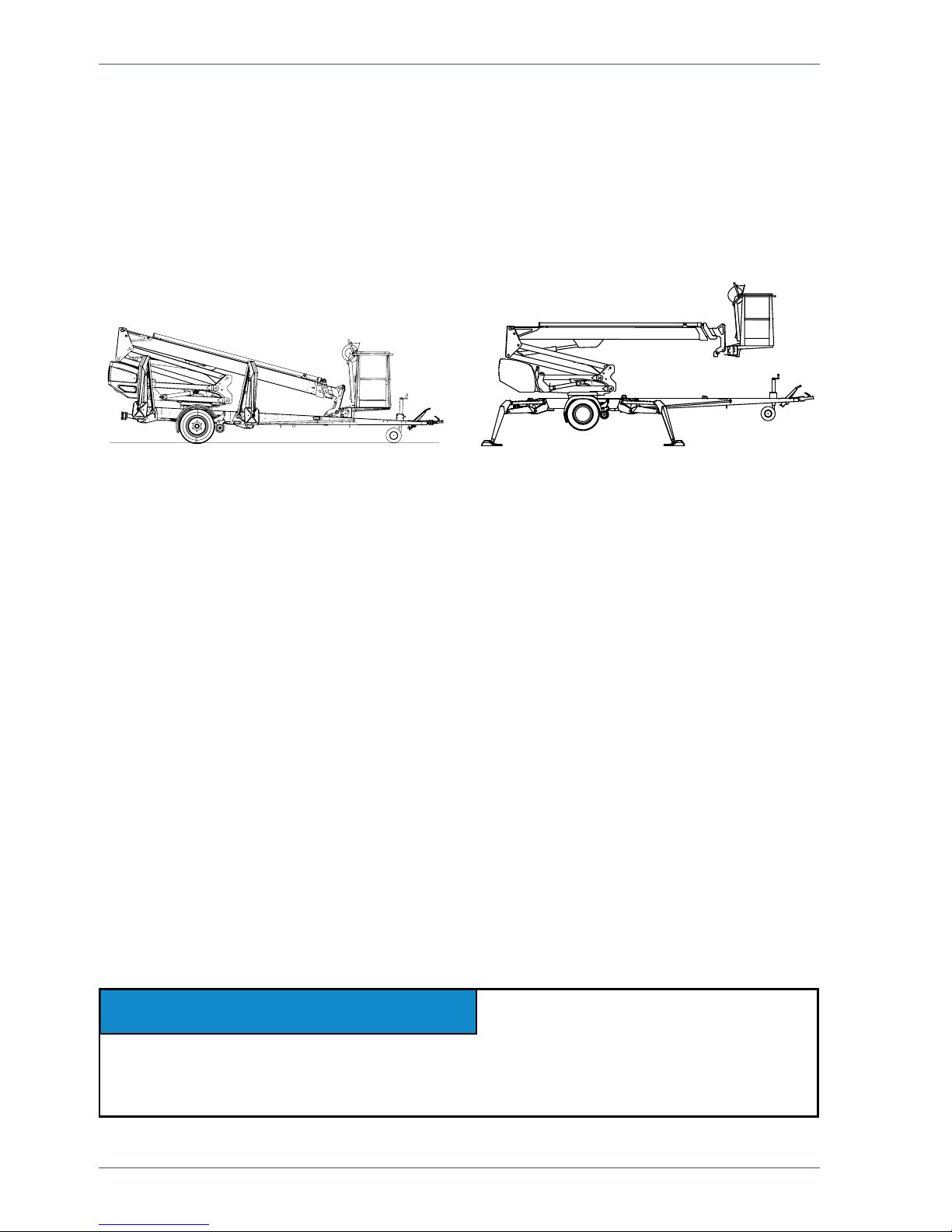
This unit is a trailer mounted, towable aerial work platform.
It is an aerial work platform, which complies with the EN280 type 1, where travelling is only
allowed with the platform in transport conguration.
For the operation the lift shall be supported by its hydraulic outriggers, extended so that the
wheels of the trailer lift off the ground.
1.2. INTENDED USE OF THE WORK PLATFORM
The aerial work platform is exclusively intended for transferring people and tools and acting
as a work platform within its permissible load-bearing capacity and reach (refer to the
“Technical Specications” table and the “Reach Diagram”).
The intended use also covers:
• Following all the instructions in the Operating Instructions
• Performance of the inspections and maintenance operations.
This aerial work platform is NOT insulated, and does not offer protection against contact with
electric current. The aerial work platform must not be used for work on electric systems.
Observe the safety instructions concerning the operating environment, and the restrictions
given in them,
DANGER
WARNING
CAUTION
NOTICE
The operator must receive instructions and consent from the manufacturer for all
such specic work methods or conditions that the manufacturer has not explicitly
dened in the unit's operation and maintenance instructions.
The primary power source of the lift is electric motor. The outriggers and the boom system
are hydraulically powered.
As an option, the lifts can be equipped with a driving device that can be controlled from the
ground.
Consult the chapters “Technical data" and “Structure and functions of the work platform" in
this manual for more detailed information about the lift.

9
2. TECHNICAL SPECIFICATIONS
120T 120TB
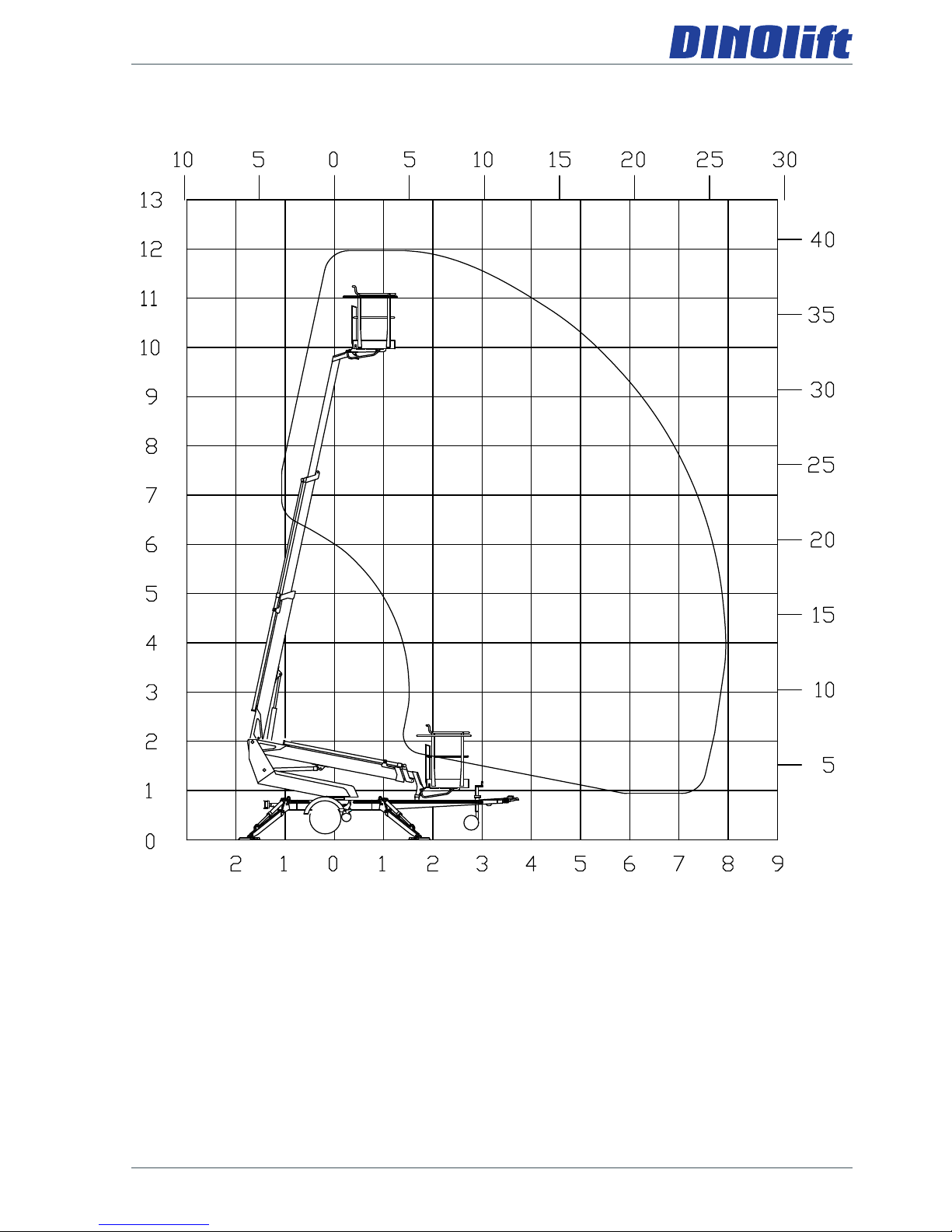
Max. working height 12,0 m
Max. platform height 10,0 m
Max. outreach 7,9 m
Boom rotation continuous
Platform rotation Turn area refer to the reach diagram
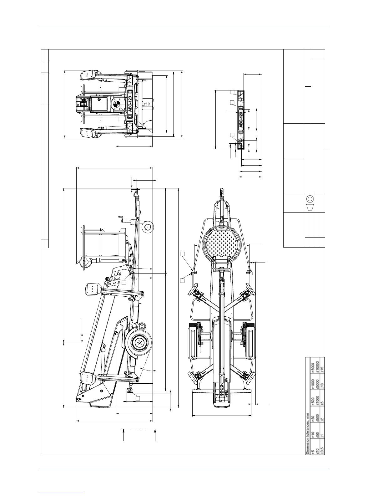
Support width 3,15 / 3,55 m
Transport width 1,72 m
Transport length 5,56 m
Transport height 1,95 m
Weight 1285 kg 1360 kg
Max. allowed load on platform 120 kg 130 kg
Max. number of persons + additional load 1 person + 40 kg 1 person + 50 kg
Max. allowed sideways load (caused by persons) 200 N
Max. lateral inclination (chassis) ±0,3°
Max. allowed gradient of ground to the side 4,0°
Max. allowed gradient of ground lengthwise 4,0°
Max. wind speed during operation 12,5 m/s
Min. ambient temperature when working - 20 °C
Max. support force on the outriggers 9500 N
Platform size 0,7 x 0,8 m / Ø 0,85 m
Gradeability 0,25
Socket outlets on the platform 2 x 230V/50Hz/10A
Power supply Mains current Battery powered
230V/50Hz/10A
24V/2kW /
2x12V 140 Ah
Sound pressure level < 70 dB < 70 dB
Whole-body vibration Not detectable Not detectable
Battery charging, mains current - 230V/50Hz/10A
Honda GX200SXE
Fuel Petrol
Net power 4.1 kW (5,5 hp)
Fuel tank volume 3,1 l
Oil volume 0,6 l
Fuel consumption 1,7 l/h
Sound pressure level 98 dB
Whole-body vibration < 0,5 m/s2
Optional engines - 120T
10
Operating instructions • DINO 120T • 120TB
2.1. DIMENSION DRAWING
3905
156
2162
1880
430
1665
241
923
5570
2000
455
550
533
373
2968
3°
21°
35
A
A
G
G
Horizontal reference line
1710
1730
"normal" position
1635
1440
923
52°
100
1490
1410
150
A
G
1490
578
520
120
455
79
146
59
220
508
511
552
573
SECTION A-A
C D
E
Rev.
Muutos
Pvm.
Muut
Hyv
MITTAPIIRROS
DINO 120T
1773,95
1:25
3CB4160
Uusi
Ent.
Liittyy
Tuote
Mittakaava
Yleistoleranssit
Massa
Hyv.
Suunn.
Piirt.
DINO Lift
SFS-EN 22768-1
14.03.2007
JR
11
2.2. REACH DIAGRAM
12
Operating instructions • DINO 120T • 120TB
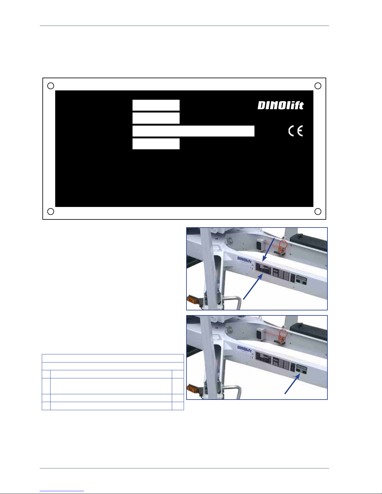
2.3. EXAMPLE OF THE MACHINE’S NAMEPLATE
The name of the manufacturer, and the production number and serial number of the machine
have been marked on the nameplate as shown in the picture below.
The nameplate of the lift is located on the
right-hand side of the tow-bar, as shown in
the picture.
The serial number is also engraved in the
lift's chassis, on the upper surface of the
right-hand tow-bar.
The nameplate of the trailer is located on
the tow-bar, on the right-hand side of the
nameplate of the lift, as shown in the picture.
Following data is written on the plate:
EU Type Approval Number (if available)
Serial number
Total weight kg
0
Maximum allowed weight on the towing
hitch
kg
1 Maximum allowed axle weight kg
2 kg
Raikkolantie 145
32210 Loimaa
FINLAND
400 N
230 V
-20 C
o
12,5 m/s
50 Hz
o
kg
kg
DINO
54.1079
Serial number
Type Manufacturer
Year of manufacture Manufacturer's address
Voltage Frequency
Min. ambient temperature
when working
Maximum allowed wind speed
Weight kg Max. allowed load on platform
120
Maximum allowed sideways
load
Max. lateral inclination (chassis)
0.3
Maximum allowed number of
persons
Maximum allowed additional
load
1 40

13
2.4. EXAMPLE OF EU DECLARATION OF CONFORMITY
EU declaration of conformity for machine
Manufacturer
Dinolift Oy
Raikkolantie 145
FI-32210 Loimaa, FINLAND
declares that
DINO 120T Aerial Work Platform no YGC0D120TG0120312
conforms to the provisions of the Machine Directive 2006/42/EC
as well as the national decree (VNA 400/2008), through which they have been brought
into effect
The inspection in accordance with Annex IX to the directive 2006/42/EC has been
carried out by the notied body no. 0044,
TÜV NORD CERT GmbH
Langemarkstraβe 20
DE-45141 Essen
has granted the certicate no. TÜV 44205 14 195 701
In addition, the aerial work platform also complies with the provisions of the following
European Directives:
2006/95/EC, 2000/14/EC, 2004/108/EC
Measured sound power level L
wa
( 99 + 1,5 ) 100,5 dB
Guaranteed sound power level L
wa
100,5 + 0,5 dB
To the assessment procedure of conformity has been applied: 2000/14/EC, Annex V:
Internal control of production.
In designing the machine, the following harmonised standards have been applied:
SFS-EN 280:2013, SFS-EN 60204-1/A1, SFS-EN-ISO 12100
The person, who has compiled the technical construction le: Santtu Siivola
Chief Engineer
Dinolift Oy, Raikkolantie 145,
FI-32210 Loimaa, FINLAND
Loimaa 5.2.2016
----------------------------------------Antti Tuura
Foreman
14
Operating instructions • DINO 120T • 120TB
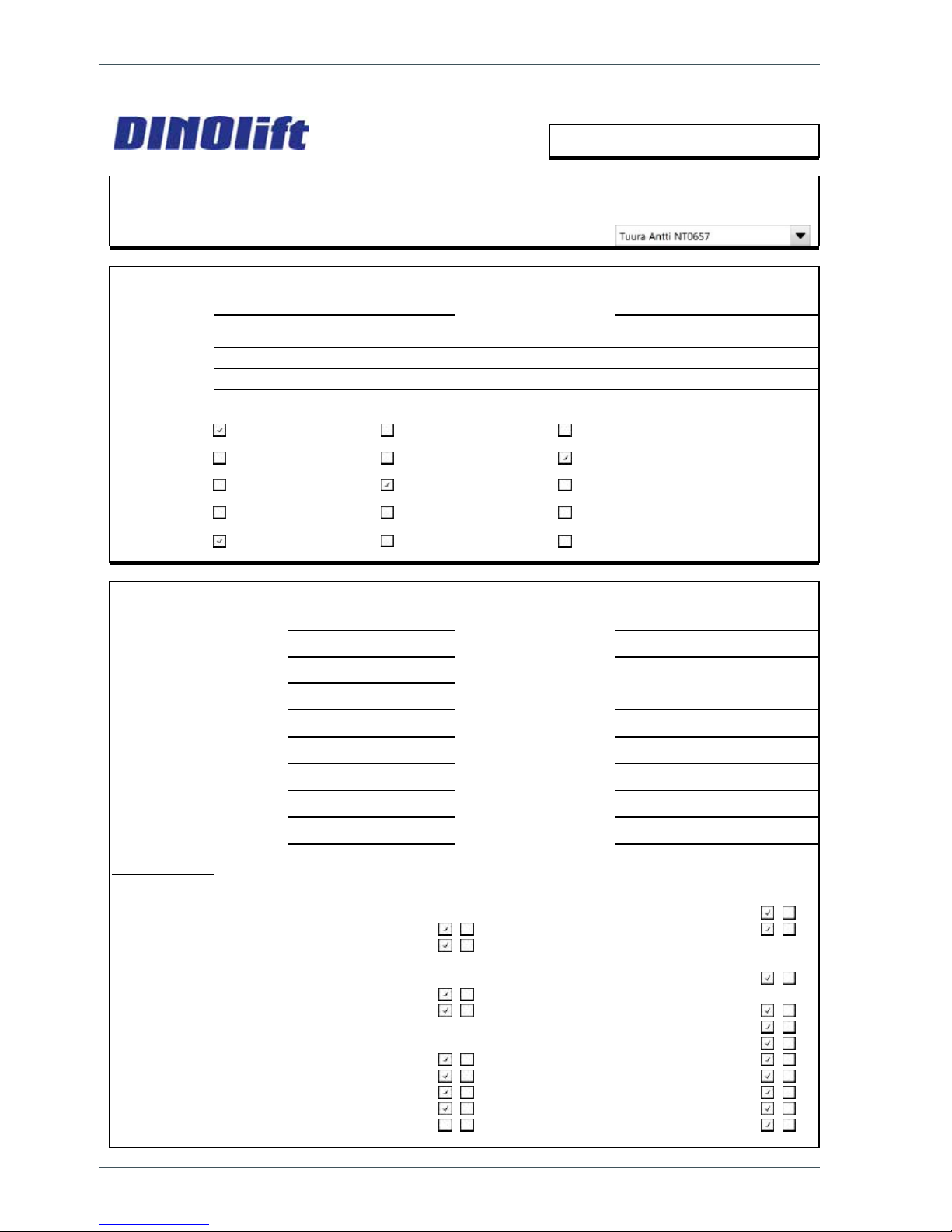
2.5. SAMPLE OF INSPECTION PROTOCOL FOR THE ACCESS PLATFORM
TEST CERTIFICATE
DATE:
28.1.2016
START-UP TESTS:
Inspection place: Dinolift O
y
Inspector's signature:
BASIC KNOWLEDG
E
Manufacturer: Dinolift OY Place of manufacture: Finland
Address: Raikkolantie 145
32210 LOIMA
A
Importer:
Type of lift:
Chassis:
Boom:
Outriggers:
TECHNICAL SPECIFICATION
S
Machine and type: DINO 120 T Max. platform height 10,0 m
Number of manufacture YGC0D120TG0120313 Max. outreach:
d
7,9 m
Year of manufacture 2016
Max. lifting capacity: 120 kg Boom rotation: Continuous
Max. person number: 1 Support width: 3,9x3,6 m
Max. additional load: 40kg Transport width: 1,71 m
Power supply: 230VA
C
Transport length: 5,52 m
Lowest temperature: -20 °C Transport height: 1,96 m
Weight: 1285 kg Basket size: (ø) 0,85 m
Inspection points:
(Y = meet standards N = do not meet standards)
Y N Y N
A. STRENGTH 6. Plate for supports
1. Certificate of material 7. Safety colours
2. Certificate of strength
D. SAFETY REQUIREMENTS
B. STABILITY 1. Indicating device for horizontal
1. Certificate of stability test position
2. Working space diagram 2. Locking device and lockings
3. Stop device for lifting
C. GENERAL REQUIREMENTS 4. Stop for opening of support
1. User's manual 5. Safety distances
2. Place for safekeeping for user's manual 6. Position of working face
3. Machine plate - checking plate 7. Structure of working face
4. Load plate 8. Emergency descent system
5. Warning plate 9. Limit devices
www.dinolift.com
Boom platform Scissor platform Mast platform
Car Self propelled Trailer mounted
Articulated boom Telescope boom Articulated telescope boom
Scissor Fixed mast Telescope mast
Hydraulic turning Hydraulic pushing Mechanical

15
The initial inspection and test loading of the Dino aerial work platforms is performed by the
manufacturer. A protocol, drawn up during the inspection, will accompany the lift.
The protocols of the start-up and periodic inspections must be kept with the lift or its
immediate proximity for at least ve years.
ECIVED YTEFAS .GSECNAILPPA CIRTCELE .E
hctiws timil ytefaS .1secnailppa cirtcelE .1
2. Sound signal
F. CONTROL DEVICES
TSET GNIDAOL .HsnoitcetorP .1
)%051( gk 081 = tset daolrevO .1snoitcerid / slobmyS .2
)%011( gk 231= tset lanoitknuF .2sgnicalP .3
4. Emergency stop
FAILINGS AND NOTES
:erutangiS:etaD.deriaper neeb evah sgniliaF
Dinolift O
y
Raikkolantie 145
FIN-32210 LOIMAA, FINLAND
Tel. +358 - 20 - 1772 400, Fax +358 - 2 - 7627 160, e-mail: dino@dinolift.com
16
Operating instructions • DINO 120T • 120TB
3. SAFETY
All the essential safety instructions and warnings, relevant to transport, use and maintenance
of the lift, are described in this chapter.
DANGER
Failure to observe these instructions and safety regulations may cause a severe injury or
even death. Familiarise yourself with all the safety regulations, operating instructions and
signs afxed to the machine, and follow them.
Make sure that you understand all the safety instructions and regulations. Also make sure
that others operating the machine or working on the work platform are familiar with these
instructions.
3.1. SAFETY INSTRUCTIONS
Only specially trained personnel with authorisation in writing, who are well familiarised with
the device, and at least 18-years old, are allowed to operate the unit.
Keep the lift free of any dirt, which may impair safe operation, and impede the inspection of
the structures.
The device must be serviced and inspected regularly.
Only skilled persons, familiar with the service and repair instructions for the lift, are allowed
to carry out servicing and repair work.
It is strictly prohibited to use a lift which is out of order.
Never remove or disable any safety devices of the machine.
DANGER
WARNING
The device must neither be altered without the manufacturer’s consent nor be used under
conditions, which do not meet the manufacturer's requirements.
The operator must be given instructions and consent from the manufacturer for all such
specic work methods or conditions that the manufacturer has not explicitly dened.

17
TRANSFERS
Observe the maximum allowed gradient when transferring the lift. During transfer in rough
terrain, always try to position yourself higher than the machine.
Beware of xed or moving obstacles in the terrain or near the lift while driving. Make sure
that you have a clear view of the driving path.
WORK AREA AND PREPARATIONS BEFORE LIFTING WORK
When working in busy areas, the operating range of the lift must be clearly marked by using
either warning lights or fencing.
Also observe the regulations of the Road Trafc Act.
Ensure the unobstructed range of movement before operating the outriggers.
The load-bearing capacity and the gradient of the base must be taken into account when
supporting the chassis.
Ensure that the outriggers cannot slide while on a gradient.
Additional support plates of adequate size must be used under the outriggers, when working
on soft ground. Only use such additional support plates, on which the metallic outriggers will
not slide.
While in the support position, ensure that the wheels are off the ground.
Always verify the horizontal position of the machine.
Always ensure that the work area is clear of outsiders. Danger of getting squeezed between
rotating and xed structures.
While operating the boom from the control centre on the turning device, beware of
getting pressed against the outriggers or other structures that do not turn with the
boom.
18
Operating instructions • DINO 120T • 120TB
LIFTING AND WORKING ON THE PLATFORM
Never exceed the maximum number of persons, maximal loading or lateral force, allowed for
the lift. Never add load onto the platform while in the upper position.
Before operating, always ensure that the safety devices and the emergency descent system
are in working order.
Never use a lift alone. Make sure that there is always someone on the ground, who can call
for help in case of an emergency.
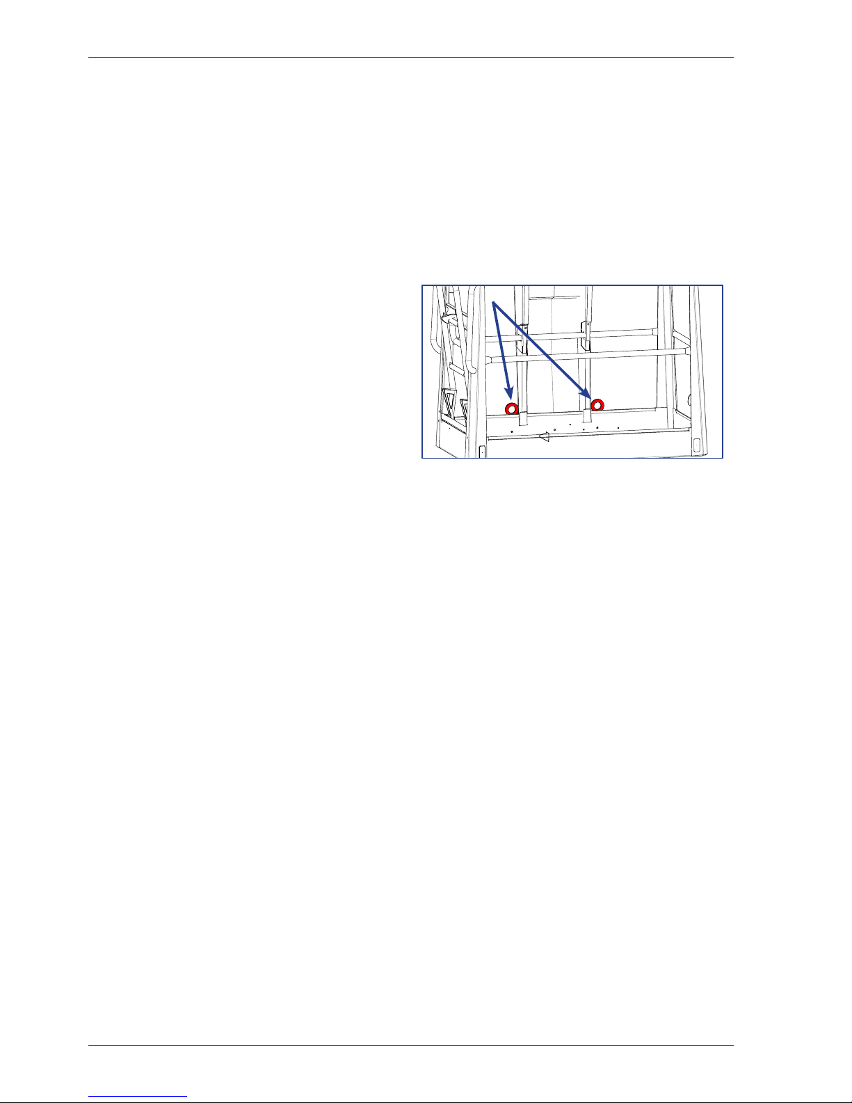
Use the safety harness! Fix the safety
harness to the xing points, intended for the
purpose.
Note! The platform is tted with a xing point
for the safety harness of each user. Only one
harness per xing point.
Do not use ladders, steps or other similar
equipment on the platform.
Never throw or drop any objects from the platform.
The lift must not be used as a crane.
The lift must not be used for transferring goods or persons between different oors or
working levels. Stepping on or off the platform in motion is prohibited.
When the boom is in its lowest positions, make sure it cannot clash during rotation with
structures that do not turn with the boom.
Always make sure, before lowering the platform, that the area under it is clear.
Avoid damaging the platform by lowering it on the ground, or bringing it in contact with any
structures.

19
OPERATING CONDITIONS
The weather conditions, such as wind, visibility and rain, must always be taken into account
so that these will not adversely affect the safe performance of the lifting operations.
The use of the lift is prohibited, if
the temperature drops under -20 °C or
the wind speed exceeds 12.5 m/s
Wind speed ( m/s) Conditions on land
0 Calm Smoke rises vertically
1-3 Light breeze
Smoke moves with the wind and the wind feels on exposed
skin. Leaves rustle.
4-7 Gentle breeze
Leaves and small branches of trees are moving. Flag is
ying. Wind lifts dust and loose pieces of paper from the
ground.
8-13 Strong breeze
Small broad-leaved trees and large branches sway. Wind
whistles as it hits houses or other xed objects. Umbrella is
difcult to use.
14-16 Strong
All the trees are swaying. It is difcult. to walk against the
wind.
Do not take tools/material of large surface area onto the platform. The increase in wind load
may jeopardize the stability of the device.
Beware of the live aerial power lines in the area – observe the minimum
safety distances:
Voltage Min. distance below (m) Min. distance at the side (m)
100-400 V hanging spiral cable 0.5 0.5
100 400 V open-wire cable 2 2
6-45 kV 2 3
110 kV 3 5
220 kV 4 5
400 kV 5 5
20
Operating instructions • DINO 120T • 120TB
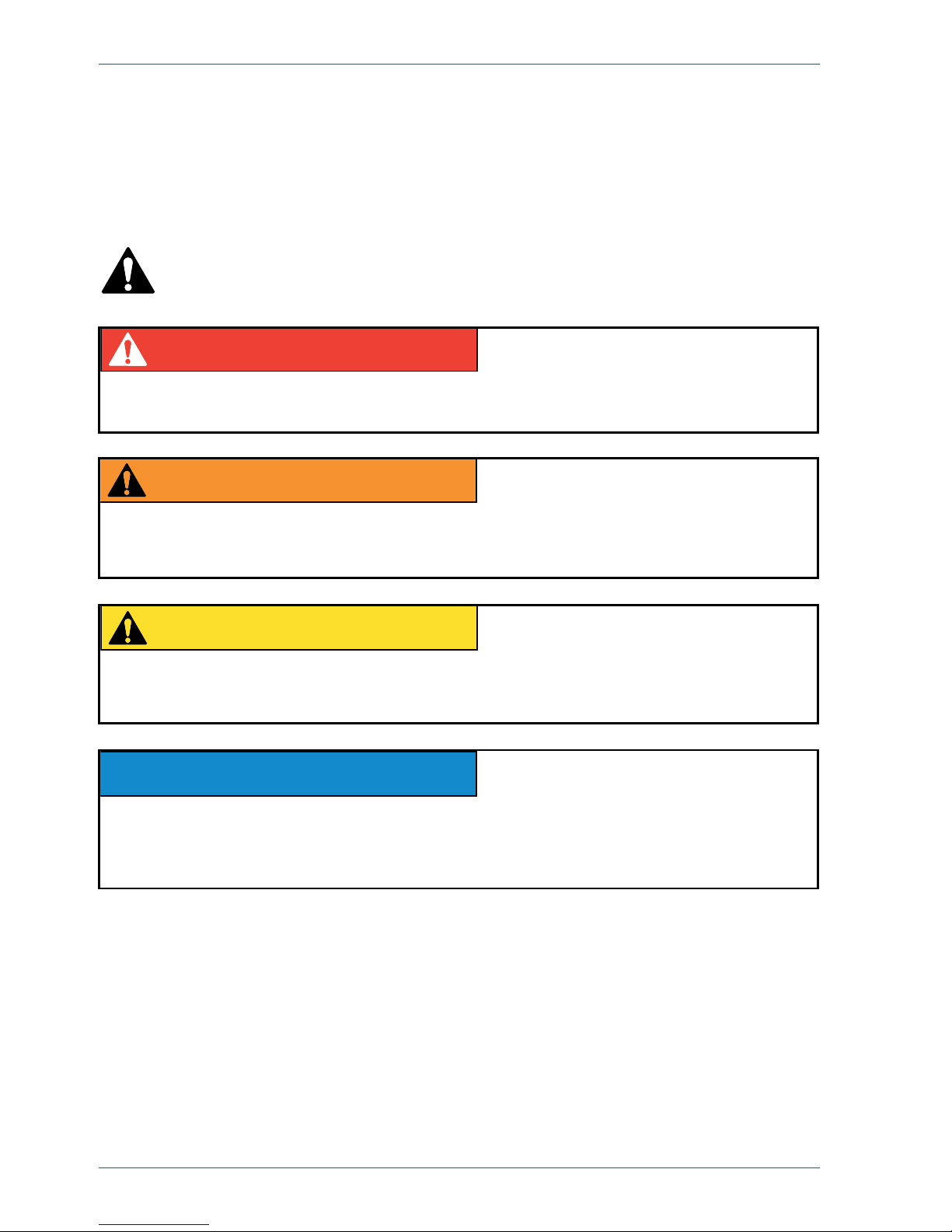
3.2. SAFETY-RELATED NOTIFICATIONS
The following safety alert symbols and safety signal words are used in this manual and in
safety labels.
Observe all the safety instructions that follow these symbols, in order to avoid dangerous
situations and personal injuries.
This is a general safety alert symbol and it is used to alert you about a potential
hazard. Observe the additional instructions given in form of text or symbols that
follow this symbol.
DANGER
Red DANGER-message warns for an imminent or potential hazardous situation which, if not
avoided, may result in death or serious injury.
DANGER
WARNING
Orange WARNING -message is used in connection with potential risk factors, which if not
avoided, under certain conditions, may result in death or serious injury.
DANGER
WARNING
CAUTION
Yellow CAUTION -message is used to warn about a hazardous situation which, if not
avoided, could result in minor or moderate injury.
DANGER
WARNING
CAUTION
NOTICE
Blue notice-message is used to draw your attention to special notications or instructions
that are related to the operation or maintenance. Such messages include, for example,
instructions that are related to reliability of the machine or aim to avoid material losses.
 Loading...