

Dinolift DINO 105TL Operating Instructions Manual

OPERATING
INSTRUCTIONS
DINO 105TL
Manufacturer:
Dinolift Oy
Raikkolantie 145
FI-32210 LOIMAA
Tel. + 358 20 1772 400
info@dinolift.com
www.dinolift.com
Dealer:

DINO 105TL
2

DINO 105TL
3
ORIGINAL OPERATING INSTRUCTIONS
Valid from serial number 10196

DINO 105TL
4
TABLE OF CONTENTS
OPERATING AND SAFETY INSTRUCTIONS ...................................................................... 7
1 EU DECLARATION OF CONFORMITY .......................................................................... 7
2 REACH DIAGRAM .......................................................................................................... 8
3 DIMENSION DRAWING .................................................................................................. 9
4 TECHNICAL SPECIFICATION ...................................................................................... 10
4.1 EXAMPLE OF THE MACHINE’S NAMEPLATE ..................................................................... 10
4.2 GENERAL DESCRIPTION OF THE MACHINE ...................................................................... 11
4.3 DESCRIPTION OF THE MACHINE’S INTENDED USE ........................................................... 12
5 GENERAL SAFETY REGULATIONS ........................................................................... 12
5.1 INSTRUCTIONS FOR SAFE OPERATION! .......................................................................... 15
6 INSPECTIONS .............................................................................................................. 16
7 WORKSITE INSPECTION ............................................................................................ 17
8 OPERATION OF THE SAFETY DEVICES .................................................................... 18
9 OPERATING CONTROLS ............................................................................................ 19
9.1 OPERATING CONTROLS IN THE CHASSIS CONTROL CENTRE ........................ 19
9.2 OPERATING CONTROLS OF OUTRIGGERS ........................................................ 20
9.3 OPERATING CONTROLS IN THE PLATFORM CONTROL CENTRE UCB ........... 21
10 MEASURES TO BE TAKEN IN THE CASE OF EMERGENCY/IF THE LIFT IS AT
RISK OF LOSING ITS STABILITY ..................................................................................... 22
11 STARTING UP ........................................................................................................... 23
11.1 DRIVING FROM THE LCB CENTRE (CHASSIS CONTROL CENTRE) ................ 26
11.2 DRIVING FROM THE UCB CENTRE (PLATFORM CONTROL CENTRE) ........... 27
12 EMERGENCY DESCENT SYSTEM ........................................................................... 30
13 DRIVING DEVICE (OPTION) ..................................................................................... 31
13.1 USING THE DRIVING DEVICE (OPTION) .............................................................. 32
14 SPECIAL INSTRUCTIONS FOR WINTER USE ........................................................ 33
15 MEASURES TO BE TAKEN AT THE END OF THE WORKING DAY ....................... 33
16 PREPARING THE LIFT FOR TRANSPORT .............................................................. 33
17 CONNECTION TO THE TOWING VE HICLE ............................................................. 34
INSTRUCTIONS FOR SERVICE AND MAINTENANCE ..................................................... 36
18 GENERAL SERVICE INSTRUCTIONS ...................................................................... 36
18.1 LIFTING ................................................................................................................ 36

DINO 105TL
5
18.2 SERVICE AND INSPECTION INSTRUCTIONS ................................................... 37
18.3 LUBRICATION PLAN ........................................................................................... 38
18.4 LONG-TERM STORAGE ...................................................................................... 39
18.5 LOAD HOLDING AND LOAD REGULATION VALVES ......................................... 40
18.6 WHEEL BRAKES AND BEARINGS ...................................................................... 42
18.7 LEVELLING SYSTEM OF THE PLATFORM ......................................................... 43
18.8 REGULAR SERVICING ........................................................................................ 44
18.9 SCHEDULE FOR REGULAR SERVICING ........................................................... 44
18.9.1 Clean the lift thoroughly before the service ..................................................... 44
18.9.2 Change the hydraulic oil and replace the filter ............................................... 45
18.9.3 Check the hydraulic hoses and pipes ............................................................. 45
18.9.4 Check the operation of the swing limiter ......................................................... 46
18.9.5 Inspect joints of the support outrigger ............................................................. 46
18.9.6 Inspect the cylinders, and lubricate the joint bearings .................................... 47
18.9.7 Inspecting the boom and the frame ................................................................ 47
18.9.8 Check the overrun .......................................................................................... 48
18.9.9 Inspection of the axle and the suspension ...................................................... 48
18.9.10 Inspecting the safety devices ....................................................................... 48
18.9.11 Operation of the safety devices while they are controlled from the chassis
control panel .................................................................................................................. 49
18.9.12 Measuring pressure of the hydraulic system ............................................... 49
18.9.13 Check the operating controls on the platform .............................................. 50
18.9.14 Warning stickers and adhesive tapes .......................................................... 50
18.9.15 Inspect the brakes and the driving device .................................................... 50
18.9.16 Traffic lighting .............................................................................................. 50
18.9.17 Anti-corrosion treatment .............................................................................. 50
18.9.18 Test-run ....................................................................................................... 51
18.9.19 Draw up an inspection protocol.................................................................... 51
19 INSPECTION INSTRUCTIONS .................................................................................. 52
19.1 FIRST INSPECTION ............................................................................................. 52
19.1.1 SAMPLE OF INSPECTION PROTOCOL FOR THE ACCESS PLATFORM .. 53
19.2 DAILY INSPECTION (START-UP INSPECTION) ................................................. 55
19.3 MONTHLY INSPECTION (MAINTENANCE INSPECTION) .................................. 56
19.4 ANNUAL INSPECTION (REGULAR INSPECTION) ............................................. 56
19.5 EXTRAORDINARY INSPECTION ........................................................................ 60
19.6 TEST LOADING INSTRUCTIONS FOR REGULAR INSPECTION ....................... 61
20 FAULT FINDING ........................................................................................................ 62
21 GENERAL INFORMATION OF HYDRAULICS .......................................................... 68
21.1 NOTES ................................................................................................................. 69
22 ELECTRIC COMPONENTS 105TL 10001 → ............................................................ 70
22.1 CHASSIS CONTROL CENTRE (LCB), RELAYS .................................................. 70
22.2 CHASSIS CONTROL CENTRE (LCB), SWITCHES ............................................. 70
22.3 CHASSIS CONTROL CENTRE (LCB), OTHER ITEMS ........................................ 71
22.4 PLATFORM CONTROL CENTRE (UCB), SWITCHES ......................................... 71
22.5 PLATFORM CONTROL CENTRE (UCB), OTHER ITEMS .................................... 72
22.6 LIMIT SWITCHES ................................................................................................. 72
22.7 OTHER MARKINGS ............................................................................................. 72
23 ELECTRIC DIAGRAM 105TL 10196 → ..................................................................... 73

DINO 105TL
6
HYDRAULIC DIAGRAM 10189→ ..................................................................................... 81
23.1 NOTES ................................................................................................................. 82

DINO 105TL
7
OPERATING AND SAFETY INSTRUCTIONS
1 EU Declaration of Conf ormity
EU Declaration of Conformity
Manufacturer:
Dinolift Oy
Raikkolantie 145
FI-32210 Loimaa,
which has authorised the Chief Engineer Mr. Seppo Kopu, Dinolift Oy, Raikkolantie 145,
32210 Loimaa, FINLAND, to draw up the Technical Construction File,
declares that
DINO 105TL Access Platform no YGC 265RXT X X XXXXX
complies with the provisions of the Machine Directive 2006/42/EC and its amendments as
well as the national decree (VNA 400/2008), through which they have been brought into
effect as well as the regulations of the Low Voltage Directive 2000/14/EC and the EMC
Directive 2004/108/EC.
To the assessment procedure of conformity has been applied: 2000/14/EC, Annex V:
Internal control of production.
Notified body no. 0537,
VTT
P.O.Box 1300
FI-33101 Tampere
FINLAND
has granted the certificate no. VTT XXX / XX / XX
In designing the machine, the following harmonised standards ha ve been applied:
SFS-EN 280/A1+A2; SFS-EN 60204-1/A1
Loimaa 12.07.2016
(place) (date)
-----------------------------------------
(signature)
Seppo Kopu
Chief Engineer
(name in block letters, position)
DINO 105TL
8
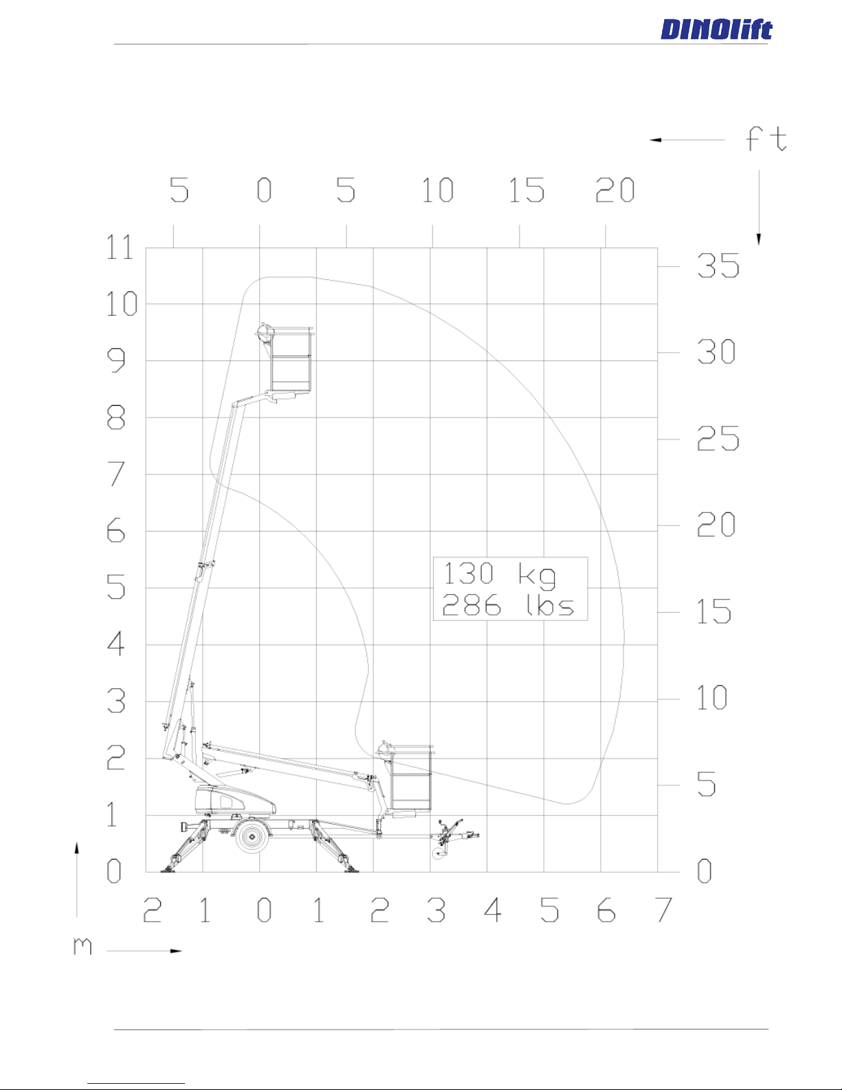
2 REACH DIAGRAM
DINO 105TL
9
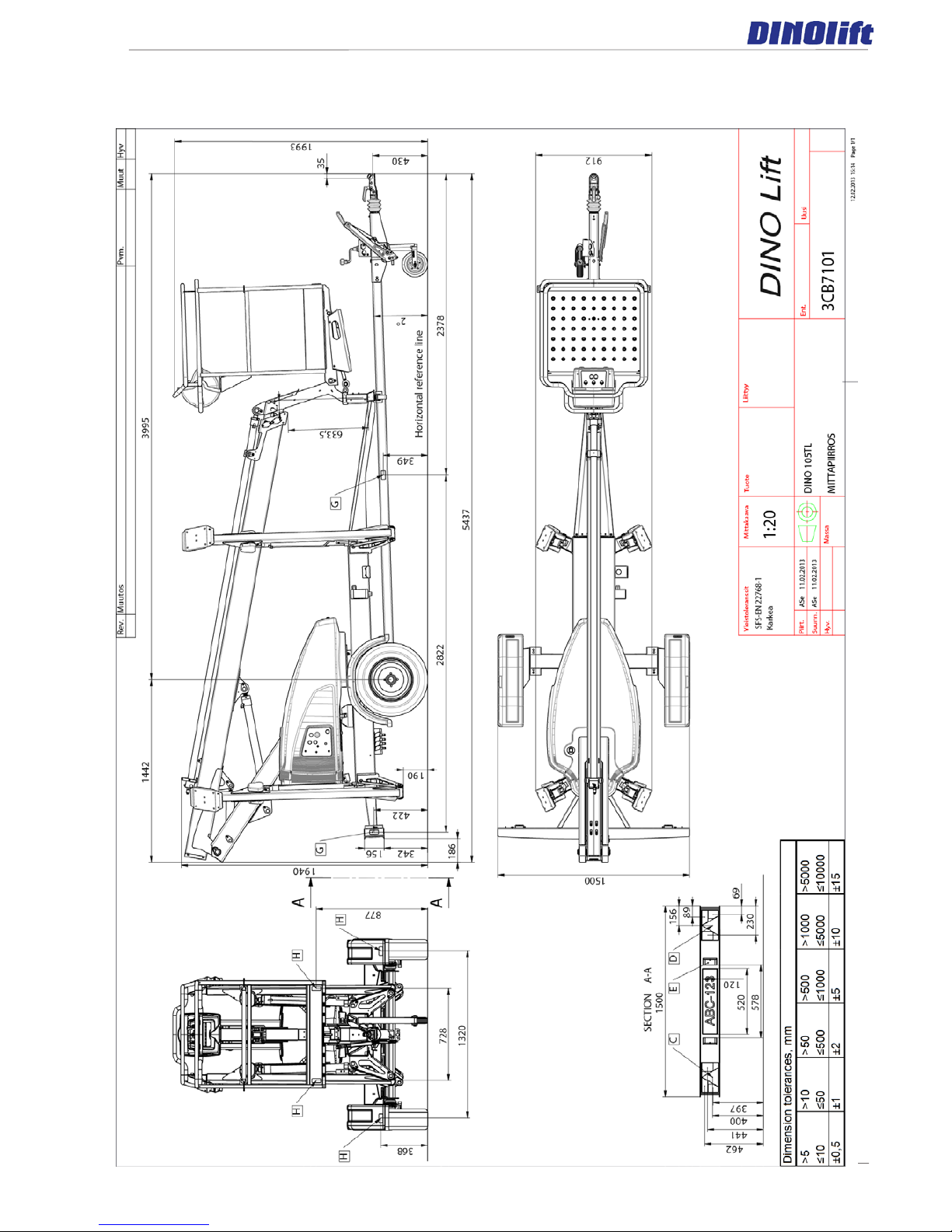
3 DIMENSION DRAWING
DINO 105TL
10
4 TECHNICAL SPECIFICATION
Max. working height 10.5 m
Max. platform height 8.5 m
Max. outreach 6.5 m
Boom rotation +/- 355°
Turn area refer to the reach
diagram
Support width 3.57 m
Transport width 1.5 m
Transport length 5.44 m
Transport height 1.99 m
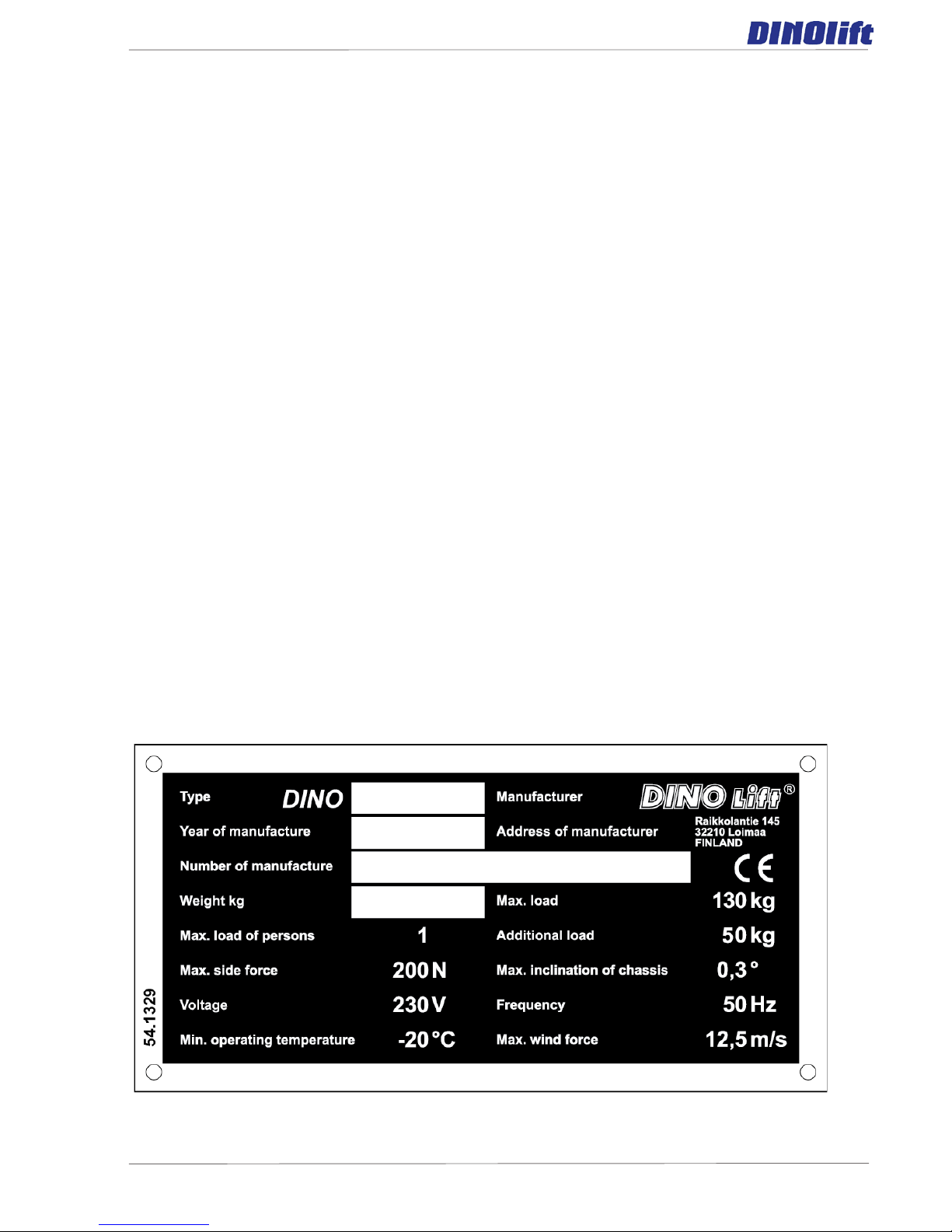
Weight 950 kg
Max. allowed load on platform 130 kg
Max. number of persons + additional load 1 person + 50 kg
Max. allowed sideways load (caused by persons) 200 N
Max. lateral inclination (chassis) ±0,3°
Max. wind speed during operation 12,5 m/s
Min. ambient temperature when working -20 °C
Max. support force on the outriggers 7500 N
Platform size 0.85 m x 0.7 m
Gradeability using the driving device (optional) 15 %
Power supply: 230V/ 50Hz/ 10A
Sound pressure level Under 70 dB
Socket outlets on the platform 2 x 230V/ 50Hz/ 10A
4.1 Example of the machine’s nameplate
DINO 105TL
11
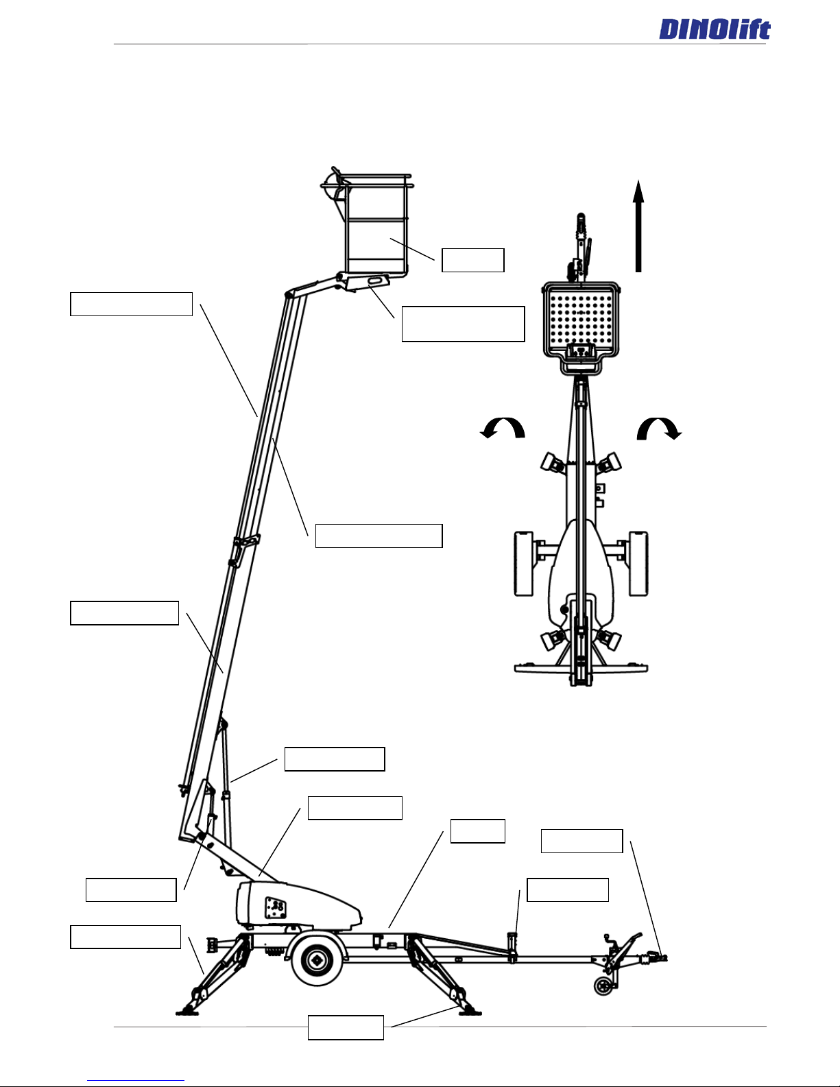
4.2 General description of the machine
The denominations of the machine’s essential parts and concepts, which are used later in
these instructions, are described on this page.
Turning
Counter-clockwise (to the
Platform
drive
Boom extension 1
Boom extension 2
Right
Left
Turning
Clockwise (to the right)
Levelling cylinder of
platform,
Telescope cylinder
Lifting cylinder
Turning device
Outrigger cylinder
Outrigger
Master cylinder
Chassi
Coupling
Boom
DINO 105TL
12
4.3 Description of the machine’s intended use
The Access Platform is exclusively intended for transferring people and tools, as well as for
acting as a work platform to the limit of its load-bearing capacity and reach (refer to the
table of Technical Specifications and Reach Diagram).
The intended use also covers:
- Following all the instructions in the Operating Instructions.
- Performance of the inspections and maintenance operations.
5 GENERAL SAFETY REGULATIONS
Make yourself familiar with these operating instructions before using the lift!
- Keep these operating instructions in the place reserved for them.
- Make sure that all users of the lift are familiar with these instructions.
- Advise new users and strictly follow all instructions given by the manufacturer.
- Make sure you clearly understand all instructions relating to the operational safety of
the lift.
Always use chocks under the wheels when disconnecting the lift from the car.
Only specially trained personnel with authorisation in writing from their employer and who
have good familiarity with the device and are at least 18-years old are allowed to operate
the lift
- The max. allowed load on the platform is one (1) person and at maximum fifty (50) kg of
additional load, however, the total load must not exceed one hundred thirty (130) kg.
- The platform may only be operated when the chassis is well supported and the wheels
are off the ground.
- The load-bearing capacity and the gradient of the ground must be taken into account
when supporting the chassis.
- Additional support plates of adequate size must be used under the outriggers when
working on soft ground. Only use such additional support plates on which the metallic
outriggers will not slide.
The lift may only be moved in the transport position. No persons or load are allowed on the
platform during the transportation.
The weather conditions, such as wind, visibility and rain, must always be taken into account
so that these factors will not adversely affect the safe performance of the lifting operations.
The lift must not be used if the temperature drops below -20°C or
the wind speed exceeds 12.5 m/s
DINO 105TL
13
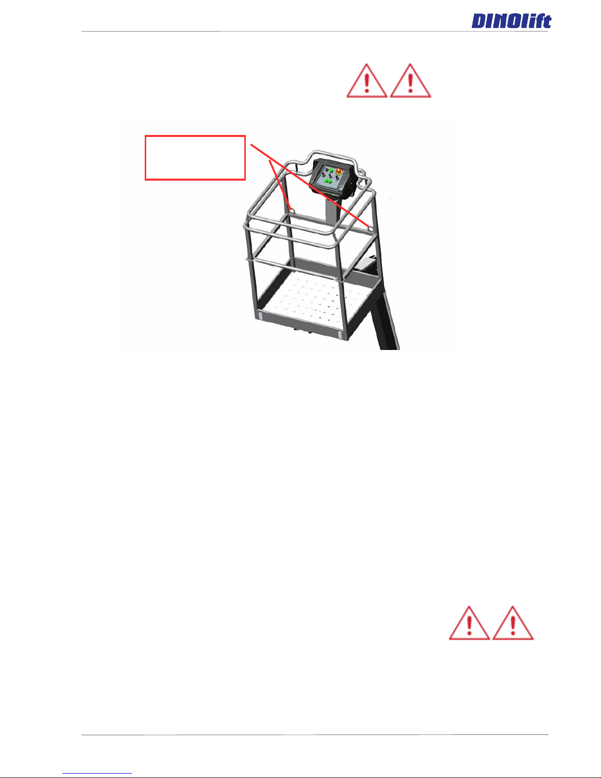
Connecting
points for the
safety harness.
USE THE SAFETY HARNESS!
Do not use ladders, steps or other similar equipment on the platform.
Never throw any objects from the platform.
The lift must not be used for transferring goods or persons between different floors or
working levels.
Always make sure before lowering the platform that the area on the underside is clear of
any obstructions.
Avoid damaging the platform by lowering it on the ground or bringing it in contact with any
structures.
When working in busy areas the operating range of the lift must be clearly marked by using
either warning lights or fencing.
Also observe the regulations of the Road Traffic Act.
Beware of the live aerial power lines in the area – observe the
minimum safety distances:
Keep the lift free of any dirt which may impair safe operation and impede the inspection of
the structures.
The device must be serviced and inspected regularly.
DINO 105TL
14
Only skilled persons familiar with servicing and repair instructions are allowed to carry out
servicing and repair work.
It is strictly prohibited to use a lift which is out of order.
The operator must be given instructions and cons e nt f rom the
manufacturer for all such specific wor k met hods or
conditions that the m a nuf a c t urer has not explicitly defined.
The device must neither be altered without the manufacturer’s
consent nor be used under conditions which do not meet the
requirements set by the manufacturer.
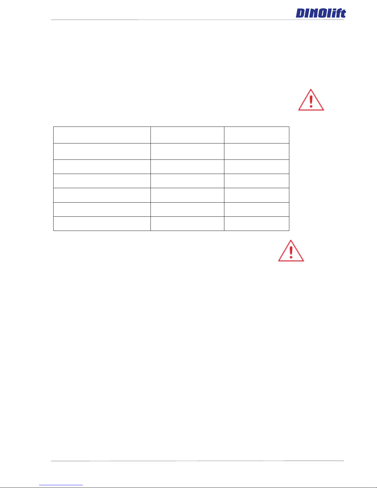
5.1
Voltage
Min. distance below
(m)
Min. distance at
the side (m)
100 – 400 V hanging spiral
cable
0.5 0.5
100 – 400 V open-wire cable 2 2
6 – 45 kV 2 3
110 kV 3 5
220 kV 4 5
400 kV 5 5
DINO 105TL
15
5.1 Instructions for s afe operation!
- Use a safety harness while on the platform.
- Never load the platform while in the upper position.
- The lift must not be used when the temperature is below -20°C and the wind
speed exceeds 12.5 m/s.
- Beware of live power lines within the work area.
- The lift MUST NOT be used as a crane.
- Always ensure the load-bearing capacity of the ground.
- Ensure the unobstructed range of movement before operating the outriggers.
- While in the support position, ensure that the wheels are off the ground.
- Always verify the horizontal position of the machine.
- Ensure that the outriggers cannot slide while on a gradient.
- Always ensure that the work area is clear of outsiders. Danger of getting
squeezed between rotating and fixed structures.
- Stepping on or off the platform in motion is prohibited.
- The maximum-allowed gradient duri ng transfers is 5°. During transfer in rough
terrain, try to stay above the machine.
- While operating the boom from the control panel on the turning device, beware of
getting pressed against the outriggers or other structures that do not turn with the
boom.
- When the boom is in its lowest positi ons, make sure it cannot clash duri ng
rotation with structures that do not turn with the boom.
- Before operating, always ensure that the safety devices and the emergency
descent system are in working order.
- Do not take tools/material of large surface area onto the platform. The increase in
wind load may jeopardize the stability of the device.
- Always keep the lift free from dirt, snow and ice.
- Ensure that the lift is inspected and serviced, before use.
- Never use a defective lift.

DINO 105TL
16
- Never use a lift alone. Make sure that there is always someone on the ground,
who can call for help in case of an emergency.
6 INSPECTIONS
The lift must be subjected to a start-up inspection before it is used for the first time and
before starting it up the first time after a major repair or modification work.
The lift must be subjected to a thorough periodic inspection with related test drive at
intervals of year.
The lift must be subjected to a thorough periodic inspection with test drive at intervals of
four years.
In connection with the periodic inspection the lift must be subjected to a non-destructive
inspection/inspection disassembled in general at intervals of ten (10) years from the
start-up date.
In addition, the lift much be inspected to the extent applicable after any exceptional
situation
For the inspection must be assigned an expert inspection body with documented
evidence of competence or an expert with documented evidence of competence.
A protocol must be drawn up of the executed inspections. The protocols of the start-up
and periodic inspections must be kept with the lift or its immediate proximity for at least five
years.
Carry out the inspections regularly basis throughout the service life of the lift.
The inspection must be carried out within twelve (12) months off the first or previous
inspection.
If the lift is used under extreme conditions, intervals between the inspections shall be
reduced.
The overall operating condition of the lift as well as the condition of the safety-related
control devices shall be established in the regular inspections. Particular attention shall be
paid to changes which affect the operational safety.
In connection with the regular inspection, it shall be established to what extent the lessons
and practical experience gained from the previous inspection can be implemented for even
better safety.
Regular inspections and service measures are described more thoroughly in the chapter
“Service- and maintenance”.

DINO 105TL
17
7 WORKSITE INSPECTION
1. General information
- Is the lift suited for the intended job?
- Is the performance of the lift sufficient for the job? (reach, loadability etc.)
- Is the position of the lift safe?
- Is the lighting on the worksite sufficient?
2. Documents
- Are the Operation and Service Instructions for this lift present? (Manufacturer´s
instructions)
- Are inspections and servicing carried out in accordance with the instructions and
have the defects affecting the safety been checked as repaired?
(Inspection protocols)
3. Structure (Visual inspection and operational test)
- General condition of the lift
- Operation and protection of the controls
- Emergency stop, signal horn and limit switches
- Electrical appliances and wiring
- Oil leaks
- Load markings and signs
4. Operator
- Is the operator old enough?
- Has the operator received the required training?
5. Special issues on the worksite
- Are there any additional regulations relevant to the worksite or the work?
DINO 105TL
18
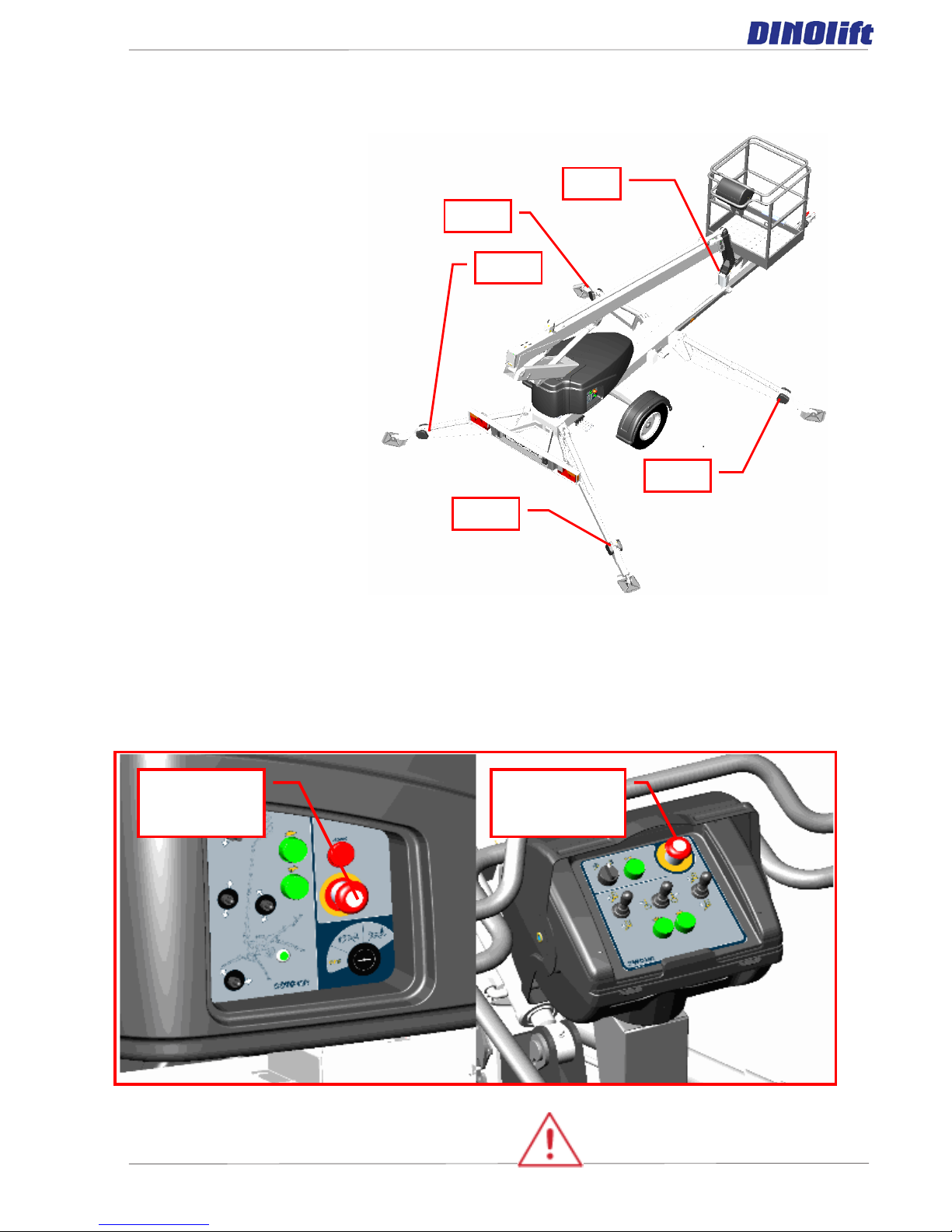
RK3
RK11
RK14
RK13
RK12
8 OPERATION OF THE SAFETY DEVICES
1. Outriggers
The safety limit switch RK3
prevents the operation of
the outriggers and the
driving device when the
boom does not rest on the
transport support. The
switch is located on the towbar at the transport support.
2. Lifting of the boom
All the lift’s support
outriggers must be in the
support position before the
boom is lifted. Make sure
that the wheels are off the
ground. The safety limit
switches RK11, RK12,
RK13 and RK14 are
located on the support
outriggers.
3. As the emergency stop button is depressed all movements stop and the power unit
is turned off. The emergency stop pushbutton must be pulled up before sta r ting the
power unit.
Check operation of the safety devices.
Emergency
stop in the LCB
centre
Emergency stop
in the UCB
centre
DINO 105TL
19
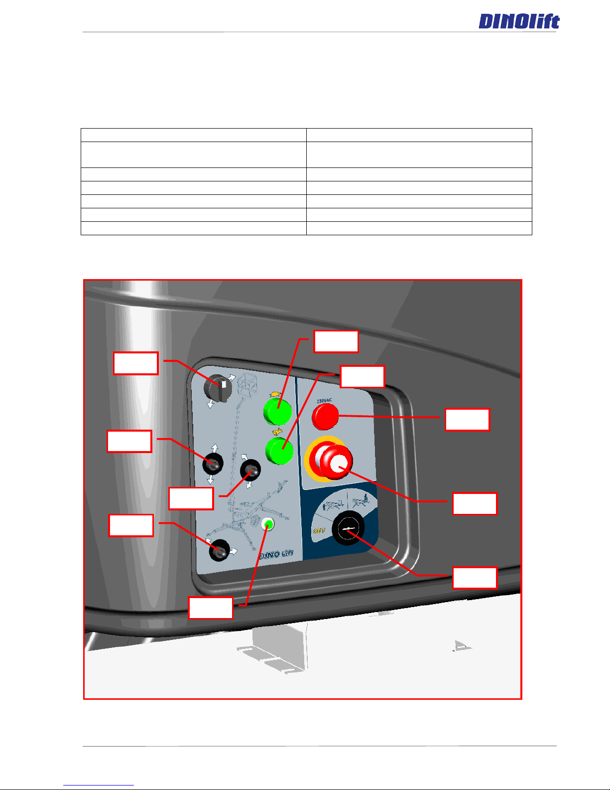
S20
S18
S16
S17
H3
Q1
S1
Vi
S2
S3
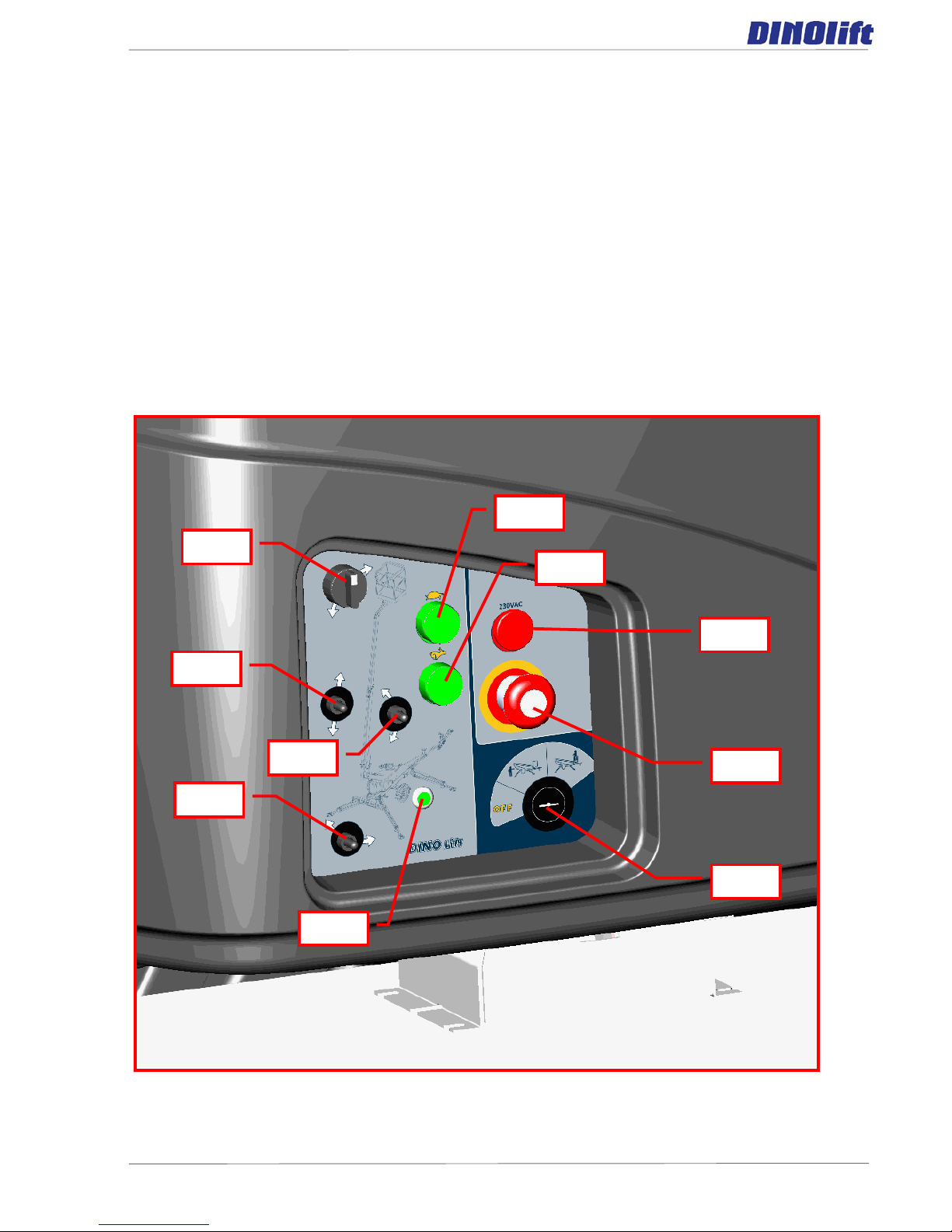
9 OPERATING CONTROLS
9.1 OPERATING CONTROLS IN THE CHASSIS CONTROL CENTRE
Q1.Selector switch
S3. High speed selection/start
Q1.1 OFF – power off
H3.Signal light for the limit switches for
outriggers
Q1.2 LCB control centre – outriggers
S16. Lever for turning the boom system
Q1.3 UCB platform control centre
S17. Lever for lifting the boom system
S1. Emergency stop
S18. Lever for telescope movement
Vi. Power on – signal light
S20. Lever for platform inclination
S2.Low speed selection/start
DINO 105TL
20
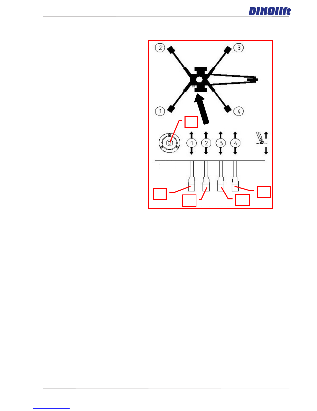
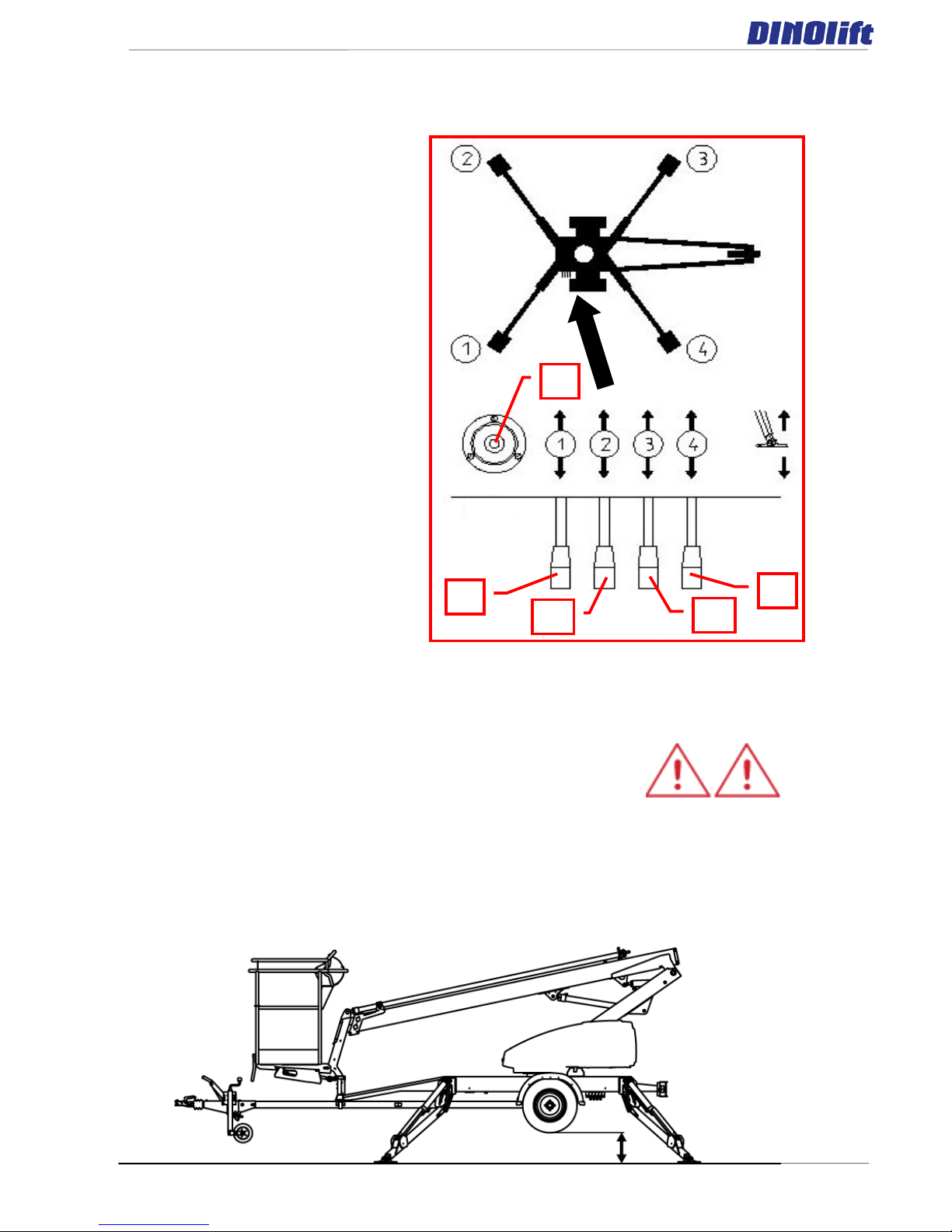
1 2 3 4 5
9.2 OPERATING CONTROLS OF
OUTRIGGERS
1. Rear outrigger, right
2. Rear outrigger, left
3. Front outrigger, left
4. Front outrigger, right
5. Position indicator of chassis
(water level)
DINO 105TL
21
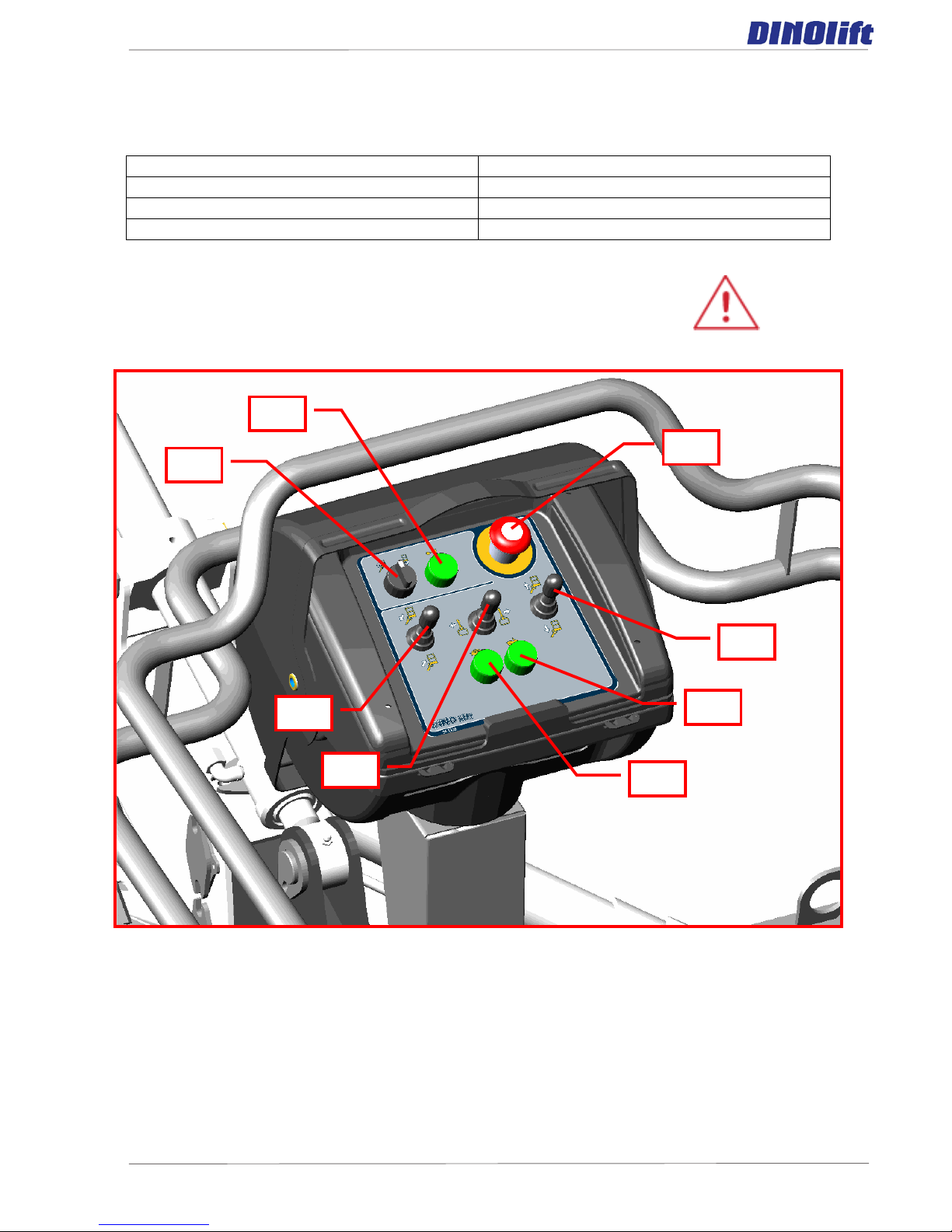
S6
S5
S8
S9
S7
S4
S10
S12
9.3 OPERATING CONTROLS IN THE P LATFORM CONTROL CENTRE UCB
Take away the key from the selector switch Q1 before you start
operating the lift from the platform control centre UCB
S4. Emergency stop
S8. Lever for lifting the boom system
S5.Low speed selection/start
S9. Lever for telescope movement
S6. High speed selection/start
S10.Sound signal
S7. Lever for turning the boom system
S12. Lever for levelling the platform
DINO 105TL
22
10 MEASURES TO BE TAKEN IN THE CASE OF EMERGENCY/IF THE LIFT IS
AT RISK OF LOSING ITS STABILITY
Reduced stability can be caused by a fault in the lift, the wind or other
lateral force, collapse of the standing base or negligence in providing
sufficient support. In most cases one sign of reduced stability is the
inclination of the lift.
WHEN AT RISK OF LOSING THE STABILITY
1. If there is time, try to find out the reason for the reduced stability and the direction of its
effect. Warn other people on the worksite using the alarm signal.
2. If possible, reduce the load from the platform in a safe manner.
3. Reduce the outreach to the side by retracting the telescope. Avoid abrupt movements.
4. Turn the boom away from the danger zone, i.e. to a position where the stability of the lift
is normal.
5. Lower the boom.
If the stability has been lost as a result of a fault in the lift, repair such a fault immediately.
Do not use the lift until the fault has been repair ed and the condition of the lift has
been verified.
IN CASE OF OVERLOADING
1. If there is time, try to find out the reason for the reduced stability and the direction of its
effect. Warn other people on the worksite using the alarm signal.
2. If possible, reduce the load from the platform in a safe manner.
3. Reduce the outreach to the side by retracting the telescope.
IN CASE THE POWER SUPPLY IS INTERRUPTED (electric motor)
1. Lower the boom using the emergency descent system (see point “Emergency descent
system”)
2. Establish the reason why the energy supply was interrupted.
IN CASE OF MALFUNCTION, WHEN EVEN THE EMERGENCY DESCENT SYSTEM IS
NOT OPERATIONAL
1. If the emergency descent system does not operate, try to warn other personnel present
on the site or call for help so that the power supply required for normal operation can be
resumed or the lift can be made operational by some other means so that the person on the
platform can be lowered safely down.
DINO 105TL
23
11 STARTING UP
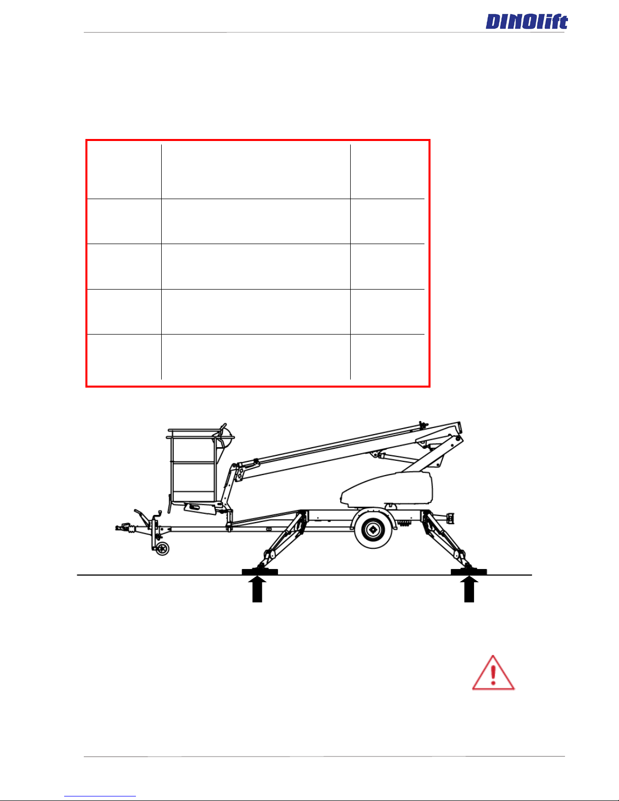
1. Ground stability
- make sure that the ground is even and hard enough to support the lift in a steady level
position.
– if the ground is soft, use sufficiently large and sturdy additional plates under the support
outriggers
– observe the effect of ice, possible rain and inclination of the surface on
the support (the support outriggers must not slip on the surface)
– the operation is prohibited if the lift is not properly supported and in a level position
(<0,3°)
Soil
material
Density
Max.
ground
pressure
P kg/cm²
Gravel
High density
6
Medium density
4
Loose
2
Sand
High density
5
Medium density
3
Loose
1,5
Fine sand
High density
4
Medium density
2
Loose
1
Sand/ mud
High density (very hard to work)
1.00
Medium density (hard to work)
0.50
Loose (easily worked)
0.25
DINO 105TL
24
S20
S18
S16
S17
H3
Q1
S1
Vi
S2
S3
2. Drive the lift to the ins p ected lifting site
- apply the parking brake
- disconnect the lift from the towing vehicle
3. Connection of power supply to the lift
- connect the mains cable to the power supply
- for maximum out of the electric motor the voltage must 230 VAC (-10 % +6 %), the
frequency must be 50 Hz and rating of the fuse 10A (the length of the connecting cable
has some effect)
4. Turn the selector switch (Q1) to position LCB – chassis centre
5. Start the engine from the pushbutton S2 or S3
DINO 105TL
25
1
2
3 4 5
7. Lower the front outriggers 3
and 4 (on the tow-bar side) on the
ground
8. Lower the rear outriggers 1
and 2
9. Level the chassis using the
outriggers in accordance with the
level gauge.
DO NOT LOAD THE TOW-BAR JOCKEY WHEEL
MAKE SURE THAT THE WHEELS ARE CLEARLY OFF THE
GROUND
– the (green) signal light H3 on the chassis control centre LCB comes on when all the
outriggers are in the support position, and the outrigger limit switch circuit is
connected.
– make sure all outriggers are firmly supported on the ground
 Loading...