

Dinolift DINO 105T Operating Instructions Manual
DINO ® 105T
OPERATING INSTRUCTIONS
®
Raikkolantie 145
FI-32210 LOIMAA
T. +358 2 762 5900
F. +358 2 762 7160
dino@dinolift.com
www.dinolift.com

DINO 105T
2

DINO 105T
3
OPERATING INSTRUCTIONS

DINO 105T
4
Valid from serial number 5336

DINO 105T
5
CONTENTS
TECHNICAL SPECIFICATION .........................................................................................................................................7
REACH DIAGRAM...............................................................................................................................................................8
GENERAL SAFETY REGULATIONS ...............................................................................................................................9
REGULAR INSPECTION ..................................................................................................................................................11
WORKSITE INSPECTION ................................................................................................................................................12
OPERATION OF THE SAFETY DEVICES.....................................................................................................................13
ENSURE THE OPERATION OF THE SAFETY DEVICES - DO NOT LOCK THE CHASSIS PANEL (OK1) COVER WITH KEY WHILE THE
LIFT IS IN OPERATION
...........................................................................................................................................................13
OPERATING CONTROLS.................................................................................................................................................14
OPERATING CONTROLS ON CHASSIS PANEL ..........................................................................................................14
CONTROL OF THE OUTRIGGERS AND THE WATER LEVEL...................................................................................15
OPERATING CONTROLS ON THE PLATFORM...........................................................................................................16
MEASURES TO BE TAKEN IF THE LIFT IS AT RISK OF LOSING ITS STABILITY ..........................................17
START-UP ............................................................................................................................................................................18
OPERATING THE LIFT FROM THE CHASSIS PANEL ................................................................................................21
OPERATING THE LIFT FROM THE PLATFORM PANEL............................................................................................22
STARTING AFTER THE SAFETY DEVICES FOR THE PLATFORM LEVELLING HAVE CAUSED STOPPING OF
THE POWER UNIT ...........................................................................................................................................................23
EMERGENCY DESCENT SYSTEM.................................................................................................................................25
SPECIAL INSTRUCTIONS FOR WINTER USE............................................................................................................26
MEASURES TO BE TAKEN AT THE END OF THE WORKING DAY .....................................................................27
PREPARING THE LIFT FOR TRANSPORT..................................................................................................................28
CONNECTION TO THE TOWING VEHICLE...............................................................................................................29
MAKING THE LIFT NARROWER FOR TRANSPORTATION ..................................................................................30
SERVICE AND MAINTENANCE .....................................................................................................................................32
GENERAL SERVICE INSTRUCTIONS...........................................................................................................................32
SERVICE AND INSPECTIONS........................................................................................................................................33
LUBRICATION PLAN......................................................................................................................................................34
LOAD HOLDING AND LOAD REGULATION VALVES..............................................................................................36
WHEEL BRAKES AND BEARINGS ...............................................................................................................................38
ADJUSTMENT OF THE PLATFORM LEVELLING.......................................................................................................39
REGULAR SERVICING ...................................................................................................................................................40
INSPECTION INSTRUCTIONS........................................................................................................................................48
FIRST INSPECTION .........................................................................................................................................................48
DAILY INSPECTION (START-UP INSPECTION) .........................................................................................................49
MONTHLY INSPECTION (MAINTENANCE INSPECTION) .......................................................................................50
ANNUAL INSPECTION (REGULAR INSPECTION).....................................................................................................51
EXTRAORDINARY INSPECTION..................................................................................................................................54
TEST LOADING INSTRUCTION FOR REGULAR INSPECTION .....................................................................................................55
FAULT FINDING ................................................................................................................................................................56
GENERAL INFORMATION OF HYDRAULICS ...........................................................................................................61
OPERATION OF THE ELECTRIC COMPONENTS 3556Æ........................................................................................62
MAIN CONTROL CENTRE (LCB), RELAYS .................................................................................................................62

DINO 105T
6
MAIN
CONTROL CENTRE (LCB), OTHER ITEMS.......................................................................................................63
MAIN CONTROL CENTRE (LCB), SWITCHES.............................................................................................................63
CONTROL CENTRE (UCB), RELAYS ............................................................................................................................64
CONTROL CENTRE (UCB), SWITCHES........................................................................................................................64
CONTROL CENTRE (OCB), CONTROL OF OUTRIGGERS.........................................................................................64
CONTROL CENTRE (PLCB) QUICKSILVER SWITCHES FOR LEVELLING OF THE PLATFORM........................64
VALVES, CHASSIS ..........................................................................................................................................................65
VALVES, TURNING DEVICE .........................................................................................................................................65
LIMIT SWITCHES ............................................................................................................................................................66
OTHER MARKINGS.........................................................................................................................................................66
ELECTRIC COMPONENTS 5336 →................................................................................................................................67
ELECTRIC DIAGRAM 5336 Æ ........................................................................................................................................69
HYDRAULIC COMPONENTS..........................................................................................................................................76
HYDRAULIC DIAGRAM...................................................................................................................................................77

DINO 105T
7
TECHNICAL SPECIFICATION
Max. working height 10.5 m
Max. platform height 8.5 m
Max. outreach to the side 6.0 m
Boom rotation continuous
Support width 3.20 m
Transport width, max 1.48 m
Transport width, min 0.78 m
Transport length 5.57 m
Transport height 1.80 m
Total weight 1,010 kg
- axle load 940 kg
- towbar load 70 kg
Max. allowed load on platform 120 kg
Max. number of persons + additional load 1 person +40 kg
Max. allowed sideways load (caused by persons) 200 N
Max. lateral inclination of chassis ±0,3°
Max. wind speed during operation 12,5 m/s
Min. ambient temperature during operation -20 °C
Max. support force on outriggers 7000 N
Platform size 0.7 x 0.7 m
Driving power, AC-current 230V / 50Hz / 10A
External power outlets: Socket outlet on platform (2 pcs.) 230V / 50Hz / 16A
DINO 105T
8
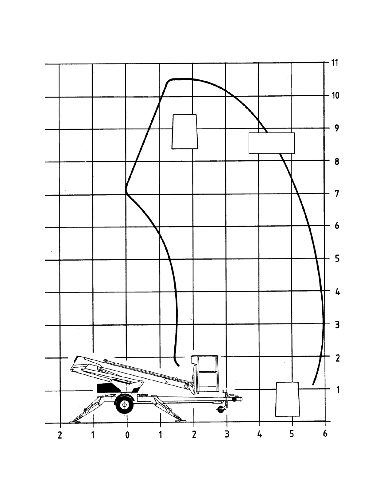
REACH DIAGRAM
120 kg

DINO 105T
9
GENERAL SAFETY REGULATIONS
Make yourself familiar with these operating instructions before using the lift!
Keep these Operating Instructions in the place reserved for them.
Make sure that all users of the lift are familiar with these instructions.
Advice the new users and strictly follow all instructions given by the manufacturer.
Make sure you clearly understand all instructions relating to the operational safety of the lift.
Always use chocks under the wheels when disconnecting the lift from the car.
Only specially trained personnel who are well familiar with the device and at least 18-years old
are allowed to operate the lift
The max. allowed load on the platform is one (1) person and at maximum forty (40) kg of additional
load, however, the total load must not exceed one hundred twenty (120) kg.
The platform may only be operated when the chassis is well supported and the wheels are off the
ground.
The loadbearing capacity and the gradient of the base must be taken into account when supporting the
chassis.
Additional support plates of adequate size must be used under the outriggers when working on soft
ground. Only use such additional support plates on which the metallic outriggers will not slide.
The lift may only be moved in the transport position. No persons or load are allowed on the platform
during the transportation.
The weather conditions, such as wind, visibility and rain, must always be taken into account so that
these factors will not adversely affect the safe performance of the lifting operations.
The use of the lift is prohibited if
- the temperature drops under - 20 °C or
- the wind speed exceeds 12,5 m/s

DINO 105T
10
Do not use ladders, steps or other similar equipment on the platform.
Never throw any objects from the platform.
The lift must not be used for transferring goods or persons between different floors or working levels.
Never disable the operation of any safety device.
Always make sure before lowering the platform that the area on the underside is clear of any
obstructions.
Avoid damaging the platform by lowering it on the ground or bringing it in contact with any
structures.
When working in busy areas the operating range of the lift must be clearly marked either by using
warning lights or fencing.
Also observe the regulations of the Road Traffic Act.
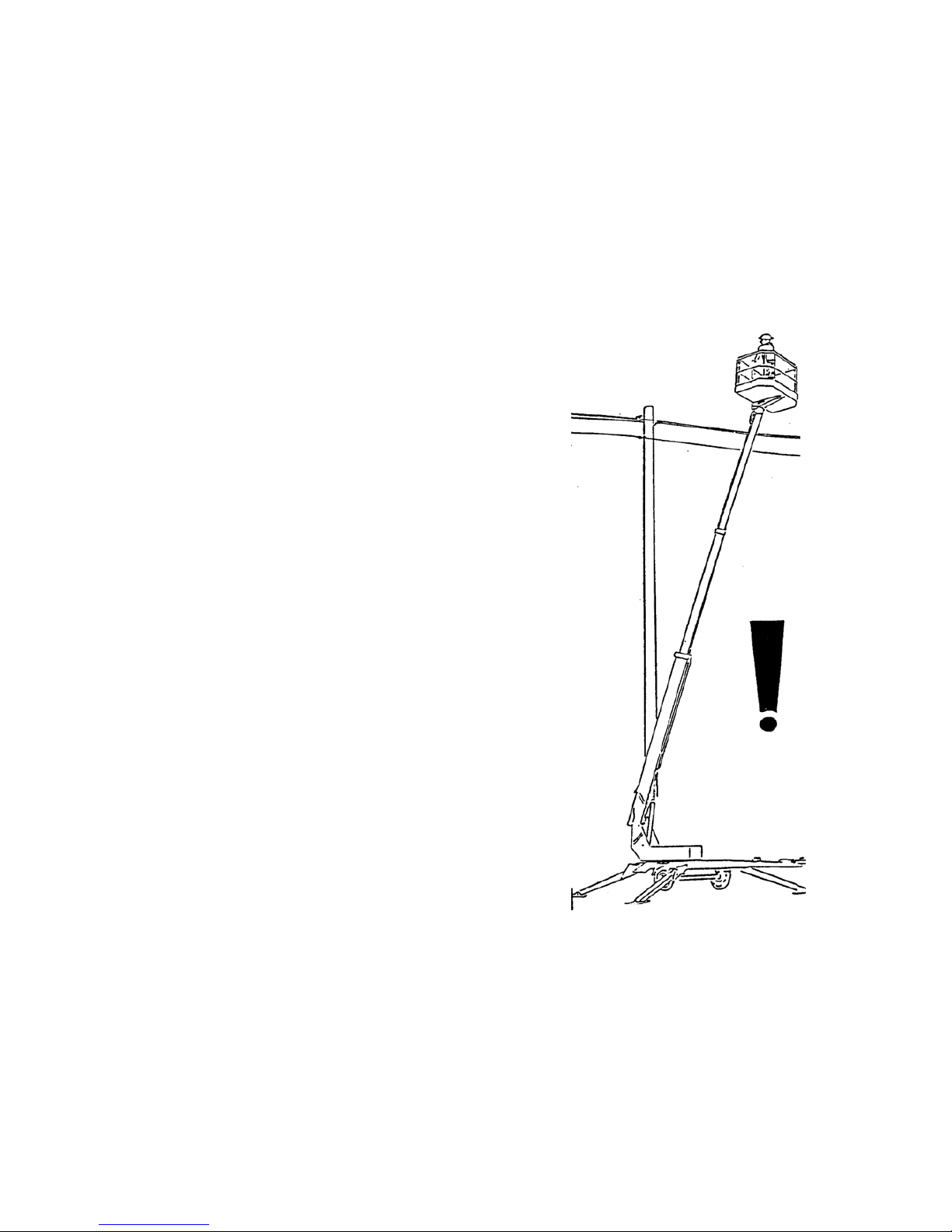
Beware of the live aerial power lines in the area - observe the minimum safety distances:
Keep the lift clean of any dirt which may impair the safe operation and impede the inspection of the
structures
The device must be serviced and inspected regularly.
Only skilled persons who are familiar with the service and reparation instructions are allowed to carry
out the service and reparation work.
It is strictly prohibited to use a lift which is out of order.
The device must not be modified without the manufacturer´s consent.
Voltage Min. distance on the
underside (m)
Min. distance to the
side (m)
100 – 400 V hanging spiral cable 0.5 0.5
100 – 400 V open-wire cable 2 2
6 – 45 kV 2 3
110 kV 3 5
220 kV 4 5
400 kV 5 5

DINO 105T
11
REGULAR INSPECTION
A thorough inspection of the lift must be carried out at least once every twelve (12) months.
The inspection should only be carried out by a person who is technically trained and familiar with the
function, use and construction of the lift.
Inspections should be recorded in a protocol that shall always remain with the unit and be stored in the
space reserved for it.
Inspections must be carried out on regular basis throughout the service life of the lift.
Each inspection must be made within twelve (12) months of the first or previous inspection.
If the lift is operated under especially severe conditions, the inspection intervals should be shorter than
mentioned above.
The general operating condition of the lift and the due operation of the safety and control devices shall
be verified during the regular inspection. Special attention shall be paid to the factors that affect
operational safety.
It should also be established if the findings during the previous inspection or the experience gained
during the operation of the lift give grounds for further improvements in operational safety procedures.
ATTENTION! The regulations laid down by national legislation apply first and foremost!
Regular inspections and service measures are described more thoroughly in the chapter "Service and
Maintenance".

DINO 105T
12
WORKSITE INSPECTION
1. General
- Is the lift suited for the intended job?
- Is the performance of the lift sufficient for the job? (reach, loadability etc.)
- Is the position of the lift safe?
- Is the lighting on the worksiite sufficient?
2. Documents
- Are the Operation and Service Instructions for this lift present? (Manufacturer´s instructions)
- Are inspections and servicing carried out in accordance with the instructions and have the
defects affecting the safety been checked as repaired?
(Inspection protocol)
3. Structure (Visual inspection and operational test)
- General condition of the lift
- Operation and protection of the controls
- Emergency stop, signal horn and limit switches
- Electrical appliances and wiring
- Oil leaks
- Load markings and signs
4. Operator
- Is the operator old enough?
- Has the operator received the required training?
5. Special issues on the work site
- Are there any additional regulations relevant to the worksite or the work?
DINO 105T
13
OPERATION OF THE SAFETY DEVICES
1. Limit switch on the boom support RK3
The safety limit switch prevents the operation of the outriggers if the boom does not rest on the
transport support. The switch is located on the parking support of the towbar.
2. Limit switches for outriggers RK4 - RK7
The safety limit switches prevent the manoeuvring of the boom if the outriggers are not in the
support position. The switches are located on the outriggers.
3. Limit switches for outriggers RK11 - RK14
The safety limit switches prevent the manoeuvring of the boom unless the outriggers are not steady
supported on the ground. The switches are located on the outriggers, one at each outrigger.
4. Emergency stop button
Stops immediately all movements and shuts off the power unit. The emergency stop pushbutton
must be pulled up before the power unit can be restarted (buttons 3).
Ensure the operation of the safety devices - do not lock the chassis panel (OK1) cover with
key while the lift is in operation.
RK4-RK7 RK11-RK14 RK3
3
3
DINO 105T
14
OPERATING CONTROLS
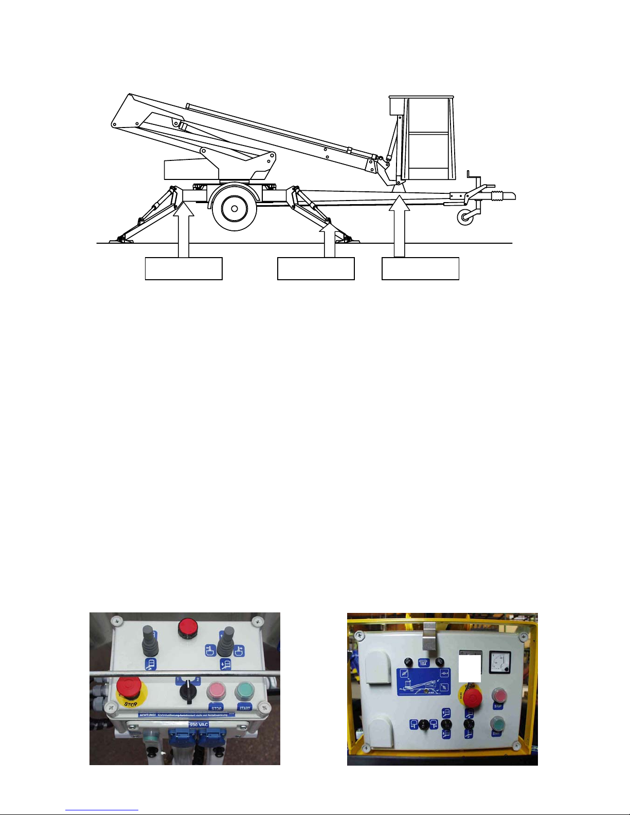
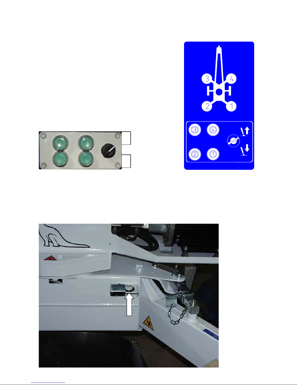
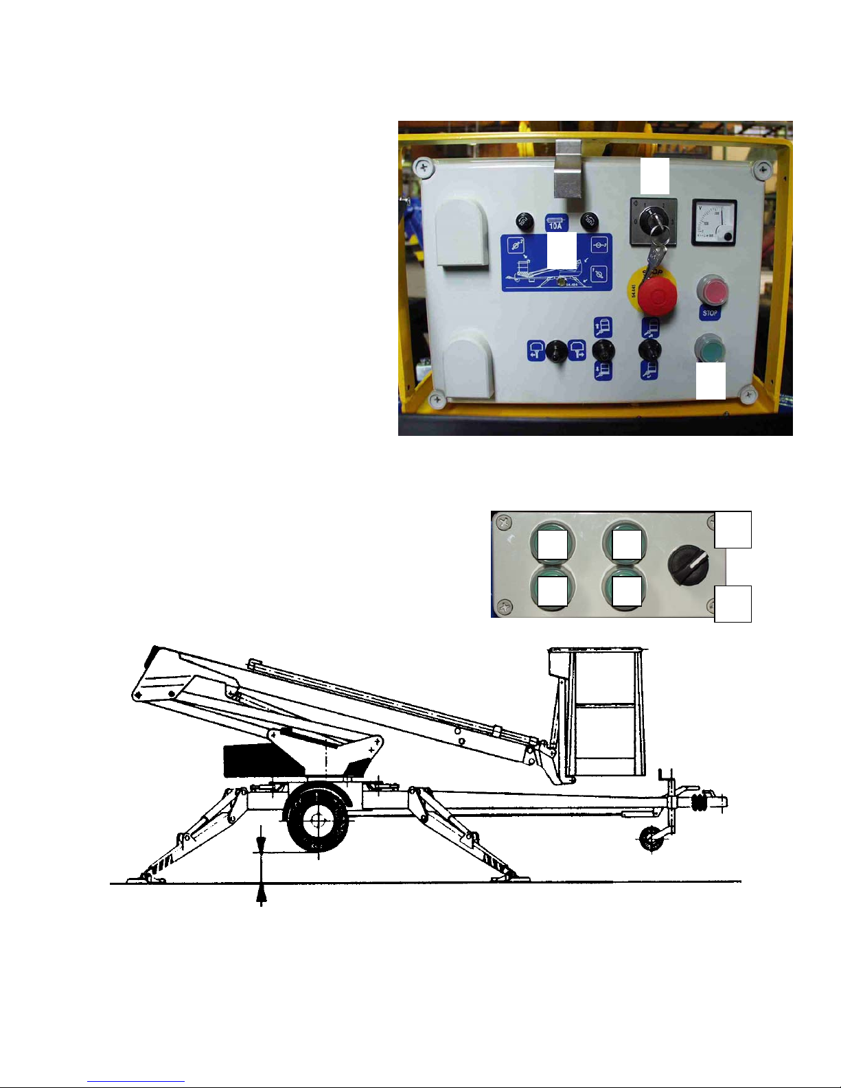
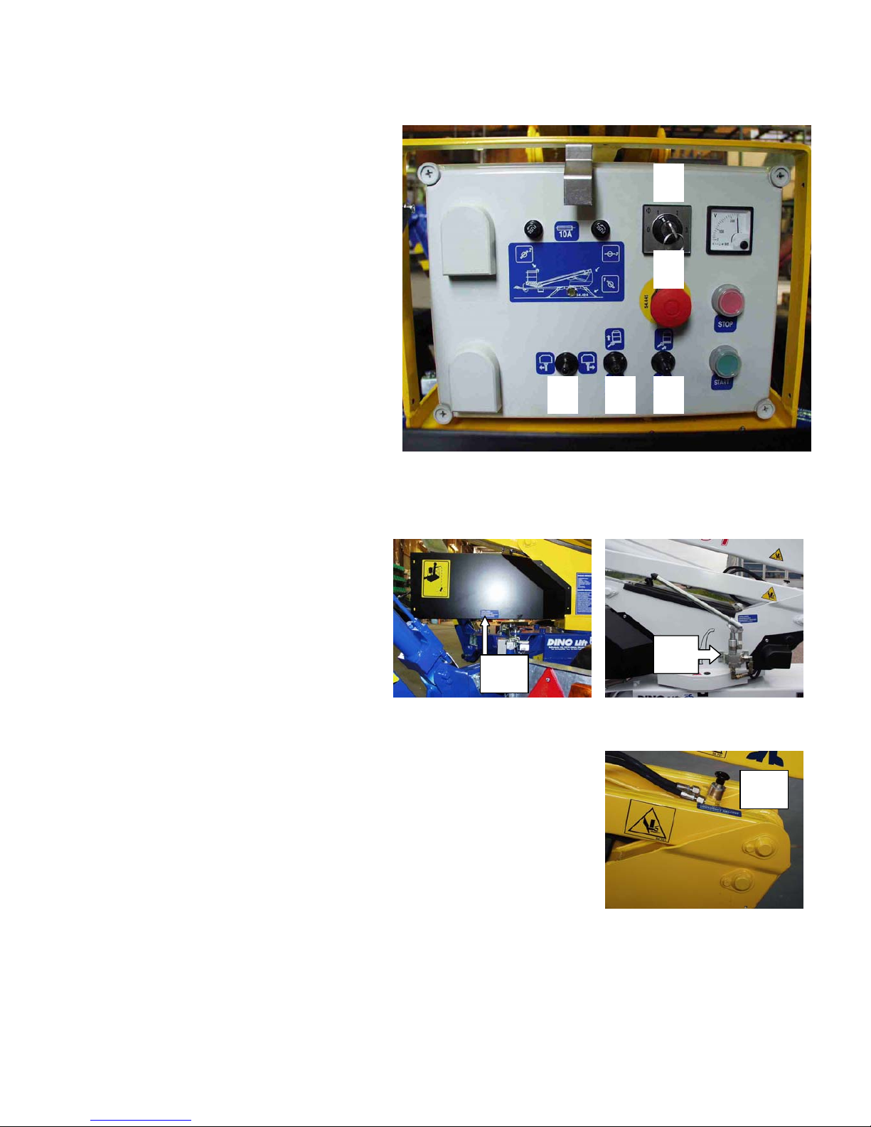
OPERATING CONTROLS ON CHASSIS PANEL
1. Selector switch
0 - ignition off
1 -outrigger circuit
2 -controlling the boom from the
platform
3 -controlling the boom from the
chassis
2. Start button
3. Emergency stop button
4. Signal light for limit switches on the
axle
5. Control lever for turning
6. Control lever for boom system
7. Control lever for telescope
8. Voltage meter
9. Fuse, control levers
10. Fuse, start circuit
11. Stop button
12. Emergency descent valve
12
5 6 7 2
9 10
81
4
113
DINO 105T
15
CONTROL OF THE OUTRIGGERS AND THE WATER LEVEL
1. Rear outrigger, right.
2. Rear outrigger, left
3. Front outrigger, left
4. Front outrigger, right.
A = Raising of the outrigger
B = Lowering of the outrigger
Level the chassis with the outriggers with the help of the level position indicator (Water level).
B
A
DINO 105T
16
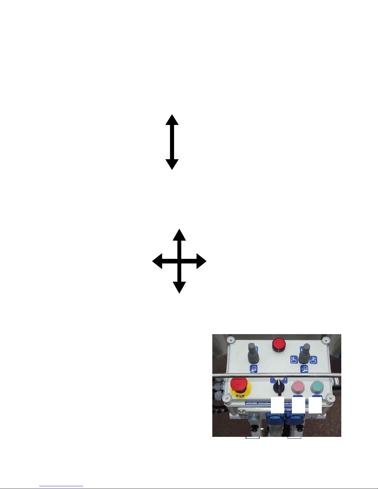
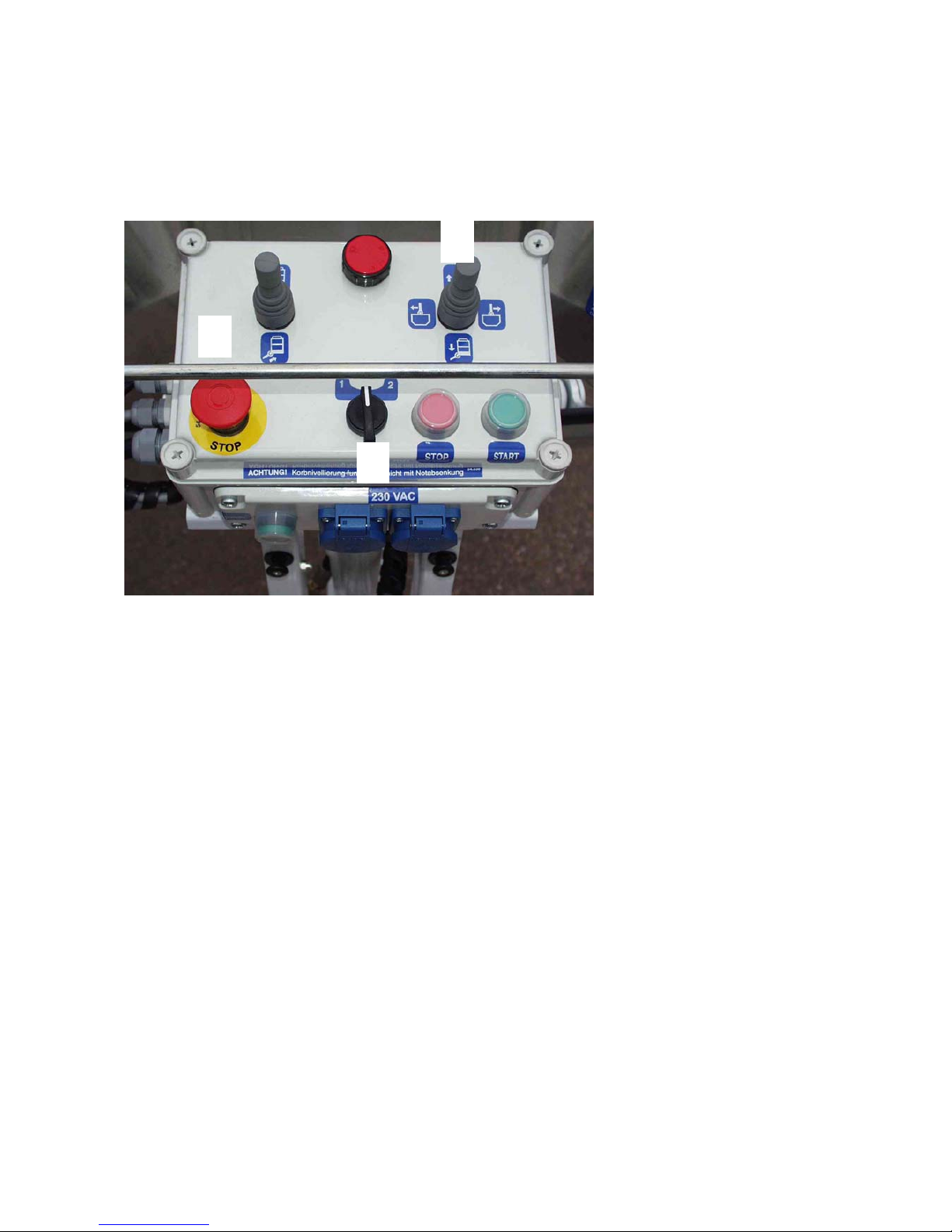
OPERATING CONTROLS ON THE PLATFORM
Lock the operating switch in position 2 (controlling the boom with the platform panel) Close the
chassis control panel cover before operating the controls on the platform. The cover must not be
locked while the lift is in operation.
1. Control lever
2. Control lever
3. Emergency stop
- push to stop
- pull to reset
4. Sound signal
5. Socket outlet 230VAC/ (2 pcs.)
6. Stopping the engine
7. Starting the engine
8. I/II speed (is used simultaneously with control
levers of the boom)
BOOM TO THE RIGHT
BOOM TO THE LEFT
BOOM UP
BOOM DOWN
5
21
4
3
TELSCOPE IN
TELESCOPE OUT
6 78

DINO 105T
17
MEASURES TO BE TAKEN IF THE LIFT IS AT RISK OF LOSING ITS
STABILITY
The reason for the reduced stability can be a fault in the lift, the wind or other lateral force, collapse of
the standing base or negligence in providing sufficient support. In most cases a sign of the reduced
stability is the inclination of the lift.
1. If there is time, try to find out the reason for the reduced stability and the direction of its effect.
Warn other people on the work site using the alarm signal.
2. Reduce the outreach to the side by retracting the telescope. Avoid abrupt movements.
3. Turn the boom away from the danger zone, i.e. to a position where the stability of the lift is
normal.
4. Lower the boom.
If the stability has been lost as a result of a fault in the lift, repair such a fault immediately.
Do not use the lift until the fault has been repaired and the condition of the lift has been verified.
DINO 105T
18
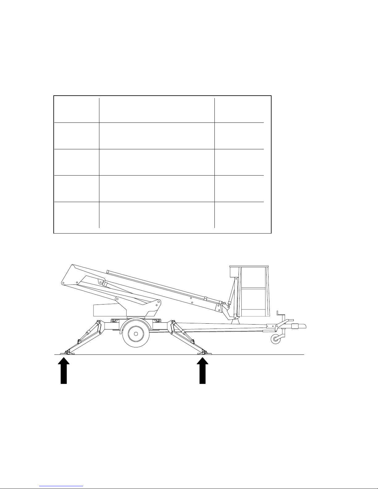
START-UP
1. Ground stability
- make sure that the ground is even and hard enough to support the lift in a steady level position (see
table).
- if the ground is soft, use sufficiently large and sturdy additional plates under the support outriggers
- observe the effect of ice, possible rain and inclination of the surface on the support.
(the support outriggers must not slip on the surface)
- the operation is prohibited if the lift is not properly supported and in a level position
Ground
material
Density Max. ground
pressure
P kg/cm²
Gravel High density 6
Medium density 4
Loose 2
Sand High density 5
Medium density 3
Loose 1,5
Fine sand High density 4
Medium density 2
Loose 1
Sand/ mud High density (very hard to work) 1,00
Medium density (hard to work) 0,50
Loose (easily worked) 0,25
DINO 105T
19
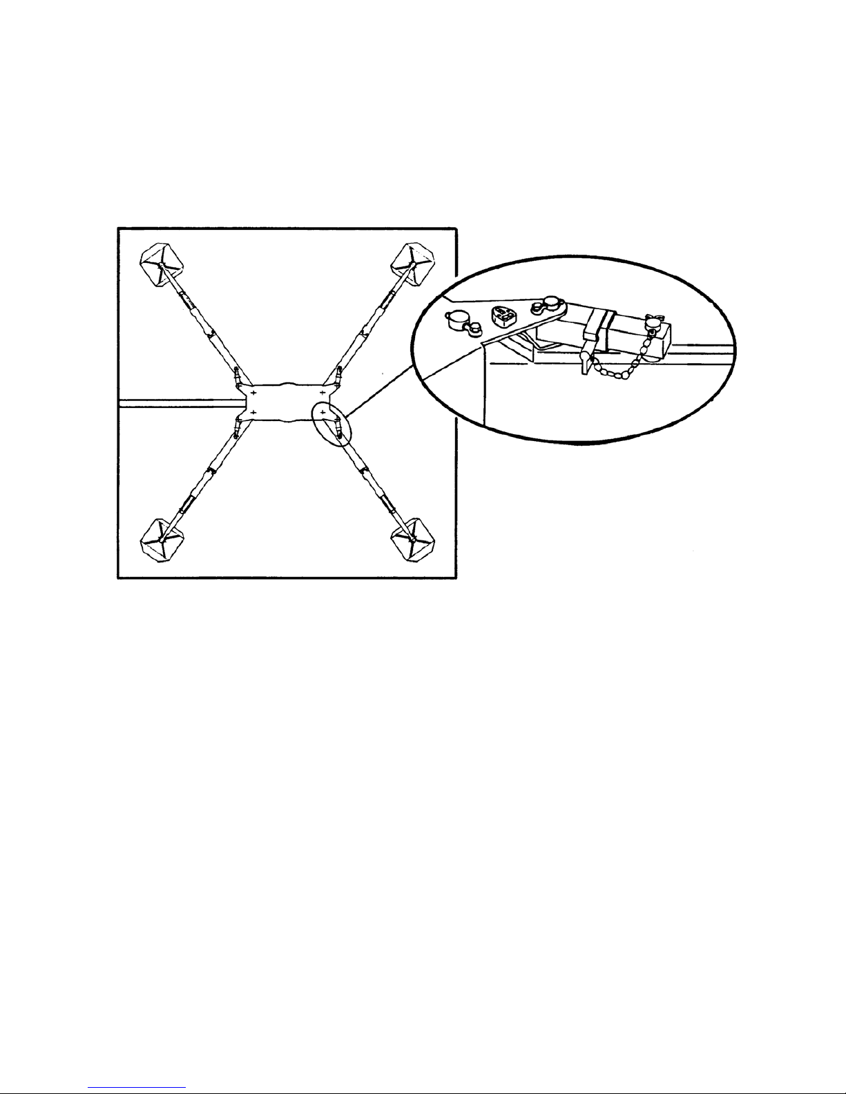
2. Drive or push the lift to the inspected lifting site
- apply the parking brake
- disconnect the lift from the towing vehicle
3. Turn and lower the outriggers to support position
4. Connection of power supply to the lift
- connect the mains cable to the power supply
- for maximum out of the electric motor the voltage must 230 VAC (-10%/ +6%), the frequency
must be 50 Hz and rating of the fuse 10A (the length of the connecting cable has some effect)
DINO 105T
20
5. To access the operating controls open the cover on the chassis.
6. Turn the selector switch (1) to
position 1
7. Start the engine with button 2 (green).
8. Lower the front support outriggers (3
and 4, on the towbar side)
9. Lower the rear support outriggers (1
and 2, do not damage the towbar
jockey wheel)
10. Level the chassis with the outriggers
with the help of the level indicator.
- the signal light 4 in the main centre is lit while the
limit switches on the outriggers are closed
- make sure all outriggers are firmly supported on the
ground
Make sure that the wheels are off the ground.
A
B
2
1
4
DINO 105T
21
OPERATING THE LIFT FROM THE CHASSIS PANEL
11. Turn the operating switch (1) to
position 3
- now you can operate the boom with
levers 5-7 on the chassis control
panel.
- test the operation of the emergency
descent system as follows:
- extend the telescope (switch 7)
- lift the boom about 1 - 2 metres
(with switch 6) and at the same time
push down the emergency stop
button (3) - the movement should
stop.
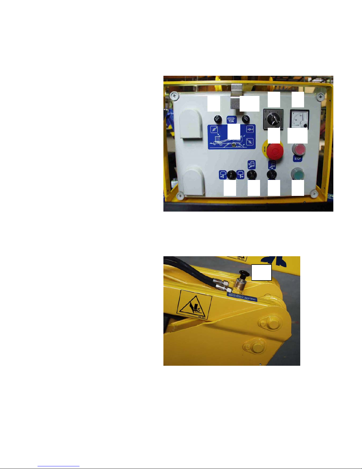
- Open the emergency descent valve 13 for the telescope and retract the telescope completely
using the hand pump 14 (the handle is inside the main centre cover)
- Close the emergency descent valve
for the telescope
- Push down the emergency descent
valve 12 until the boom starts lowering
BE CAREFUL OF THE BOOM!
- pull up the emergency stop button.
Note!
The platform levelling does not operate while the emergency descent
system is in use.
Carefully push down the emergency descent valve 12 and observe the
platform during the lowering.
DO NOT DAMAGE THE HAND BRAKE AND THE TOWBAR JOCKEY WHEEL!
From the chassis control panel the boom can only be operated at the 1-speed.
Lock the selector switch (1) in position 1 (support outriggers) before working under the boom
Make sure that neither people nor load are on the platform.
13
5 6 7
1
3
14
12
DINO 105T
22
OPERATING THE LIFT FROM THE PLATFORM PANEL
12. Turn the operating switch (1) to position 2 and lock it.
Do not lock the chassis control panel cover with key.
The platform can be operated at two different speeds from the platform control panel.
Turn the switch 8 and at the same time move the contol levers 1 and 2 on the platform control
panel in the desired movement direction.
- to the left ( 1-speed)
- to the right ( 2-speed)
Only use the 2-speed at low elevations with short boom.
If possible, keep the boom retracted during raising and lowering.
DO NOT DAMAGE THE HAND BRAKE AND THE TOWBAR JOCKEY WHEEL!
5
6 7
1
4
2
8
3

DINO 105T
23
STARTING AFTER THE SAFETY DEVICES FOR THE PLATFORM LEVELLING HAVE
CAUSED STOPPING OF THE POWER UNIT
Before starting find out the reason why the safety devices have operated
- push the start button on the chassis or on the platform control panel and at the same time raise
the boom as much as is necessary to leave the power unit running
- lower the boom.
- shut the power unit
The lift is now ready for operation.
With the boom slightly lifted and the telescope slightly extended, make sure that the platform does not
lower of itself while the operating controls are not being used.
Under cold conditions let the engine run for a while without load to raise the temperature of the
hydraulic oil. Carefully start the operation by driving the movements slowly back and forth from the
lower control panel without any load on the platform.
Move the platform to the work object
Note!
When bringing the platform to transport position always retract first the telescope completely and then
place the platform to the centre of the towbar. Lower the boom and extend the telescope to lock it in
the transport support.
DO NOT DAMAGE THE HAND BRAKE AND THE TOWBAR JOCKEY WHEEL!
DINO 105T
24
Working a long time in the same position
- there are pushbuttons for both stopping and starting on both the upper and the lower control
panels. When the weather is warm and the platform is kept for a longer period in the same
position, it is not necessary to let the engine run continuously.
- when the weather is cold, it is recommended to let the engine run to keep the hydraulic oil
warm.
- check the stability and condition of the base regularly during the operation, taking into account
the weather and ground conditions.
When moving the platform, remember the following
- be careful of the high voltage power lines
- do not exceed the max. allowed lateral force (200N)
- do not touch open electric wires
- do not throw objects from the platform
- do not damage the lift
- do not take additional load in the upper position
- do not damage other devices
- do not load the platform vertically more than what is
allowed
When leaving the lift
- drive the lift to a safe position, preferably to the
transport position
- switch off the power unit
- prevent unauthorized use of the lift by locking the
control centre cover.
 Loading...