

Dinolift 135TB, 150TB, 180TB Quick Manual
QUICK GUIDE
135TB - 150TB - 180TB
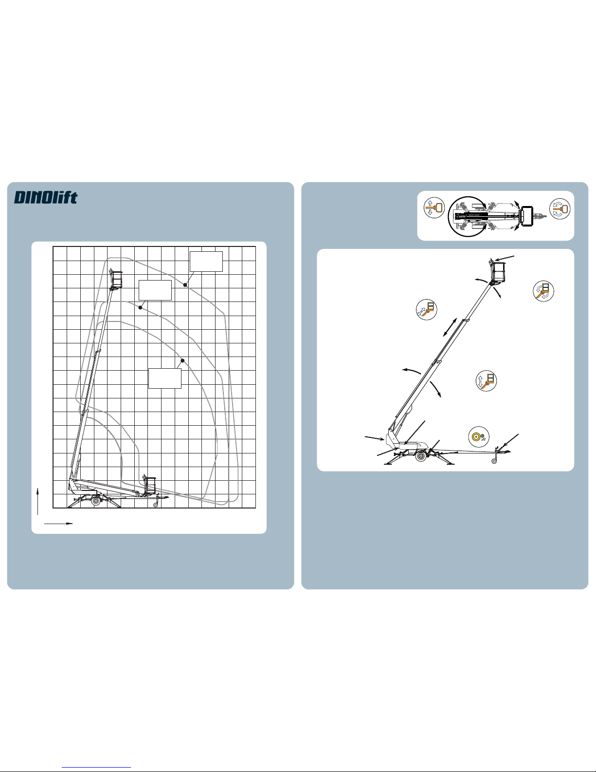
17
16
15
14
13
12
11
10
9
8
7
6
5
4
3
2
1
0
2 1 0 1 2 3 4 5 6 7 8 9 10
m
18
11 12
19
180T/TB
(80 kg)
150T/TB
(80 kg)
135T/TB
(120kg)
135TB 150TB 180TB
Weight 1765 kg 1835 kg 1945 kg
Transport height 2,16 m 2,24 m 2,18 m
Transport width 1,78 m 1,78 m 1,78 m
Support width 3,8 / 4,2 m 3,8 / 4,2 m 3,8 / 4,2 m
Lifting capacity 215 kg 215 kg 215 kg
LIFT FUNCTIONS
Left
Right
Boom rotation: continuous
Basket rotation: 90°
Basket
levelling
Boom lifting /
lowering
Driving device
Hand brake
Basket
rotation
Boom
rotation
Notice! Outreach depends on the platform load.
Telescope
UCB
LCB
Battery housings
NOTICE! This quick guide is a brief summary of the
use of DINO access platform and does not replace the
operating instructions for the device.
Read the operating instructions and make sure that
you understand all of the instructions and warnings
before using the device.
DAILY INSPECTIONS
• Check the condition of the work platform, boom and chassis structures
• Check the air pressure in the tyres and signs of damage
• Check the operation and condition of the lights
• Check hydraulic oil level and the condition of hydraulic hoses, pipes and ttings
• Check the safety limits function
• Check the emergency descent, emergency stop and sound signal
• Check that all adhesive tapes and plates are in place, intact and legible
• Check that the lift includes operating instructions and that they are legible.
Mains switch
(on the left side)
55 kg
MAX 215 KG
P
D
POWER SOURCE
Emergency descent with a hand pump
and manually operated valve (LCB)
Sound signal (UCB)
WORK SAFELY
Electric motor 3 kW, 24VDC
Batteries 4 x 6V, 235 Ah
Charging Mains current
Petrol engine
Safety functions:
NOTICE!
• Charge batteries at the end of the day. Keeping the
batteries discharged shortens their service life.
• Empty batteries freeze more easily
• Battery capacity is affected by operating temperature.
• If the engine does not start, make sure that none of
the emergency stop buttons has been pressed down.
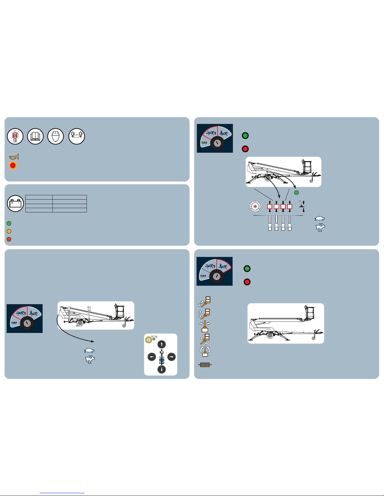
LIFT SUPPORT AND USE FROM THE CHASSIS CONTROL CENTRE
OPERATING THE LIFT FROM PLATFORM CONTROL CENTRE
4321
0
o
NOTICE! Support outriggers movements do not operate if the boom is not on the boom support.
NOTICE! The boom movements do not operate if the support outriggers are not rmly on the ground
Positioning and levelling:
• Make sure the ground is
even and sturdy enough. If
necessary, use additional
support plates.
• Lower the front support
outriggers
• Lower the rear support
outriggers
• Level the lift. The air
bubble in the level gauge
must be located inside the
inner ring.
• Make sure that the tyres
are properly off the ground
Telescope
in / out
Boom
up / down
Boom
rotation
Basket
rotation
Basket
levelling
Indicator lights:
The load is within outreach range.
Overload or the load at the outreach
range limit
The control panel symbols:
Max support force on
the outriggers:
135TB:
11300 N
(1150 kg)
150TB:
12800 N
(1300 kg)
180TB:
16800 N
(1700 kg)
Boom movements can also be used
from chassis contor center after the
outriggers are on the ground.
Battery gauge indicator lights
operating hours
ON: battery charge %
Flashes: battery charge is below 10%
Flashes: error code
Speed selector switch
for boom operation and
driving device (hold-to-run)
Emergency stop (UCB + LCB)
Start button for outrigger operation
Fuse
(basket rotation)
WARNING!
• The electrolyte is very corrosive!
• The battery generates hydrogen gas during charging.
Explosion hazard!
• This quick guide does not replace the operating
instructions. Read the operating instructions before
using the lift
• The lift operator must be over 18 years old
• The use of a faulty lift is strictly forbidden
• The use of the lift is forbidden if the temperature is
below -20oC and/or the wind speed over 12,5 m/s
• The lift must not be used as a crane
• Make sure the work area is free
• The maximum permissible load must not be
exceeded
• Never add load while in the upper position
• Maximum permitted lateral force load of 400 N
TOWING AND USING THE DRIVING DEVICE WITH THE LIFT IN THE TRANSPORT POSITION
Towing the lift
• Connect the ball-coupling and cable
• Connect the power line and check the
lights
• Release the parking brake
• Lift up the jockey wheel
• Make sure that the driving device is not
connected
Driving with the driving device
• The selector switch must be set to
"chassis control center"
• Switch the driving device to the
driving position
• Release the hand brake
• Drive the lift with the drive controls
• Beware of obstacles and power lines
The lift may only be moved in the transport position
• The boom lowered on the boom support
• The cover of the platform control centre closed
• Outriggers fully up
• No objects on the platform or the chassis
• Make sure that the electrical cable is disconnected or
the cable is long enough
Indicator lights:
The outrigger legs are supported and use
of the boom is permitted.
Overload or the load at the outreach range
limit
Before use
• Perform daily maintenance
procedures
• Check that the lift is
properly supported in a
level position
• Check the emergency stop
and the emergency descent
system
• Check the work area
While in operation
• Monitor the danger area
• Beware of high-voltage
power lines
• Do not climb onto the
platform railing
• Do not drop objects from
the platform
• If the overload indicator
lights up, retract the
telescope until the platform
is back in working range.
Speed selector switch for
boom operation and
driving device (hold-to-run)
 Loading...