

Dino AGP-1 Owner's Manual
AGP-1
Analog Guitar Effects Processor
World’s First Programmable Analog Multi-Effects
Owner’s Manual
(Version 3.1)
Copyright © 2009-2012 Tech-in-Mind Electronics
All rights reserved. No part of this publication may be reproduced in
any form without the permission of Tech-in-Mind Electronics.
website: www.tech-in-mind.com e-mail: sales@tech-in-mind.com
_______________________________________________________________________________________
3
Introduction
Thank you and congratulations on your choice of AGP-1 Analog Guitar Effects Processor. It is a
very innovative product and also a world’s first programmable analog multi-effects. By combining
both advantages of digital multi-effects (compact and convenience of use) and analog effect pedal
(natural and extremely good sound quality), this processor is launched with many amazing features
such as superior sound quality, small size, light weight, compact and very user friendly. This
processor contains three major parts:
Sound Management System (SMS)
(1) Accepts sound parameters and system settings from four user Rotate-Press knobs (located
below the LCD).
(2) Save/Load sound parameters and system settings.
(3) Command onboard and external plug-in analog sound modules.
(4) Organize different analog sound modules to form wide variety of guitar sound effects.
(5) Accepts commands of sound Bank/Patch switching, Patch/Pedal mode switching and Tuner
ON/OFF switching from five metal foot switches.
Analog Sound Modules
(1) They a re guitar signal processing devices operating with pure analog circuitry. They can be
looked like as tiny, highly integrated and compact guitar effect pedals.
(2) Their sound parameters and ON/OFF state are commanded by SMS.
(3) Ten sound module slots are available on main board. All plug-in analog sound modules can be
easily changed their plug-in location by user to form many thousands of combination and sound
effects.
Mixer
(1) Accepts external audio sources and mixes them together with your favor guitar eff ect sound to
form a volume-controllable audio signal output.
(2) Audio input can be either CD music, MP3, computer backing music like Guitar-Pro or an y other
sound source from electronic musical instruments.
(3) This processor pro vides three kinds of stereo audio output interface (RCA, XLR, 1/4” phone
jack) and one true-bypass mono output jack for guitar power amplifier.
(4) Four control knobs are used to facilitate the controls of metronome volume , guitar effect output
balance, external audio inputs volume and master audio output volume.
Product Features
(1) Total 20 groups of user settings storage, 4 Banks x 5 Patches.
(2) Each patch has its own Pedal-Mode. High flexibility in taking control of each analog sound
module's ON/OFF state.
_______________________________________________________________________________________
4
(3) 2.5” mono LCD display with blue backlight.
(4) Five heavy duty metal foot switches with LED indicator.
(5) Built-in guitar tuner.
(6) Built-in metronome with dual-color LED beat blinking.
(7) Built-in stereo headphone amplifier.
(8) Ten sound module plug-in slots and one external effect Send/Return Loop.
(9) Three onboard analog sound modules: 7-Bands Global Equalizer, Speaker Simulator, Stereo
Mixer.
(10) Many plug-in analog sound modules available for your choice: Compressor/NoiseGate,
Overdrive, Metal-Distortion, Hot-Distortion, Fuzz, Chorus, Flanger, Delay/Echo/Reverb,
Acoustic Simulator, Auto-Wah, Phaser, Octaver and Tremolo, and many more coming in future.
(11) All analog sound modules are turned ON/OFF by electro-mechanical true bypass switches.
(12) A very cost effective way to create many mo re analog guitar sound effects by plugging more
analog sound modules into sound module slots.
(13) Two external stereo audio input interfaces: RCA, 1/4” phone jack.
(14) Three stereo output interfaces: RCA, XLR, 1/4” phone jack.
(15) One true bypass mono output jack for guitar amplifier.
(16) Four Rotate-Press parameters control knobs.
(17) Four mixer control knobs.
(18) System firmware is upgradeable (using RS-232 on rear panel) by downloading latest firmware
from official website.
(19) Auto DC power polarity detection (center positive or center negative is not a concern).
(20) Wide range of DC voltage input: DC 9V to 12V, 1000mA or above.
(21) Dimensions: 33cm x 18cm x 5cm
(22) Weight: 2.5kg
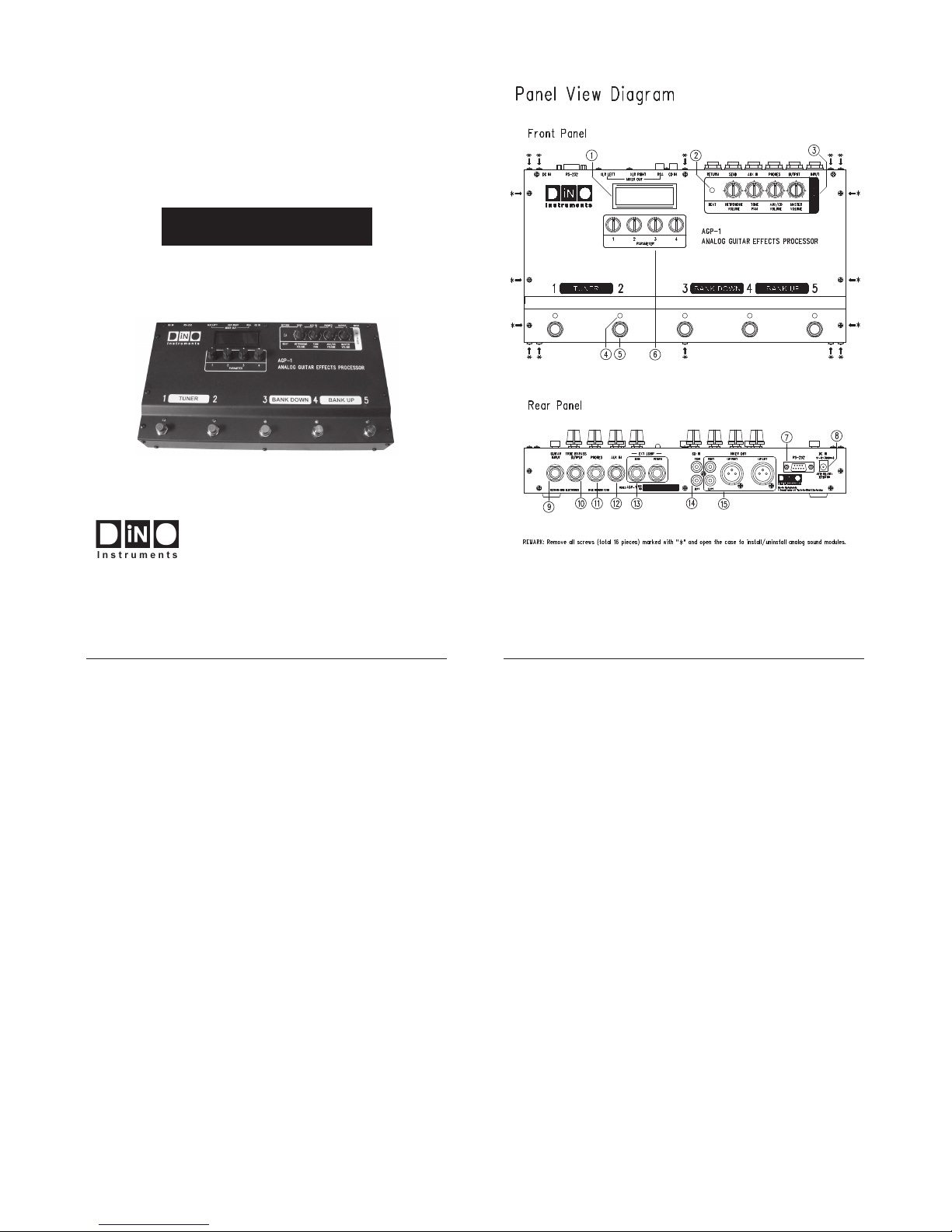
What They Are and What They Do
(Please refer to “Panel View Diagram”)
(1) LCD
Displays useful information like showing which Bank/Patch is in use, patch name, which analog
sound module is in use, and many others.
(2) Beat LED
Dual colors LED indicator for metronome, redĺ1
st
beat, blueĺ2nd to 4th beat.
(3) Mixer Control Knobs
Metronome Volume: Adjust the metronome volume.
NOTE: No metronome output to “True Bypass Output” if Mixer is OFF.
Tone Pan: Control guitar sound balance.
Rotate anticlockwise to shift guitar sound to left channel or rotate clockwise to shift guitar sound to
_______________________________________________________________________________________
5
right channel.
NOTE: This will only work for stereo output XLR, RCA and stereo phone jack, not applicable to
TRUE BYPASS OUTPUT jack.
AUX/CD Volume: Control AUX/CD input volume to mixer.
NOTE: TRUE BYPASS OUTPUT will only output this signal when Mixer is ON.
Master Volume: Control the mixed audio signals overall volume output. Setting to middle will have
1:1 gain ratio.
NOTE: Not applicable to “True Bypass Output” if Mixer is OFF.
(4) Patch LEDs
Indicates which patch is in use.
(5) Metal Foot Switches
Five switches are used for selecting different sound patch. Step 1 & 2 simultaneously to enter guitar
tuner mode, step 2 & 3 simultaneously to enter pedal mode, or step 3 & 4 for bank down or step 4 &
5 for bank up.
(6) Parameter Control Knobs
These 4 knobs can be rotated clockwise/anticlockwise or pressed for adjusting/selecting different
system variables and parameters.
(7) RS-232
Connect to PC COM port for firmware update.
(8) DC In
Auto polarity detection DC power input.
(9) Guitar Input
Connect to guitar output jack.
(10) True Bypass Output
Connect to guitar amplifier. It will be a true bypass output when mixer is disabled.
(11) Phones
Plug stereo headphone to this jack.
(12) AUX In
Connect to any external stereo audio signal source like MP3, electric musical instrument or
computer backing music.
_______________________________________________________________________________________
6
(13) Ext Loop Send/Return
Connect “Send” to external effect pedal’s input and “Return” to pedal’s output.
(14) CD In
Same as “AUX IN”, it will be disabled when there is a connector plugged into “AUX IN”.
(15) Mixer Out (RCA/XLR)
It is a mixed stereo signal output (guitar signal & external audio signal). RCA provides a convenient
way for sound connection. If superior sound quality is required for recording, two XLR connectors
are highly recommended to connect.
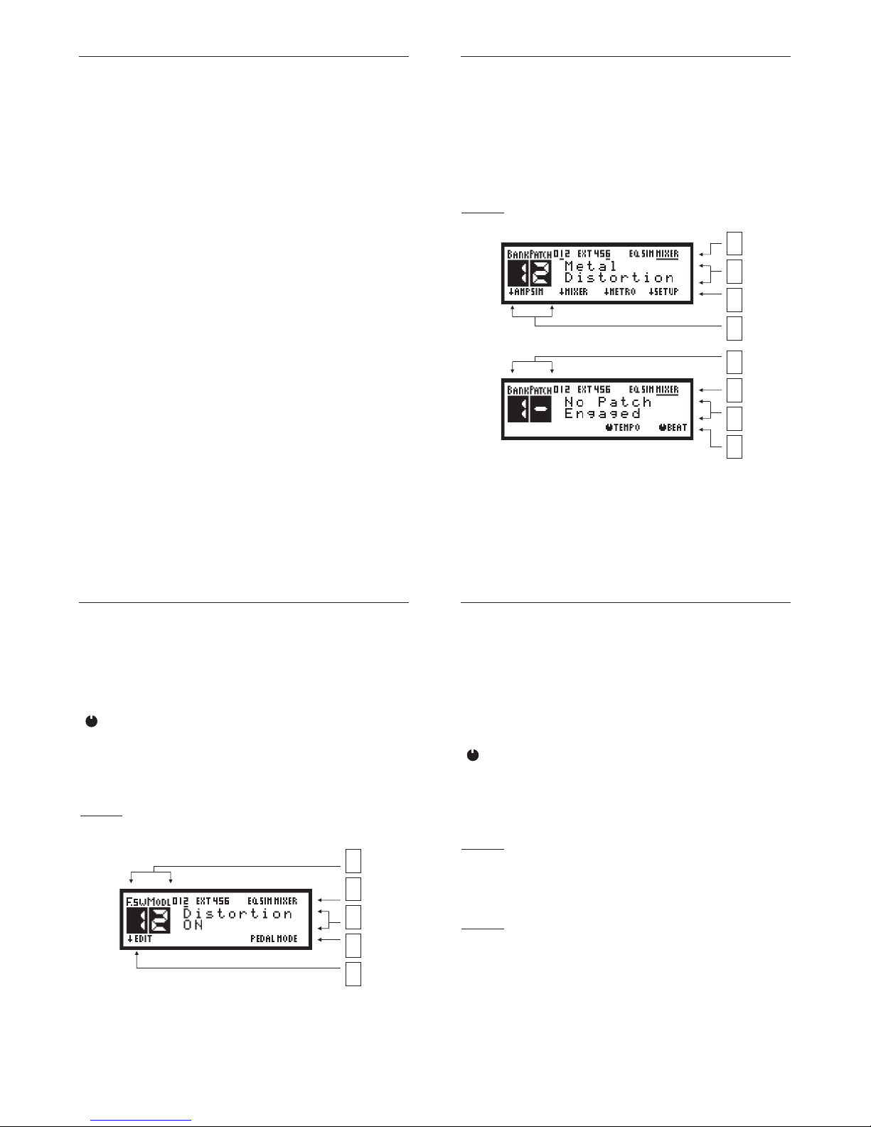
Understand the Useful Information on LCD
Patch-Mode
When you step 1 of 5 foot-switches, a patch is engaged and LCD shows below information:
Below information is shown when the patch is disengaged.
(Step the same foot-switch again)
(1) Analog Sound Module Icon
Numerical icon (0 to 9): Icons turned on indicate their corresponding sound module slot installed
with analog sound module.
EXT icon: External loop for external effect pedal.
EQ icon: Onboard analog sound module “7-Band Global Equalizer”.
1
2
3
4
1
2
3
4
_______________________________________________________________________________________
7
SIM icon: Onboard analog sound module “Speaker Simulator”.
MIXER icon: Onboard analog sound module “Stereo Mixer”.
Underline icon: Indicates the corresponding analog sound module turned on.
(2) Patch Name
Displays the name of current patch engaged. If no patch engaged, message “No Patch Engaged”
shown.
(3) Corresponding Function of 4 Rotate-Press Knobs
Rotate the knob clockwise or anticlockwise to adjust corresponding setting value.
Ļ Press the knob to select corresponding function.
(4) Bank/Patch Icon
Bank: Current bank of sound setting storage.
Patch: Current patch inside current bank, a dash mark “ņ“ indicates there is no patch engaged.
Pedal-Mode
Pedal-Mode allows player to have much more flexibility to take control of ON/OFF state of all
onboard sound modules and plug-in modules. Each Patch has its own pedal-mode settings. Player
can program each foot-switch to match up with any installed module.
(1) Foot-Switch & Module Number
Display what sound module is currently matched to the engaged foot-switch.
(2) Analog Sound Module Icon
Numerical icon (0 to 9): Icons turned on indicate their corresponding sound module slot installed
with analog sound module.
EXT icon: External loop for external effect pedal.
1
2
3
4
5
_______________________________________________________________________________________
8
EQ icon: Onboard analog sound module “7-Band Global Equalizer”.
SIM icon: Onboard analog sound module “Speaker Simulator”.
MIXER icon: Onboard analog sound module “Stereo Mixer”.
Underline icon: Indicates the corresponding analog sound module turned on.
(3) Module Name
Shows current module that is ON or OFF when a foot-switch is stepped.
(4) Pedal-Mode Icon
This blinking icon will appear when Pedal-Mode is activated.
(5) Corresponding Function of 4 Rotate-Press Knobs
Rotate the knob clockwise or anticlockwise to select which module to be matched to your
preferred foot-switch.
Ļ Press knob1 to edit module setting, or press knob2 to confirm foot-switch & module
matching and then exit pedal-mode setting.
Bank/Patch/Pedal-Mode Switching
Patch-Mode
Under the normal LCD manual display m ode, you can step any foot switch whenever you want to
engage a sound patch. This action will call out a group of settings (tone parameters and m odule
chain’s on/off state) of analog sound modules from AGP-1 system memory. Step the same foot
switch again to d isengage the current patch. Step foot-switch 3 & 4 sim ultaneously for bank down
or step foot switch 4 & 5 for bank up.
Pedal-Mode
When there is a patch engaged, step foot-switch 2 & 3 simultaneously to activate Pedal-Mode.
Step any one of five foot-switches to toggle ON/OFF of its corresponding module (assigned by
user). Step foot-switch 2 & 3 again to exit Pedal-Mode and go back to previous patch number.
Enable/Disable Onboard Speaker Simulator
Under the normal LCD manual display mode, press parameter knob 1 to enable/disable the
Speaker Simulator. The Speaker Simulator is very useful for standalone guitar sound recording or
mixed sound recording (both backing music and guitar sound) without the use of microphone to
pickup the sound from speaker cabinet or guitar power amplifier. It is also a cool feature that the
user can connect AGP-1 output directly to PA system for practice or onstage show.
 Loading...