

Dinli DL-901 Service Manual

【0-0】
F
OREWORD/INDE
X

【0-1】
F
OREWORD/INDEX
DINLI 450 cc Service Manual
All rights reserved. No parts of this publication may be reproduced, stored in a retrieval system,
or transmitted in any form or by any means, electronic mechanical photocopying, recording or
otherwise, without the prior written permission of Dinli Metal Industrial Co., Ltd..
No liability can be accepted for any inaccuracies or omissions in this publication, although
every possible care has been taken to make it as complete and accurate as possible.
The right is reserved to make changes at any time without prior notice and without incurring an
obligation to make such changes to products manufactured previously. See your dealer for the latest
information on product improvements incorporated after this publication.
All information contained in this publication is based on the latest product information available at
the time of publication.
Illustrations and photographs in this publication are intended for reference use only and may not
depict actual model component parts.
【0-2】
F
OREWORD/INDE
X
Foreword
This manual is designed primarily for use by trained mechanics in a properly equipped shop. A
basic knowledge of mechanics, the proper use of tools, and workshop procedures must be
understood in order to carry out maintenance and repair satisfactorily. In order to perform the work
efficiently and to avoid costly mistakes, read the text, thoroughly familiarize yourself with the
procedures before starting work, and then do the work carefully in a clean area. Precision
measurements can only be made if the proper instruments are used, and the use of substitute tools
may adversely affect safe operation.
For the duration of the warranty period, we recommend that all repairs and scheduled
maintenance be performed in accordance with this service manual. Any owner maintenance or
repair procedure not performed in accordance with this manual may void the warranty.
To get the longest life out of your vehicle:
● Follow the Periodic Maintenance Chart in the Service Manual.
● Be alert for problems and non-scheduled maintenance.
● Use proper tools and genuine DINLI vehicle parts. Genuine parts provided as spare parts are
listed in the Parts Catalog.
● Follow the procedures in this manual carefully. Don’t take shortcuts.
● Remember to keep complete records of maintenance and repair with dates and any replaced
parts.
How to Use This Manual
In preparing this manual, we divided the product into its major systems. These systems became
the manual’s chapters. All information for a particular system from adjustment through disassembly
and inspection is located in a single chapter.
The Quick Reference Guide shows you all of the product’s system and assists in location their
chapters. Each chapter in turn has its own comprehensive Table of Contents.
The Periodic Maintenance Chart is located in the General Information chapter. The chart gives a
time schedule for required maintenance operations.
If you want spark plug information, for example, go to the Periodic Maintenance Chart first.
The chart tells you how frequently to clean and gap the plug. Next, use the Quick Reference Guide
to locate the Electrical System chapter. Then, use the Table of Contents on the first page of the
chapter to find the Spark Plug section.
Whenever you see these WARNING and CAUTION symbols, heed their instructions! Always
follow safe operating and maintenance practices.
【0-3】
F
OREWORD/INDEX
△WARNING
This warning symbol identifies special instructions or procedures, which if not
correctly followed, could result in personal injury, or loss of life.
CAUTION
This caution symbol identifies special instructions or procedures, which if not
strictly observed, could result in damage to or destruction of equipment.
This manual contains four more symbols (in addition to WARNING and CAUTION), which
will help you distinguish different types of information.
NOTE
○ This note symbol indicates points of particular interest for more efficient and convenient
operation.
● Indicates a procedural step or work to be done.
○ Indicates a procedural sub-step or how to do the work of the procedural step it follows. It also
precedes the text of a NOTE.
★ Indicates a conditional step or what action to take based on the results of the test or inspection in
the procedural step or sub-step it follows.

【0-4】
F
OREWORD/INDE
X
CHAPTER INDEX
CHAPTER1 GENERAL
CHAPTER2 WHEELS/TIRES
CHAPTER3 BRAKE
CHAPTER4 SUSPENSION
CHAPTER5 FRAME
CHAPTER6 ENGINE
CHAPTER7 ELECTRICAL
CHAPTER8 APPENDIX

【0-5】
F
OREWORD/INDEX

【1-1】
GENERAL I
N
F
ORMATION
GENERAL INFORMATION
Table of Contents
Before Servicing------------------------------------------------------------------------------------------------1-2
Model Identifications----------------------------------------------------------------------------------------- 1-5
General Specifications-----------------------------------------------------------------------------------------1-6
Periodic Maintenance Chart----------------------------------------------------------------------------------1-8

【1-2】
GENERAL I
N
F
ORMATIO
N
Before Servicing
Before starting to perform an inspection service or carry out a disassembly and reassembly
operation on a quad, read the precautions given below. To facilitate actual operations, notes,
illustrations, photographs, cautions, and detailed descriptions have been included in each chapter
wherever necessary. This section explains the items that require particular attention during the
removal and reinstallation or disassembly and reassembly of general parts.
Especially note the following:
(1) Dirt
Before removal and disassembly, clean the quad. Any dirt entering the engine will shorten the
life of the quad. For the same reason, before installing a new part, clean off any dust or metal
fillings.
(2) Battery Ground
Disconnect the ground (-) wire from the battery before performing any disassembly operations
on the quad. This prevents the engine from accidentally turning over while work is being
carried out, sparks from being generated while disconnecting the wires from electrical parts, as
well as damage to the electrical parts themselves. For reinstallation, first connect the positive
wire to the positive (+) terminal of the battery.
(3) Installation, Assembly
Generally, installation or assembly is the reverse of removal or disassembly. However, if
installation or assembly sequence is given in this Service Manual, follow it. Note parts
locations and cable, wire, and hose routing during removal or disassembly so they can be
installed or assembled in the same way. It is preferable to mark and record the locations and
routing whenever possible.
(4) Tightening Sequence
When installing bolts, nuts, or screws for which a tightening sequence is given in this Service
Manual, mark sure to follow the sequence. When installing a part with several bolts, nuts, or
screws, start them all in their holes and tighten them to a snug fit, thus ensuring that the part has
been installed in its proper location. Then, tighten them to the specified torque in the tightening
sequence and method indicated. If tightening sequence instructions are not given, tighten them
evenly in a cross pattern. Conversely, to remove a pat, first loosen all the bolts, nuts, or screws
that are retaining the part a 1/4-turn before removing them.
(5) Torque
When torque values are given in this Service Manual, use them. Either too little or too much
torque may lead to serious damage. Use a good quality, reliable torque wrench.
(6) Force
Common sense should dictate how much force is necessary in assembly and disassembly. If a
part seems especially difficult to remove or install, stop and examine what may be causing the
problem. Whenever tapping is necessary, tap lightly using a wooden or plastic-faced mallet.
Use an impact driver for screws (particularly for the removing screws held by non-permanent

【1-3】
GENERAL I
N
F
ORMATION
locking agent) in order to avoid damaging the screw heads.
(7) Edges
Watch for sharp edges, as they could cause injury through careless handing, especially during
major engine disassembly and assembly. Use a clean piece of thick cloth when lifting the
engine or turning it over.
(8) High-Flash Point Solvent
A high-Flash point solvent is recommended to reduce fire danger. A commercial solvent
commonly available in North America is standard solvent (generic name). Always follow
manufacturer and container directions regarding the use of any solvent.
(9) Gasket, O-Ring
Replace a gasket or an O-ring with a new part when disassembling. Remove any foreign matter
from the mating surface of the gasket or O-ring to ensure a perfectly smooth surface to prevent
oil or compression leaks.
(10) Liquid Gasket, Locking Agent
Clean and prepare surfaces where liquid gasket or non-permanent locking agent will be used.
Apply them sparingly. Excessive amount may block engine oil passages and cause serious
damage.
(11) Press
When using a press or driver to install a part such as a wheel bearing, apply a small amount of
oil to the area where the two parts come in contact to ensure a smooth fit.
(12) Ball Bearing and Needle Bearing
Do not remove a ball bearing or a needle bearing unless it is absolutely necessary. Replace any
ball or needle bearings that were removed with new ones. Install bearings with the
manufacturer and size marks facing out, applying pressure evenly with a suitable driver. Apply
force only to the end of the race that contacts the press fit portion, and press it evenly over the
base component.
(13) Oil Seal and Grease Seal
Replace any oil or grease seals that were removed with new ones, as removal generally
damages seals. Oil or grease seals should be pressed into place using a suitable driver, applying
a force uniformly to the end of seal until the face of the seal is even with the end of the hole,
unless instructed otherwise. When pressing in an oil or grease seal, which has manufacturer’s
marks, press it in with the marks facing out.
(14) Cir-clip, Retaining Ring, and Cotter Pin
When installing cir-clips and retaining rings, take care to compress or expand them only
enough to install them and no more. Install the cir-clip with its chamfered side facing load side
as well. Replace any cir-clips, retaining rings, and cotter pins with new ones, as removal
weakens and deforms them, they could become detached while the quad is driven, leading to a
major problem.
【1-4】
GENERAL I
N
F
ORMATIO
N
(15) Lubrication
Engine wear is generally at its maximum while the engine is warming up and before all the
sliding surfaces have an adequate lubrication film. During assembly, make sure to apply oil to
any sliding surface or bearing that has been cleaned. Old grease or dirty oil could have lost its
lubrication quality and may contain forging particles that act as abrasives; therefore, make sure
to wipe it off and apply fresh grease or oil. Some oils and greases in particular should be used
only in certain applications and may be harmful if used in an application for which they are not
intended.
(16) Direction of Engine Rotation
To rotate the crankshaft manually, make sure to do so in the direction of positive rotation
Positive rotation is counterclockwise as viewed from the left side of the engine. To carry out
proper adjustment, it is furthermore necessary to rotate the engine in the direction of positive
rotation as well.
(17) Replacement Parts
When there is a replacement instruction, replace these parts with new ones every time they are
removed.
Always replace these parts with new ones every time they are removed. Although the
previously mentioned gasket, O-ring, ball bearing, needle bearing, grease seal, oil seal, cir-clip,
and cotter pin have not been so designated in their respective text, they are replacement parts.
(18) Electrical Wires
All the electrical wires are either one-color or two-color. A two-color wire is identified first by
the primary color and then the stripe color. For example, a yellow wire with thin red stripes is
referred to as a “yellow/red” wire; it would be a “red/yellow” wire if the colors were reversed.
Unless instructed otherwise, electrical wires must be connected to wires of the same color.
(19) Inspection
When parts have been disassembled, visually inspect these parts for the following conditions or
other damage. If there is any doubt as to the condition of them, replace them with new ones.
Abrasion Crack Hardening Warp
Bent Dent Scratch Wear
Color change Deterioration Seizure
(20) Specifications
Specification terms are defined as follows:
“Standards” show dimensions or performances which brand-new parts or systems have.
“Service Limits” indicate the usable limits. If the measurement shows excessive wear or
deteriorated performance, replace the damaged parts.
【1-5】
GENERAL I
N
F
ORMATION
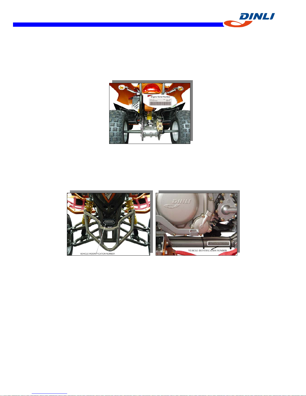
Model Identification
Engine serial number
Vehicle identification number
ENGINE SERIAL NUMBER (Ex. EW450SR00100000xxx)
VEHICLE IDENTIFICATION (ex. RFWAK85CX6Txxxxxx)
Whenever corresponding with DINLI about a particular issues, the engine number and serial
number are important for vehicle identification.
【1-6】
GENERAL I
N
F
ORMATIO
N
General Specification
NOTE:
Specifications subject to change without notice.
Model
DL901
Engine
4-stroke, DOHC
Bore and stroke 94mm x 64.6 mm
Compression ratio
11.6:1
Displacement 448 cc
Coolant system Liquid cooled
Coolant
1:1 water/anti-freeze[ethylene glycol(containing corrosion inhibitors
for aluminum engines and radiators)]
Starting system Electric
Carburetor Mikuni BSR42
Transmission 5-speed with reverse
Final drive 2WD/chain
Clutch type Manual Release, Multi Plate(8 plates), wet
Engine idle speed 1600 rpm
Spark plug, standard DCPR8E (NGK)
Spark plug gap 0.9 mm
Lubrication system Dry sump
Lubricant 4-cycle motorcycle engine oil 10W-40, Grade SF or higher
Ignition system
DC-CDI
Gasoilne 10.8 (Unleaded Automobile Premium Gasoline (Ron 98 or higher)
Alternator Output DC14V-13.7A @ 3000rpm
Thermostat Opening Temperature
71℃
Note: Permissible operating temperature: -10℃~45℃。
【1-7】
GENERAL I
N
F
ORMATION
CHASSIS
Frame Steel
Overall length 183 cm
Overall width 109 cm
Overall height 115 cm
Seat height 85 cm
Wheel base 1250 mm
Front tire 21 x 7 – 10
Rear tire 20 x 11 – 9
Recommended cold tire pressure (front/rear) 35kpa/ 35kpa
Turning radius 2.0m
Fuse 20A
Loading limit (Incl. rider, cargo, etc….) 200kg
Voltage 12V
Battery GS, GTX14-BS
Ground clearance, unloaded 200 mm
Water crossing maximum depth 575 mm
Front suspension travel 11”
Rear suspension travel 10”
Dry weight (approx KGs) 210
Fuel tank capacity 12L
Throttle lever free play 1~2 mm
Air filter Foam
Brake fluid DOT 4
Brake pad thickness (MIN) 2.0 mm
Brake disc thickness (MIN) 3.5 mm
Clutch lever free play (manual) 2 – 4 mm
Drive chain type 520 (O-ring type)
Drive chain slack 30 ~ 35mm
【1-8】
GENERAL I
N
F
ORMATIO
N
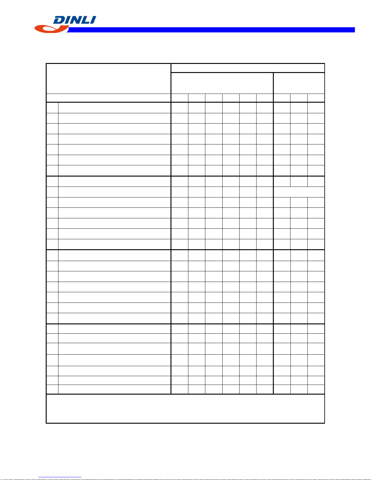
Periodic Maintenance Chart
Perform a Pre-Ride inspection before every ride and at schedule maintenance periods.
Interval (whichever comes first)
C=Clean
R=Replace
L=Lubricate
I=Inspect, Verify, Clean, Adjust, Lubricate, Replace if
necessary.
Regular Maintenance Interal (houre)
Regular Maintenance
(Riding Km)
Items
Break-in
(1 hour)
Inital
After 10 hr
Every 1
month
Every 3
month
Every 6
month
Note 200 Km 500Km 1000Km
WARNING LABELS (condition, readable) I I I I I I I I I
○
FRAME (mainframe,subframe,swingarm) I I I
▲
FUEL SYSTEM (hoses, tank, level) I I I
BATTERY (terminals) I,C I
▲
THROTTLE OPERATION I I I I
AIR FILTER I C C R
★
I I
AIRBOX DRAIN TUBE I,C I
★
I I
SPARK PLUG I R R
○
IDLE SPEED I I Adjust as required
▲
EXHAUST (spark arrester) C C
SWITCH (engine, stop, start, tether, ignition) I I
★
▲
LIGHTING (headlight, tail light, turning lights) I I
ENGINE OIL I R R
*
R R
ENGINE OIL FILTER(s) C R R R R
DRIVE CHAIN (sag, stretch, buffer, guide, sprockets
(condition/tightness), guards.
I I I
★
I
○
BRAKE FLUID I I
*
I
▲
BRAKE SYSTEM (cables, discs, pads, hoses, etc.) I I
★
I
BRAKE, REAR, DISC CARRIER I I I R I
▲
CLUTCH (lever, cable and arm position) I I I
COOLANT (radiator, cap, hoses, level, strength) I I R
*
I
SUSPENSION (front/rear shocks, condition, setting) I I I I
NUTS,BOLTS AND FASTENERS I I I I
○
SEAT (condition, wear, damage) I
▲
WHEELS/TIRES (pressure, condition, wear) I I I I I
SWINGARM (bearings) I I
★
▲
STEERING ASSEMBLY (fasteners, operation) I
★
I
A-ARM ( Bushing ball Joint) I
★
I
TIE ROD ENDS
I I I
★
▲DINLI dealer service suggested that servicing owners should have the proper tools, service data, and be mechanically qualified.
○Operational safety involved, The service should be performed by a DINLI dealer.
★Service more frequently if operation in dusty, sandy or snowy area or conditions.
*Change every 2 years.

【2-1】
WHEELS/TIRE
S
Wheels/Tires
Table of Contents
Specifications---------------------------------------------------------------------------------------------------2-2
Wheel Alignment-----------------------------------------------------------------------------------------------2-3
Steering Centering Inspection----------------------------------------------------------------------------2-3
Steering Centering Adjustment--------------------------------------------------------------------------2-3
Toe-in Inspection-------------------------------------------------------------------------------------------2-4
Toe-in Adjustment-----------------------------------------------------------------------------------------2-4
Wheels (Rims)--------------------------------------------------------------------------------------------------2-5
Wheel Removal--------------------------------------------------------------------------------------------2-5
Wheel Installation-----------------------------------------------------------------------------------------2-5
Wheel (Rim) Inspection-----------------------------------------------------------------------------------2-6
Wheel (Rim) Replacement-------------------------------------------------------------------------------2-6
Tires--------------------------------------------------------------------------------------------------------------2-6
Tires Removal--------------------------------------------------------------------------------------------2-6
Tires Installation------------------------------------------------------------------------------------------2-7
Tires Inspection-------------------------------------------------------------------------------------------2-8
Front Hub--------------------------------------------------------------------------------------------------------2-9
Front Hub Removal--------------------------------------------------------------------------------------2-9
Front Hub Installation-----------------------------------------------------------------------------------2-9
Rear Hub-------------------------------------------------------------------------------------------------------2-10
Real Hub Installation-----------------------------------------------------------------------------------2-10
Rear Hub Disassembly/Assembly--------------------------------------------------------------------2-10
【2-2】
WHEELS/TIRES
Specifications
Item Standard
Wheel Alignment: Toe-in 2WD
25~40 mm
Tires:
Standard tire: Front
Rear
Tire air pressure (when cold): Front
Rear
Maximum tire air pressure
(to seat beads, when cold)
AT 21×7-10
KENDA K300F-002, Tubeless
AT 20×11-9
KENDA K300-004, Tubeless
35 kPa (0.35 kgf/cm2, 5.0 psi)
35 kPa (0.35 kgf/cm2, 5.0 psi)
250 kPa (2.5 kgf/cm2, 36 psi)
【2-3】
WHEELS/TIRE
S
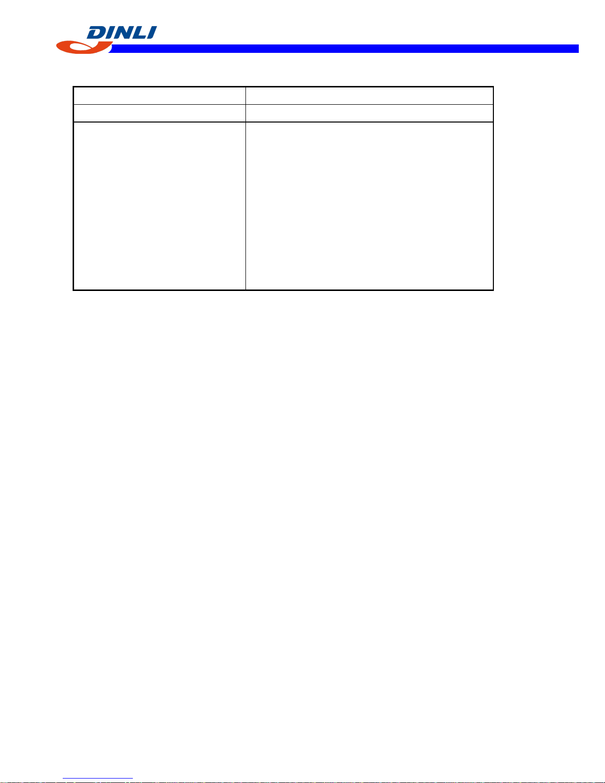
Wheel Alignment
Toe-in is the amount that the front wheels are closer
together in front than at the rear at the axle height. When there
is toe-in, the distance A (Rear) is the greater than B (Front) as
shown.
The purpose of toe-in is to prevent the front wheels from
getting out of parallel at any time, and to prevent any slipping
or scuffing action between the tires and the ground, if ton-in is
incorrect, the front wheels will be dragged along the ground,
scuffing and wearing the tread knobs. Measure the distance
between vehicle center and each wheel. This will tell you
which tie rod needs adjusting.
Caster and camber are build-in and require no adjustment.
A (Rear)-B (Front) = Amount of Toe-in
(Distance A and B are measured at axle height)
CAUTION:
During the tie rod adjustment, it is very important that the
precautions be taken when tightening tie rod end jam nuts.
Steering Centering Inspection
●Test ride the vehicle.
★If the handlebar is straight when the vehicle is traveling in a
straight line, go on to the Toe-in Inspection procedure.
★Otherwise, go on to the Steering Centering Adjustment
procedure.
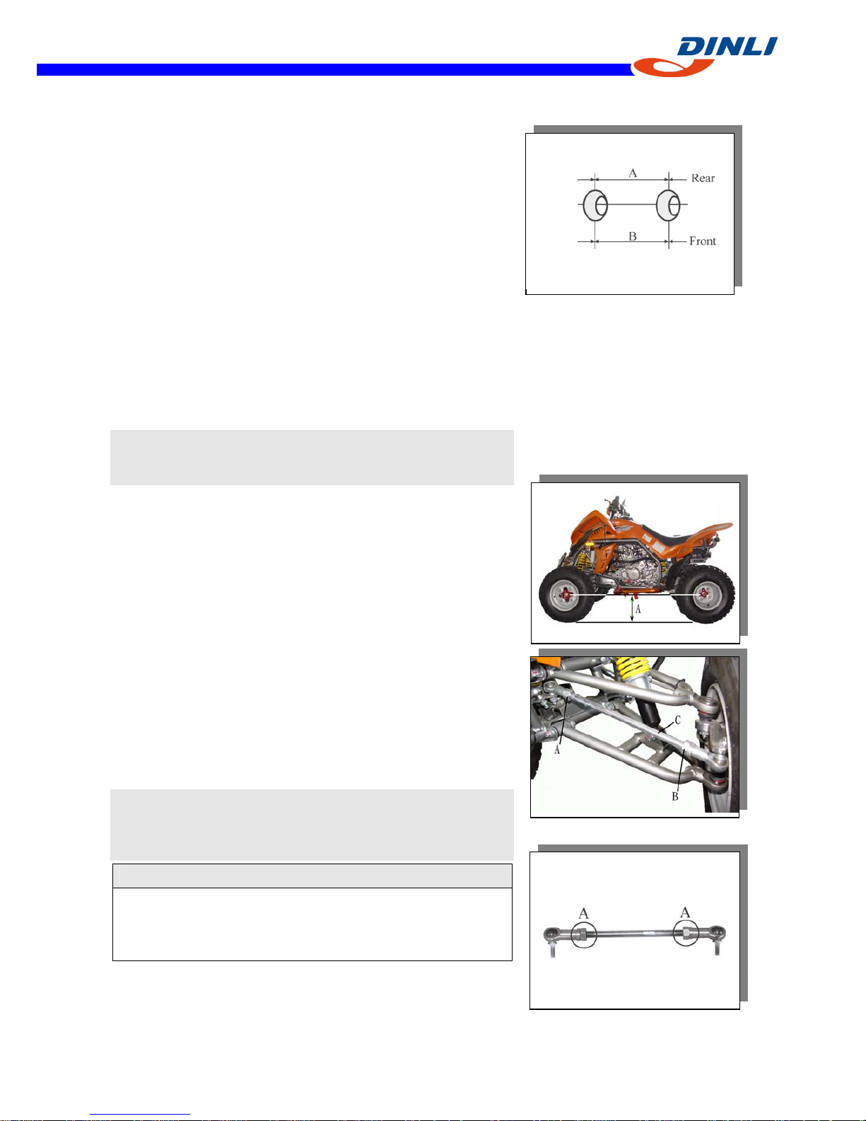
Steering Centering Adjustment
●Support the vehicle so that the front wheels are off the
ground and the front axles about the same height as the rear
axle.
○Hold a straightedge [A] against the rear wheel rim on one
side at axle height.
●With the handlebar straight ahead, loosen the locknuts [A]
[B] and Turn the tie-rod adjusting sleeve [C] until the front
wheel on that side is parallel to the straightedge.
NOTE
The locknut [A] on the tie-rod has left-hand threads. Turn the
wrench clockwise for loosening.
CAUTION
Adjust the tie-rod so that the visible thread length [A]is
even on both ends of the tie-rod, or the threads could be
damaged.
【2-4】
WHEELS/TIRES
●Repeat the straightedge procedure on the other side of the
vehicle, now the front wheels are parallel to each other and
to the center line of the vehicle.
●Go on to the Toe-in Inspection procedure.
Toe-in Inspection
●Support the vehicle on a stand or the jack so that the front
wheels are off the ground.
●Apply a heavy coat of the chalk near the center of the front
tires.
●Using a needle nose scriber, mark a thin mark near the
center of the chalk coating while turning the wheel.
●Keeping the front wheels off the ground, set the handlebar
straight ahead.
●At the level of the axle height, measure the distance
between the scribed lines for both front and rear of the front
tires.
●Subtract the measurement of the front from the
measurement of the rear to get the toe-in.
★If the toe-in is not in the specified range, go on to the
Toe-in adjustment procedure. Toe-in of Front Wheels
Standard:
Standard 0~2 mm
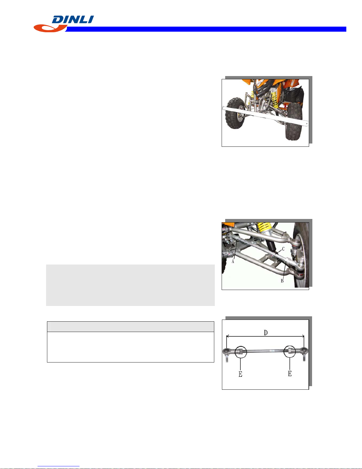
Toe-in Adjustment
● Loosen the locknuts [A] [B] and turn the adjusting sleeves
[C] the same number of turns on both sides to achieve the
specified toe-in.
NOTE
○The nut [A] on the tie-rod has left-hand threads. Turn the
nut clockwise for loosening.
○The toe-in will be near the specified value, if the tie-rod
length [D] is 385 mm on each tie-rod.
CAUTION
Adjust the tie-rod length so that the visible thread
length [E] is even on both ends of the tie-rod. Uneven
length could cause tie-rod damage.
【2-5】
WHEELS/TIRE
S
●Check the toe-in.
●Tighten:
Torque - Tie-Rod Adjusting Sleeve Locknuts: 33 N-m
(3.4 kgf-m, 45 ft-lb)
●Test ride the vehicle.
Wheels (Rims)
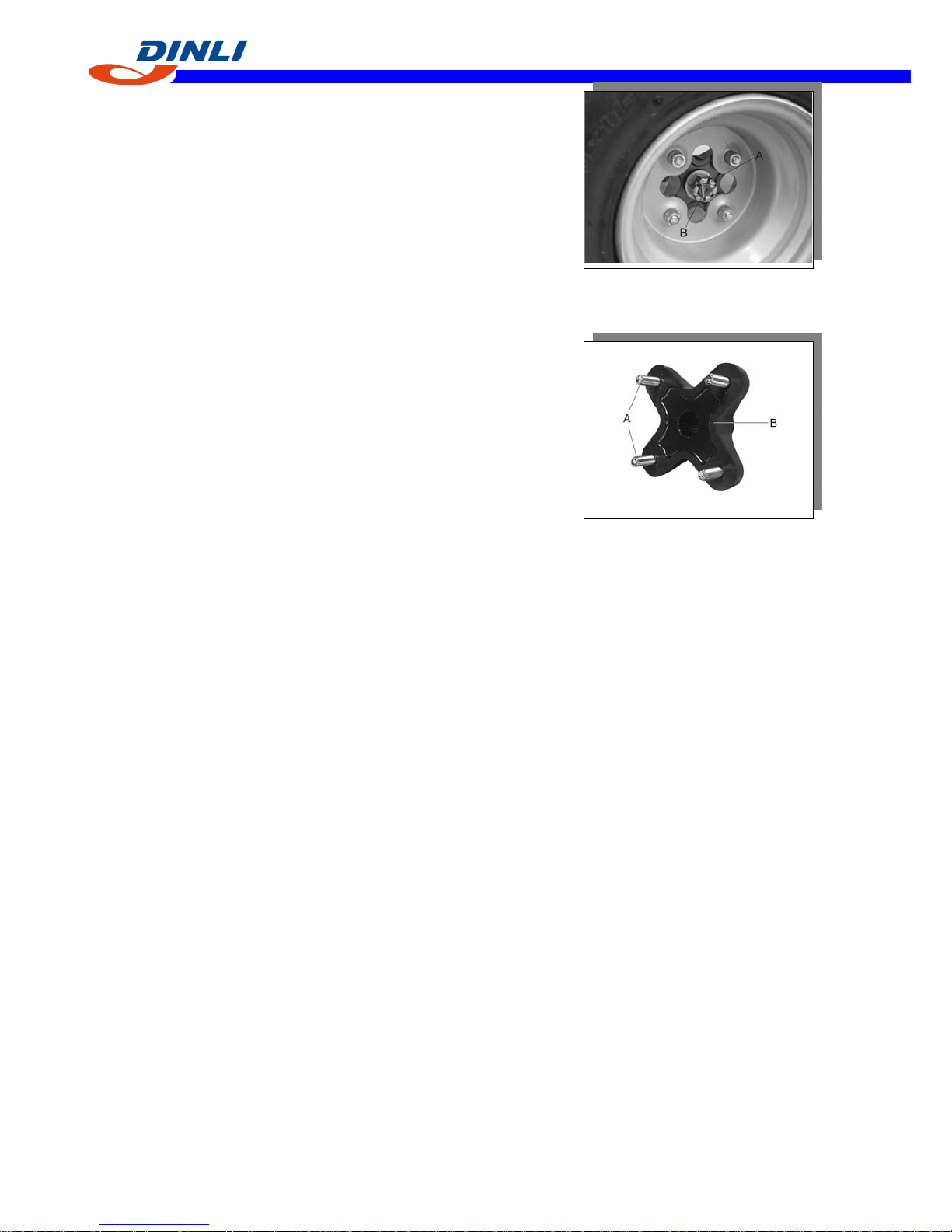
Wheel Removal
●Loosen the wheel nuts [A]
●Support the vehicle on a stand or the jack so that the wheels
are off the ground.
●Take off the wheel nuts and remove the wheel.
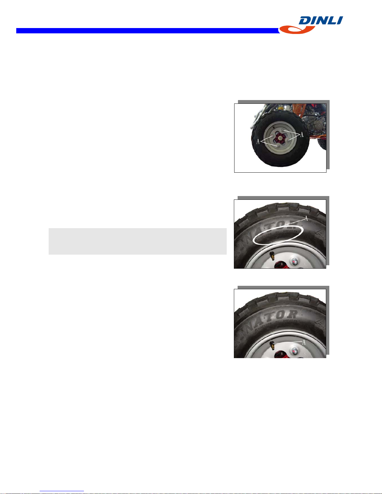
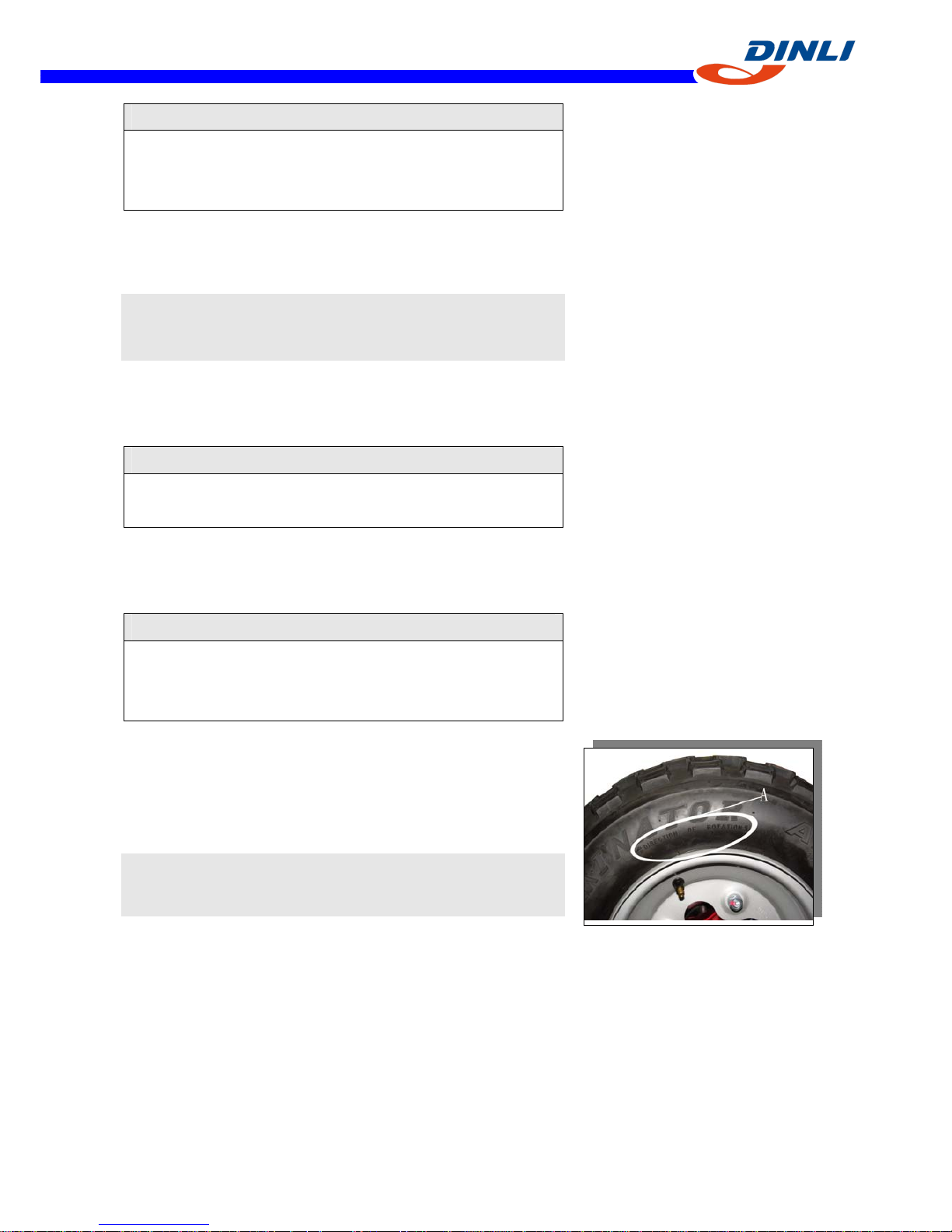
Wheel Installation
●Check the tire rotation mark [A] on the tire, and install the
wheel accordingly.
NOTE
○The direction of the tire rotation is shown by an arrow on
the tire sidewall.
●Position the wheel so that the air valve [A] is toward the
outside of the vehicle.
● Tighten the wheel nuts in a criss-cross pattern.
Torque- Wheel Nuts: 52 N-m (5.3 kgf-m, 38 ft-lb )
【2-6】
WHEELS/TIRES
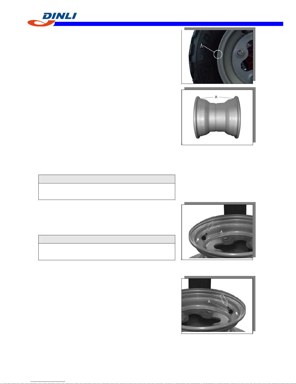
Wheel (Rim) Inspection
●Examine both sides of the rim for dents [A]. If the rim is
dented, replace it.
●If the tire is removed, inspect the air sealing surfaces [A] of
the rim for scratches or nicks. Smooth the sealing surfaces
with fine emery cloth if necessary
Wheel (Rim) Replacement
●Remove the wheel (see Wheel Removal)
●Disassemble the tire from the rim (see Tire Removal).
○Remove the air valve and discard it.
CAUTION
Replace the air valve whenever the tire is replaced. Do
not reuse the air valve.
●Install a new air valve in the new rim.
○Remove the valve cap, lubricate the stem with a soap and
water solution, and pull the stem [A] through the rim from
the inside out until it snaps into place.
CAUTION
Do not use engine oil or petroleum distillates to lubricate
the stem because they will deteriorate the rubber.
●Mount the tire on the new rim (see Tire Installation).
●Install the wheel (see Wheel Installation).
TIRES
Tire Removal
●Remove the wheel.
●Unscrew the valve core to deflate the tire.
○Use a paper valve core tool.
●Lubricate the tire beads and rim flanges on both sides of the
wheel with a soap and water solution, or water. This helps
the tire beads slip off the rim flanges.
【2-7】
WHEELS/TIRE
S
CAUTION
Do not lubricate the tire beads and rim flanges with
engine oil or petroleum distillates because they will
deteriorate the tire.
●Remove the tire from the rim using a suitable commercially
available tire changer.
NOTE
○The tires cannot be removed with hand tools because they
fit the rims tightly.
Tire Installation
●Inspect the rim (see Wheel (Rim) Inspection).
●Replace the air valve with a new one.
CAUTION
Replace the air with whenever the tire is replaced. Do
not reuse the air valve.
●Check the tire for wear and damage (see Tire Inspection)
●Lubricate the tire beads and rim flanges with a soap and
water.
△WARNING
Do not use the lubricant other than a water and soap
solution, or water to lubricate the tire beads and rim
because it may cause tire separation.
●Check the tire rotation mark [A] on the tire, and install the
tire on the rim accordingly.
○The tires should be installed on the rims so that each air
valve is toward outside of the vehicle.
NOTE
○The direction of the tire rotation is shown by an arrow on
the tire sidewall.
●Install the tire on the rim using a suitable commercially
available tire changer.
●Lubricate the tire beads again and center the tire on the rim.
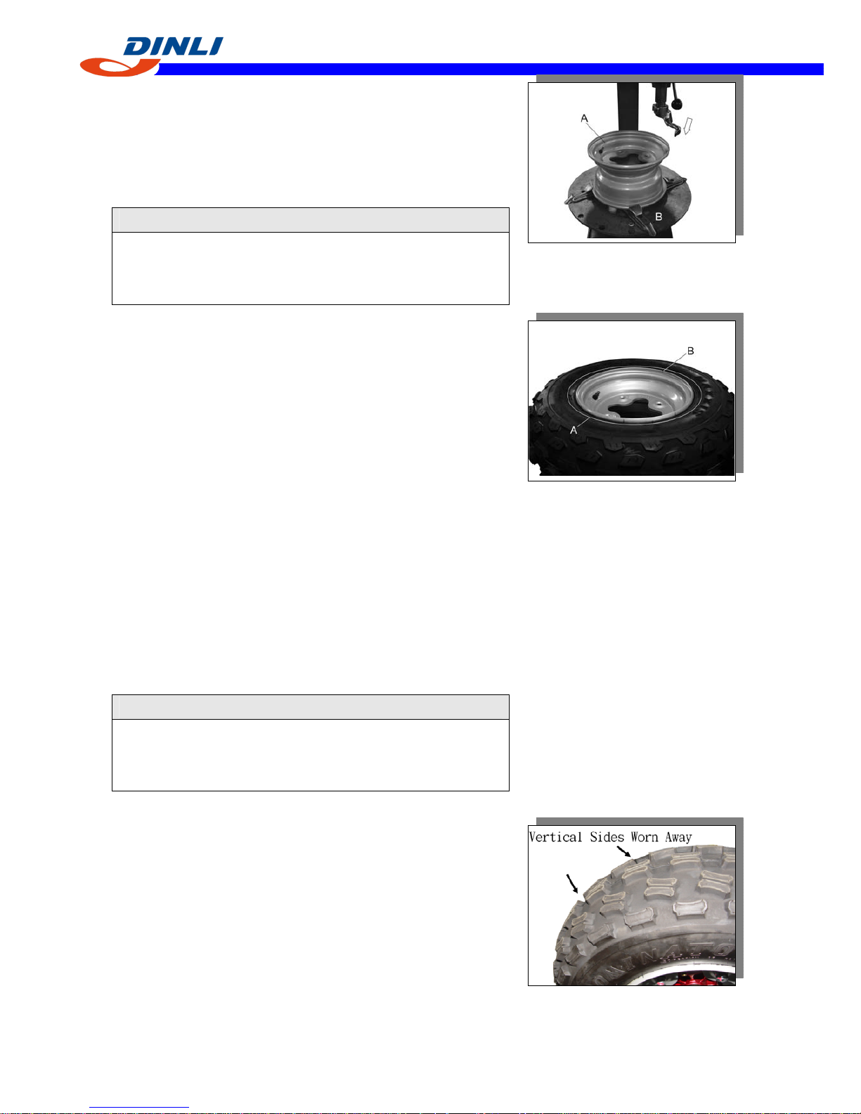
【2-8】
WHEELS/TIRES
●Support the wheel rim [A] on a suitable stand [B] to
prevent the tire from slipping off.
●Inflate the tire until the tire beads seat on the rim.
Maximum Tire Air Pressure ( to seat beads when cold )
Front and Rear: 250kpa (2.5 kgf-cm2, 36 psi )
△WARNING
Do not inflate the tire to more than the maximum tire
air pressure. Over inflation can explode the tire with
possibility of injury and loss of line.
●Check to see that rim lines [A] on both sides of the tire are
parallel with the rim flanges [B].
★If the rim lines and the rim flanges are not paralleled,
deflate the tire, lubricate the sealing surfaces again, and
re-inflate the tire.
●After the beads are properly seated, check for air leaks.
○Apply a soap and water solution around the tire bead and
check for bubbles.
●Deflate the tire to the specified pressure.
●Check the tire pressure using an air pressure gauge.
Tire Air Pressure (when cold)
Front: 50 kPa (7.0 psi)
Rear: 50 kPa (7.0 psi)
●Install the wheel (see Wheel Installation).
●Wipe off the soap and water solution on the tire and dry the
tire before operation.
△WARNING
Do not operate the vehicle with the water and soap still
around the tire beads. They will cause tire separation,
and a hazardous condition may result.
Tire Inspection
●Examine the tire for damage and wear.
○If the tire is cut or cracked, replace it.
○Lumps or high spots on the tread or sidewalls indicate
internal damage requiring tire replacement.
○Remove any foreign objects from the tread. After removal,
check for leaks with a soap and water solution.
○Check the shape of the tread knobs. If no vertical side is left
on the drive side of the knobs, replace the tire.
【2-9】
WHEELS/TIRE
S
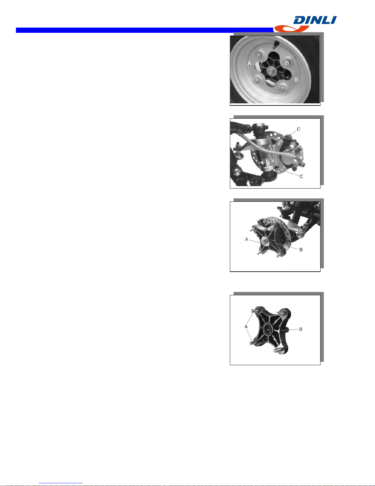
Front Hub Removal
●Remove the cotter pin [A] and loosen the axle nut [B].
●Remove the wheel (see Wheel Removal).
●Remove the caliper by taking off the mounting bolts [C],
and let the caliper hang free.
●Remove the axle nut and pull off the front hub brake disc.
●Separate the brake disc from the front hub.
Front Hub Installation
●Grease::
Seal
Front Spindle
●Tighten:
Torque - Front Spindle Nut: 145 N-m (15.0 kgf-m, 110
ft-lb )
●Insert a new cotter pin [A] and bead it over the nut [B]
Front Hub Disassembly/Assembly
●Don not press the hub bolts out.
★If any hub bolt [A] is damaged, replace the hub [B] and
bolts as a unit.
【2-10】
WHEELS/TIRES
Rear Hub
Rear Hub Installation
●Grease the axle spindle.
●Apply non-permanent locking agent: Rear Axle Nuts [A]
●Tighten:
Torque - Rear Axle Nut: 265 N-m (27.0 kgf-m, 195ft-lb)
●Insert a new cotter pin [B] and bend it over the nut.
Rear Hub Disassembly/Assembly
●Do not press the hub bolts [A] out.
★If any hub bolt is damaged, replace the hub [B] and bolts as
a nut.

【3-1】
BRAK
E
Brake
Table of Contents
Brake Fluid-----------------------------------------------------------------------------------------------------3-2
Brake Fluid Recommendation-------------------------------------------------------------------------3-2
Brake Fluid Level Inspection--------------------------------------------------------------------------3-3
Brake Fluid Change-------------------------------------------------------------------------------------3-3
Brake Line Air Breeding-------------------------------------------------------------------------------3-4
Master Cylinder-----------------------------------------------------------------------------------------------3-5
Master Cylinder Removal------------------------------------------------------------------------------3-5
Master Cylinder Installation---------------------------------------------------------------------------3-5
Calipers---------------------------------------------------------------------------------------------------------3-6
Calipers Removal----------------------------------------------------------------------------------------3-6
Calipers Installation-------------------------------------------------------------------------------------3-6
Brake Pads------------------------------------------------------------------------------------------------------3-7
Brake Pads Removal------------------------------------------------------------------------------------3-7
Brake Pads Installation----------------------------------------------------------------------------------3-7
Brake Pads Wear Inspection----------------------------------------------------------------------------3-7
Brake Discs-----------------------------------------------------------------------------------------------------3-8
Disc Cleaning---------------------------------------------------------------------------------------------3-8
Disc Removal---------------------------------------------------------------------------------------------3-8
Disc Installation------------------------------------------------------------------------------------------3-8
Disc Wear Inspection------------------------------------------------------------------------------------3-8
Disc Runout-----------------------------------------------------------------------------------------------3-9
Brake Hoses-----------------------------------------------------------------------------------------------------3-9
Brake Hose Inspection-----------------------------------------------------------------------------------3-9
Brake Hose Replacement--------------------------------------------------------------------------------3-9
Rear Brake-----------------------------------------------------------------------------------------------------3-10
Brake Pedal Position Inspection----------------------------------------------------------------------3-10
Brake Pedal Position Adjustment---------------------------------------------------------------------3-10
Brake Pedal Free Play Inspection---------------------------------------------------------------------3-10
Brake Pedal Removal----------------------------------------------------------------------------------3-10
Brake Pedal Installation--------------------------------------------------------------------------------3-11
Caliper Removal----------------------------------------------------------------------------------------3-11
Caliper Installation--------------------------------------------------------------------------------------3-11
Rear Brake Pads Removal-----------------------------------------------------------------------------3-12
Rear Brake Pads Installation--------------------------------------------------------------------------3-12
Master Cylinder Removal-----------------------------------------------------------------------------3-13
Master Cylinder Installation---------------------------------------------------------------------------3-13
Brake Disc Removal------------------------------------------------------------------------------------3-14
Brake Disc Installation---------------------------------------------------------------------------------3-14
【3-2】
B
RAKE
Brake Fluid
WARNING△
When working with the disc brake, observe the precautions
listed below.
1.Never reuse old brake fluid.
2.Do not use fluid from a container that has been left unsealed or that has or that has been
open for a long time.
3.Do not mix two types and brand of fluid for use in the brake. This lowers the brake fluid
boiling point and could cause the brake to be ineffective. It may also cause the rubber brake
parts to deteriorate.
4.Don't leave the reservoir cap off for any length of time to avoid moisture contamination of the
fluid.
5.Don't change the fluid in the rain or when a strong wind is blowing.
6.Except for the disc pads and disc, use brake fluid, isopropyl alcohol, or ethyl alcohol for
cleaning brake parts. Do not use any other fluid for cleaning these parts. Gasoline, engine
oil, or any other petroleum distillate will cause deterioration of the rubber parts. Oil spilled
on any parts will be difficult to wash off completely and will eventually deteriorate the rubber
used in the disc brake.
7.When handing the disc pads or disc, be careful that no disc brake fluid or any oil gets on
them. Clean off any fluid or oil that inadvertently gets on the pads or disc with a high
flash-point solvent. Replace the pads with new ones if they cannot be cleaned satisfactorily.
8.Brake fluid quickly ruins painted surface; any spilled fluid should be completely washed away
immediately.
9.If any of the brake line fittings or the bleed valve is opened at any time, the AIR MUST BE
BLED FROM THE BRAKE LINE.
Brake Fluid Recommendation
Recommended fluid is given in the table below. If none of the recommended fluid is
available, use extra heavy-duty brake fluid only from a container marked DOT 3 or 4.
【3-3】
BRAK
E
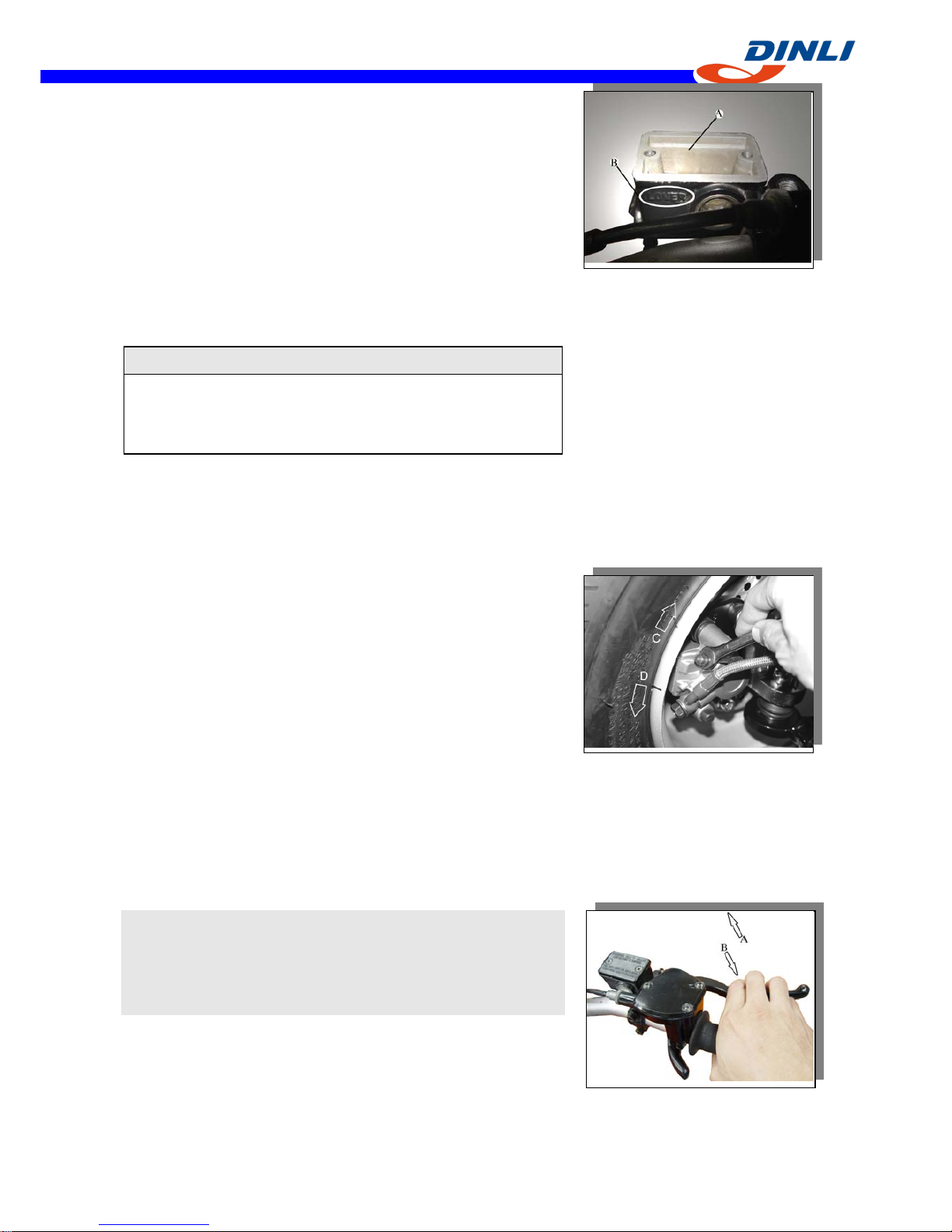
Brake Fluid Level Inspection
●Position the reservoir horizontal, and check that the fluid
level in the reservoir is higher than the lower level line [B].
If the fluid level is lower than the lower level line, check ★
for fluid leakage of the brake line, and add the fluid as
follow.
○Removal the reservoir cap, and fill the reservoir to the
upper level line [A] in the reservoir with the same type and
brand of the fluid that is already in the reservoir.
And then install the reservoir cap.
WARNING△
Change the fluid in the brake line completely if the fluid
must be refilled but the type and brand of the fluid that is
already in the reservoir are unidentified.
●Tighten:
Torque - Reservoir Cap Screws: 1.5 N-m (0.15 kg-m, 13
in-lb)
Brake Fluid Change
●Removal the reservoir cap and the rubber cap on the bleed
valve.
●Attach a clear plastic hose to the bleed valve on the caliper,
and run the other end of the hose into a container.
●Fill the reservoir with new brake fluid.
●Change the brake fluid as follows:
○Open the bleed valve [A].
○Apply the brake level and hold it [B].
○Close the bleed valve [C].
○Release the brake level [D].
●Check the fluid level in the reservoir often, replenishing it
as necessary.
NOTE
○If the fluid in the reservoir runs completely out any time
during fluid change, air will enter the line, and the system
must be bled.
●Repeat this operation until fresh brake fluid comes out into
the plastic hose or the color of the fluid change.
【3-4】
BRAKE
WARNING△
Do not mix two brand of fluid. Change the brake fluid in
the brake line completely if the fluid must be refilled but
the type and brand of the brake fluid that is already in
the reservoir are unidentified.
●Tighten:
Torque - Bleed Valve: 5.4 N-m (0.55 kg-m, 48 in-lb)
●Apply the brake lever forcefully for a few second, and
check for fluid leakage around the fittings.
WARNING△
If the brake lever has a soft or "spongy feeling" when it is
applied, there might be air in the brake line or the brake
may be defective. Since it is dangerous to operate the
vehicle under such condition, bleed the air from the brake
line immediately.
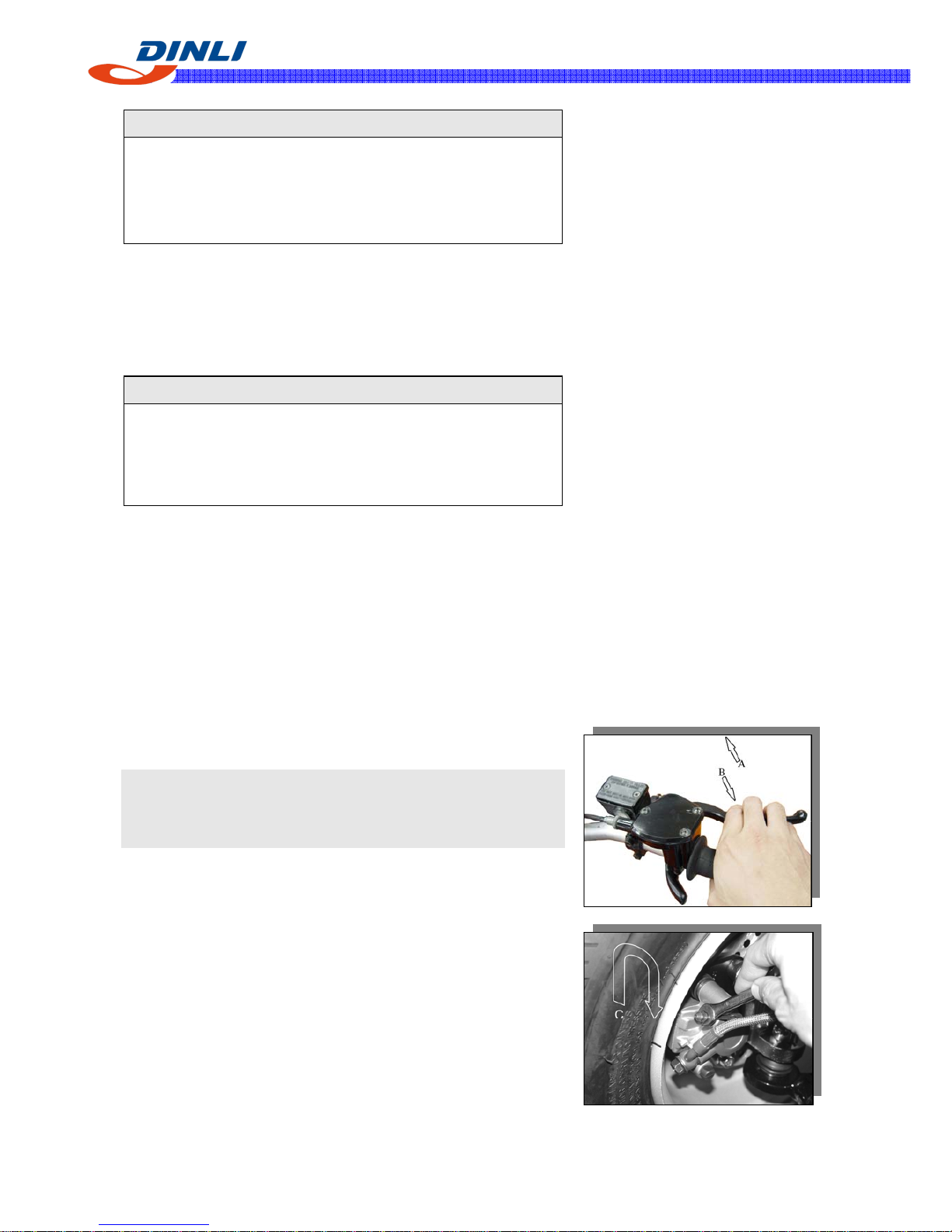
Brake Line Air Bleeding
●Bleed the air whenever brake parts are replaced or
reassembled.
●Remove the reservoir cap and fill the reservoir with new
brake fluid.
●Slowly pump the brake lever several times until no air
bubbles can be seen rising up through the fluid from the
hose at the bottom of the reservoir. This bleeds the air from
the master cylinder and the brake line.
NOTE
○Tap the brake hose lightly going from the caliper to the
reservoir side and bleed the air off at the reservoir.
●Attach a clear plastic hose to the bleed valve on the caliper,
and run the other end of the hose into a container.
●Bleed the brake line and the caliper as follows:
○Hold the brake level applied [B].
○Quickly open and close the valve [C].
○Release the brake level [A].
●The fluid level must be checked several times during the
bleeding operation and replenished as necessary.
【3-5】
BRAK
E
NOTE
○If the fluid in the reservoir runs completely out any time
during bleeding, the bleeding operation must be done over
again from the beginning since air will have entered the
line.
○If the brake level action still feels soft or "spongy", tap the
brake hose from bottom to top and air will rise up to part of
the hose. Slowly pump the brake level in the same manner
as above.
●Tighten:
Torque - Bleed Valves: 5.4 N-m (0.55 kg-m, 48 in-lb)
●Apply the brake level forcefully for a few seconds, and
check for fluid leakage around the fittings.
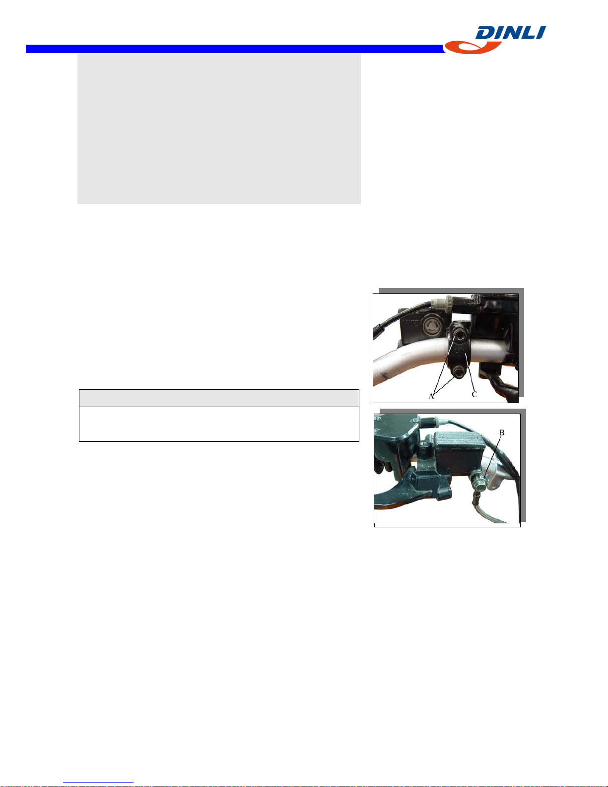
Master Cylinder Removal
●Removal:
Brake Hose Banjo Bolt [B]
Master Cylinder Clamp Bolts [A]
Master Cylinder
CAUTION
Brake fluid quickly ruins painted surface; any spilled fluid
should be completely washed away immediately.
Master Cylinder Installation
●The master cylinder clamp must be installed with the "UP"
mark [C] upwards.
●Tighten the upper clamp bolt first, and then the lower clamp
bolt. There will be a gap at the lower part of the clamp after
tightening.
Torque - Master Cylinder Clamp Bolts:
8.8N-m(0.90kg-m,78in-lb)
●Use a new flat washer on each side of the brake hose
fitting, and tighten the banjo bolt.
Torque - Brake Hose Banjo Bolt:25N-m(2.5kg-m,18.0ft-lb)
●Bleed the brake line after master cylinder installation (see
Brake Line Air Bleeding).
●Check the brake for good braking power, no braking brag,
and no fluid leakage.
 Loading...