

Dini Argeo DFWATEX2GD, DFWATEX2GDIO, DFWATEX2GDM, DFWATEX2GDMI Technical Manual
TECHNICAL MANUAL
WEIGHT INDICATOR
DFWATEX2GD, DFWATEX2GDIO, DFWATEX2GDM,
DFWATEX2GDMI
DFWATEX2GD_05.03_12.09_EN_T
1 of 49

INDEX
1 WARNINGS ........................................................................................................................................................................ 3
2 REQUIREMENTS FOR AN EFFECTIVE INSTALLATION ................................................................................................. 4
3 TECHNICAL FEATURES ................................................................................................................................................... 4
4 SETUP ENVIRONMENT ..................................................................................................................................................... 5
4.1 SET-UP ENVIRONMENT BLOCK DIAGRAM ............................................................................................................... 7
4.2 DESCRIPTION OF THE STEPS ................................................................................................................................... 9
5 CALIBRATION .................................................................................................................................................................. 21
5.1 SCALE CONNECTED TO A SINGLE CHANNEL ....................................................................................................... 22
5.2 SCALE WITH NON INDEPENDENT CHANNELS (could eventually be digitally equalised) ....................................... 22
5.3 IF THE ZONE OF USE IS DIFFERENT THAN THE CALIBRATION ZONE ONE SHOULD: ...................................... 23
5.4 QUICK CALIBRATION OF ZERO ............................................................................................................................... 24
5.5 QUICK CALIBRATION OF A DEFINED WEIGHT ...................................................................................................... 24
5.6 MANUAL CALIBRATION OF A DEFINED WEIGHT ................................................................................................... 24
6 DISPLAY OF THE GRAVITY ACCELERATION AND CORRECTION OF THE WEIGHING ERROR DUE TO THE
DIFFERENT GRAVITY ACCELERATION BETWEEN CALIBRATION ZONE AND UTILISATION ZONE. ......................... 25
7 SERIAL OUTPUT .............................................................................................................................................................. 25
7.1 FIBER OPTIC PORT .................................................................................................................................................. 25
7.2 SERIAL PORT TRANSMISSION MODES .................................................................................................................. 25
7.2.1 PC PORT ............................................................................................................................................................. 25
7.2.2 PRN PORT ........................................................................................................................................................... 28
7.3 FORMAT OF THE SERIAL COMMANDS ................................................................................................................... 28
7.4 TRANSMISSION PROTOCOLS ................................................................................................................................. 34
7.4.1 STANDARD STRING ........................................................................................................................................... 34
7.4.2 EXTENDED STRING ........................................................................................................................................... 35
7.4.3 MASTER MODE STRINGS .................................................................................................................................. 36
8 PROGRAMMING THE PRINTOUTS ................................................................................................................................. 36
8.1 FORMATTING DATA AND LAYOUT .......................................................................................................................... 39
8.2 SAVING THE LABEL IN THE LABELLER’S PERMANENT MEMORY ....................................................................... 45
8.2.1 SAVING THE LABEL IN THE LABELLER’S PERMANENT MEMORY IN MASTER/SLAVE SYSTEMS ............. 45
9 PRINTING THE HEADING ................................................................................................................................................ 46
10 CONNECTION SCHEMES .............................................................................................................................................. 49
10.1 EXPLANATION OF EXPANSION BOARDS (PRESENT DEPENDING ON THE MODEL) ...................................... 49
For the simplest usage in this manual, the name DFWATEX stands for both DFWATEX2GD, DFWATEX2GDIO,
DFWATEX2GDM and DFWATEX2GDMI,
so where “DFWATEX” is used it is understood as “DFWATEX2GD, DFWATEX2GDIO, DFWATEX2GDM and
DFWATEX2GDMI”.
NOTE FOR THE TECHNICIAN
Please take note that when the “StEP….(USER MAN.REF.)is mentioned, this refers to the user manual.
DFWATEX2GDxxx 2 of 49
1 WARNINGS
These warnings apply to DFWATEX2GDxxx weight indicators and
to the optional ATEX version JB4Q junction box
ESSENTIAL PREREQUISITE
ALONG WITH THIS TECHNICAL MANUAL ONE SHOULD
ALSO READ AND UNDERSTAND THE CORRESPONDING
DFWATEX2GD USER MANUAL
IN WHICH IMPORTANT WARNINGS ARE INDICATED
DFWATEX2GDxxx 3 of 49
POWER SUPPLY
- with power adapter PW200XRD:
- 230Vac input / 10.5Vdc
- 115Vac input / 10.5Vdc
- 24Vac input / 10.5Vdc
- 24Vdc input / 10.5Vdc
- with rechargeable battery DFWBP76ATEX: 9,6 Vdc
120mA with a nominal capacity of 7,6 Ah
MAXIMUM RECHARGING TIME OF THE
BATTERY
With the appropriate 12V 2A charger, the complete recharge
is made from 15 to 18 hours
MAXIMUM POWER ABSORBED
Pi = 1,44W
OPERATING TEMPERATURE
- 20°C ÷ +40°C
DISPLAY DIVISIONS
10000e, 3 x 3000e for legal for trade weighing, expandable up
to 100.000 for internal use.
COUNTING RESOLUTION
150'000 points
DISPLAY
LCD with 6 digits, 25 mm. high
INDICATIONS
25 multifunction symbols on LCD display
KEYBOARD
Waterproof in polycarbonate with membrane keys having a
tactile and acoustic feedback.
LOAD CELL POWER SUPPLY
1, 6Vdc / 3,2Vdc
(up to 4 cells 350 Ω, with power adapter SG160.x.2 and
DFWBP76ATEX battery )
(up to 8 cells 350 Ω, with power adapter PW200XRD)
LOAD CELL CONNECTION
- 6 wires with remote sense on terminal board
- 4 wires using the AMP connection on the motherboard
CONTAINER
Stainless steel metallic case with IP67 protection, suitable for
mounting on shelf or column.
2 REQUIREMENTS FOR AN EFFECTIVE INSTALLATION
To obtain the best results it is recommended to install the indicator and the platform (or transducer) in a place with the
following conditions:
A flat and level resting surface
Stable and vibration free
No dusts and aggressive vapours
No draughts
Make sure the platform is level or that the loading cells are resting evenly
3 TECHNICAL FEATURES
DFWATEX2GDxxx 4 of 49
“uSEr”
for an instant on the
display
“tECh”
for an instant on the
display
“tECh”
for an instant on
the display
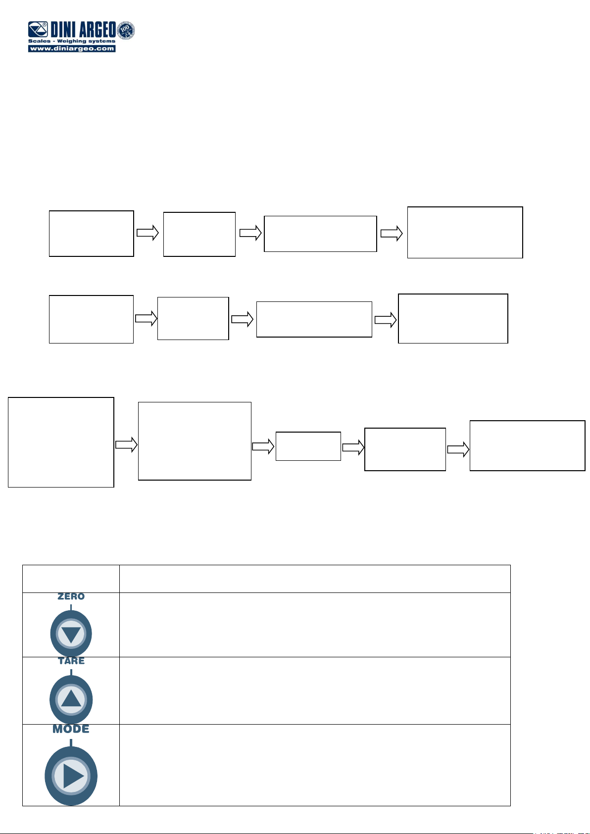
KEY
FUNCTION
Allows scrolling ahead through the programming steps.
Allows to scroll backwards through the programming steps.
Allows to quickly position on the first step of a menu.
“F.ModE”
on the display
“PrG.VEr”
on the display
PARTIAL SET-UP
MENU
(only user)
ENTER THE
PASSWORD
SUBSTITUTING THE
DISPLAYED VALUE
(*)
Press
ENTER
COMPLETE SET-UP
MENU
(technical personnel)
Press TARE/ZERO
during the
visualisation of the
“uSEr”
message
on the display
ACCESS
PASSWORD
ENABLED
ACCESS
PASSWORD
DISABLED
COMPLETE SET-UP
MENU
(technical personnel)
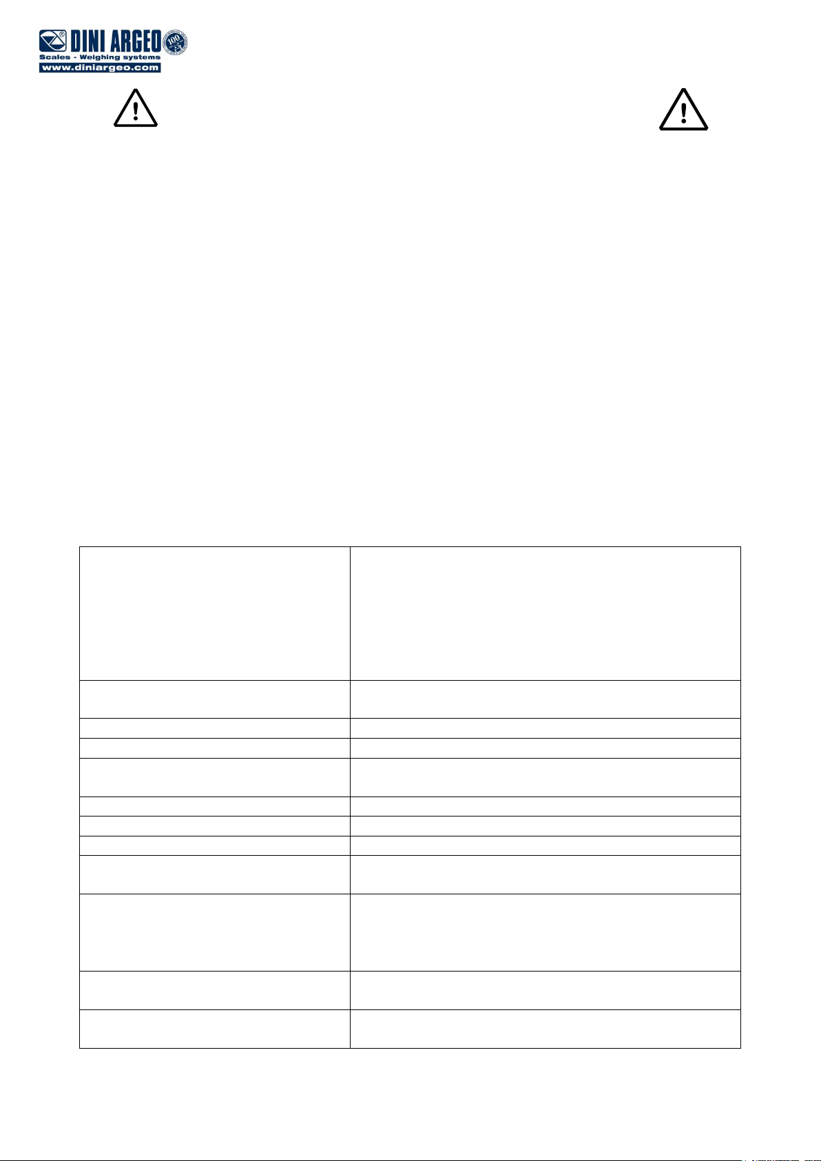
4 SETUP ENVIRONMENT
With "SETUP ENVIRONMENT" we intend a specific menu, where it’s possible to set all the functioning parameters of the
indicator.
To enter it, turn on the instrument and, while the firmware version is being displayed, press the TARE key for an
instant.
The indicator shows :
1)
or
2)
If you are in choice 2) and you want to access the complete set-up menu one should:
(*) If one has forgotten the password, one should communicate the displayed number to the manufacturer, who will supply a
valid password JUST FOR THAT SPECIFIC NUMBER.
In the SET-UP environment, the instrument keys take on the following functions:
DFWATEX2GDxxx 5 of 49
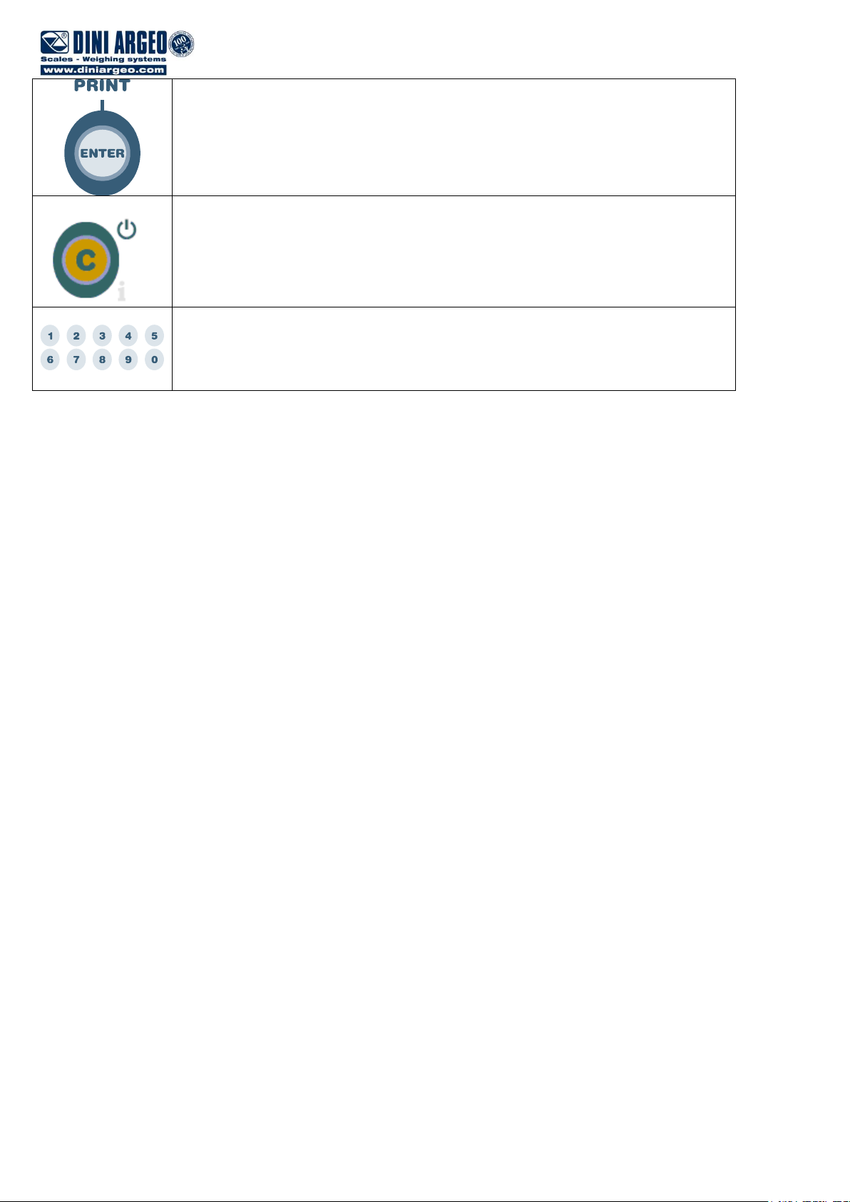
Allows to enter a step or confirm a parameter inside a step.
Allows to exit a step without confirming the possibly modified parameter and go to the
preceding level.
When entering a numeric value it quickly zeros the displayed value.
Allow to enter numeric values, from right to left.
The display indicates the abbreviation of the step whose meaning is described below.
In the parameter description and in the block diagram:
- The METRIC parameters are shown with the (*) symbol, and, with approved instrument, these may not be visible or
read only. See the explanation of the parameter for the details.
NOTE: The indicator is approved when the J1 jumper (CAL) of the motherboard is open
- The CONDITIONAL STEPS are shown with the (§) symbol, and are not displayed in specific conditions, shown in
the step description.
- The DEFAULT VALUES are shown with the (!) symbol placed next to the step and at the end of it.
TO EXIT THE SET-UP ENVIRONMENT, PRESS THE C KEY MANY TIMES UNTIL THE INDICATOR SHOWS “SAVE?”
IN THE DISPLAY: CONFIRM WITH ENTER/PRINT TO SAVE ANY CHANGES MADE OR PRESS ANOTHER KEY TO
NOT SAVE.
DFWATEX2GDxxx 6 of 49
F.Mode
DiAG. PrG.VEr
diV.int (§)
diSPLA
kEyb.
SEr
CtS.St.
bt.AdC
SETUP
ENVIRONMENT
inPutS (§)
StPn
rEACt (§) (!) ZEro, inSt, ALWAyS
SEtuP
deFAu (§)
(*) Ini.AL (§)
inPutS (§)
outPut (§)
SEriAL
(*) d.SALE (§)
tArE (§) (!) LoCK, unLoCK, Auto, diSAb
ConFiG
(!) no, yES
inP.01
inP.02
inP.03
inP.04
(!) nonE, ZEro, tArE,
ModE, EntEr, diS.kEy
out.01
out.02
out.03
out.04
FunC
no / nC
onStAt
(!) rEL.no, iSt.,
no.ISt
(!) no, nC
(!) StbL, drCt
AdC.uV (§)
AdC.Pnt (§)
Ser.nuM
inout
Alibi
hLd
StPG
(!) ntGS
Std
(!) G. t., 1St.2nd, in.out
MAStr (§)
ViSS
tot o
tot S
Coun
(!)MAnuAL, Auto
uM.APW
Wait.t
(!) G, kG, t, Lb
tYPE (§) (!) Ind.Ch, dEP.Ch
n.WEiGh
tot.Mod
outPut (§)
PW.AdC
= USER & TECH MENU’
= ONLY TECH MENU’
(*) = METROLOGICAL PARAMETER
(§) = CONDITIONED STEP
(!) = DEFAULT VALUE
LEGEND
PErC
ChECk (!) GroSS, nEt
(!) 00.1
Min.WGt (!) 000.000
MAX.WGt (!) 000.000
MAX.tot (!) 00
(!) no, yES
Fr2.tot (!) no, yES
Wait.St (!) 000
CPS.tAr (!) no, yES
(!) 05.0
FunCt.
En.SAVE AutoFF (!) diSAb, EnAb
(*) tiLt (!) diSAbL, EnAbLE
PWd.SEt (!) oFF, on
LCk.kEy (!) oFF, on
rEM.DSP (!) no, yES
rEPE (§)
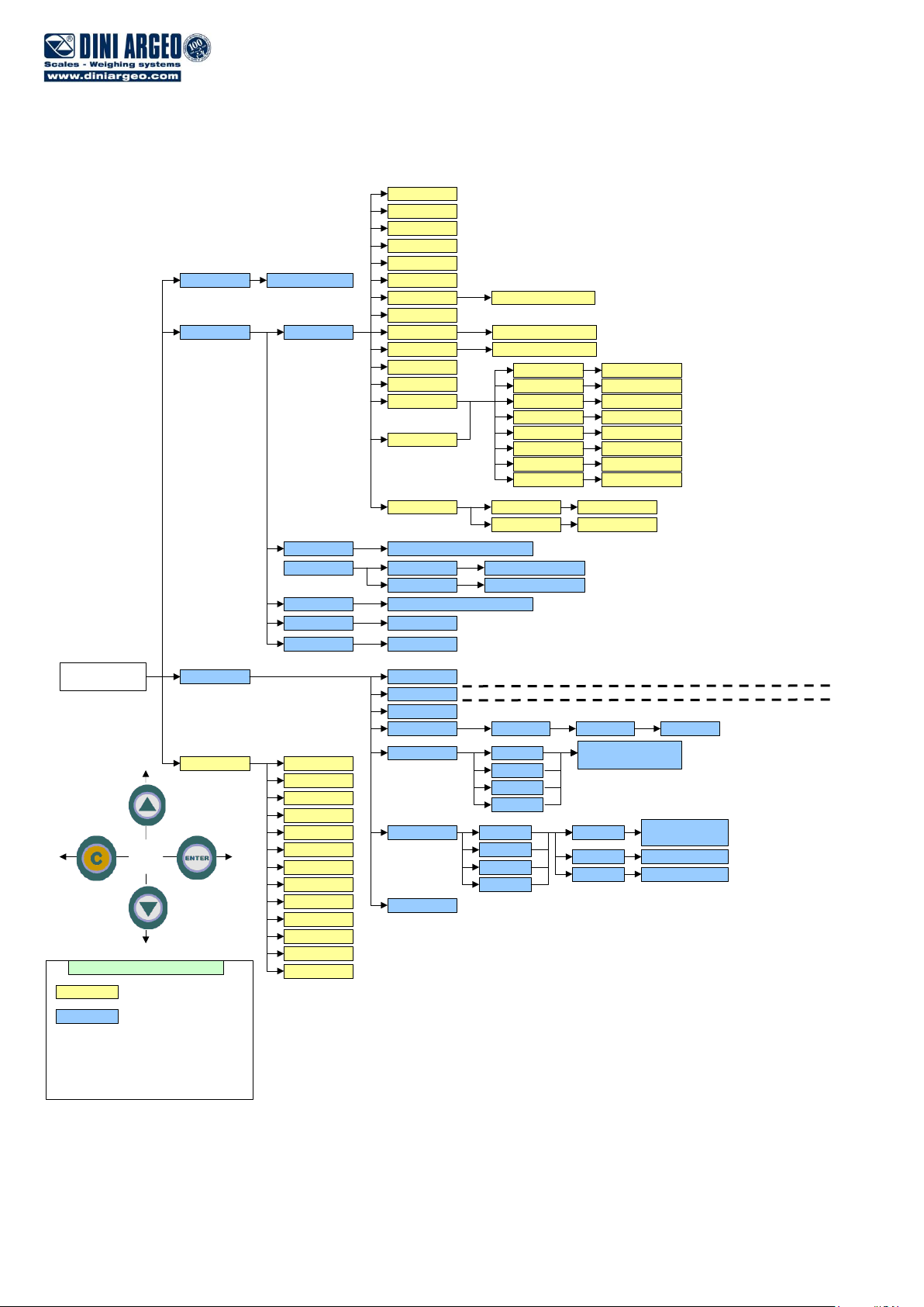
4.1 SET-UP ENVIRONMENT BLOCK DIAGRAM
The following diagram shows the structure of the indicator’s set-up environment; each step has been described in detail in
the “DESCRIPTION OF THE STEPS” section.
DFWATEX2GDxxx 7 of 49
DFWATEX2GDxxx 8 of 49
Stabil.
(!) FLt 3, FLt 0..3, doS.0..3,
h.r.0..7, dyn.0..3, SLW.0..3, hoLd
0...5, r.AdC 0...1, r.AdC d, r.AdC S
Calib (*)
Param.
ConFiG (§)
GrAV. (*)
Auto-0 (*)
0trACk (*)
diV.Stb. (*)
(!) EnAb, diSAb
(!) ½, ¼, 1, 2, no
(!) 2, 1...99
9,75001 … 9,84999
diV
dECi
u.M.
1, 2, 5, 10, 20, 50
G, Lb, t, kG
CALib.P
1, 2, 3, no
0.CALib (*)
rAnGE 1
rAnGE 2
tP 0
ddt 1
tp 1
ddt 2 (§)
n tP
EquAL (§)
tp 2 (§)
ddt 3 (§)
tp 3 (§)
nChan (*)(§) (!) Ch2 ... Ch4
rAnGE 3
VCEL Min, (!) MAX
AdJ.CAL (§)
Mod.Pnt
X
WEiGht tP X
MAn.CAL (§)
Mod.Pnt
X
WEiGht
PointS
XXXXXXXX
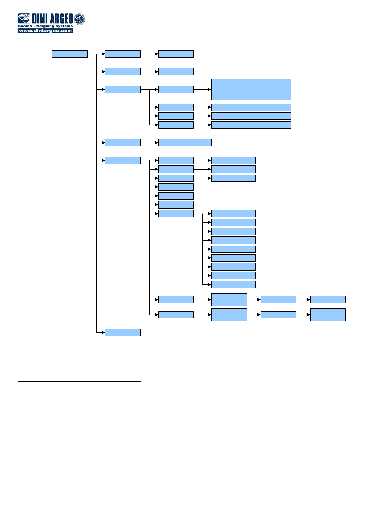
4.2 DESCRIPTION OF THE STEPS
(*) tYPE TYPE OF APPLICATION (§)
Here one selects the type of application: scale with a single channel or scale with dependent channels (eventually digitally
equalised).
ind.Ch. Instrument connected to 1 single-cell scale, or 1 scale with various cells equalised externally through the junction
box.
dEP.Ch. Instrument connected to 1 scale with 2, 3 or 4 dependent load cells (eventually equalised digitally through a
specific software procedure).
(!) ind.Ch
(*) In case of approved instrument the parameter is read only.
(§)The parameter is not displayed if the firmware is MASTER type.
DFWATEX2GDxxx 9 of 49

F.ModE SCALE FUNCTIONING
FunCt FUNCTIONING MODE
MAStr (M) Multiscale Repeater
rEPE (M) Single scale repeater
Std (S) Kg / lb conversion.
ntGS (S) Net weight / gross weight conversion.
StPG (S) Set point on gross weight
StPn (S) Set point on net weight
Inout (S) Input / output weigh.
ALibi (S) Alibi memory.
ChECk (S) +/- tolerance check.
PErC (S) Sample weight percentile
ViSS (S) Sensitivity times ten.
hLd (S) Freezing weight.
tot o (S) Horizontal totalizer.
tot S (S) Vertical totalizer.
Coun (S) Counting.
(!)ntGS if STANDARD firmware; (!) MAStr if MASTER firmware.
(S) The parameter is displayed if the firmware is STANDARD type.
(M) The parameter is displayed if the firmware is MASTER type.
For the functioning details and the relative parameters to be programmed, refer to section 14 “SELECTABLE
OPERATING MODES”, USER MAN.REF..
In case of a printer, it is necessary to execute the proper default printout in SEtuP >> SEriAL >> CoM.Prn >> Pr.ModE.
DFWATEX2GDxxx 10 of 49

rEACt REENABLING OF THE PRINTOUTS AND THE INDICATOR FUNCTIONS (§)
While using the indicator, it is possible to incur in the “no.0.unS” error shown on the display; this means that the printout
or the function which one wants to carry out must be renabled (in order to avoid accidental executions). It is possible to
set the reenabling in the following modes: “passage of the net weight by zero”, “weigh instability” or “always”.
ZEro passage of the net weight by zero
inSt instability
ALWAyS always
(!) ZEro
(§) The parameter is not displayed if the firmware is MASTER type.
En.SAVE ENERGY SAVING
AutoFF AUTO SWITCH-OFF
It is possible to enable the automatic switch off of the indicator (from 1 to 255 minutes), or disable it; the auto switch-off
starts working when, with an unloaded scale, the weight has not been moved or a key has been pressed during the set
time: the display shows the blinking “- oFF – “ message; then the indicator turns off.
diSAb auto switch-off disabled
EnAb auto switch-off enabled (one will be asked to enter the number of minutes after which the indicator must
turn off: enter a number from 1 to 255).
(!) diSAb
(*) tiLt TILT DEVICE ENABLING
If the indicator is fitted with the TILT device, in this step it’s possible to enable or disable its functioning.
EnAbLE enabled device
diSAbL disabled device
For further details see section 13.6, USER MAN.REF..
(!) diSAbL
(*) If the instrument is approved the parameter is read only.
tArE TARE TYPE SELECTION (§)
LoCk locked tare
unLoCk unlocked tare
diSAb disabled tare
Auto automatic unlocked tare
See the “TARE OPERATIONS” section for further functioning details, USER MAN. REF..
(!) LoCk
(§)The parameter is not displayed if the firmware is MASTER type.
PWd.SEt SET ACCESS PASSWORD
One selects whether to enable or disable the access password to the technical menu:
on password enabled
oFF password disabled
By selecting on, one can insert a password of up to 5 digits. When finished entering, press ENTER to confirm.
NOTE: The maximum enterable value is 65534.
(!) oFF
LCk.kEy KEYBOARD UNLOCKED/LOCKED (§)
One selects whether to enable or disable the keyboard locking in the weighing phase.
oFF keyboard lock disabled
on keyboard lock enabled
For further information see the section “KEYBOARD LOCK” (USER MAN.REF.).
(!) oFF
(§) The parameter is not displayed if the firmware is MASTER type.
DFWATEX2GDxxx 11 of 49

SEtuP SCALE CONFIGURATION
ConFiG METRIC CONFIGURATION
(*) nChAn SELECTION OF NR. OF INDICATOR CHANNELS (§)
2÷4 in SCALE WITH DEPENDENT CHANNELS functioning mode (“DEP.CH”)
(!) 2
(*) With approved instrument the parameter is read-only.
(§)The parameter is not displayed if the firmware is MASTER type. If the firmware is STANDARD type, the parameter is
not displayed in case of DEPENDENT CHANNELS functioning mode, tyPE parameter.
VCEL POWER SUPPLY VOLTAGE OF LOAD RECEIVERS
It is possible to select two voltage levels of the load cell power supply:
Min: power supply with voltage equal to 1,6V
Max: power supply with voltage equal to 3,2V
(!) MAX
PArAM METRIC PARAMETERS (§)
(§) The parameter is not displayed if the firmware is MASTER type.
(*) StAbiL FILTERING INTEGRATION
By pressing ENTER/PRINT one accesses the selection of the type and degree of filter intervention for the stability of
the weight indication:
FLt 0 – 3 filter for simple weighing
doS.0 – 3 filter for dosage
h.r.0 – 7 filter for high resolution
dyn.0 – 3 filter for a moving weight
SLW.0 – 3 filter for a rather unstable weight
hoLd 0 – 5 filter for animal weighing
r.AdC 0 – 1 filter for digital cells with fixed request interval
r.AdC d – S filter for digital cells with dynamic (d = fast, S = slow) request interval
The higher the filter value, and greater is its intervention relative to the type of filter used.
(!) FLt 3
(*) With approved instrument it is possible to select just the FLt 0–3, h.r.0, h.r.1, dyn.0, dyn.1, SLW.0, SLW.1
parameters.
(*) Auto-0 AUTOZERO AT THE START UP
By pressing ENTER/PRINT one chooses whether to enable (EnAb) or disable (diSAb) the automatic acquisition of
the gross zero upon start-up. By choosing EnAb, if upon start-up a detected weight is within +/- 10% of the capacity,
it is zeroed; if the weight is not within this tolerance, the non approved instrument’s display will show the present
weight after a few instants, while an approved instrument will continuously show “ZEro” on the display, until a weight
within tolerance is placed.
(!) EnAb
(*) With approved instrument the parameter is read-only.
(*) 0.trACk ZERO TRACKING
This menu allows setting the zero tracking, in other words, the compensation parameter of the scale’s thermal drift;
the set value corresponds to the number of divisions that is reset in the fixed time of 1 second.
tr. ½ +/- half division.
tr. ¼ +/- one fourth of a division
tr. 1 +/- one division.
tr. 2 +/- two divisions.
tr. no tracking disabled.
DFWATEX2GDxxx 12 of 49

(!) tr. ½
(*) With approved instrument it is possible to select just the tr. no, tr. ½, tr. ¼ parameters. .
(*)diV.Stb DIVISIONS BY STABILITY
In this step one enters the number of divisions by which the instrument detects the weight stability; the higher the
number of divisions, less is the sensitivity, and consequently the stability is more easily detected. The possible values
are 0 (weight always stable)…99.
(!) 2
(*) With approved instrument.
the parameter is read-only.
(*) GrAV. GRAVITY ZONE AND ZONE OF USE (§)
Through this step one selects the acceleration value of calibration and of use of the instrument:
Manual entry of the g value: one may manually enter the gravitational acceleration value; one must modify the 6
decimal digits of the gravitational acceleration.
In case one enters a wrong g value: the minimum decimal value is suggested (9,75001); a wrong value is any decimal
number that is not between 9,75001 and 9,84999 (inclusive).
(!) g = 9,80655
(*) With approved instrument the parameter is read-only.
(§) The parameter is not displayed if the firmware is MASTER type.
(*) CALib SCALE CALIBRATION (§)
See the section “SCALE CALIBRATION”
(*) With approved instrument the parameter is read-only.
(§)The parameter is not displayed if the firmware is MASTER type
(*) 0.CALib ZERO CALIBRATION (§)
See the section “SCALE CALIBRATION”.
(*) If the indicator is approved, the step is not displayed.
(§)The parameter is not displayed if the firmware is MASTER type.
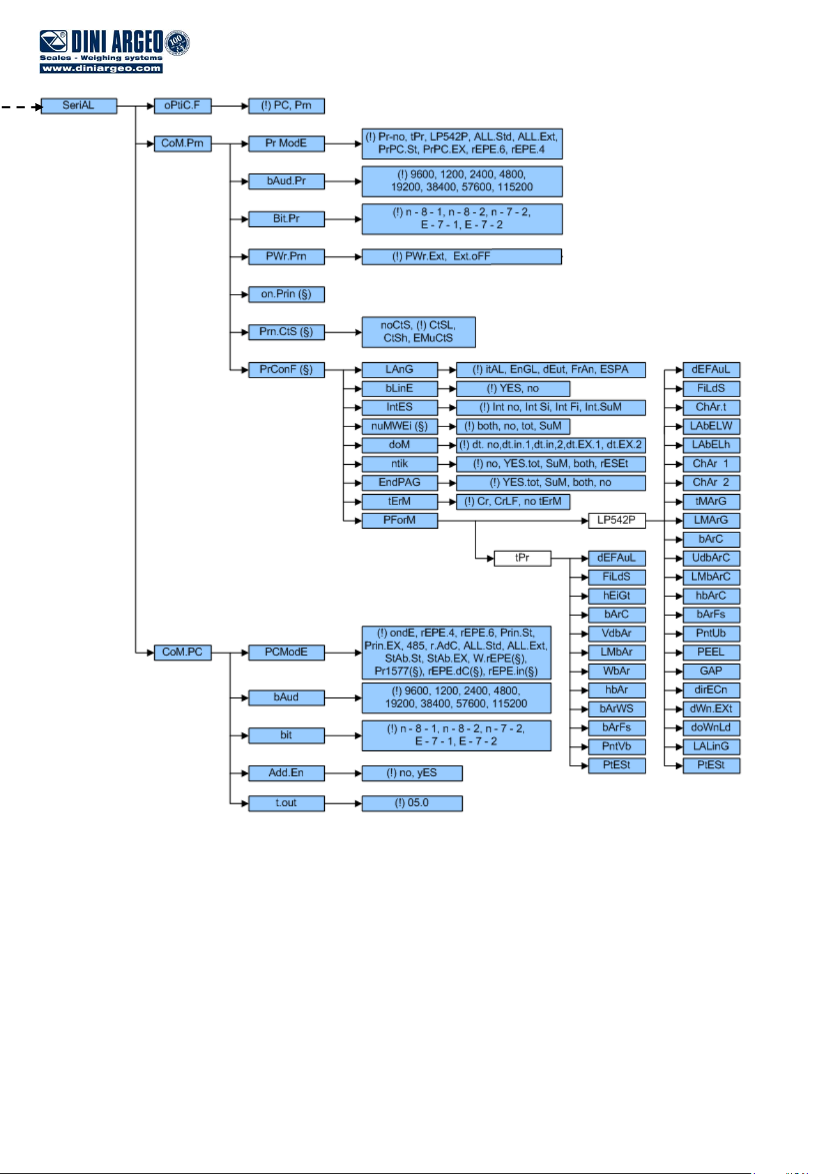
SEriAL SERIAL LINES, PRINTOUTS, ETC…
(TO BE SET ONLY WITH THE EXPANSION BOARD CONNECTED, PRESENT DEPENDING ON THE MODEL)
optiC.F SELECTION OF THE PORT TO BE USED FOR COMMUNICATING WITH THE PC
In this step it’s possible to select the use of the fiber optic serial port:
Pc: The fiber optics is used for the transmission configured in the pc port, SEtuP >> SEriAL >> CoM.Pc step
Prn: The fiber optics is used for the transmission configured in the printer port, SEtuP >> SEriAL >> CoM.Prn
step
(!) Pc
CoM.Prn PRINTER SERIAL LINE
Pr.ModE TRANSMISSION ON THE PRINTER SERIAL LINE
Pr- no transmission not enabled
tPr enables the printing with ASCII printer (for example DP190 or TPR).
LP542P enables to print with the LP542S labeller.
By confirming the “LP542P” or “tPr” parameter one is asked (through the “dEF.Pr?”
message) to set, for the selected printer, the default parameters in the steps of the printer
serial port (“bAud.Pr”, “bit.Pr”, “Prn.CtS”) and in the steps of printout configuration (see the
description of the “dEFAuL” step in the section “FORMATTING DATA AND LAYOUT”):
press ENTER/PRINT to confirm or C to cancel; then the “tESt?” message is displayed:
press ENTER/PRINT to execute the printout test or C to cancel (see the description of the
“PtESt” step in the section “FORMATTING DATA AND LAYOUT”).
ALL.Std continuous transmission with standard string.
ALL.EXt continuous transmission with extended string.
DFWATEX2GDxxx 13 of 49

PrPC.St transmission of the standard string upon the pressing of the ENTER/PRINT key.
PrPC.EX transmission of the extended string upon the pressing of the ENTER/PRINT key.
NOTE: The transmission of the standard or extended string upon the pressing of the PRINT key is confirmed by
“trAnSM” on the display. If the “TOTALIZER” mode (horizontal or vertical) is active, the transmission through the
key is carried out by pressing the MODE key.
rEPE.4 transmission to 4-digit remote display.
rEPE.6 transmission to 6-digit remote display.
MEMorY if enabled allows to store the weigh list on the EEPROM
(!) Pr-no
For the protocol and transmission mode specifications, see the sections “SERIAL PORT TRANSMISSION
MODES” and “TRANSMISSION PROTOCOLS”.
bAud.Pr SET BAUD RATE
By pressing the ENTER/PRINT key one accesses the selection of the data transmission speed (measured in
Baud = bit/second). The possible values are: 1200, 2400, 4800, 9600, 19200, 38400, 57600, 115200.
(!) 9600
bit.Pr SET PARITY, WORD, STOP BIT
By pressing the ENTER/PRINT key one accesses the selection of the available values: n-8-1, n-8-2, n-7-2, E-7-1,
E-7-2.
(!) n-8-1
PWr.Prn PRINTER MANAGEMENT
In this step one programmes the management of a printer (if connected):
PWr.EXt with instrument on, printer managed.
EXt.oFF printer managed; the start-up characters are sent to the printer, because the printer is
considered to be configured in the energy saving mode.
(!) PWr.EXt
on.Prin ENABLING OF PRINTER IN ENERGY SAVING MODE (§)
If in the preceding step the EXt.oFF management is set, by entering this step one turns on the printer in the
energy saving mode (the “onPri” message is blinking on the display).
To exit this step press any button. The enabling may be carried out quickly also during the weighing, by pressing
the ZERO key for a few seconds (except in the REPEATER functioning mode).
(§) The parameter is displayed if “EXt.oFF” has been selected in the “PWr.Prn” step.
Prn.CtS RTS/CTS STATUS CONFIGURATION (§)
Using the fibre optic transmission, it is possible to manage the CTS signal; device (like a printer) that is slow in
processing the data received, can interrupt the transmission by temporarily using this signal.
noCtS no signal
CtSL CTS active low (for LP542P, TPR, DP24 printers)
CtSh CTS active high (for DP190 printers)
EMuCtS emulation of the CTS signal: one is asked to enter the number of characters (nChrS), in 3 digits,
which will be transmitted to the printer upon each transmission; then one needs to enter the
waiting time in milliseconds (tiME), in 4 digits, between a transmission and another.
The TIME OUT of a printout is a minute, in other words, after a minute that the printout is
blocked, it is cancelled.
(!) noCtS
(§) The parameter is not displayed unless “tPr” or “LP542P” has been selected in the “Pr.ModE” step.
Pr.ConF CONFIGURATION OF THE PRINTOUTS (§)
See the section “PROGRAMMING THE PRINTOUTS” section for the description of all the menu’s parameters.
(§) The parameter and all its submenus are not displayed unless “tPr” or “LP542P” has been selected in the
“Pr.ModE” step.
DFWATEX2GDxxx 14 of 49

Received string
h
h
,
k
k
,
p
p
p
p
p
p
p
p
,
u
u
CR
LF
Position of the
character
00 01 02 03 04 05 06 07 08 09 10 11 12 13 14 15 16 17 18
CoM.PC PC SERIAL LINE
PCModE TRASMISSION ON THE PC SERIAL LINE
ondE transmission on external command PC).
rEPE.4 transmission to 4-digit remote display.
rEPE.6 transmission to 6-digit remote display.
Prin.St. transmission of standard string when the ENTER/PRINT key is pressed.
Prin.EX transmission of extended string when the ENTER/PRINT key is pressed.
NOTE: The transmission of the standard or extended string upon the pressing of the PRINT key is confirmed by
“trAnSM” on the display. If the “TOTALIZER” mode (horizontal or vertical) is active, the transmission through the
key is carried out by pressing the MODE key.
485 transmission with 485 protocol, by confirming with ENTER/PRINT, one is required to enter the
machine code (the message “Ad485” appears for an instant): enter a value between 0 and 98.
r.AdC transmission to digital cells (§) : by confirming with ENTER/PRINT, one is required to enter
the 485 address (the message “Ad485” appears for an instant), then one has to enter the offset
address (“Add.oFF” is displayed for an instant); in this transmission mode it is not possible to
communicate with the PC (for this purpose one has to set temporarily the 485 mode and the
instrument has to be in the setup environment).
(§) The parameter is not displayed if the firmware is MASTER type.
ALL.Std continuous transmission with standard string.
ALL.EXt continuous transmission with extended string.
StAb.St transmission with each weigh with standard string.
StAb.EX transmission with each weigh with extended string.
rEPE.dC transmission protocol. (§) The parameter is displayed only if one has selected the “rEPE” functioning
mode in the F.ModE >> FunCt step.
rEPE.in transmission protocol (§) It allows to manage the received string.
Pr1577 (§) reception of the “rEPE.6” string. (§) The parameter is displayed only if one has selected the “rEPE”
functioning mode in the F.ModE >> FunCt step.
W.rEPE (§) reception of string from remote scale. (§) The parameter is displayed only if one has selected the
“rEPE” functioning mode in the F.ModE >> FunCt step.
By confirming with ENTER/PRINT one is requested to set the following parameters for the
management of the remote scale:
tErM REMOTE SCALE TERMINATOR
In this step one enters the decimal ASCII code (up to 2 digits) of the terminator characters of the weight string (I.E.
13 for CR or 10 for LF or 0 for NULL).
(!) 10
WEi.PoS REMOTE SCALE WEIGHT POSITION
In this step one sets the position of the first character of the weight value, in the string transmitted by the remote
scale, knowing that the first character on the left of the string has the 00 position.
A possible character sign is also part of the weight value.
For example, if the received string is hh,kk,pppppppp,uu + CR + LF (see the section “TRANSMISSION
PROTOCOLS” for the description of the string),
one should set the 06 value.
It is possible to set up to 2 characters (from 0 to 39).
(!) 05
DFWATEX2GDxxx 15 of 49
 Loading...