

Dini Argeo 3590EXT series, 3590EKR series, 3590EXP series, CPWE series, CPWET series User Manual
USER MANUAL
WEIGHT INDICATOR
E-AF09: PROGRAM VERSION FOR DYNAMIC OR STATIC
AXLES WEIGHING WITH INPUT/OUTPUT FUNCTION
3590EKR, 3590EXP, 3590EXT, CPWE, CPWET series indicator
E-AF09_02_13.01_EN_U

3590EKR, 3590EXP, 3590EXT, CPWE, CPWET series indicator E-AF09_02_13.01_EN_U
1
INDEX
1. INTRODUCTION ................................................................................................................................................................... 4
2. MAIN TECHNICAL SPECIFICATIONS ................................................................................................................................. 5
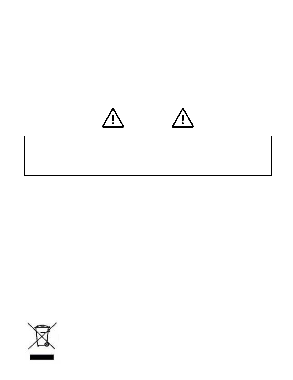
2.1 ACCESSORIES AVAILABLE ......................................................................................................................................... 6
2.2 SYMBOLS USED ........................................................................................................................................................... 6
3. INSTALLATION .................................................................................................................................................................... 7
3.1 CPWE DRILLING TEMPLATE, CASE AND DIMENSIONS ........................................................................................... 7
3.2 3590E CASE AND DIMENSIONS .................................................................................................................................. 8
3.2.1 ABS MODEL ........................................................................................................................................................ 8
3.2.2 STAINLESS STEEL MODEL ............................................................................................................................... 9
3.3 CPWET CASE AND DIMENSIONS.............................................................................................................................. 10
3.4 POWER SUPPLY ......................................................................................................................................................... 11
3.5 START UP .................................................................................................................................................................... 11
3.6 TURNING OFF THE INSTRUMENT ............................................................................................................................ 11
3.7 TURNING ON PRINTER IN ENERGY SAVING MODE ............................................................................................... 12
4. FRONT PANEL KEYS ........................................................................................................................................................ 12
4.1 FUNCTION OF THE KEYS .......................................................................................................................................... 13
4.2 "2ndF" KEY: SECOND FUNCTION OF THE KEYS ..................................................................................................... 15
4.3 ENTERING ALPHANUMERIC TEXT ........................................................................................................................... 15
4.4 DISABLING THE KEYBOARD ..................................................................................................................................... 16
4.5 HELP MENU ................................................................................................................................................................ 16
4.6 INDICATOR CONNECTED TO REMOTE KEYBOARD ............................................................................................... 16
4.7 REMOTE CONTROL.................................................................................................................................................... 17
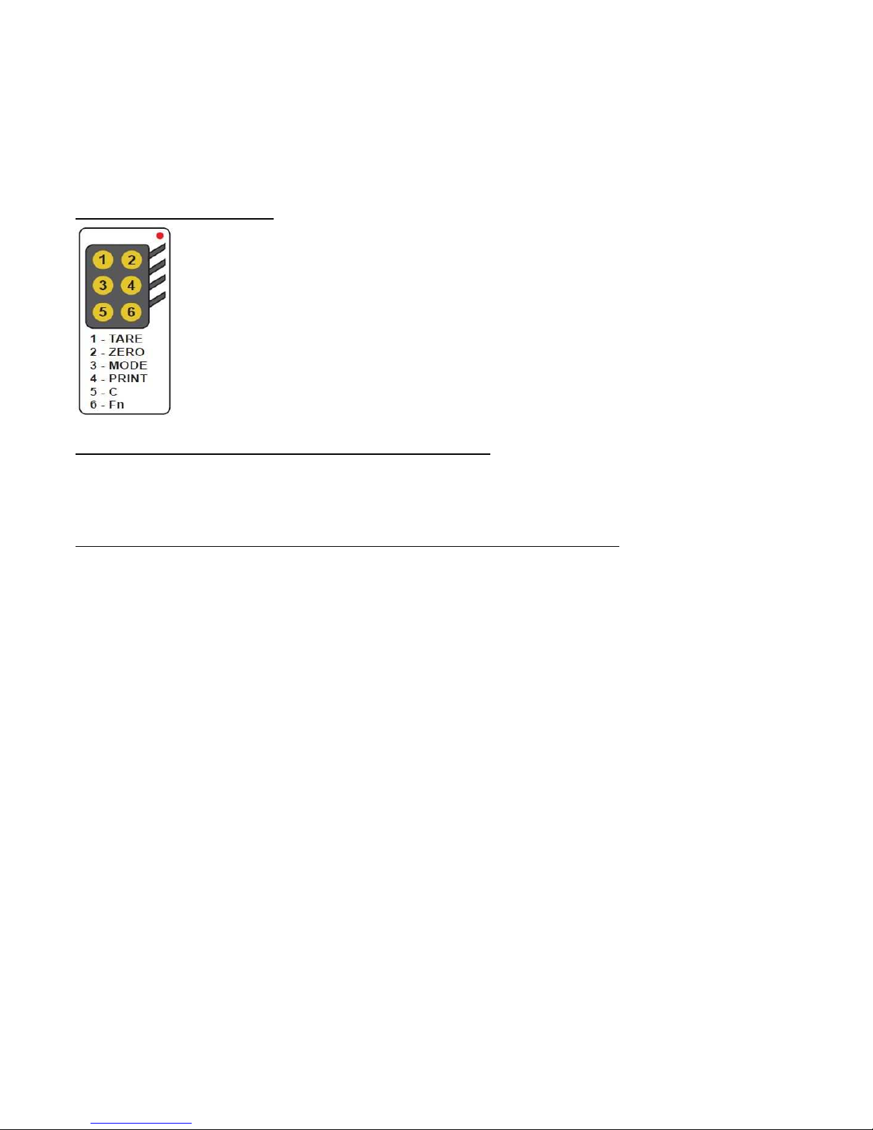
4.7.1 “19-KEY” INFRARED REMOTE CONTROL ...................................................................................................... 17
4.7.2 “6-KEY” RADIO REMOTE CONTROL ............................................................................................................... 18
5. DISPLAY FUNCTIONS ....................................................................................................................................................... 19
5.1 WEIGHT ZOOM (available only on CPWE and CPWET models) ................................................................................ 20
5.2 STATUS INDICATORS ................................................................................................................................................ 20
5.3 BATTERY LEVEL INDICATION ................................................................................................................................... 21
5.4 DISPLAYED DATA ....................................................................................................................................................... 22
5.4.1 LCD DISPLAY CUSTOMIZATION (ONLY FOR 3590E INDICATORS) ............................................................. 23
5.5 MESSAGES OF THE INSTRUMENT ........................................................................................................................... 24
5.5.1 INSIDE THE SET-UP OR MENU OR AT START-UP ........................................................................................ 24
5.5.2 IN WEIGHING.................................................................................................................................................... 25
6. SCALE ZERO FUNCTION .................................................................................................................................................. 25
7. TARE FUNCTIONS ............................................................................................................................................................. 25
7.1 MANUAL PRESET TARE TO BE SUBTRACTED TO THE TOTAL ACCUMULATED WEIGHT .................................. 25
7.2 CALCULATED MANUAL TARE ................................................................................................................................... 26
7.3 TARE CANCELLATION ............................................................................................................................................... 26
7.4 LOCKED/UNLOCKED TARE ....................................................................................................................................... 26
7.5 LIMITATION OF THE TARE FUNCTIONS ................................................................................................................... 26
7.6 TARE EXECUTION MODE OR DISABLING OF THE TARE ....................................................................................... 26
7.7 ENTERING OF A PRESET TARE IN A VEHICLE IN THE DATABASE. ...................................................................... 26
8. MULTIRANGE AND MULTIDIVISION FUNCTION ............................................................................................................. 27
9. DISPLAY OF METRIC DATA (inFO) .................................................................................................................................. 27
10. FILLING IN THE INPUT TEXT .......................................................................................................................................... 27
11. DATABASE....................................................................................................................................................................... 28
11.1 CUSTOMER DATABASE ........................................................................................................................................... 28
11.1.1 ENTRY ............................................................................................................................................................ 28

3590EKR, 3590EXP, 3590EXT, CPWE, CPWET series indicator E-AF09_02_13.01_EN_U
2
11.1.2 MODIFICATION ............................................................................................................................................... 29
11.1.3 CANCELLATION ............................................................................................................................................. 29
11.1.4 PRINTING ....................................................................................................................................................... 29
11.1.5 SELECTION / DESELECTION ........................................................................................................................ 30
11.1.6 ENTRY, MODIFICATION AND QUICK SELECTION OF CUSTOMER 000 .................................................... 31
11.1.7 ALPHABETICAL RESEARCH ......................................................................................................................... 31
11.1.8 HELP ............................................................................................................................................................... 31
11.2 MATERIALS ............................................................................................................................................................... 31
11.2.1 ENTRY ............................................................................................................................................................ 31
11.2.2 MODIFICATION ............................................................................................................................................... 32
11.2.3 CANCELLATION ............................................................................................................................................. 32
11.2.4 PRINTING ....................................................................................................................................................... 32
11.2.5 SELECTION / DESELECTION ........................................................................................................................ 33
11.2.6 ENTRY, MODIFICATION AND QUICK SELECTION OF MATERIAL 000 ....................................................... 33
11.2.7 ALPHABETICAL RESEARCH ......................................................................................................................... 34
11.2.8 HELP ............................................................................................................................................................... 34
11.3 VEHICLES .................................................................................................................................................................. 34
11.3.1 ENTRY ............................................................................................................................................................ 34
11.3.2 MODIFICATION ............................................................................................................................................... 35
11.3.3 CANCELLATION ............................................................................................................................................. 35
11.3.4 PRINTING ....................................................................................................................................................... 35
11.3.5 SELECTION / DESELECTION ........................................................................................................................ 36
11.3.6 ENTRY, MODIFICATION AND QUICK SELECTION OF VEIHCLE 000 ......................................................... 36
11.3.7 ALPHABETICAL RESEARCH ......................................................................................................................... 37
11.3.8 HELP ............................................................................................................................................................... 37
12. DATABASE ACCESS PASSWORD ................................................................................................................................. 37
13. WEIGHING PROCEDURES .............................................................................................................................................. 37
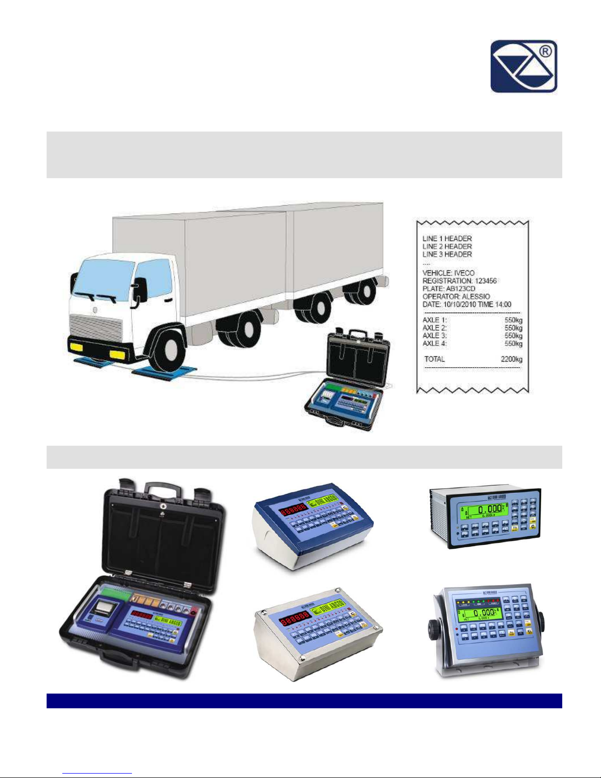
13.1 GENERAL DESCRIPTION OF THE SYSTEM ........................................................................................................... 37
13.2 SIMPLE AXLES WEIGHING ...................................................................................................................................... 38
13.2.1 MANUAL AXLE WEIGHING ............................................................................................................................ 38
13.2.1.1 CONFIGURATION ............................................................................................................................. 38
13.2.1.2 WEIGHING PROCEDURE ................................................................................................................. 38
13.2.2 AUTOMATIC STATIC AXLE WEIGHING ........................................................................................................ 40
13.2.2.1 CONFIGURATION ............................................................................................................................. 40
13.2.2.2 WEIGHING PROCEDURE ................................................................................................................. 40
13.2.3 AUTOMATIC DYNAMIC AXLE WEIGHING ..................................................................................................... 43
13.2.3.1 CONFIGURATION ............................................................................................................................. 43
13.2.3.2 WEIGHING PROCEDURE ................................................................................................................. 43
13.3 INPUT-OUTPUT AXLE WEIGHING ........................................................................................................................... 46
13.3.1 MANUAL AXLE WEIGHING ............................................................................................................................ 46
13.3.1.1 CONFIGURATION ............................................................................................................................. 46
13.3.1.2 INPUT WEIGHING PROCEDURE ..................................................................................................... 46
13.3.1.3 STARTING OUTPUT WEIGHING THROUGH ID CODE ................................................................... 48
13.3.1.4 STARTING OUTPUT WEIGHING THROUGH LICENSE PLATE ....................................................... 49
13.3.1.5 OUTPUT WEIGHING PROCEDURE ................................................................................................. 49
13.3.2 AUTOMATIC STATIC AXLE WEIGHING ........................................................................................................ 51
13.3.2.1 CONFIGURATION ............................................................................................................................. 51
13.3.2.2 INPUT WEIGHING PROCEDURE ..................................................................................................... 51
13.3.2.3 STARTING OUTPUT WEIGHING THROUGH ID CODE ................................................................... 54
13.3.2.4 STARTING OUTPUT WEIGHING THROUGH LICENSE PLATE ....................................................... 54
13.3.2.5 OUTPUT WEIGHING PROCEDURE ................................................................................................. 55
13.3.3 AUTOMATIC DYNAMIC AXLE WEIGHING ..................................................................................................... 57
13.3.3.1 CONFIGURATION ............................................................................................................................. 57
13.3.3.2 INPUT WEIGHING PROCEDURE ..................................................................................................... 57
13.3.3.3 STARTING OUTPUT WEIGHING THROUGH ID CODE ................................................................... 60

3590EKR, 3590EXP, 3590EXT, CPWE, CPWET series indicator E-AF09_02_13.01_EN_U
3
13.3.3.4 STARTING OUTPUT WEIGHING THROUGH LICENSE PLATE ....................................................... 60
13.3.3.5 OUTPUT WEIGHING PROCEDURE ................................................................................................. 61
13.3.3.6 SELECTING INPUT OR OUTPUT BEFORE OR AFTER HAVING ACQUIRED THE AXLES ............ 63
13.3.4 NOTES ON THE INPUT WEIGHING ............................................................................................................... 63
13.3.5 NOTES ON THE OUTPUT WEIGH ................................................................................................................. 64
13.3.6 DETERMINATION OF THE TRUCK’S NET WEIGHT BY SUBTRACTING THE PRESET TARE ................... 64
13.3.7 DELETING ALL THE INPUT MEMORY STORAGES ...................................................................................... 65
13.4 FUNCTIONS OF THE AUTOMATIC AXLE WEIGHING CYCLE (STATIC OR DYNAMIC) ........................................ 65
13.4.1 CANCELLING OF THE CYCLE ....................................................................................................................... 65
13.4.2 ERRORS ON THE AUTOMATIC AXLES WEIGHT ACQUISITION ................................................................. 66
13.4.2.1 ERROR ON THE DYNAMIC AXLES WEIGHT ACQUISITION ........................................................... 66
13.4.2.2 ERROR ON THE STATIC AXLES WEIGHT ACQUISITION .............................................................. 66
13.4.3 RESET OF THE ERROR AXLE IN THE DYNAMIC CYCLE ............................................................................ 67
13.4.4 MANAGING AN INPUT FOR THE CYCLE START/END ................................................................................. 67
13.4.5 MANAGING THE OUTPUTS ........................................................................................................................... 67
13.4.6 PAUSE AXLES CAPTURING .......................................................................................................................... 67
13.5 SETTING AXLES SO THAT THESE ARE NOT TOTALISED .................................................................................... 68
13.6 ADDITIONAL TARE FUNCTION ................................................................................................................................ 68
13.7 REENABLING THE WEIGH ....................................................................................................................................... 69
13.8 WEIGHT THRESOLDS FOR EXECUTING THE WEIGH ........................................................................................... 69
13.9 VISUALISATION AND CLEARING OF THE ACCUMULATED TOTALS ................................................................... 69
13.10 PROGRESSIVES ..................................................................................................................................................... 70
13.10.1 PROGRESSIVE DIGITS ................................................................................................................................ 70
13.10.2 TICKET PROGRESSIVE ............................................................................................................................... 70
13.10.3 LOT PROGRESSIVE ..................................................................................................................................... 70
14. PRINTOUTS ...................................................................................................................................................................... 71
14.1 LINKING OF THE FORMATS TO THE PRINT FUNCTIONS ..................................................................................... 74
14.1.1 QUICK LINKING OF THE FORMATS ............................................................................................................. 75
14.2 NUMBER OF TICKET COPIES .................................................................................................................................. 75
14.3 REPETITION OF THE LAST EXECUTED PRINTOUT .............................................................................................. 76
14.4 DEFAULT PRINTING FORMATS............................................................................................................................... 76
15. OTHER FUNCTIONS ........................................................................................................................................................ 76
15.1 DIAGNOSTIC PERIPHERALS ................................................................................................................................... 76
15.2 COM DATA DIAGNOSTIC ......................................................................................................................................... 76
15.3 CALCULATOR ........................................................................................................................................................... 77
15.3.1 HELP FUNCTION ............................................................................................................................................ 77
15.4 DISPLAY OF NET WEIGHT WITH SENSITIVITY X 10 (for testing use during calibration) ........................................ 77
15.5 SETTING DATE / TIME .............................................................................................................................................. 77
15.6 SET-POINT FUNCTION ............................................................................................................................................. 78
DECLARATION OF CONFORMITY ....................................................................................................................................... 82
WARRANTY ........................................................................................................................................................................... 82
3590EKR, 3590EXP, 3590EXT, CPWE, CPWET series indicator E-AF09_02_13.01_EN_U
4
1. INTRODUCTION
This manual was created to help you install and learn all about the functional possibilities of the purchased indicator.
The instrument is suitable for use in various weighing environments.
Not only does it have all the normal features of high-precision scales, but it also gives you the possibility to work in specific
environments due to the functioning modes contained in the software implemented in the FLASH MEMORY on the internal
board; This makes the instrument extremely flexible and it can be used in many different industrial applications linked to
weighing. The double numerical and interactive alphanumerical display, the alphanumerical and function keyboard, allow the
operator an easy and immediate use and provide the microcontroller with DATA ENTRY functions in addition to the normal
weighing functions. The input/output allows the instrument to control various external devices, to receive external commands,
control a printer and communicate with a personal computer or to be inserted in a network of weight indicators controlled by a
PC.
WARNING
Please note that this instrument is covered by a warranty and MUST NOT BE OPENED BY THE USER for any reason
whatsoever. Any attempt to repair or modify the unit exposes the user to the risk of electric shock and will invalidate the entire
warranty.
If any problems are found in the unit or with the system in which it is used, the fact must be communicated to the
manufacturer or the dealer from whom it was purchased.
In any case, DISCONNECT THE POWER SUPPLY before taking any action.
With the 6V rechargeable battery version, it has to be completely
recharged
(12 hours) in the first installation of the
instrument; we RECOMMEND disconnecting the battery if the instrument is not going to be used for more than 30
days. In order to avoid the deterioration of the rechargeable battery:
- In standard conditions, never leave the battery partially or completely uncharged; at least once a week recharge it
completely.
- In case the instrument is not used for a long period, one needs to
1. completely recharge the battery before the system is switched off for the last time;
2. recharge completely every 3 months.
Do not pour liquids on the weight indicator.
Do not use solvents to clean the weight indicator.
Do not expose the instrument to direct sunlight nor place it near heat sources.
Place or anchor the weight indicator and platform on a non-vibrating base.
All the connections of the indicator have to be made respecting
the rules applicable in the zone and in the installing environment.
Read carefully and apply what is described in the section 3.
Do not install in any area where there is a risk of explosion.
The crossed-out wheeled bin on the product means that at the product end of life, it must be taken to
separate collection or to the reseller when a new equivalent type of equipment is purchased. The
adequate differentiated refuse collection in having the product recycled, helps to avoid possible negative
effects on the environment and health and supports the recycling of the materials of which the equipment
is made. The unlawful disposal of the product by the user will entail fines foreseen by the current
regulations.

3590EKR, 3590EXP, 3590EXT, CPWE, CPWET series indicator E-AF09_02_13.01_EN_U
5
2. MAIN TECHNICAL SPECIFICATIONS
POWER SUPPLY
3590E
:
- 12 Vdc ( 8 ÷ 36 Vdc in the IO versions), with internal 100 ÷ 240 Vac (50÷60 Hz)
/ 12 Vdc adapter.
- 6 Vdc from rechargeable built-in battery, fitted depending on the model.
CPWE:
- 8 ÷ 2436 Vdc
- 6 Vdc from external rechargeable battery (upon request).
CPWET:
12 Vdc with external 100 ÷ 240 Vac (50÷60 Hz) / 12 Vdc adapter.
6 Vdc from external rechargeable battery (upon request).
MAXIMUM POWER
16 VA.
OPERATING TEMPERATURE
From
-
10 to +40 °C.
CONVERTER
24 bit Sigma Delta.
CONVERSION SPEED
200 conv./sec with automatic selection.
RANGE OF INPUT SIGNAL
0,6 mV/V
- 3,2 mV/V.
MINIMUM VOLTAGE PER DIVISION
0.3 µV (approved instrument); 0.03 µV (non-approved instrument).
AUTOMATIC ZERO DETECTION
Only in gross mode
, programmable at +/
- ¼, ½, 1, 2 divisions.
ZERO RANGE
Configurable up t
o +/- 50%
of max load capacity.
AUTO ZERO AT START
-UP
Configurable up to +/
- 50% of max load capacity.
LOAD CELL POWER SUPPLY
5Vdc ± 5%, 120mA
(max 8 350
-
Ohm cells).
LOAD CELL CONNECTIONS
6 wires with Remote Sense.
DISPLAY DIVISIONS
10000e, 3 x 3000e f
or legal for trade weighing, expandable up to 800.000 for
internal use (with minimum signal coming from the 1,6 mV/V cell).
DISPLAYS
3590E:
- Red, high-luminosity LED indicators, with six digits (h 13 mm).
- Back lit graphic 160x32 dot LCD.
CPWE: Back lit graphic 160x32 dot LCD.
DATABASE/MEMORY
Database of 500 customers
(3
descriptions of 20 characters).
Database of 500 products (2 descriptions of 20 characters).
Database of 500 vehicles (description of 20 characters, plate of 10 characters,
linked tare).
SIGNALS
3590E:
16 status LEDs. Graphic icons on LCD display.
CPWE: Graphic icons on LCD display.
CPWET: 3-way control light. Graphic icons on LCD display
KEYBOARD
I
mpermeable polycarbonate keyboard with 24 multifunction
(IP65 protection
degree), with membrane keys with audible and tactile feedback.
PARAMETER SETUP
Calibration and linearity (up to 8 points), fully digital and programmable from the
keyboard or from PC with Dinitools ™.
CLOCK/DATE
Fitted
, with buffer RAM.
SERIAL OUTPUTS
- 2 input/output RS232 ports on terminal board/ amp connector.
- 1 input/output RS485 port on terminal board or RS232 on amp connector.
- Management of PC keyboard or barcode reader
INPUTS AND OUTPUTS
3590EXP
,
3590EXT
and
CPWET
:
- 2 optoisolated inputs (optoisolated photo couplers), 12Vdc – 24Vdc, 20mA max
- 4 outputs (optoisolated photomosfets), 48Vac / 0.15A, 60Vdc / 0.15A, 10 Ω
max.
3590EXT (in IO version) and CPWE:
- 8 inputs (optoisolated photo couplers), 12Vdc – 24Vdc, 20mA max.
- 16 outputs (optoisolated photomosfets), 48Vac / 0.15A, 60Vdc / 0.15A.
3590EKR, 3590EXP, 3590EXT, CPWE, CPWET series indicator E-AF09_02_13.01_EN_U
6
ANALOGUE OUTPUT (Option
available on the 3590EXT in IO version
and CPWE version)
- 16-bit analogue output configurab
le from keyboard (full
-
scale value; zero scale
value and minimum value) from 0 to 10 Vdc, from 0 to 20mA or from 4 to 20mA;
the maximum resistance applicable on the output current is 350 Ohm and the
minimum resistance applicable on the output voltage is 10 kohm.
2.1 ACCESSORIES AVAILABLE
On the indicator is possible to implement internal and external modules used to increase interfacing possibilities.
For example, the number of usable outputs, various types of printers, in order to have a report of the weighs made, or giant
display in order to better see the weigh operations. Also, one can connect a PC in order to simply program the instrument
through Dinitools™, or in order to have a complete management of the weighs.
Contact the reseller for the list of the available hardware and software accessories.
2.2 SYMBOLS USED
Below are the symbols or texts used in the manual to recall the reader’s attention and on the instrument to recall the
user’s attention
ATTENTION!
Only qualified personnel must perform this operation
ATTENTION!
This is referred to working on energized lines: only qualified personnel must require or perform
this operation.
CE CONFORMITY
IDENTIFIES THE CLASS OF PRECISION.
“TECH.MAN.REF.”
It means that an advanced function is being described (therefore for the technical personnel)
which will be further explained in the corresponding technical manual.
THE INSTRUMENT’S DANGEROUS VOLTAGE PARTS AND THE PARTS THE USER CAN ACCESS HAVE BEEN
ELECTRICALLY INSULATED.
3590EKR, 3590EXP, 3590EXT, CPWE, CPWET series indicator E-AF09_02_13.01_EN_U
7
Figure 1
3. INSTALLATION
3.1 CPWE DRILLING TEMPLATE, CASE AND DIMENSIONS
The weight indicator has an anodized aluminium case, whose external dimensions are shown in the figure 1.
It should be mounted on a panel board respecting the safety norms.
DRILLING TEMPLATE DIMENSION: 187,5mm x 91,5mm
3590EKR, 3590EXP, 3590EXT, CPWE, CPWET series indicator E-AF09_02_13.01_EN_U
8
Figure 2
– Measurements and dimensions in mm
1) RJ45 connector
2) Fixing for shelf or column mounting
3/5) Available for load cells / serial lines / inputs / outputs.
4) Power supply input.
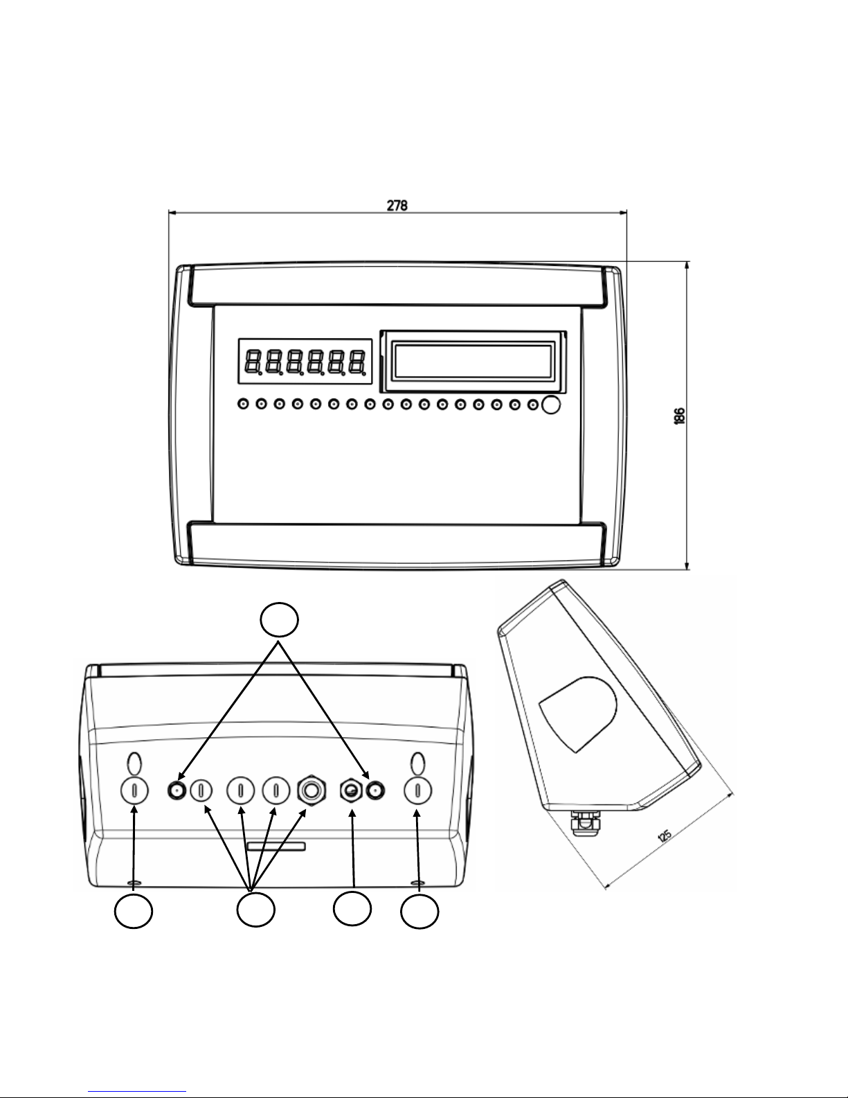
3.2 3590E CASE AND DIMENSIONS
3.2.1 ABS MODEL
The indicator has an IP65 ABS case, whose external dimensions are shown in the Figure 2. It can be simply put on a table
or fixed to a shelf; or on a column, available on request.
NOTE: If the identification plate is supplied separately (therefore not attached to the indicator), it is advisable to
attach it to the indicator, in order to be able to identify the instrument.
1
2
3
4
5
3590EKR, 3590EXP, 3590EXT, CPWE, CPWET series indicator E-AF09_02_13.01_EN_U
9
Figure 3
– Measurements and dimensions in mm
1) RJ45 connector
2) Fixing for shelf or column mounting
3) Available for load cells / serial lines / inputs / outputs.
4) Power supply input.
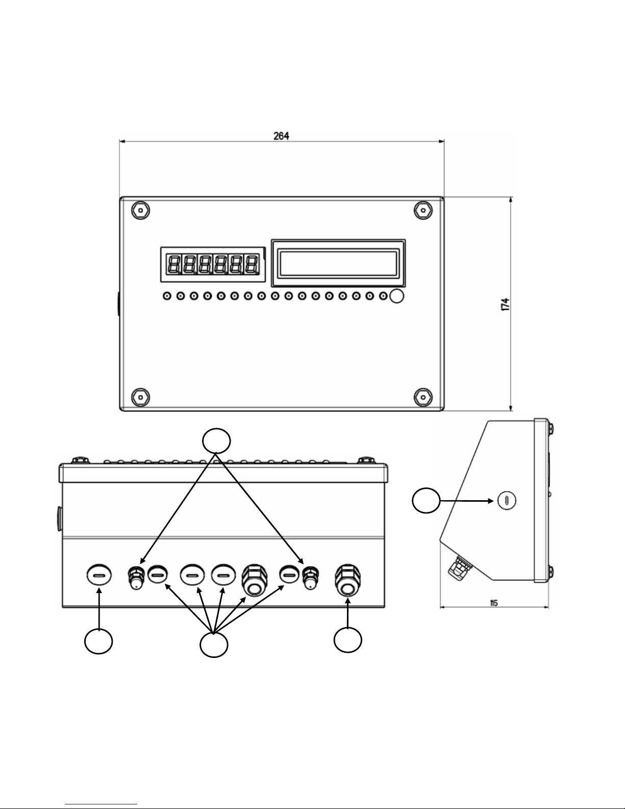
3.2.2 STAINLESS STEEL MODEL
The indicator has a STAINLESS STEEL case, whose external dimensions are shown in the Figure 3. It can be simply put on
a table or fixed to a shelf; or on a column, available on request.
NOTE: If the identification plate is supplied separately (therefore not attached to the indicator), it is advisable to
attach it to the indicator, in order to be able to identify the instrument.
1
2
3
4
3
3590EKR, 3590EXP, 3590EXT, CPWE, CPWET series indicator E-AF09_02_13.01_EN_U
10
Figure 4
– Measurements and dimensions in mm
1/2) Available for load cells / serial lines / inputs / outputs
3) Power supply input.
4) RJ45 connector
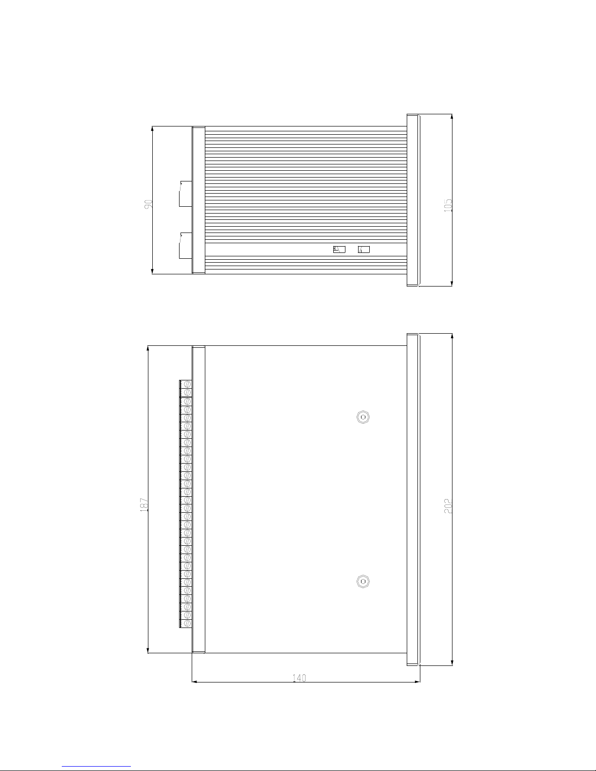
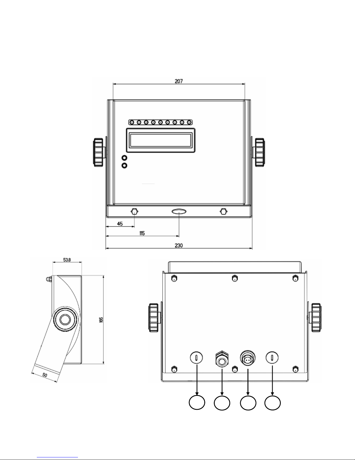
3.3 CPWET CASE AND DIMENSIONS
The weight indicator has a STAINLESS STEEL case, whose external dimensions are shown in the figure 4. The instrument
may be installed on the wall.
NOTE: If the identification plate is supplied separately (therefore not attached to the indicator), it is advisable to
attach it to the indicator, in order to be able to identify the instrument.
1
2
3
4

3590EKR, 3590EXP, 3590EXT, CPWE, CPWET series indicator E-AF09_02_13.01_EN_U
11
3.4 POWER SUPPLY
- The 3590E indicator is powered with 12Vdc voltage ( 8 ÷ 36 Vdc in the IO version), through an internal adapter which
converts the 100 ÷ 240Vac, 50÷60Hz mains voltage and 6 Vdc, from the built-in battery (fitted, depending on the model).
TO POWER the instrument through the 240 Vac mains, or TO RECHARGE the battery, insert the plug and the adapter to the
240 Vac mains socket.
- The CPWE indicator is powered with 8÷36 Vdc voltage or with 6 Vdc external battery (upon request).
- The CPWET indicator is powered with 12 Vdc voltage or with 6 Vdc external battery (upon request).
To connect it to the power mains, the safety regulations must be observed, including the use of a "clean" line without
disturbances or interference caused by other electronic equipment.
Version with rechargeable battery: the battery inside the indicator, lasts about 25 hours (without the expansion board, with
1-cell platform) and it needs a recharging time of about 12 hours.
BATTERY FEATURES
Material LEAD
Power 4,5 Ah
Voltage 6 V
THE BATTERY MUST BE SUPPLIED DIRECTLY FROM THE MANUFACTURER.
NOTE: it is advisable to completely recharge it (12 hours) in the first installation of the instrument; we RECOMMEND
disconnecting the battery if the instrument is not going to be used for more than 30 days.
Do not connect other equipment to the same socket as the one that the adapter is in.
Do not step on or crush the power supply cable
3.5 START UP
TO TURN ON the 3590E or the CPWET press the C key until the display turns on; then release.
The CPWE instead is automatically turned on as soon as it is powered.
The display shows:
- Initially a welcome message (settable in the TECHNICAL SET-UP, << LoGo >> StEP, TECH.MAN.REF) while the
instrument carries out a series of checking and preheating self tests.
- E-AF09 - XX name of the installed software, in which XX identifies the software language.
XX.YY is the software version installed.
- “EXECUTION AUTOZERO”
The instrument carries out the "autozero at start-up” function: if a weight is detected within the percentile set in the <<
Auto-0 >> step (TECH.MAN.REF.), it is cleared; if the weight is not within this tolerance:
- with a non approved instrument, the display shows the weight after a few instants,
- with an approved instrument, the message “EXECUTION AUTOZERO” appears continuously on the display, until the
weight is within tolerance.
The autozero function at start-up can be disabled in the set-up environment (only with a non approved instrument), see the
<<Auto-0>> parameter.
By pressing the 2ndF key for an instant while the version is shown in the display, the indicator will show in this order:
XX.YY in which XX indicates the instrument type, YY indicates the metrological software version.
XX.YY.ZZ is the installed software version.
HH is the installed hardware version (08).
LEGAL FOR TRADE or HIGH RESOLUTION if the instrument is APPROVED or UNAPPROVED, respectively.
9.XXXXX is the g gravity value (only with APPROVED instrument).
3.6 TURNING OFF THE INSTRUMENT
TO TURN OFF the 3590E/CPWET or TO RESTART the CPWE keep the C key pressed until the “- OFF -“ message appears
on the LED display and “ *** POWER OFF *** ” on the LCD display.
TO TURN OFF the CPWE remove the instrument’s power supply.
3590EKR, 3590EXP, 3590EXT, CPWE, CPWET series indicator E-AF09_02_13.01_EN_U
12
3.7 TURNING ON PRINTER IN ENERGY SAVING MODE
Premise: the SEtuP >> SEriAL >> CoMPrn >> PWrPrn parameter must be set as “EXt.oFF” or “PWrint”,
(TECH.MAN.REF).
In a system where the indicator is connected to a printer, both are battery powered, the printer is normally maintained in
STAND-BY and powered only when a printout is needed. This function reduces the energy absorbed by the battery when the
printer is not being used.
If, in this configuration, one should power the printer to change the paper and other maintenance jobs, one needs to press in
sequence the ENTER and 0 keys during the weighing: the LED display shows Prn – on (Blinking), and the printer is kept on.
Press any key to exit from this condition.
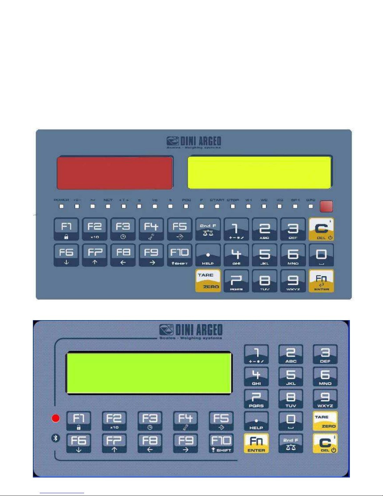
4. FRONT PANEL KEYS
3590E:
CPWE:
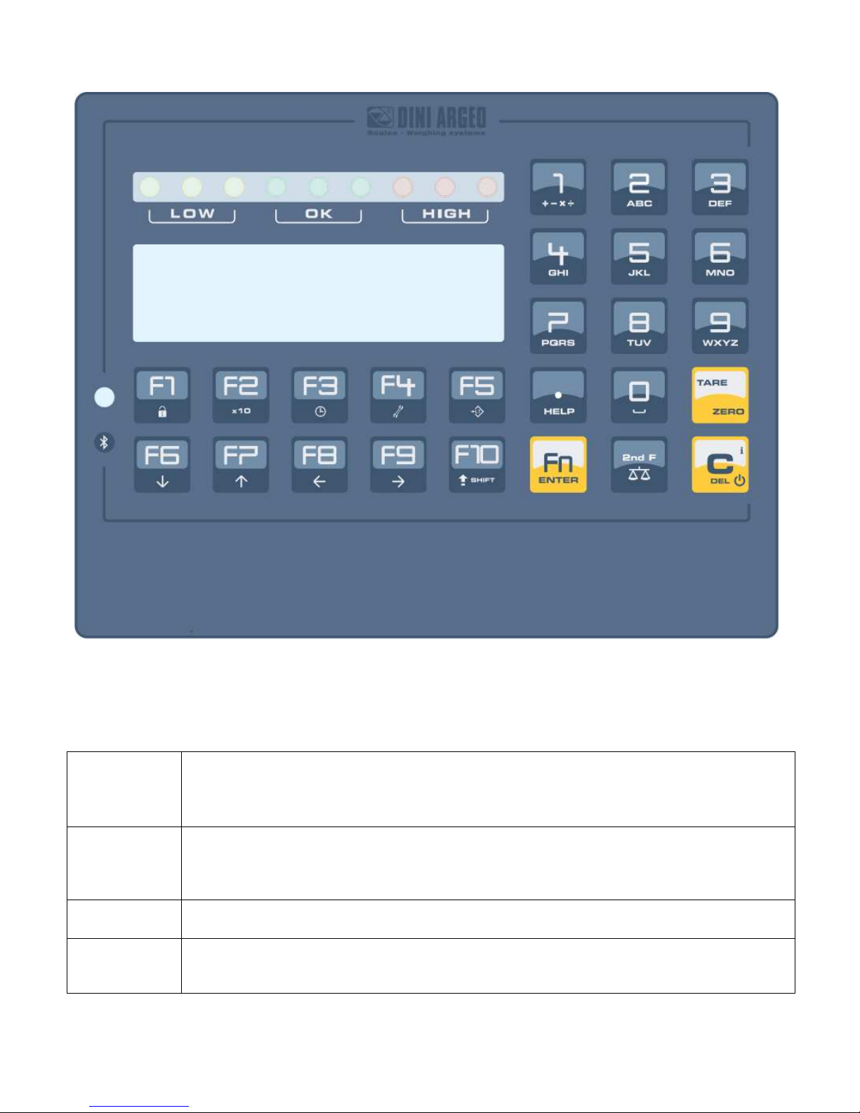
3590EKR, 3590EXP, 3590EXT, CPWE, CPWET series indicator E-AF09_02_13.01_EN_U
13
CPWET
4.1 FUNCTION OF THE KEYS
In the following section, and later on in the manual, the keys’s functioning is described in accordance to how these are
configured by factory.
It is possible to customise the functionality of the keys through the << F.KEYS >> step.
C/DEL
- Turns the instrument on/off
- If pressed for an instant, it clears the tare value.
- Exits the parameter without confirming and saving the modifications.
- In the numeric input phase, it quickly clears the present value
TARE/ ZERO
- If pressed for an instant it carries out the semiautomatic tare, or cancels the value of tare if the gross
weight is 0.
- If pressed at length, it clears the displayed gross weight, if it’s within the percentage configured in the
<< 0.PErC >> step.
Fn/ENTER
- In the alphanumeric input phase, it confirms the entry made.
- In the menu it allows to enter a step or to confirm a parameter inside a step.
2nd F
- In the
<< F.Keys >>
step, if pressed for an instant, the list of the available
functions appear
and it is possible to choose one of them.
- If pressed together with the other keys, it allows carrying out a specific function. (see section 4.1.1)

3590EKR, 3590EXP, 3590EXT, CPWE, CPWET series indicator E-AF09_02_13.01_EN_U
14
./HELP
In the calculator mode or when edits printer format, if pressed, the display
shows some help
descriptions.
In the numeric or alphanumeric input phase, it enters, in this order, the following characters: . , ; : # < > \
| ” % & / ( ) = ? ^ ’ [ ] { };
F1
In the
<< F.Keys >>
step, if pressed for an instant, it is possible to set
the default key functions.
- In the numeric or alphanumeric input phase, it allows to copy entered characters.
- If pressed for an instant, it enters into the CUSTOMER DATABASE.
- If pressed at length, it locks and unlocks the instrument’s keyboard (except the C key).
F2
- In the numeric or
alphanumeric
input phase
, it allows to stick with copied characters.
- If pressed for an instant, it enters into the MATERIAL DATABASE.
- If pressed at length, the weight visualisation function with sensitivity x 10 is enabled
F3
- If pressed for an instant, it enters into the
VEHICLE DATABASE
.
- If pressed at length, one can adjust the date and time of the instrument.
F4
- If pressed for an
instant
, it allows to fill in the free texts
,
(only
if configured
).
- If pressed at length, it enters the instrument’s diagnostics menu.
F5
- If pressed at length, it locks/unlocks the tare.
- Commands the data transmission to the printer serial port.
F6
- If pressed for an instant, it
starts
the simple axle totalisation or the
i
nput
axle totalisation (with
Input/Output function enabled).
- In the numeric or alphanumeric phase, it decreases the blinking digit.
- It allows scrolling ahead inside the menu steps or in the parameters within a step.
F7
- If pressed for an instant, it
starts output axle totalisation (with Input/Output function enabled).
- In the numeric or alphanumeric input phase, it increments the blinking digit.
- It allows scrolling backwards in the menu steps or in the parameters within a step.
F8
- If pressed for an instant, it executes the printing and the zeroing of the partial total.
- In the numeric or alphanumeric input phase, it selects the digit to be modified from right to left.
F9
- If pressed for an instant, it allows to manually close the
automatic
axl
e totalisation cycle with
consequent determination of the total weight. See section 13.2.2, 13.2.3, 13.3.2 and 13.3.3.
- In the numeric or alphanumeric input phase, it selects the digit to be modified from left to right.
F10
- If pressed for an instant, i
t allows to reset the
automatic
axle totalisation cycle, cancelling all the
totalized axles. See section 13.4.1
- In the numeric or alphanumeric input phase, introduces a space between two characters.
NUMERIC
KEYBOARD
Entry of digits or characters.
- During weighing, these enter a numeric value with which it’s possible to:
1) Set the tare value, by pressing subsequently the TARE key (see section 7.2).
2) Sum, subtract, or multiply the value entered from the keyboard to the current tare (see the 15.3
CALCULATOR section).
3590EKR, 3590EXP, 3590EXT, CPWE, CPWET series indicator E-AF09_02_13.01_EN_U
15
4.2 "2ndF" KEY: SECOND FUNCTION OF THE KEYS
In the weighing phase, by pressing the 2ndF key together with another key, it’s possible to execute various functions
(continue reading the manual for the details of the functions):
2ndF
F1
Pri
nt/
Clearing
of Customer Total.
2ndF
F2
Print/
Clearing
of Material Total.
2ndF
F3
Print/
Clearing
of Vehicle Total.
2ndF
F4 Deselecting
all the elements selected from the database
s.
2ndF
F5
Repetition of the last printout made.
2ndF
F8
Net/Gro
ss Conversion
2ndF
F9
Change LCD visualization
2ndF
C
Causes the display of the present metric scale information
(see section 9).
4.3 ENTERING ALPHANUMERIC TEXT
It might be necessary, while the weighing system is working, to enter some alphanumerical texts such as descriptions,
alphanumerical messages (operator, lot number, customer, etc.).
To enter the characters one uses the 0 to 9 keys.
By pressing one of these keys a few times, the characters shown on the key will be shown on the display: initially the first
letter in the bottom left will appear, and then the other characters towards the right.
After digiting a character, the blinking cursor, after a few instants, advances automatically of a position.
When the maximum number of characters has been reached, the indicator emits an acoustic signal and the cursor remains
in that positions.
TAKE NOTE:
In the updating of a text, if the cursor is at the beginning of the text and the first key pressed is C or a character/number key,
all the entered characters will be deleted.
Function of the keys
F5 S
witches the writing mode from “numeric”
(nuM)
to “characters”
(ChAr)
.
In the nuM mode one enters just the numbers, while in the ChAr mode one can enter all the characters of
a key. The last writing mode selected is stored by the instrument.
C If p
ressed for an instant, it
cancels the written characters: first the characters that follow the cursor are
cancelled; than those that precede it, one at a time.
If pressed at length, it deletes all entered characters.
With empty text, it exits the entry phase without confirming.
SHIFT
It enters a space in the middle of a text.
./HELP
If pressed a few times it allows entering the following characters:
. , ; : # < >
\ | ” % & / ( ) = ? ^ ’ [ ] { }.
0 In “characte
rs” mode
(ChAr),
by pressing once
, a space is entered;
by pressing twice it enters the “0”
character.
1 In “characters”
mode (ChAr),
when
pressed repeatedly, it
allows to enter the following symbols:
? ! 1 @ ’ + – * / = ~ € „ … † ‡ ˆ ‰ š < OE ž ı ’ “ ” • – – ˜ ™ Š > oe ž ¢ £ ¤ ¥ ¦ § ¨ © ª « ¬ - ® ‾ ° ± ² ³ ´ µ ¶ · ¸
¹ º » ¼ ½ ¾ ¿ ã.
Moves the blinking cursor to the left or to the right.
Scrolls in one sense or the other the list of all the enterable characters (0,
1…9, A, B…Y, Z)
Examples:
- To enter the letter “B” one should press the “2” key twice in the ChAr mode.
- To enter the number “3” one should press the “3” key four times (in the ChAr mode) or press the F5 key (one passes to
the nuM mode) and press the “3” key once.
3590EKR, 3590EXP, 3590EXT, CPWE, CPWET series indicator E-AF09_02_13.01_EN_U
16
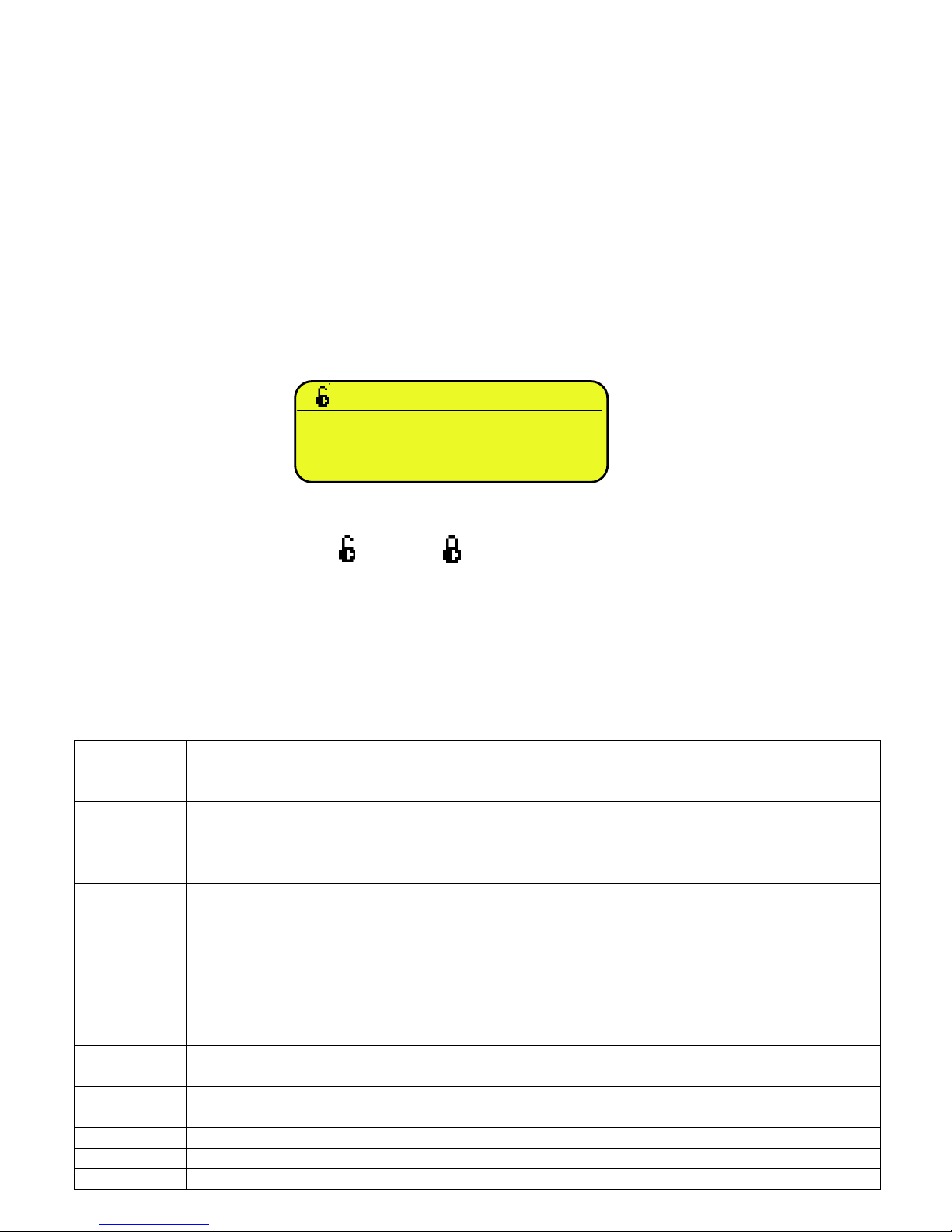
4.4 DISABLING THE KEYBOARD
It is possible to disable all the keyboard functions (except the C key for turning on and off), in order to avoid undesired
pressings of the scale keys:
- To lock the keyboard, press at length the F1 key: the display shows the “LoCK” message for a few instants. Now the
keyboard is LOCKED: if one presses a key, the display shows for a few instants the “PRESS AT LENGTH F1 FOR
UNLOCKING” message.
- To unlock the keyboard, press again at length, the F1 key: the display shows the “unLoCk” message for a few instants.
NOTE: It’s possible to lock all keys individually in a permanent way through the TECHNICAL SET-UP, TECH.MAN.REF.
4.5 HELP MENU
By pressing at length the HELP key it is possible to access a menu containing the list of keys with the relative function, and
status (locked or unlocked) indication.
The display shows:
- in the upper part: the key, followed by the code of the linked function in the << F.Keys >> step, and a symbol
indicating whether the key is unlocked ( ) or locked ( ) in the << EN.KEYS >> step.
- in the lower part: the description of the linked function.
Scroll the list with the arrow keys , press the C key to exit.
4.6 INDICATOR CONNECTED TO REMOTE KEYBOARD
It’s possible to connect a PC keyboard (optional), used to emulate the functions of the keys of the indicator.
The keys are managed in the following way:
Esc
-C key.
- If pressed at start-up, it allows entering in the technical set-up.
In the alphanumeric input, it deletes all entered characters.
and Canc
-C key.
- If pressed at start-up, it allows entering in the technical set-up.
In the alphanumeric input, it cancels first the characters which follow the cursor, then the ones which
precede it, one at a time.
Enter
- Fn
key.
- Confirms the entered value.
- Enters the displayed step
Numeric and
alphanumeric
keys, SHIFT
and CAPS
LOCK
- Quick entry of a numeric and alphanumeric string: through the CAPS/LOCK or SHIFT key it is possible to
switch from the capital letters to the lower case letters, and vice versa, or enter the second character
corresponding to the key (for example ", %, &, /, ? ). The entered string is shown on the LCD display.
Cursor keys
- Scroll the parameters
- Increase or decrease the blinking digit while entering a value.
Cursor keys
- When entering a value or an alphanumeric string, it scrolls the digits to the right or to the left.
F1, F2….F10
F1,F2….F10 keys.
F11 2ndF
key
F12 TARE
key.
F1:302
C
CUSTOMER
DATABASES
3590EKR, 3590EXP, 3590EXT, CPWE, CPWET series indicator E-AF09_02_13.01_EN_U
17
The PC keyboard also allows to enter a numeric or alphanumeric string (max.32 characters) and then press a key to execute
the corresponding quick function.
For example, if the function 122 (Input text 1 configuration) is combined to the F4 key (see << F.KEYS >> step,
TECH.MAN.REF.), through PC keyboard it’s possible to enter a text and the press F4 to quickly modify the input text 1.
NOTE: through the remote keyboard, it’s not possible to carry out the functions made by pressing the keys at length.
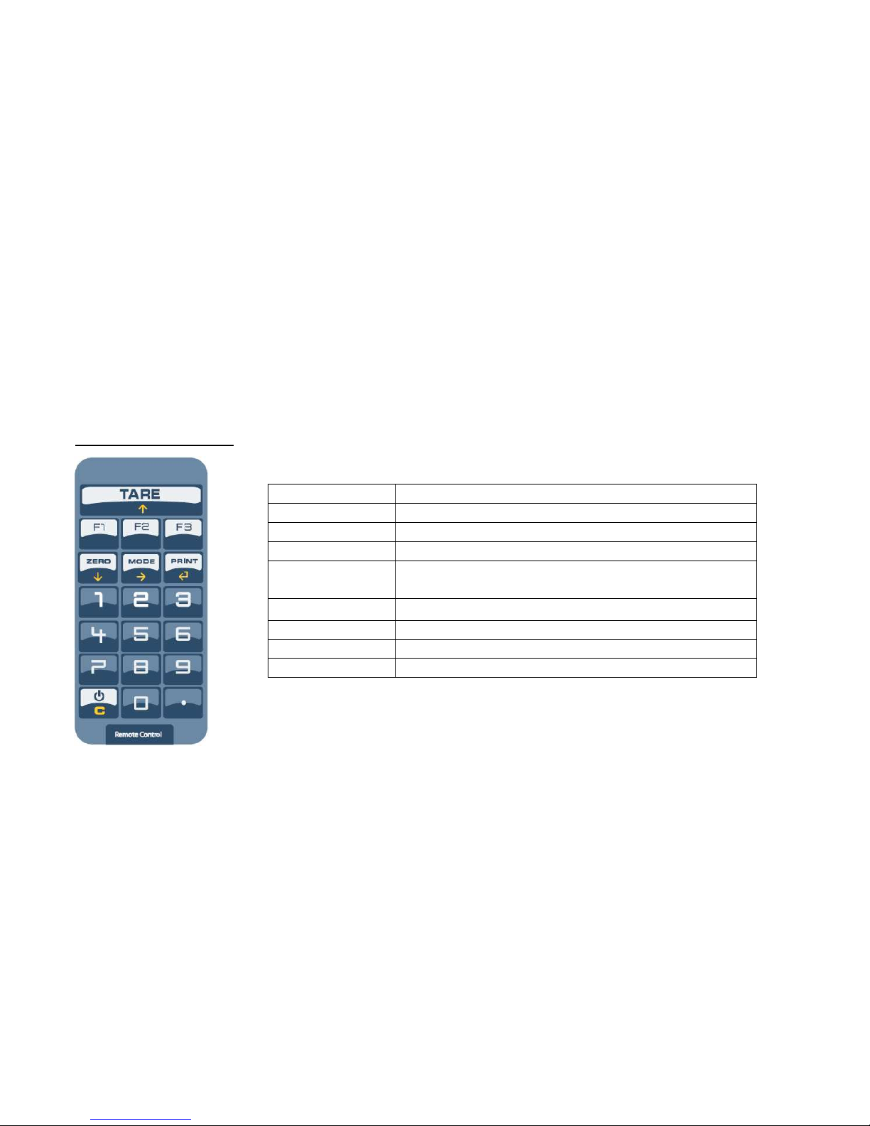
4.7 REMOTE CONTROL
Depending on the model of indicator, it is possible to remotely control the instrument through one of the following types of
remote controls: 19-key infrared (ir),18-key infrared (ir) or 6-key radio (rd).
The type of remote control to be used must be selected in the Setup environment, in the << inF.rEd >> step
(TECH.MAN.REF.).
NOTE: The infrared remote controls are for indoor use only.
4.7.1 “19-KEY” INFRARED REMOTE CONTROL
With this type of remote control, the functioning of the keys will be as described in the following table.
FUNCTION OF THE KEYS
KEYBOARD
KEY OR FUNCTION EMULATED
F1…F3
F1…F3 keys
C C key
NUMERIC KEYS
Entry of digits or characters
TARE /
Tare/zero function
or increase of a digit while entering a
value
.
.
/HELP key
ZERO /
Decrease of a digit while entering a value
MODE /
Scrolls the digits to the right while entering a value
PRINT /
Confirms the entered value or enters the displ
ayed step
3590EKR, 3590EXP, 3590EXT, CPWE, CPWET series indicator E-AF09_02_13.01_EN_U
18
4.7.2 “6-KEY” RADIO REMOTE CONTROL
With this type of remote control, the functioning of each key can be programmed so that it is matched to one of the available
keys of the indicator.
This configuration must be carried out in the Setup environment, in the << inF.rEd >> step (TECH.MAN.REF.), after the
selection of this type of remote control.
By pressing the ./HELP key of the indicator, it’s possible to see, while weighing, the list of the functions matched to the keys
of the indicator and also to the keys of the remote control (see section 4.1.4 “HELP MENU”).
EXAMPLE OF CONFIGURATION
USE OF MORE REMOTE CONTROLS WITH ONLY ONE INDICATOR
If one works with only an indicator, it is possible to use any 6-key remote control, without combining it to the indicator,
therefore without limiting the number of usable remote controls.
To enable this mode one has to first select “RD 6 BR” in the << inF.rEd >> (TECH.MAN.REF.).
USE OF MORE REMOTE CONTROLS WITH SEVERAL INDICATORS IN THE SAME AREA
If one needs to use several indicators in the same area, it is possible to combine each remote control to the desired indicator,
in order to execute the function only on it and therefore avoid emulating the function on all indicators in use.
By enabling this mode it will be possible to combine up to 3 different remote controls (e.i. for 3 different operators) for each
indicator.
To enable this mode one has to first select “RD 6” in the << inF.rEd >> (TECH.MAN.REF.).
To link a new remote control to the indicator one has to:
- press at length 1 and 2 keys together (3 seconds).
- the instrument displays "aut.rd?"
- press the ENTER key of the indicator
- the new remote control is linked
To remove the linking of a remote control one has to:
- press at length 1 and 2 keys together (3 seconds).
- the instrument displays "aut.rd?"
- press the C key of the indicator; if the remote control was previously linked, it will be removed.
3590EKR, 3590EXP, 3590EXT, CPWE, CPWET series indicator E-AF09_02_13.01_EN_U
19
5. DISPLAY FUNCTIONS
During the weighing the displays are subdivided mainly in 3 sections, shown in the figure below:
- WEIGHT
- STATUS INDICATORS (led pilot lights and / or graphic symbols)
- DATA (two lines in the 3590E; one or two lines in the CPWE, depending on the weight zoom function described in the
following section). See section 5.4.
Figure 1: 3590E displays
Figure 2: CPWE/CPWET display
CUS MAT VEH
PT: 1.000kg
1 CUS MAT VEH
PT: 1.000kg
WEIGHT
STATUS
INDICATORS
STATUS
INDICATORS
DATAS
WEIGHT
STATUS
INDICATORS
STATUS
INDICATORS
DATAS
3590EKR, 3590EXP, 3590EXT, CPWE, CPWET series indicator E-AF09_02_13.01_EN_U
20
5.1 WEIGHT ZOOM (available only on CPWE and CPWET models)
The zoom function allows to increase the size of the weight digits, in order to ease the reading from a distance; with the
active zoom, the data is shown on a single line.
Through the << ZOOM.W >> step, one can disable/enable the function and set a delay which determines the activation
mode:
- Always active function (with delay equal to 0), or
- Disabled function at the pressing of a key and re-enabled automatically when the keyboard inactivity time reaches the
configured delay period (with delay greater than 0).
5.2 STATUS INDICATORS
LED FUNCTION
POWER
Indicates the type of indicator power supply:
- red pilot light: through built-in power adapter;
- green pilot light: through battery (charged battery);
- pilot light off: through battery (discharged battery).
0
Indicates that the weight detected by
the weighing system is near zero, including the interval of 1/4 +1/4
of the scale’s division.
~
Indicates that the weight is unstable.
NET
Indicates that the weight shown by the LED display is a NET WEIGHT.
T
Indicates that a tare value has been acquired or entered.
g
Indicates that the unit of measure in use is the gram.
kg
Indicates that the unit of measure in use is the kilogram.
t
Indicates that the unit of measure in use is the ton.
PCS
Not used in this application
F
Indicates that an axle totalization cycle is in execution.
START
Not used in this application
STOP
Not used in this application.
W1 W2 W3
See section 8.
SP1
Not used in this application
SP2
Not used in this application
CUS MAT VEH
3590EKR, 3590EXP, 3590EXT, CPWE, CPWET series indicator E-AF09_02_13.01_EN_U
21
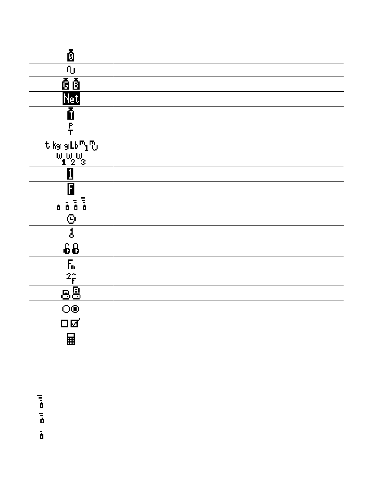
SYMBOLS FUNCTIONS ON THE LCD DISPLAY
5.3 BATTERY LEVEL INDICATION
The indicator is able to recognise whether it is powered by mains or by battery, and to indicate its charge level; to enable the
battery level indication, one should configure the << bt.LEVEL >> step.
The charge level is shown during weighing by the battery symbol.
- : charged battery.
-
: partially charged battery.
- : discharged battery: connect the indicator to the mains for recharging the battery (if provided by that model) or replacing
the battery.
SYMBOL ON LCD DISPLAY
FUNCTION
The weight detected by the weighing system is near the zero, included within the interval
of –1/4 and +1/4 of the scale division.
The weight is unstable.
The displayed weight is a GROSS WEIGHT (depending on the software language).
The displayed weight is a NET WEIGHT.
A tare value has been acquired.
A manual tare value has been entered.
Unit of measure in use: ton, kilogram, gram, pounds, millilitres, or millivolts.
Active weighing range, see section 8.
Active scale (always 1).
Indicates that an axle totalization cycle is in execution.
Battery charge level: see section 5.3.
Active during the configuration of the date and time.
Locked keyboard, see section 4.4
In the HELP menu these respectively indicate whether a key is unlocked or locked in the
SETUP level (<< En.KEYS >> step, see section 4.5)
The Fn key has been pressed.
The 2nd F key has been pressed.
Transmission of the data to the printer serial port under way.
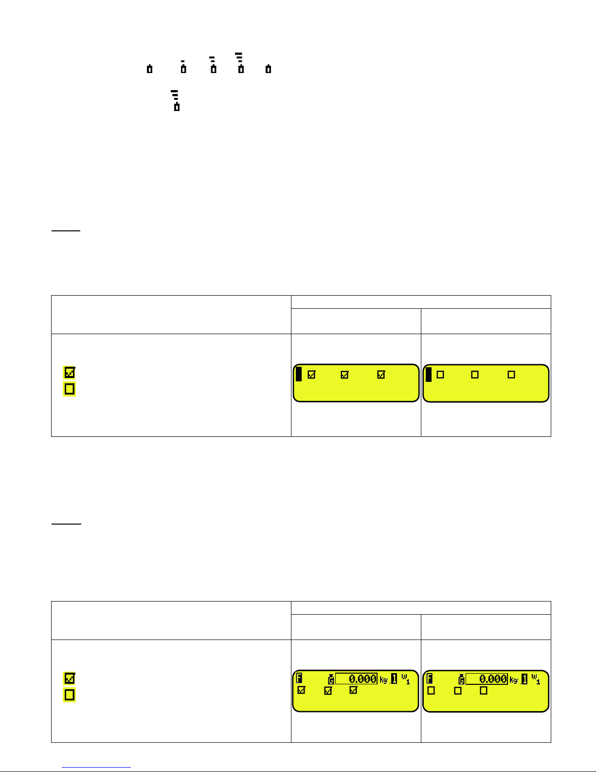
Inside the step, these respectively indicate an unselected or selected parameter.
These indicate
respectively
if an element of the database is
unselected or
selected (see
section 5.4).
Active calculator function, see section 15.3 CALCULATOR.
3590EKR, 3590EXP, 3590EXT, CPWE, CPWET series indicator E-AF09_02_13.01_EN_U
22
The indicator shows also when the battery is being recharged (if provided for the model):
RECHARGE PHASE: …
COMPLETED RECHARGE:
NOTES:
- During the recharge the instrument can be normally used.
- The instrument automatically turns off when the voltage goes below the minimum level.
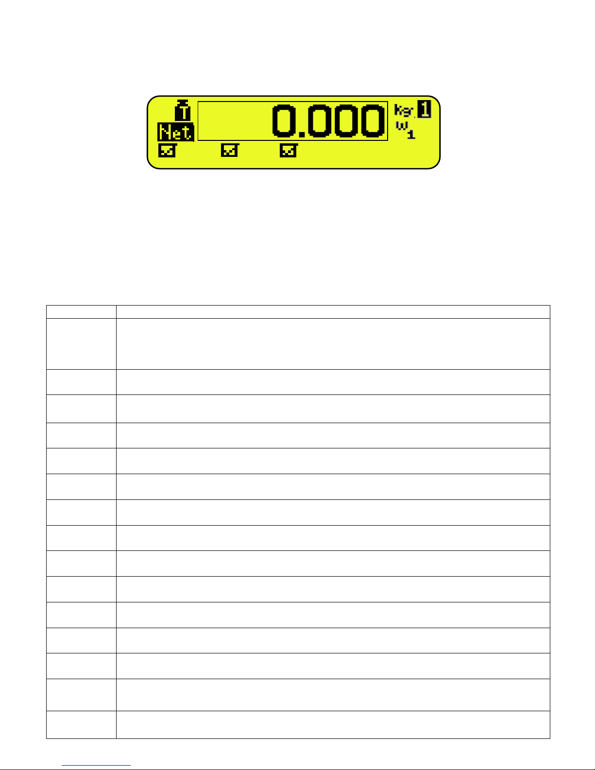
5.4 DISPLAYED DATA
3590E:
The data is displayed on two lines and depends on the status of the instrument:
- When not in the axle totalization cycle, the visualization will be as follow:
VISUALISATION
EXAMPLE
S
WITH ELEMENT
SELECTED
WITH ELEMENT
NOT SELECTED
- Indication of the selected elements (CUS:customer /
MAT:material / VEH:vehicle):
Element selected
Element not selected
- PT is Preset tare (if set) to be subtracted from the total
accumulated weight (see section 13.3.6).
- During the axle totalization cycle the display will guide the operator to execute the weighing procedure depending on the
selected functioning mode. Refer to section 13 for details.
CPWE:
VISUALISATION WITH NON ACTIVE WEIGHT ZOOM
The data is shown on two lines under the “weight” section depending on the status of the instrument:
- When not in the axle totalization cycle, the visualization will be as follows:
VISUALISATION
EXAMPLE
S
WITH ELEMENT
SELECTED
WITH ELEMENT
NOT SELECTED
- Indication of the selected elements (CUS:customer /
MAT:material / VEH:vehicle):
Element selected
Element not selected
- PT is Preset tare (if set) to be subtracted from the total
accumulated weight (see section 13.3.6).
CUS MAT VEH
1 CUS MAT VEH
PT:
10
00kg
1 CUS MAT VEH
PT:
10
00kg
CUS MAT VEH
PT: 1.000kg
3590EKR, 3590EXP, 3590EXT, CPWE, CPWET series indicator E-AF09_02_13.01_EN_U
23
- During the axle totalization cycle the display will guide the operator to execute the weighing procedure depending on the
selected functioning mode. Refer to section 13 for details.
VISUALISATION WITH ACTIVE WEIGHT ZOOM
The data is shown on one line under the “weight” section depending on the status of the instrument:
- When not in the axle totalization cycle, the visualization will be as follows:
VISUALISATION
EXAMPLE
S
WITH ELEMENT
SELECTED
WITH ELEMENT
NOT SELECTED
- Indication of the se
lected elements (CUS:customer
/
MAT:material / VEH:vehicle):
Element selected
Element not selected
5.4.1 LCD DISPLAY CUSTOMIZATION (ONLY FOR 3590E INDICATORS)
On the 3590E models it is possible to customize the data displayed on the LCD display, through the print format 99 (see the
section “DISPLAY CUSTOMIZATION”, TECH.MAN.REF.), by using the DiniTools™ software.
By pressing in sequence the Fn and F9 keys it’s possible to activate the customized visualization.
The default configuration for this visualization is the following:
If more than 4 lines have been programmed, it’s possible to scroll the visualizations by pressing in sequence the Fn and F9
keys.
Once that this visualization has been activated, press in sequence the 2ndF and F9 keys to display again the standard
visualisations described in the previous sections.
CUS
MAT
VEH T
1.000
CUS
MAT
VEH
first description of the selected material
first description of the selected customer
first description of the selected vehicle
MAT.:
MATERIAL 1
CUS.: CUSTOMER 1
VEH.: TRUCK 1
TARE
0.000
kg
1

3590EKR, 3590EXP, 3590EXT, CPWE, CPWET series indicator E-AF09_02_13.01_EN_U
24
5.5 MESSAGES OF THE INSTRUMENT
While using the indicator, it is possible to incur into the following errors:
5.5.1 INSIDE THE SET-UP OR MENU OR AT START-UP
MESSAGE DESCRIPTION
Error S X Cell Y Communication error on scale X (E.G. Range 1), to Platform number Y
Err. – 98
Connection error between the indicator and the platforms, after have showed this
error, the instrument, show which platform has problems.
C.Er. – 8.03
When carrying out the multirange or multidivisional calibration, the ranges have not
been entered in an increasing manner (RANGE 1 < RANGE 2 < RANGE 3).
C.Er.
– 36
CALIBRATION ERROR
During the calibration some internal negative points have been calculated:
- the calibration point is less than the zero point.
-
the signal is negative (check the connections)
Er – 37 / alternately with No.Cal
CALIBRATION ERROR
During the calibration some internal points less than the minimum value have been
calculated:
- the calibration point is equal to the zero point.
-
A capacity too high in relation to the division has been set.
Err. – 38
NO CALIBRATION
Range not valid: please check that RANGE 1 < RANGE 2 < RANGE 3.
Er – 39
NO CALIBRATION
Invalid calibration range number (there is the value 0 or values greater than 3); one
must execute a TECHNICAL DEFAULT (dFLt.t parameter of the SET-UP
environment), if not already executed previously, and carefully carry out the
calibration.
Er – 40
The value 0 is in the “range 1” parameter of the calibration; one must execute a
TECHNICAL DEFAULT (dFLt.t parameter of the SET-UP environment) and carefully
carry out the calibration.
Er – 41
The value 0 is in the “diV 1” parameter of the calibration; one must execute a
TECHNICAL DEFAULT (dFLt.t parameter of the SET-UP environment) and carefully
carry out the calibration.
Err. – 72
Equalizati
on coefficient adjustment not allowed because a too low sample weight has
been used.
Err. – 85
Equalization coefficient adjustment not allowed because the instrument has not been
calibrated.
ErPnt
During the acquisition of a calibration point, a null val
ue from the converter has been
read.
hW-Err
HARDWARE ERROR: software not compatible with the installed hardware; t
he
hardware expansion component, which allows the software to function, is missing.
EXITING SETUP:
SAVE ?
The instrument requests the saving
when exiting the set
-
up; press
ENTER
to confirm
or C to not continue..
SURE?
The instrument requests a confirmation before proceeding: press
ENTER
to confirm
or C to not continue.
Error
Generic error. Possible motives can be:
- Division not valid: please check that DIVISION 1 < DIVISION 2 < DIVISION 3;
- An error has taken place in the connection, configuration, equalisation,
calibration of the cells, etc.
EXECUTION
AUTOZERO
“autozero at start-up” function is active (see section 3.4)
 Loading...