

Dini Argeo 3590EGT Series User Manual
Indicators series 3590EGT EGTCHECK_05_15.08_IT_U
USER MANUAL
WEIGHT INDICATOR
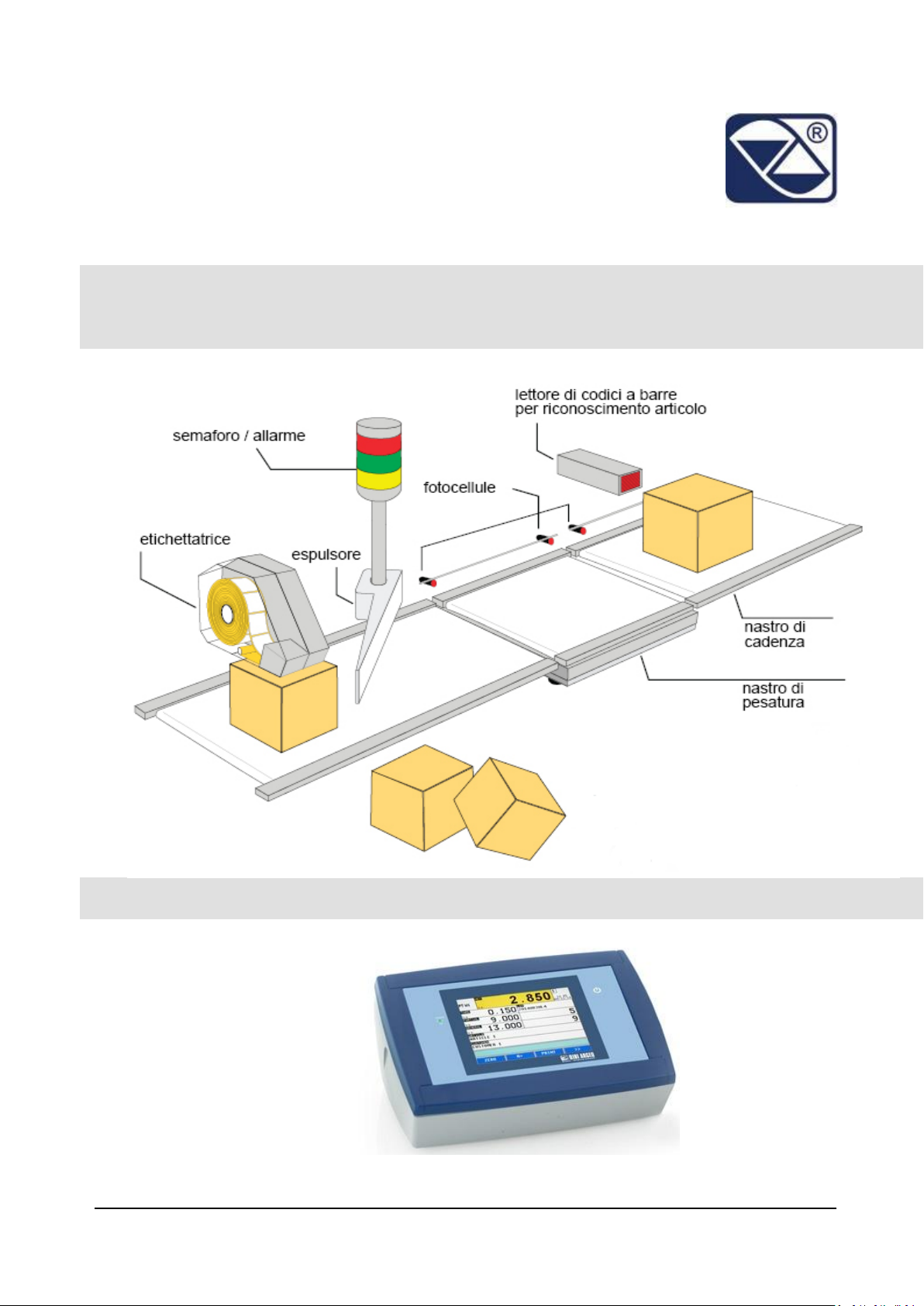
EGTCHECK: DINAMIC OR STATIC WEIGHT CONTROL ON
TAPE
Indicators series 3590EGT
1

3590EGTCHECK_05_15.08_IT_U
INDEX
1 INTRODUCTION .......................................................................................................................................... 5
2 TECHNICAL SPECIFICATIONS ...................................................................................................................... 7
3 INSTALLATION ............................................................................................................................................ 8
3.1 Case and dimensions ....................................................................................................................... 8
3.2 Connectors....................................................................................................................................... 9
3.3 Power supply ................................................................................................................................... 9
3.4 Start up .......................................................................................................................................... 10
3.5 Turning off the instrument ............................................................................................................ 10
4 INDICATOR PARTS .................................................................................................................................... 11
4.1 display ............................................................................................................................................ 12
4.1.1 Display indicators .............................................................................................................. 14
4.1.2 Numeric input ................................................................................................................... 14
4.1.3 Alphanumeric input .......................................................................................................... 14
5 MAIN FUNCTIONING DESCRIPTION ......................................................................................................... 15
5.1 Zeroing ........................................................................................................................................... 15
5.2 Tare ................................................................................................................................................ 16
5.2.1 Semiautomatic tare .......................................................................................................... 16
5.2.2 Preset tare ........................................................................................................................ 17
5.2.3 Link a preset tare to an article .......................................................................................... 17
5.2.4 Tare cancellation............................................................................................................... 17
5.2.5 Locked/unlocked tare ....................................................................................................... 17
5.3 Input texts...................................................................................................................................... 18
5.4 Databases ...................................................................................................................................... 19
5.4.1 Insertion ............................................................................................................................ 19
5.4.2 Modification ..................................................................................................................... 20
5.4.3 Cancellation ...................................................................................................................... 21
5.4.4 Alphanumeric search ........................................................................................................ 22
5.4.5 Search by element index .................................................................................................. 23
6 SYSTEM STATUS ....................................................................................................................................... 24
7 WEIGHING PROCEDURE ........................................................................................................................... 25
2

7.1 SYSTEM STATUS CONTROL ............................................................................................................ 25
7.2 ENABLING/DISABLING THE WEIGHIG CYCLE ................................................................................. 25
7.3 DESCRIPTION OF THE CYCLE PHASES............................................................................................. 26
7.4 WEIGHT ACQUISITION ................................................................................................................... 26
7.4.1 AT HALF WITH A SENSOR .................................................................................................. 26
7.5 DESCRIPTION OF THE SYSTEM ....................................................................................................... 26
7.5.1 IN MOTION WITH 1 PHOTO CELL ...................................................................................... 28
7.5.2 IN MOTION WITH 2 PHOTO CELLS .................................................................................... 29
7.5.3 IN MOTION WITHOT PHOTO CELLS .................................................................................. 30
7.6 TOLERANCE CHECK ........................................................................................................................ 31
7.6.1 CHECKING WITH ARTICLE AND T1, T2, T3 TOLERANCE SETTING ...................................... 32
7.6.2 CHECKING WITH ARTICLE AND MINIMUM AND MAXIMUM THRESHOLD SETTING ........ 33
7.6.3 CHECKING WITHOUT ARTICLE AND FAST MINIMUM AND MAXIMUM THRESHOLDS
SETTING ......................................................................................................................................... 33
7.6.4 DETERMINATION OF THE TOLERANCE RANGE ................................................................. 33
7.6.5 CHECKING QUANTITIES IN ml ........................................................................................... 34
7.6.6 AUTOMATIC TARGET RECALCULATION AFTER N WEIGHTS WITHIN TOLERANCE ............ 35
7.7 CORRECTION OF THE OUT OF TOLERANCE WEIGHT ..................................................................... 35
7.8 NOT MANDATORY CORRECTION OF THE WEIGHT ........................................................................ 35
7.9 MANDATORY CORRECTION OF THE WEIGHT ................................................................................ 36
7.10 WEIGHT RESULT INDICATION AND ENABLING OF THE LINKED OUTPUTS .................................... 37
7.11 OUTPUTS MANAGED IN THE FUNCTIONING WITH ARTICLE AND TOLERANCE ............................. 38
7.12 STOP AND RESTART OF THE BELTS ................................................................................................ 39
7.12.1 STOP OF BELTS FOR WEIGH OUT OF TOLERANCE/MANUAL EXPLUSION ......................... 39
7.12.2 STOP OF BELTS AFTER EVERY WEIGH ............................................................................... 39
7.12.3 STOP OF BELTS AFTER A NUMBER OF WEIGHTS OUT OF TOLERANCE ............................. 40
7.13 EVACUATION AND AUTOMATIC EXPULSION ................................................................................. 40
7.14 WEIGHING BELT AUTOZERO .......................................................................................................... 40
7.15 CYCLE AND INTERRUPT OF THE WEIGH (NOT WEIGHED PACK) .................................................... 42
7.16 DOWNSTREAM BLOCK ................................................................................................................... 43
7.17 EMERGENCY/MOTOR LOCK ........................................................................................................... 43
7.18 UNDERLOAD/OVERLOAD WEIGHT LOCK ....................................................................................... 43
7.19 CYCLE RESTORAL AFTER POWER OUTAGE .................................................................................... 43
7.20 MANAGEMENT OF CADENCE PHOTOCELL AND BELT ................................................................... 44
3

7.21 ALARM OUTPUT MANAGEMENT ................................................................................................... 45
8 Printouts .................................................................................................................................................. 46
9 Error Messages ........................................................................................................................................ 47
10 Progressives ............................................................................................................................................. 48
10.1 Additional value ............................................................................................................................. 48
10.2 Progressive digits ........................................................................................................................... 48
10.3 Ticket Progressive .......................................................................................................................... 48
10.4 Lot Progressive .............................................................................................................................. 48
4
INTRODUCTION
AVERTENZE
1 INTRODUCTION
This manual was created to help you install and learn all about the functional possibilities of the
purchased indicator.
The instrument is suitable for use in various weighing environments.
Not only does it have all the normal features of high-precision scales, but it also gives you the
possibility to work in specific environments due to the functioning modes contained in the
software implemented in the FLASH MEMORY on the internal board. This makes the instrument
extremely flexible and it can be used in many different industrial applications linked to weighing.
The touch screen, the numerical and function keyboard, allow the operator an easy and
immediate use and provide the microcontroller with DATA ENTRY functions in addition to the
normal weighing functions. The input/output allows the instrument to control various external
devices, to receive external commands, control a printer and communicate with a personal
computer or to be inserted in a network of weight indicators controlled by a PC.
Please note that this instrument is covered by a warranty and MUST NOT BE OPENED BY THE
USER for any reason whatsoever. Any attempt to repair or modify the unit exposes the user to the
risk of electric shock and will invalidate the entire warranty.
If any problems are found in the unit or with the system in which it is used, the fact must be
communicated to the manufacturer or the dealer from whom it was purchased.
In any case, DISCONNECT THE POWER SUPPLY before taking any action.
Do not pour liquids on the weight indicator.
Do not use solvents to clean the weight indicator.
Do not expose the instrument to direct sunlight nor place it near heat sources.
Place or anchor the weight indicator and platform on a non-vibrating base.
All the connections of the indicator have to be made respecting the rules applicable in the
zone and in the installing environment.
Everything not expressly described in this manual has to be considered as improper use of the
equipment.
5
INTRODUCTION
ATTENTION!
Only qualified personnel must perform this operation
ATTENTION!
This is referred to working with live wires: only qualified personnel must
perform this operation.
CE CONFORMITY
IDENTIFIES THE CLASS OF PRECISION.
It identifies an advanced function explained in the technical manual (for
technical personnel).
Do not install in any area where there is a risk of explosion.
The crossed-out wheeled bin on the product means that at the product end of life, it
must be taken to separate collection or to the reseller when a new equivalent type of
equipment is purchased. The adequate differentiated refuse collection in having the
product recycled, helps to avoid possible negative effects on the environment and
health and supports the recycling of the materials of which the equipment is made. The unlawful
disposal of the product by the user will entail fines foreseen by the current regulations.
Used symbols through the manual
6
TECHNICAL SPECIFICATIONS
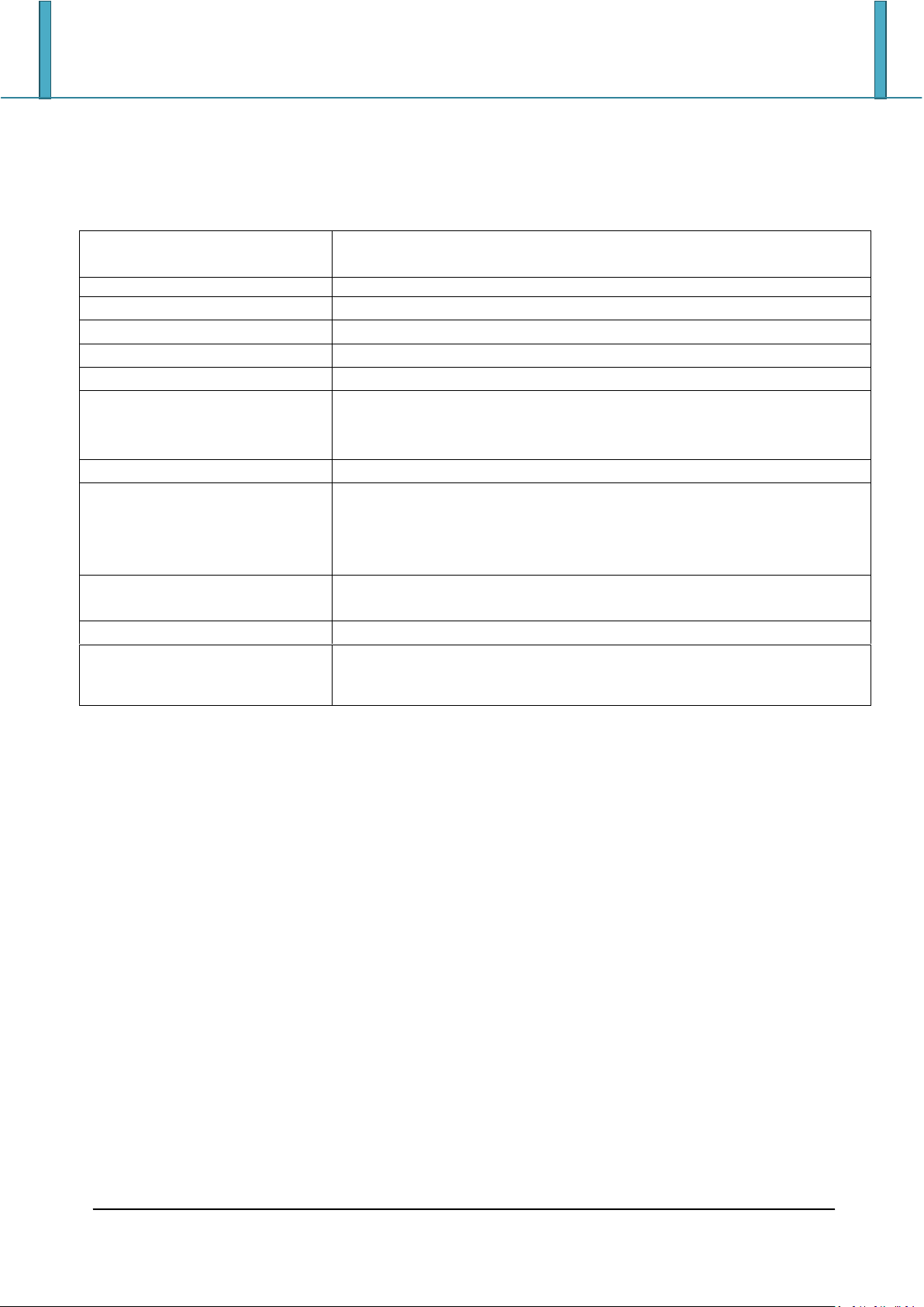
POWER SUPPLY
12 Vdc ( 8 ÷ 24 Vdc in the IO versions), with internal 100 ÷ 240 Vac
(50÷60 Hz) / 12 Vdc adapter.
OPERATING TEMPERATURE
From -10 to +40 °C.
CONVERTER
24 bit Sigma Delta.
AUTOMATIC ZERO DETECTION
Only in gross mode, programmable at +/- ¼, ½, 1, 2 divisions.
ZERO RANGE
Configurable up to +/- 50% of max load capacity.
AUTO ZERO AT START-UP
Configurable up to +/- 50% of max load capacity.
DISPLAY DIVISIONS
10000e, 3 x 3000e for legal for trade weighing, expandable up to
800.000 for internal use (with minimum signal coming from the 1.6
mV/V cell).
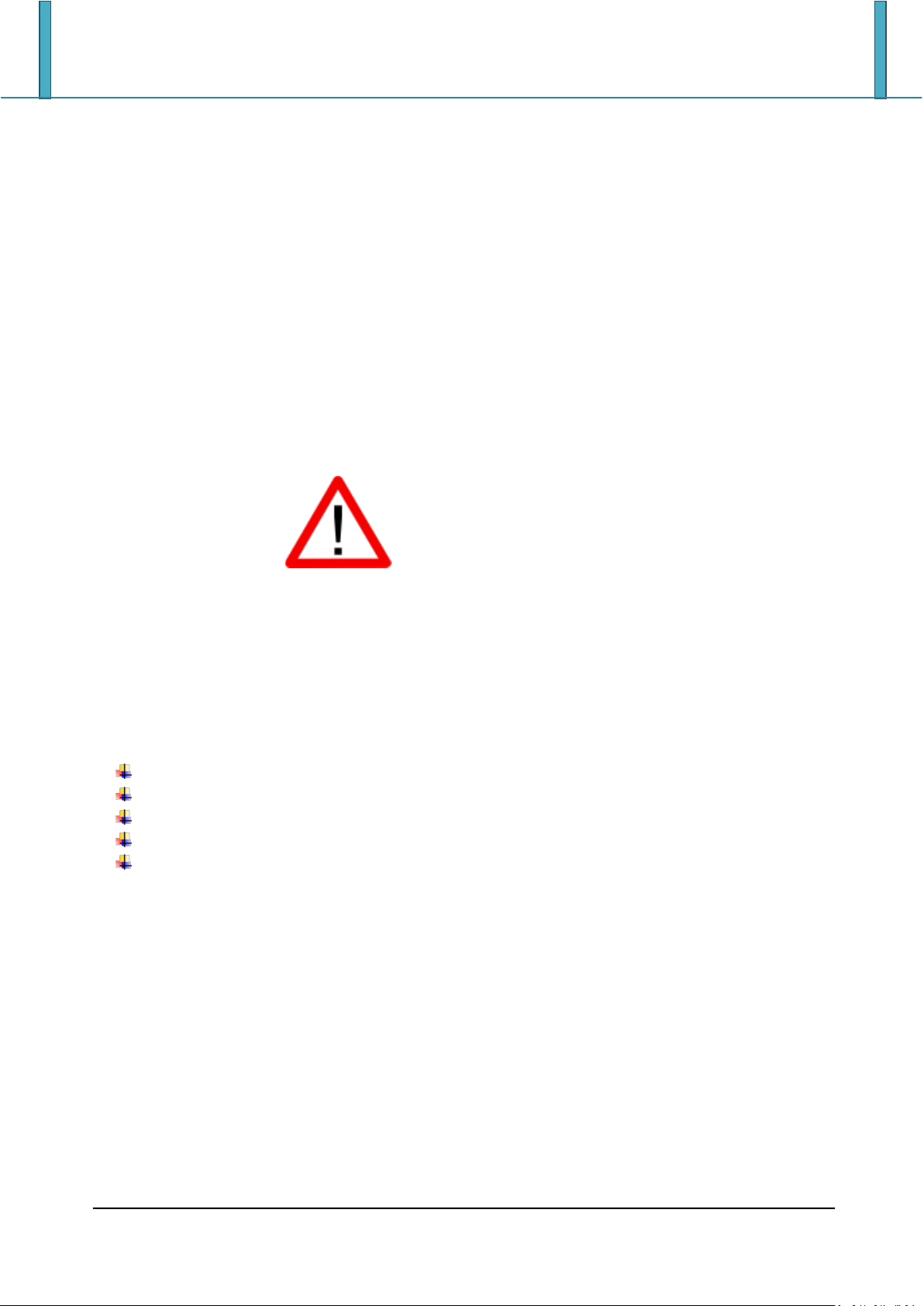
DISPLAY
Graphic touch screen 320x240 dots (black & white)
DATABASE/MEMORY
Articles database of 1000 items (3 descriptions of 20 characters
each, density, target weight, preset tare, tare acquisition before
sampling, and 3 thresholds and number of samples for the
personalized check type)
KEYBORD
Impermeable polycarbonate keyboard (IP65 protection degree), with
membrane keys with audible and tactile feedback.
CLOCK/DATE
Fitted, with buffer RAM.
SERIAL OUTPUTS
- 2 input/output RS232 ports on terminal board/ amp connector.
- 1 input/output RS485 port on terminal board or RS232 on amp
connector.
2 TECHNICAL SPECIFICATIONS
7
INSTALLATION
3 INSTALLATION
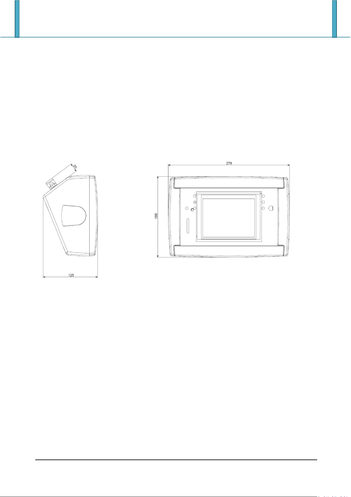
3.1 Case and dimensions
The indicator has a STAINLESS STEEL case, whose external dimensions are shown in the Figure 1. It
can be simply put on a table or fixed to a shelf or column available on request.
NOTE: If the identification plate is supplied separately (therefore not attached to the indicator),
it isadvisable to attach it to the indicator, in order to be able to identify the instrument.
8

3.2 Connectors
Part
Description
1
RJ45 connector
2
Fixing for shelf or column mounting
3
Available for load cells / serial lines / inputs / outputs
4
Power supplì input
1
4 3
2
ET:
INSTALLATION
3.3 Power supply
The indicator is powered with 12Vdc voltage (8 ÷ 36 Vdc in the IO version), through an internal
adapter which converts the 100 ÷ 240Vac, 50÷60Hz mains voltage.
To power the instrument through the 240 Vac mains insert the plug and the adapter to the 240
Vac mains socket.
To connect the indicator to the power mains, the safety regulations must be observed,
including the use of a "clean" line without disturbances or interference caused by other
electronic equipment.
Do not connect other equipment to the same socket as the one that the adapter is in.
Do not step on or crush the power supply cable.
9
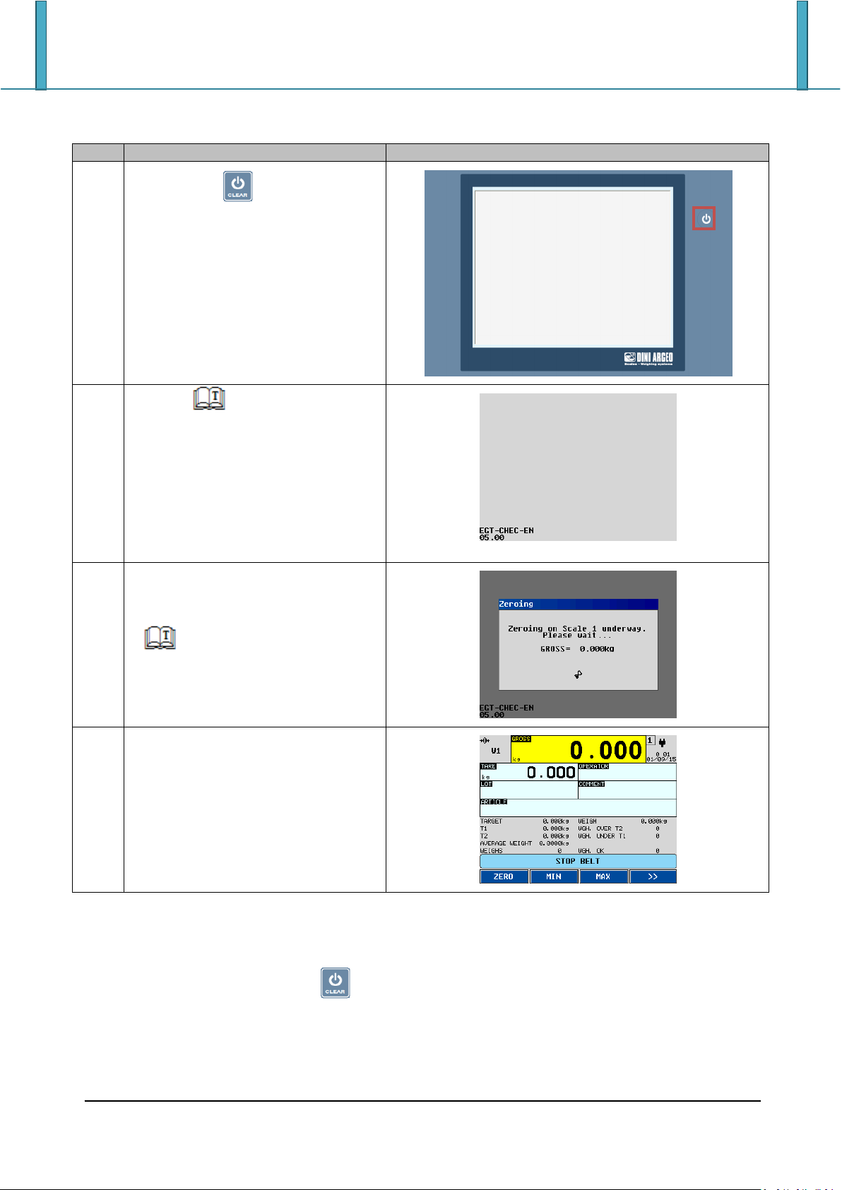
3.4 Start up
Step
Description
Screen
1
Press the key until the
instrument poker on.
2
Il logo ( Logo to show at the
start up) and the software version
appear for some instants.
EGT-CHECK-XX is the name of the
installed software, in which XX
identifies the language.
XX.YY is the installed software
version.
3
The zeroing procedure clears the
weight on the scale within the
tolerance.
( Automatic zeroing at start
up)
4
The main screen appears on the
display.
INSTALLATION
3.5 Turning off the instrument
To turn off the indicator press the key until the logo appears on the display.
10
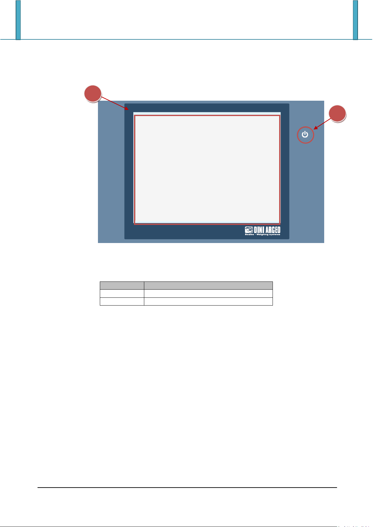
4 INDICATOR PARTS
Part
Description
1
Touch screen
2
Power button
2
1
INDICATOR PARTS
11
INDICATOR PARTS
1 1 2 4 3
6 8
15 14 13
12
11
5 7 9
10 16 18
17
20
19
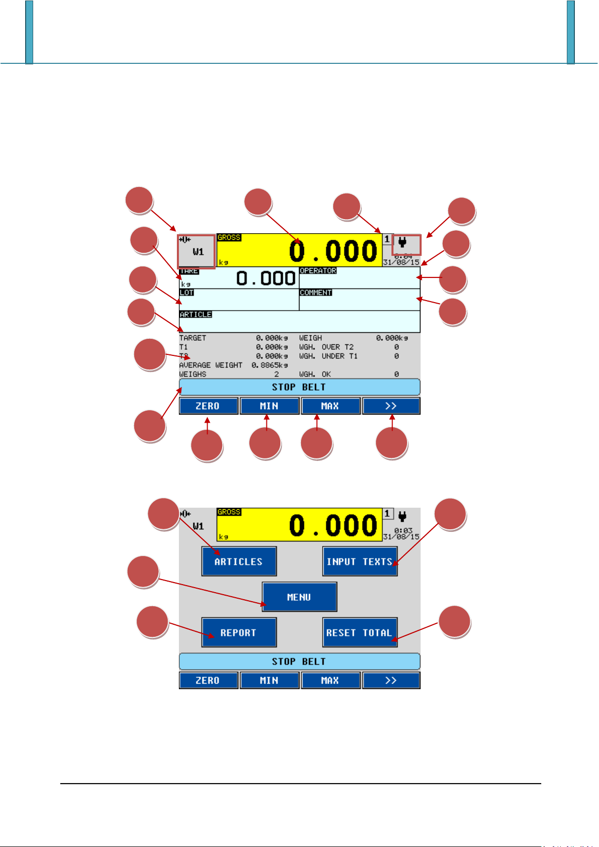
4.1 display
The indicator presents 2 main screens, Figure 1 and
Figure 2:
Figure 1. First main screen
Figure 2. Second main screen
12

INDICATOR PARTS
Element
Description
1
Display indicators
2
Active scale
Touch to switch to the next scale
3
Time and date
Touch to change the date
4
Weight/Volume value on the active scale
Touch to tare the gross weight
5
Tare value
Touch to insert a preset tare
6
Description of the first input text (OPERATOR)
Touch to change the description of the first input text
7
Touch to select the lot
8
Description of the second input text (COMMENT)
Touch to change the description of the second input text and print it
9
Selected article
10
Last weigh
11
System messages area
12
Touch to zeroing the weight
13
Press to set the minimum threshold
14
Press to set the maximum threshold
15
Touch to switch to the next screen
16
Touch to manage the articles database
17
Touch to manage the input texts
18
Touch to access to the indicator functions
19
Touch to print the last sampling report
20
Touch to print the article report
13
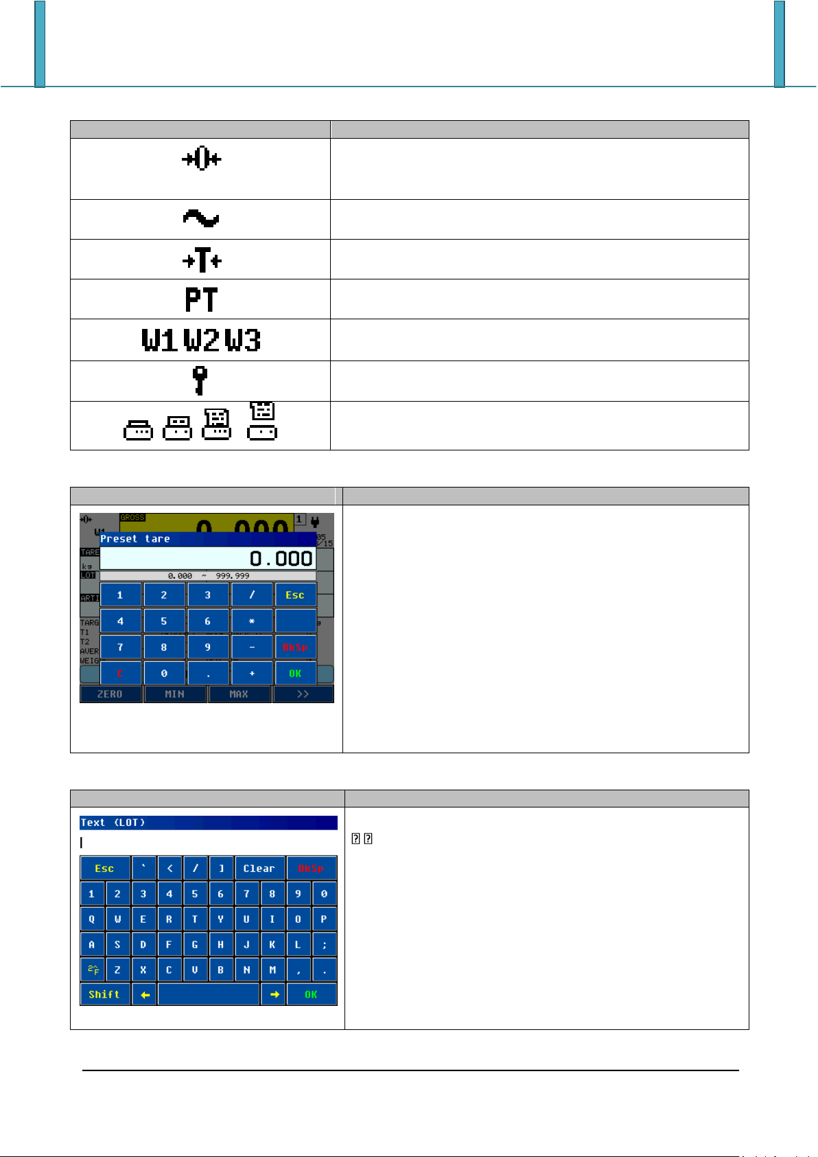
4.1.1 Display indicators
Symbol
Description
Il peso rilevato dal sistema di pesatura si trova in prossimità
dello zero, compreso nell’intervallo –1/4 +1/4 della
divisione della bilancia
The weight in unstable
A tare value has been acquired
A preset tare value has been entered
Active weighing range
Locked keybord
v
Transmission of the data to the printed serial port
underway
Screen
Function
Allows to insert a numeric value within the range.
X ~ Y: valid range for the value to insert
0…9: numbers
.: decimal point
+/-: positive or negative sign
/ * - +: arithmetic operations
C: clears all the value
BkSp: backspace
OK: exit saving the value
Esc: exit without saving the value
Screen
Function
Allows to insert an alphanumeric text.
:scroll left or right
Clear: clears all the text
Bksp: backspace
2^F: switches to special characters
Shift: changes the character case and switches between
letter and number modes
OK: exit saving the text
Esc: exit without saving the text
NOTE: on the first pressed key all the field is replaced
INDICATOR PARTS
4.1.2 Numeric input
4.1.3 Alphanumeric input
14
MAIN FUNCTIONING DESCRIPTION
Group
Description
Scale functions
Operations to the weight (zeroing, tare,…)
Printout
Print functions management
Generic functinos
Generic operations to the indicator (Lock keyboard,
calculator,…)
Diagnostic
Functions to check the peripheral units working state
Input texts
Input texts management
Archivi
Databases management
Check Function
Threshold settings
Totals
Print and reset of the totals
Progressives
Weigh progressives management
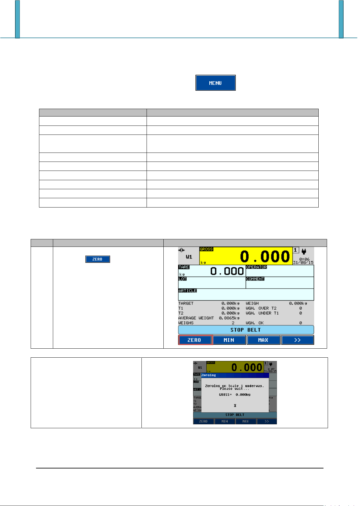
Step
Description
Screen
1
Press the key
A message appears on the display
during the zeroing.
5 MAIN FUNCTIONING DESCRIPTION
All the functions of the indicator are available from the button in the second screen.
The functions are divided into the following groups:
5.1 Zeroing
15
 Loading...