

Dini Argeo 3590EGT, 3590ET Connection Diagrams
3590ET / 3590EGT
Touch screen indicator
CONNECTION DIAGRAMS ENGLISH
www.diniargeo.com


Table of contents
Introduction 4
Electrical warnings 5
Electrical precautions 5
Cable classification 5
Recommended distance between cables 6
Maximum permitted length of cables 6
Earthing system 7
Example of weighbridge earthing 8
Example of silos earthing 9
Motherboard 10
I/O expansion board 12
Optional internal board for rapid connection of multiple scales 13
RJ45 RS232 connector board 13
RS232 / RS485 to Ethernet / WIFI conversion board 14
USB support data saving board 16
RADIO communication board 17
PROFIBUS communication board 17
BLUETOOTH communication board 18
RADIO REMOTE CONTROL board 18
Circuit breaker against electrostatic loads 18
Analog output 19
Traffic light 20
RS485 20
RS485 opto-isolated board 21
Display board 21
3590ET / 3590EGT
TECH_MAN_SCHEMES_3590_ENG_vX_17.06
3

Introduction
Dear Customer,
Thank you for purchasing a DINI ARGEO product.
This manual contains all instructions for proper installation of the weight indicator with touch screen series 3590.
We thank you for purchasing this scale and we kindly ask you to take note of certain aspects of this manual:
This booklet provides useful information for proper operation and maintenance of the scale referred to herein. It is important to pay the
utmost attention to all the sections that illustrate the simplest and safest way to operate the device.
This publication, or portions thereof, may not be duplicated without written permission from the Manufacturer.
All information herein is based on the data available at the time of publication. The Manufacturer reserves the right to make changes
to its products at any time without notice and without incurring any penalty. We therefore recommend that you always check for any
updates.
N.B.: The individual in charge of operating the scale must ensure that all safety regulations in force in the country of use are applied,
ensuring that the appliance is used in accordance with the purpose it is intended for and to avoid any danger for the user.
The manufacturer declines any liability arising from any weighing operation errors.
We recommend carefully following the instructions when programming the weight indicator, as to do otherwise could jeopardise proper
scale operation.
This manual was written with the utmost care but we always welcome feedback on any inaccuracies you may find.
The instrument is covered by warranty and MUST NOT BE TAMPERED WITH BY THE USER for any reason.
Any attempt to repair or modify the device could expose the user to the risk of electrical shock and will render all warranty conditions
null, thus releasing the Manufacturer from all liability.
All problems with the unit or system must be communicated to the manufacturer or the dealer from which it was purchased. In any
case, DISCONNECT POWER before any operations.
3590ET / 3590EGT
4
TECH_MAN_SCHEMES_3590_ENG_vX_17.06
Electrical warnings
Electrical precautions
• Mains power supply adjusted within ± 10% of the nominal voltage
• Electrical protections (fuses, etc.) are to be provided by the installer.
• Comply with the minimum recommended distances between different categories of cables.
• The load cell or signal amplifier extension cables, which are used for serial port and analog output connection, must comply with the maximum permitted lengths.
• The load cell or signal amplifier extension cables, which are used for serial port and analog output connection, must be
shielded and must also be inserted alone into the conduit or metal pipe.
• Cell or amplifier cable input into the electrical panel must be autonomous. If possible, they must be connected directly to
the indicator’s terminal board without passing through the conduit with other cables.
• Install an “RC” filter on coil contactors, solenoid valves and all devices that generate electrical interferences.
• If condensation can develop inside the scale’s transmitter, it is recommended to keep the equipment running.
• With regard to all shielded and non-shielded cables (cell cable, PC cable, power supply cable, etc.) that are connected to
the indicator, you must keep the cable as short as possible and make a minimum amount of the cables exit from the shield
in order to be connected to the terminal board;
• If the indicator is situated inside an electrical panel, you must also use a shielded cable for power supply and must keep
the cable as short as possible and far from the cables supplying coils, inverter, electromotive force, etc., and apply a
de-coupling transformer to supply the indicator only.
Cable classification
The various cables are classified according to the signals they transmit:
Category I
• Fieldbus , LAN network ( PROFIBUS, Ethernet, Devicenet...)
• Data shielded cables (RS232 ...)
• Shielded cables for analog digital signals < 25V (sensors, load cells.)
• Low-voltage power supply cables (<60V)
• Coaxial cables
Category II
• DC power supply cables with >60V and <400V
• AC power supply cables with >25V and <400
Category III
• Power supply cables with >400V
• Telephone cable
Category IV
• Any cables subject to lightning hazards
3590ET / 3590EGT
5
TECH_MAN_SCHEMES_3590_ENG_vX_17.06
Electrical warnings
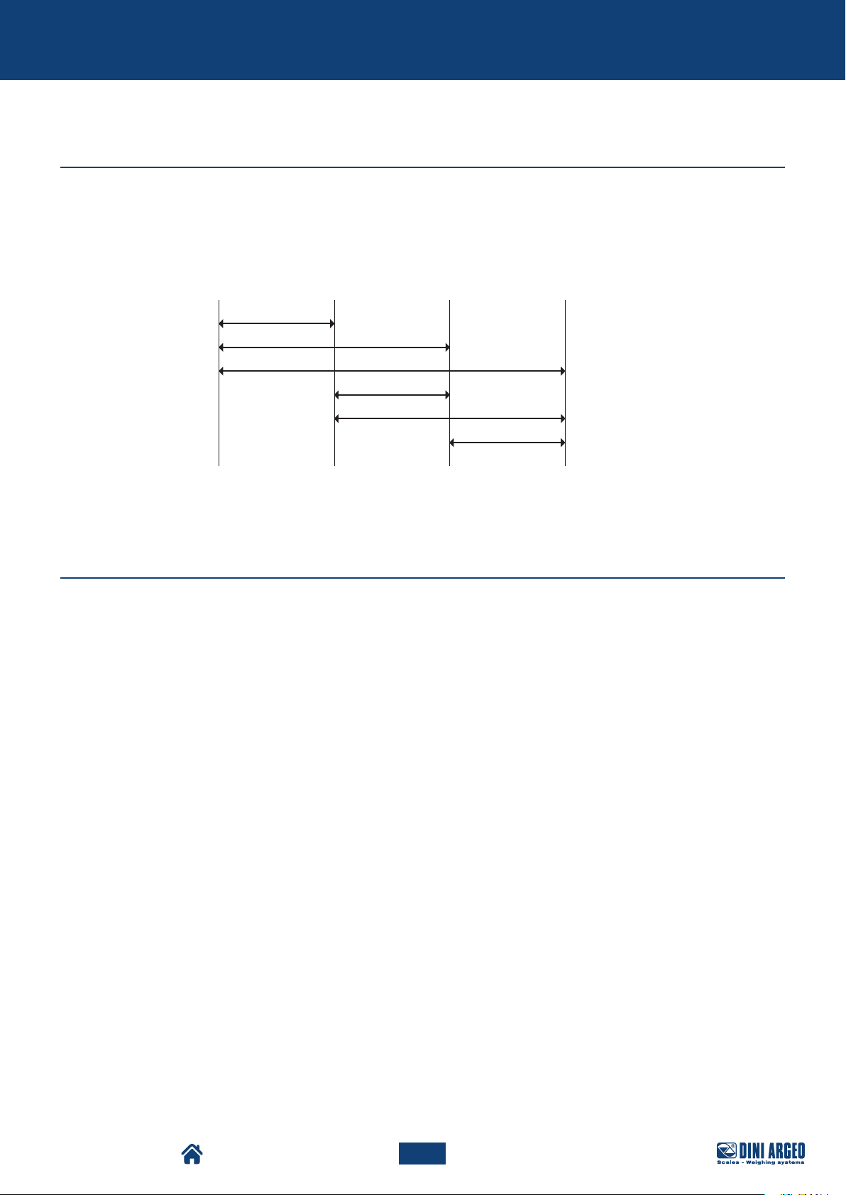
Recommended distance between cables
• When cables are laid parallel, they must be at the distances specified in the figure below
• These distances are intended in the air and are reduced if the housings are separated by metal boards connected to the
ground
• Cables from different categories can cross (90°)
Category I Category II Category III Category IV
≥ 100 mm
≥ 200 mm
≥ 500 mm
≥ 100 mm
≥ 500 mm
≥ 500 mm
Maximum permitted length of cables
LOAD CELL CONNECTION CABLE
The relative cable can reach the following maximum length from the line in order to connect the load cells:
• 50 metres with a 6 x 0.25 mm2 cable
• 100 metres with a 6 x 0.5 mm2 cable
RS232 CONNECTION CABLE
The relative cable can reach a maximum length of approximately 15 metres from the line for RS 232 connections, with a baud
rate of up to 19200.
RS485 CONNECTION CABLE
The relative cable can reach a maximum length of approximately 1200 metres from the line with a baud rate of up to 9600.
ANALOGUE OUTPUT CONNECTION CABLE
The maximum length for current analog output is:
• 100 metres with a 2 x 0.25 mm2 cable
• 150 metres with a 2 x 0.5 mm2 cable
• 300 metres with a 2 x 1 mm2 cable
The maximum length for voltage analog output is:
• 50 metres with a 2 x 0.25 mm2 cable
• 75 metres with a 2 x 0.5 mm2 cable
• 150 metres with a 2 x 1 mm2 cable
3590ET / 3590EGT
6
TECH_MAN_SCHEMES_3590_ENG_vX_17.06
Electrical warnings
Earthing system
For correct earthing and perfect system operation, you must connect the indicator, load cells, any junction boxes and weighing
structure to earth.
INDICATOR
Connect the container’s external earth terminal to earth with copper cables having a minimum dimension of 16 mm2.
LOAD CELLS AND JUNCTION BOX
Earthing must be carried out by connecting the earthing cables to the earth bar; the cables must have a minimum dimension of
16 mm2. Also, connect the earth bar to the earth pole with a minimum cable of 50 mm2.
• If the load cells are connected to the indicator via a junction box, you must connect the cable shield from the indicator and
the cell cable shields to the earth terminal of the junction box (refer to the junction box manual) and connect the latter to
earth by means of a copper cable having a minimum dimension of 16 mm2.
• If the load cells are connected directly to the indicator (without using a junction box), you must connect the cell cable
shields to the earthing point (or earth bar) inside the container.
• If the weighing system is for a large and/or outdoor structure, such as a weighbridge, and the junction box is connected to
the indicator with a cable longer than 10 m, or if there are interferences, connect the cable’s braiding from the indicator to
the earth terminal in the junction box and indicator and connect the two earth systems with an earth cable having a minimum dimension of 16 mm2.
WEIGHING STRUCTURE
Connect the weighing structure and any other structures that are not connected (for example silos that leave material on the
weighing structure) to earth with cables having a minimum dimension of 16 mm2.
You must also connect the upper part of each cell with the lower part of the cell with a copper braid having a minimum dimension of 16 mm2. The upper part must be short circuited with the surface of the weighing structure and the lower part must be
connected to earth with a copper braid having a minimum dimension of 16 mm2.
SERIAL CABLES AND INSTRUMENTS CONNECTED
Connect the serial cable shield to the earthing point (or earth bar) inside the container (on the end part of the cable towards
indicator) and to the earth terminal of the connected instrument (on the end part of the cable towards the instrument connected),
and connect the earth terminal of the connected instrument to earth with copper cables having a minimum dimension of 16 mm2.
To avoid undesired effects, the earthing references of the connection cable and power supply of the instrument connection and
the indicator must have the same power.
i
NOTES:
• ll earth cables must have a suitable length in order to obtain an overall resistance of the earthing system
below 1Ω.
• With regard to large and/or outdoor weighing system structures, such as a weighbridge:
- connection to earth must be carried out by connecting the earth cables to an earth bar, and the earth
bar to an earth pole with a minimum cable of 50 mm2.
- The cables must be larger (e.g. 50 mm2 instead of 16 mm2 and 100 mm2 instead of 50 mm2) since the
voltage involved is higher (e.g. lightning);
- the earth pole must be situated at a minimum distance of 10 m from the weighbridge structure;
• You must open SENSE inside the indicator in order to compensate for the shift due to an increase in temperature.
• You must check and, if necessary, remove the connection between electrical installation earth and neutral.
3590ET / 3590EGT
7
TECH_MAN_SCHEMES_3590_ENG_vX_17.06
Electrical warnings
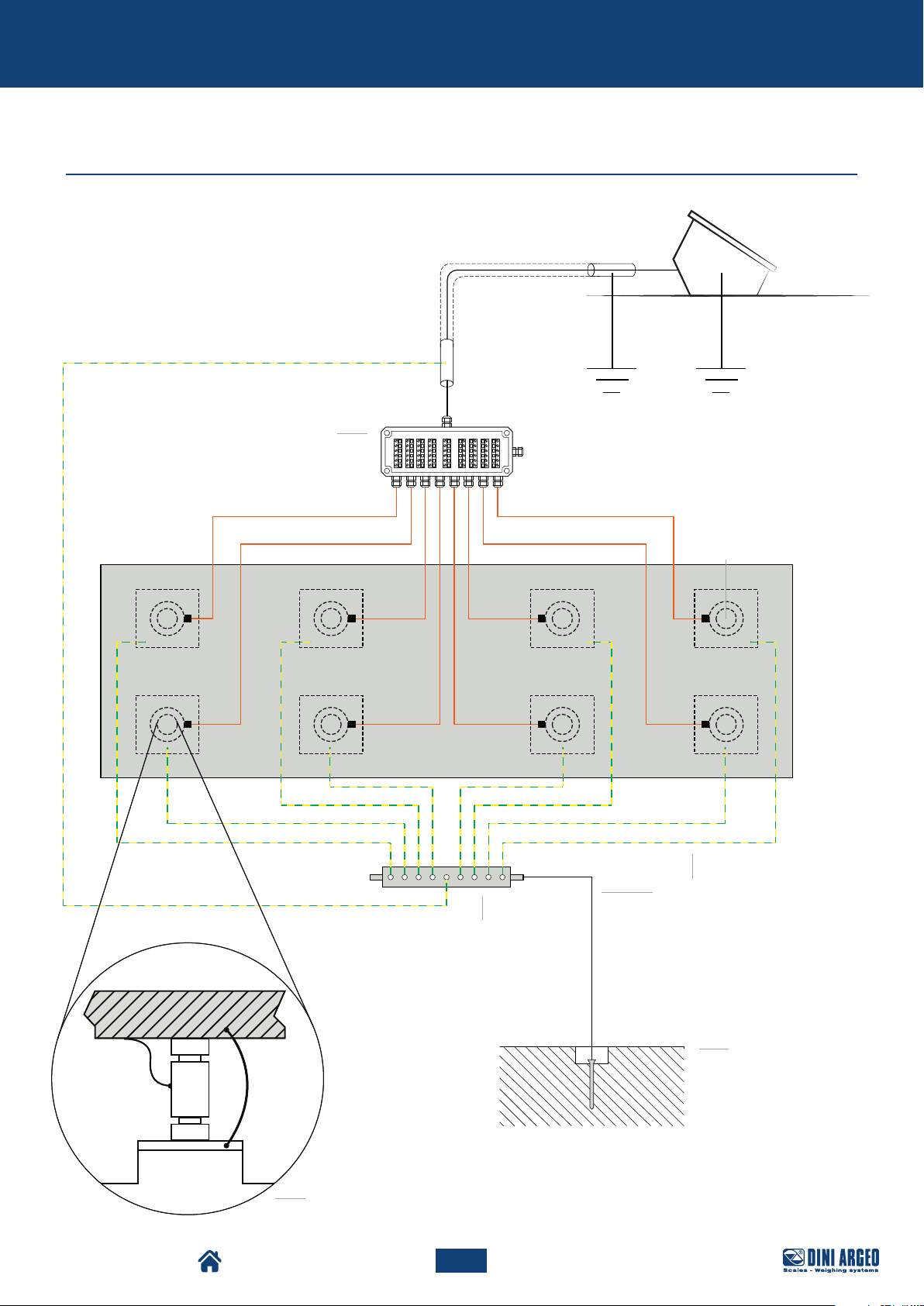
Weighbridge
Example of weighbridge earthing
Junction box situated on
the coast wall of the ditch
Weight indicator
Weighbridge
Copper perforated plate
placed on the coast wall
Load cell
Earth cables
Ø 8-sec 50 mm
Ø 11,3 - sec. 100 mm
2
2
3590ET / 3590EGT
Earth pole placed
under or next to
the weighbridge
Load cell
bypass U-bolt
8
TECH_MAN_SCHEMES_3590_ENG_vX_17.06
 Loading...